JP2010146053A - Count data recording device, and method and program for recording count data - Google Patents
Count data recording device, and method and program for recording count data Download PDFInfo
- Publication number
- JP2010146053A JP2010146053A JP2008319326A JP2008319326A JP2010146053A JP 2010146053 A JP2010146053 A JP 2010146053A JP 2008319326 A JP2008319326 A JP 2008319326A JP 2008319326 A JP2008319326 A JP 2008319326A JP 2010146053 A JP2010146053 A JP 2010146053A
- Authority
- JP
- Japan
- Prior art keywords
- count data
- count
- difference value
- data
- sorted
- Prior art date
- Legal status (The legal status is an assumption and is not a legal conclusion. Google has not performed a legal analysis and makes no representation as to the accuracy of the status listed.)
- Granted
Links
Images


Classifications
-
- G—PHYSICS
- G06—COMPUTING OR CALCULATING; COUNTING
- G06F—ELECTRIC DIGITAL DATA PROCESSING
- G06F11/00—Error detection; Error correction; Monitoring
- G06F11/07—Responding to the occurrence of a fault, e.g. fault tolerance
- G06F11/14—Error detection or correction of the data by redundancy in operation
- G06F11/1402—Saving, restoring, recovering or retrying
- G06F11/1405—Saving, restoring, recovering or retrying at machine instruction level
- G06F11/141—Saving, restoring, recovering or retrying at machine instruction level for bus or memory accesses
-
- G—PHYSICS
- G06—COMPUTING OR CALCULATING; COUNTING
- G06F—ELECTRIC DIGITAL DATA PROCESSING
- G06F11/00—Error detection; Error correction; Monitoring
- G06F11/07—Responding to the occurrence of a fault, e.g. fault tolerance
- G06F11/16—Error detection or correction of the data by redundancy in hardware
- G06F11/18—Error detection or correction of the data by redundancy in hardware using passive fault-masking of the redundant circuits
- G06F11/186—Passive fault masking when reading multiple copies of the same data
Landscapes
- Engineering & Computer Science (AREA)
- Theoretical Computer Science (AREA)
- Quality & Reliability (AREA)
- Physics & Mathematics (AREA)
- General Engineering & Computer Science (AREA)
- General Physics & Mathematics (AREA)
- Techniques For Improving Reliability Of Storages (AREA)
- Read Only Memory (AREA)
- Control Or Security For Electrophotography (AREA)
- Debugging And Monitoring (AREA)
Abstract
Description
本発明は、メモリ等で構成される記憶領域へカウントデータを記録する装置、および、カウントデータ記録方法に関し、特に、該記憶領域に記録されたカウントデータにおいて生じた破損を検出し、当該検出にかかる破損したカウントデータを正常な状態へ修復するカウントデータ記録装置、および、記録方法に関する。 The present invention relates to an apparatus and a count data recording method for recording count data in a storage area composed of a memory or the like, and more particularly, to detect damage that has occurred in count data recorded in the storage area and to detect the damage. The present invention relates to a count data recording apparatus and a recording method for restoring such damaged count data to a normal state.
従来、データの記録および保持には、メモリが利用される。特に、長期にわたって、データをメモリ内に保持する用途には、不揮発性メモリが用いられる。ここで、不揮発性メモリとは、電源を供給しなくても記憶を保持するメモリの総称である。 Conventionally, a memory is used for recording and holding data. In particular, a nonvolatile memory is used for a purpose of holding data in the memory for a long period of time. Here, the non-volatile memory is a general term for memories that retain memory even when power is not supplied.
しかしながら、不揮発性メモリ(例えば、EEPROM(Electrically Erasable and Programmable Read Only Memory))は、一般に、データの書き込みに関する繰り返し耐性が小さい。例えば、不揮発性メモリの書き込み繰り返し耐性は、その種類によって様々だが、例えば、100万回程度である。 However, a non-volatile memory (for example, EEPROM (Electrically Erasable and Programmable Read Only Memory)) generally has low repetition resistance regarding data writing. For example, the repeated write endurance of the non-volatile memory varies depending on the type, but is, for example, about 1 million times.
特定のデータのみを記録する用途に不揮発性メモリが用いられることもある。このような特定のデータの例としては、カウントデータがある。カウントデータとは、特定の値から所定値ずつインクリメントされて記録されることによって、何らかの回数をカウントするために用いられるデータである。(上記所定値が負の数であれば、カウントデータは、上記特定の値からデクリメントされつつ、順次、記録されるデータである。)カウントデータは、例えば、特定のデバイス(例えば、画像処理装置の感光体ユニット)が動作した回数を記録する用途に用いられる。 A nonvolatile memory may be used for recording only specific data. An example of such specific data is count data. The count data is data used to count a certain number of times by being recorded by being incremented by a predetermined value from a specific value. (If the predetermined value is a negative number, the count data is data that is sequentially recorded while being decremented from the specific value.) The count data is, for example, a specific device (for example, an image processing apparatus). The photoconductor unit) is used for recording the number of operations.
このようなカウントデータを、書き込み繰り返し耐性が比較的小さいメモリに記録する場合には、以下に記すようにしてカウントデータをメモリへ記録し、また、データが破壊されたときにはその修復を行う。 When such count data is recorded in a memory having a relatively low write repetition resistance, the count data is recorded in the memory as described below, and is repaired when the data is destroyed.
例えば、メモリの1つのアドレスに対する書き込み繰り返し耐性が100万回であるメモリを用いて、300万回のカウントデータの書き込みを行う場合、3つのアドレスを用いて、3つのアドレスに対し、順次的に、カウントデータの書き込みを行う。カウントデータは、所定値ずつ増加(あるいは減少)するため、上記3つのアドレスには、所定値ずつ増加(あるいは減少)する3つの値が、記録される。 For example, when writing 3 million times of count data using a memory having a write repetition resistance of 1 million times with respect to one address of the memory, using three addresses, sequentially with respect to the three addresses. Write count data. Since the count data increases (or decreases) by a predetermined value, three values that increase (or decrease) by a predetermined value are recorded at the three addresses.
カウントデータには、所定値ずつ増加(あるいは減少)するという性質が備わっているため、記録されたカウントデータが破壊された場合であっても、破壊されていないカウントデータの値を用いて、当該値に所定値あるいは所定値の2倍の値を加算(あるいは減算)して得られる値を、破壊されたアドレスに書き込むことで、破壊されたカウントデータを修復することができる。 Since the count data has the property of increasing (or decreasing) by a predetermined value, even if the recorded count data is destroyed, the count data value that is not destroyed is used. By writing a value obtained by adding (or subtracting) a predetermined value or a value twice the predetermined value to the value to the destroyed address, the destroyed count data can be restored.
このように、メモリの1つのアドレスに対する書き込み繰り返し耐性が100万回であるメモリを用いる場合、3つのアドレスを用いることで300万回のカウントデータの書き込み、および、その修復が可能である。 As described above, when using a memory having a write repetition resistance of 1 million times with respect to one address of the memory, the count data can be written and repaired 3 million times by using three addresses.
また、メモリの1つのアドレスに対する書き込み繰り返し耐性が100万回であるメモリを用いて、350万回のカウントデータの書き込みを行おうとする場合、次のようにして、350万回のカウントデータの記録を実現している例も存在する。 In addition, when writing a count data of 3.5 million times using a memory having a write repetition resistance of 1 million times for one address of the memory, recording of the count data of 3.5 million times is performed as follows. There is also an example that realizes.
先ず、所定の回数(例えば、97万回)までは、先の例と同様に、3つのアドレスに対し、順次的に、カウントデータの書き込みを行う。ここからは、先の例とは異なり、上記3つのアドレスとは別の3つのアドレスに対し、順次的に、カウントデータの書き込みが開始される。 First, up to a predetermined number of times (for example, 970,000 times), the count data is sequentially written to the three addresses as in the previous example. From here, unlike the previous example, the writing of count data is sequentially started to three addresses different from the above three addresses.
このような方法論によれば、350万回のカウントデータの書き込みを行うためには、カウントデータが書き込まれる6つのアドレスと、上記3つのアドレスそれぞれに対する書き込み回数を保持するための3つのアドレスと、上記3つのアドレス群および上記別の3つのアドレス群のいずれのアドレス群をカウントデータとして使用するかを示すデータが保持されるための1つのアドレスと、の総計10個のアドレスが必要になる。 According to such a methodology, in order to write count data for 3.5 million times, six addresses to which count data is written, three addresses for holding the number of times of writing for each of the three addresses, A total of ten addresses are required, one address for holding data indicating which of the three address groups and the other three address groups is used as count data.
理論上、350万回の書き込みがなされるカウントデータの記録は、100万回のデータ書き込みが可能なアドレスを4つ使えば足りる。にも拘わらず、上記の従来例においては、10個のアドレスを用いて、カウントデータの記録(および破損されたカウントデータの修復)を行う。このことは、メモリの利用効率の観点から好ましいこととは言えない。 Theoretically, the count data to be written 3.5 million times can be recorded by using four addresses that can be written 1 million times. Nevertheless, in the above conventional example, the count data is recorded (and the damaged count data is restored) using 10 addresses. This is not preferable from the viewpoint of memory utilization efficiency.
また、記録されたデータの誤りを検出して誤りを修復するための従来技術例として、以下の特許文献が存在する。 Further, the following patent documents exist as examples of conventional techniques for detecting errors in recorded data and correcting the errors.
特許文献1は、カウントデータを記録する装置であるカウンタを開示する。
特許文献1に記載のカウンタは、制御手段と、連続した複数の値からなる初期値が設定された複数のサブカウンタとを備える。
カウントアップ時においては、当該カウンタの制御手段は、複数のカウンタの持つ値のうちで最大の値と2番目に大きな値とが連続しているか否かを判断し、連続していないと判断した場合には、最小の値を持つサブカウンタの値を、2番目に大きな値に2を加算した値に書き換えて当該書き換えられた値をカウント値とし、また、連続していると判断した場合には、最小の値を持つサブカウンタの値を、最大の値に1を加算した値に書き換えて当該書き換えられた値をカウント値とする。
このような構成によって、特許文献1に記載のカウンタは、複数のサブカウンタが持つ値相互間の連続性に着目して各サブカウンタが持つ値が誤った値であるか正しい値であるかを判定し、正しい値であると判定された値を用いてカウント値の誤りを補正する。
The counter described in
At the time of counting up, the control unit of the counter determines whether or not the maximum value and the second largest value among the values of the plurality of counters are continuous, and determines that they are not continuous. In this case, when the value of the sub-counter having the smallest value is rewritten to the value obtained by adding 2 to the second largest value, the rewritten value is used as the count value, and when it is determined that the value is continuous Rewrites the value of the sub-counter having the minimum value to a value obtained by adding 1 to the maximum value, and uses the rewritten value as the count value.
With such a configuration, the counter described in
特許文献2は、画像形成装置に装着された交換ユニットの使用程度を表す情報を記憶する画像形成装置用寿命管理装置を開示する。
特許文献2に記載の装置は、交換ユニットの使用程度を表す情報を記憶する不揮発性メモリと、交換ユニットの使用程度を表す情報を不揮発性メモリに書き込む書込み手段と、不揮発性メモリに書き込まれた情報の誤りを検出して修復する修復処理手段と、を備える。また、当該不揮発性メモリには、3つ以上の、交換ユニットの使用程度を表す情報を記憶する領域が設けられている。
交換ユニットの使用程度を表す情報を書き込む際、当該装置の書込み手段は、同一内容の交換ユニットの使用程度を表す情報を、上記した3つ以上の領域のそれぞれに書き込む処理を行う。そして、該装置の修復処理手段は、上記した3つ以上の領域のそれぞれに書き込まれた情報が同一であるか否かを判断し、同一でないと判断した場合には、当該3つ以上の領域のそれぞれに書き込まれた情報が同一となるように修復処理を行う。
このような構成によって、特許文献2に記載の画像形成装置用寿命管理装置は、複数の記憶領域に書き込まれた情報が同一であるか否かに着目して誤った情報を検出し、該誤った情報を正しい情報に修復する。
Japanese Patent Application Laid-Open No. 2004-228688 discloses an image forming apparatus life management apparatus that stores information indicating the degree of use of an exchange unit attached to the image forming apparatus.
The apparatus described in
When writing information indicating the usage level of the replacement unit, the writing unit of the apparatus performs processing of writing information indicating the usage level of the replacement unit having the same contents in each of the three or more areas. Then, the repair processing means of the apparatus determines whether or not the information written in each of the above three or more areas is the same, and if it is determined that the information is not the same, the three or more areas The restoration processing is performed so that the information written in each of the two becomes the same.
With such a configuration, the lifetime management apparatus for an image forming apparatus described in
このように、カウントデータ等を記録し、適宜、誤ったカウントデータ等を正しいデータに修復するための技術は、数多く提示されている。
本発明は、メモリに対する書込繰り返し耐性とカウント可能な回数との相対的利用効率の観点において、メモリの利用効率が従来よりも向上され、かつ、破損を受けたカウントデータを修復できるカウントデータ記録装置を提供することを目的とする。 The present invention provides a count data recording in which the use efficiency of a memory is improved as compared with the related art and the damaged count data can be repaired in terms of the relative use efficiency of the write repetition resistance to the memory and the countable number of times. An object is to provide an apparatus.
本発明は、その一態様においては、所定値から所定幅で単調に変化するカウント値をカウントデータとして記憶領域に記録するカウントデータ記録装置であって、カウントデータを記憶する記憶領域をN個(Nは、4以上の整数)備える記憶部と、カウントデータを記憶部に書き込むデータ書込部と、カウントデータを記憶部から読み出すデータ読出部と、記憶部に記憶されたカウントデータの破損を検出し、該破損を修復するデータ修復部とを有し、データ書込部は、N個の記憶領域のなかから、カウントデータの記録に使用する記憶領域の順序を規定する所定の順序に従って、M個(Mは、3以上N未満の整数)の記憶領域を選択して小ループ範囲に定め、該小ループの範囲に含まれる記憶領域を所定の順序に沿って使用してカウントデータを記録し、該小ループ範囲の最後尾の記憶領域を使用してカウントデータを記録すると、該小ループ範囲を、所定の順序に沿って後方へずらして小ループ範囲を変更する、ようにして、カウントデータを記憶部に記録し、データ修復部は、N個の記憶領域に記憶されたカウントデータを、カウントデータの値が単調に変化するようにソートして被ソートカウントデータ列を導出し、被ソートカウントデータ列において互いに隣り合ったカウントデータ同士の差分値を求めてカウントデータ差分値列を導出し、当該被ソートカウントデータ列およびカウントデータ差分値列に基づいて、N個の記憶領域に記憶されたカウントデータの破損を検出して該破損を修復する、カウントデータ記録装置である。 In one aspect, the present invention is a count data recording apparatus that records a count value that changes monotonously from a predetermined value within a predetermined width as count data in a storage area, and includes N storage areas for storing count data ( N is an integer of 4 or more), a data writing unit that writes count data to the storage unit, a data reading unit that reads count data from the storage unit, and corruption of the count data stored in the storage unit And the data writing unit repairs the damage according to a predetermined order that defines the order of the storage areas used for recording the count data from among the N storage areas. (M is an integer of 3 or more and less than N) storage areas are selected and defined as a small loop range, and the storage areas included in the small loop range are used in a predetermined order to count data. When the count data is recorded using the storage area at the end of the small loop range, the small loop range is changed by shifting the small loop range backward in a predetermined order. The count data is recorded in the storage unit, and the data restoration unit sorts the count data stored in the N storage areas so that the value of the count data changes monotonously to derive a sorted count data string. Then, the difference value between the count data adjacent to each other in the sorted count data string is obtained to derive the count data difference value string, and N storages are performed based on the sorted count data string and the count data difference value string. This is a count data recording device that detects corruption of count data stored in an area and repairs the corruption.
本発明の一態様においては、データ修復部は、カウントデータ差分値列において1番目に位置する第1カウントデータ差分値からj番目(jは、1から(N−1)までの整数)に位置する第jカウントデータ差分値までのj個の差分値に基づいて、被ソートカウントデータ列における第j番目および第j+1番目に位置するカウントデータの少なくともいずれかの破損の有無を検出する、ことが好ましい。 In one aspect of the present invention, the data restoration unit is positioned jth (j is an integer from 1 to (N−1)) from the first count data difference value positioned first in the count data difference value sequence. Detecting whether or not the count data located at the jth and (j + 1) th in the sorted count data sequence is damaged based on j difference values up to the jth count data difference value to be detected. preferable.
本発明の一態様においては、データ修復部が被ソートカウントデータ列における第M番目に位置するカウントデータの破損を検出した場合には、データ修復部は、被ソートカウントデータ列における第1番目に位置するカウントデータの値を前記所定幅で除算し、当該除算にて得た商をMで除算したときに生じる剰余に基づいて、被ソートカウントデータ列における第M番目に位置するカウントデータを修復する、ことが好ましい。 In one aspect of the present invention, when the data repairing unit detects damage to the Mth-positioned count data in the sorted count data sequence, the data repairing unit is first in the sorted count data sequence. The Mth count data in the sorted count data string is repaired based on the remainder generated when the value of the count data positioned is divided by the predetermined width and the quotient obtained by the division is divided by M It is preferable to do.
本発明の一態様においては、データ修復部が被ソートカウントデータ列における第(M+k)番目(kは、1からN−Mの整数)に位置するカウントデータの破損を検出した場合には、データ修復部は、被ソートカウントデータ列における第(M+k−1)番目に位置するカウントデータの値に対してMと所定幅の積を加算して得た値を用いて、第(M+k)番目に位置するカウントデータの破損を修復する、ことが好ましい。 In one aspect of the present invention, when the data restoration unit detects damage to the count data located at the (M + k) th (k is an integer from 1 to NM) in the sorted count data string, The restoration unit uses the value obtained by adding the product of M and a predetermined width to the (M + k−1) th count data value in the sorted count data string, and uses the value obtained by adding the product of M and the predetermined width to the (M + k) th It is preferable to repair the corruption of the count data located.
本発明は、その別の一態様においては、カウントデータ記録装置が、所定値から所定幅で単調に変化するカウント値をカウントデータとして記憶領域に記録するカウントデータ記録方法であって、データ書込部が、カウントデータを記憶する記憶領域をN個(Nは、4以上の整数)備える記憶部の記憶領域のなかから、カウントデータの記録に使用する記憶領域の順序を規定する所定の順序に従って、M個(Mは、3以上N未満の整数)の記憶領域を選択して小ループ範囲に定めるステップと、データ書込部が、該小ループの範囲に含まれる記憶領域を所定の順序に沿って使用してカウントデータを記録するステップと、データ書込部が、該小ループ範囲の最後尾の記憶領域を使用してカウントデータを記録すると、該小ループ範囲を、所定の順序に沿って後方へずらして小ループ範囲を変更するステップと、データ修復部が、N個の記憶領域に記憶されたカウントデータを、カウントデータの値が単調に変化するようにソートして被ソートカウントデータ列を導出するステップと、データ修復部が、被ソートカウントデータ列において互いに隣り合ったカウントデータ同士の差分値を求めてカウントデータ差分値列を導出するステップと、データ修復部が、当該被ソートカウントデータ列およびカウントデータ差分値列に基づいて、N個の記憶領域に記憶されたカウントデータの破損を検出して該破損を修復するステップと、を有するカウントデータ記録方法である。 In another aspect, the present invention provides a count data recording method in which a count data recording device records a count value that monotonously changes from a predetermined value with a predetermined width as count data in a storage area. The storage unit has N storage areas for storing count data (N is an integer equal to or greater than 4). The storage unit has a predetermined order that defines the order of storage areas used for recording count data. , Selecting M storage areas (M is an integer greater than or equal to 3 and less than N) to determine a small loop range, and the data writing unit arranges the storage areas included in the small loop range in a predetermined order. And recording the count data using the storage area at the end of the small loop range, the data writing unit records the count data using the storage area at the end of the small loop range. The step of changing the small loop range by shifting backwards in the order, and the data restoration unit sorts the count data stored in the N storage areas so that the count data value changes monotonously. A step of deriving a sort count data string, a step of deriving a count data difference value string by obtaining a difference value between count data adjacent to each other in the sorted count data string, and a data repairing unit, A count data recording method comprising: detecting corruption of count data stored in N storage areas based on the sorted count data string and the count data difference value string and repairing the corruption.
本発明は、そのさらに別の一態様においては、所定値から所定幅で単調に変化するカウント値をカウントデータとして記憶領域に記録するカウントデータ記録装置のコンピュータが実行可能なカウントデータ記録プログラムであって、データ書込部に、カウントデータを記憶する記憶領域をN個(Nは、4以上の整数)備える記憶部の記憶領域のなかから、カウントデータの記録に使用する記憶領域の順序を規定する所定の順序に従って、M個(Mは、3以上N未満の整数)の記憶領域を選択して小ループ範囲に定めさせるステップと、データ書込部に、該小ループの範囲に含まれる記憶領域を所定の順序に沿って使用してカウントデータを記録させるステップと、データ書込部に、該小ループ範囲の最後尾の記憶領域を使用してカウントデータを記録すると、該小ループ範囲を、所定の順序に沿って後方へずらして小ループ範囲を変更させるステップと、データ修復部に、N個の記憶領域に記憶されたカウントデータを、カウントデータの値が単調に変化するようにソートして被ソートカウントデータ列を導出させるステップと、データ修復部に、被ソートカウントデータ列において互いに隣り合ったカウントデータ同士の差分値を求めてカウントデータ差分値列を導出させるステップと、データ修復部に、当該被ソートカウントデータ列およびカウントデータ差分値列に基づいて、N個の記憶領域に記憶されたカウントデータの破損を検出して該破損を修復させるステップと、を有するカウントデータ記録プログラムである。 According to another aspect of the present invention, there is provided a count data recording program that can be executed by a computer of a count data recording apparatus that records, as count data, a count value that changes monotonously from a predetermined value within a predetermined width in a storage area. The order of the storage areas used for recording the count data is defined from the storage areas of the storage section having N storage areas for storing the count data (N is an integer of 4 or more). Selecting M storage areas (M is an integer less than or equal to 3 and less than N) in accordance with a predetermined order to be determined as a small loop range, and storing data included in the small loop range in the data writing unit A step of recording the count data using the areas in a predetermined order, and the data writing unit using the storage area at the end of the small loop range Recording the data, the step of changing the small loop range by shifting the small loop range backward in a predetermined order, and the count data stored in the N storage areas in the data restoration unit A step of deriving the sorted count data string by sorting so that the value of the data monotonously changes, and obtaining a difference value between the count data adjacent to each other in the sorted count data string in the data restoration unit A step of deriving a value string, and a data repair unit detects damage of the count data stored in the N storage areas based on the count data string to be sorted and the count data difference value string, and repairs the damage A count data recording program.
本発明によるカウントデータ記録装置およびカウントデータ記録方法は、メモリに対する書込繰り返し耐性とカウント可能な回数との相対的利用効率の観点においてメモリの利用効率が従来よりも優れ、かつ、記録されたカウントデータが破損を受けた場合には、当該破損を修復し、正確なカウントデータに戻すことが可能である。 The count data recording apparatus and the count data recording method according to the present invention are superior in the use efficiency of the memory from the viewpoint of the relative use efficiency between the write repetition resistance to the memory and the number of counts, and the recorded count When the data is damaged, it is possible to repair the damage and return it to accurate count data.
本発明の実施の形態によるカウントデータ記録装置は、記憶装置の書き込み繰り返し耐性を超えてカウントデータを記録することが可能である。当該カウントデータ記録装置は、それぞれがカウントデータを記憶可能な記憶領域をN個(N:4以上の整数。)備える。カウントデータ記録装置は、カウント開始値C(Cは任意の数。)からインクリメント幅L(Lは0を除く数。)で単調に増加(Lが正数の場合。)(減少(Lが負数の場合。))するカウントデータを記録する。当該カウントデータ記録装置は、カウントデータを1回記録する度に、次に使用する記憶領域を所定の順序に従って変更する。
該カウントデータ記録装置においては、上記所定の順序における第N番目の記憶領域を使用してカウントデータを記録した場合、その次にカウントデータを記録するときは、原則として、上記所定の順序における第1番目の記憶領域を使用してカウントデータを記録するようにして、循環的にN個の記憶領域を使用する。本願においては、この、N個の記憶領域からなる、カウントデータの記録に使用する記憶領域の循環を「大ループ」と称する。
さらに、本発明の実施の形態によるカウントデータ記録装置は、上記「大ループ」の内部に含まれ、カウントデータの記録に使用する記憶領域を上記所定の順序に従って局所的に循環させるもう1つのループを備える。ここでは、この大ループ内における記憶領域のもう1つの循環を、「小ループ」と称する。「小ループ」は、M個(M:3以上N未満の整数。)の記憶領域からなり、1回のカウントデータの記録毎に順番に、次に使用する記憶領域を小ループ内で変更する。そして、小ループについての第M番目の記憶領域を使用してカウントデータを記録し、その次にカウントデータを記録するときは、小ループを構成するM個の記憶領域の範囲を、大ループ内における上記所定の順序に従って1つ後方へシフトさせ、新たな小ループの範囲を規定し、当該新たな小ループについての第1番目の記憶領域を使用してカウントデータを記録する。例えば、最初の小ループの範囲が、大ループについての第1番目から第M番目までのM個の記憶領域であれば、当該第M番目の記憶領域を使用してカウントデータを記録した後、小ループの範囲は、大ループについての第2番目から第(M+1)番目までのM個の記憶領域が新たな小ループの範囲となり、次のカウントデータの記録は、大ループについての第2番目の記憶領域に対して行われる。
小ループの範囲が、大ループについての第N番目の記憶領域を超えるような場合には、小ループの範囲は、大ループについての所定の順序に従って循環のルールに従って大ループの第1番目の記憶領域に戻って延びる。
The count data recording device according to the embodiment of the present invention can record count data exceeding the write repetition resistance of the storage device. The count data recording device includes N storage areas (N: an integer of 4 or more), each of which can store count data. The count data recording device monotonously increases (when L is a positive number) from the count start value C (C is an arbitrary number) (L is a number other than 0) (decrease (L is a negative number). In case of :)) Count data to be recorded. Each time the count data is recorded once, the count data recording device changes the storage area to be used next according to a predetermined order.
In the count data recording apparatus, when the count data is recorded using the Nth storage area in the predetermined order, when the count data is recorded next, in principle, the count data in the predetermined order is recorded. The count data is recorded using the first storage area, and N storage areas are used cyclically. In the present application, this circulation of storage areas used for recording count data, which is composed of N storage areas, is referred to as a “large loop”.
Further, the count data recording apparatus according to the embodiment of the present invention is another loop that is included in the “large loop” and locally circulates the storage area used for recording the count data in the predetermined order. Is provided. Here, another circulation of the storage area in the large loop is referred to as a “small loop”. The “small loop” is composed of M storage areas (M: an integer less than or equal to 3 and less than N), and the storage area to be used next is changed within the small loop in turn every time count data is recorded. . When the count data is recorded using the Mth storage area for the small loop and then the count data is recorded, the range of the M storage areas constituting the small loop is set within the large loop. Are shifted backward by one in accordance with the above-mentioned predetermined order, a new small loop range is defined, and count data is recorded using the first storage area for the new small loop. For example, if the range of the first small loop is M storage areas from the 1st to the Mth for the large loop, after the count data is recorded using the Mth storage area, In the small loop range, the second to (M + 1) th storage areas for the large loop are the new small loop range, and the next count data is recorded in the second loop for the large loop. To the storage area.
If the small loop range exceeds the Nth storage area for the large loop, the small loop range is the first storage of the large loop according to the rules of circulation according to a predetermined order for the large loop. Extend back to the area.
また、本発明にかかるカウントデータ記録装置は、カウントデータの破損を検出し、検出した破損を修復する。
本発明にかかるカウントデータ記録装置は、下記の原理に基づいて、カウントデータの破損を検出し、検出した破損を修復する。
上述したような方法でカウントデータを記録することにより、N個の記憶領域に記録されるカウントデータを、カウントデータの値に従って単調に変化するように(降順で(インクリメント幅Lが正数の場合。)または昇順で(インクリメント幅Lが負数の場合。))並べ替え(ソート)したときのカウントデータ列(被ソートカウントデータ列)は、有限個のパターン(カウントデータアドレス列パターン)のいずれかに一致する。また、被ソートカウントデータ列において互いに隣接するカウントデータ値の差分値がなす数列(カウントデータ差分値列)もまた、有限個のパターン(カウントデータ差分値列パターン)のいずれかに一致する。さらには、任意のカウントデータアドレス列パターンについて、当該カウントデータアドレス列パターンにおいて生じ得るカウントカウントデータ差分値列パターンとの対応関係もまた、各カウントデータアドレス列パターンについて高々有限個の予め定まった対応関係しか存在しない。しかるに、実際に記録されたカウントデータが正常であるか、破損を含んでいるか、は、当該カウントデータを、カウントデータの値でソートした被ソートカウントデータ列および被ソートカウントデータ列についてのカウントデータ差分値列が、カウントデータアドレス列パターンのいずれかと一致し、かつ、該カウントデータアドレス列パターンと対応しているカウントデータ差分値列パターンと一致するか、否か、に基づいて、判断することが可能である。
このような原理に基づいて、本発明にかかるカウントデータ記録装置は、カウントデータの破損を検出する。
また、本発明にかかるカウントデータ記録装置は、カウントデータの破損を検出した場合には、例えば、被ソートカウントデータ列において所定の順番に位置するカウントデータを正常なカウントデータであるとみなし、当該みなしにかかるカウントデータと、所定のカウントデータアドレス列パターンおよびカウントデータ差分値パターンとに基づいて、カウントデータの修復を行う。
In addition, the count data recording apparatus according to the present invention detects the corruption of the count data and repairs the detected corruption.
The count data recording apparatus according to the present invention detects breakage of count data and repairs the detected breakage based on the following principle.
By recording the count data by the method as described above, the count data recorded in the N storage areas changes monotonously according to the value of the count data (in descending order (when the increment width L is a positive number). .) Or in ascending order (when the increment width L is a negative number))) The count data string (sorted count data string) when rearranged (sorted) is one of a finite number of patterns (count data address string pattern) Matches. In addition, a number sequence (count data difference value sequence) formed by a difference value between count data values adjacent to each other in the sorted count data sequence also matches any of a finite number of patterns (count data difference value sequence pattern). Furthermore, for any count data address string pattern, the correspondence with the count count data difference value string pattern that can occur in the count data address string pattern is also at most a finite number of predetermined correspondences for each count data address string pattern. There is only a relationship. However, whether or not the actually recorded count data is normal or includes damage is determined depending on whether the count data is sorted by the count data value and the count data for the sorted count data string and the sorted count data string. Judgment is made based on whether or not the difference value string matches any of the count data address string patterns and the count data difference value string pattern corresponding to the count data address string pattern. Is possible.
Based on such a principle, the count data recording apparatus according to the present invention detects corruption of the count data.
In addition, when the count data recording device according to the present invention detects damage to the count data, for example, the count data positioned in a predetermined order in the sorted count data string is regarded as normal count data, and The count data is restored based on the count data regarding the disregard, the predetermined count data address string pattern, and the count data difference value pattern.
このような構成により、本発明による実施の形態にかかるカウントデータ記録装置は、記憶領域の繰り返し書き込み耐性を超えた回数のカウントデータの記録、ならびに、カウントデータの破損の検出、および、カウントデータの破損の修復を行うことができる。 With such a configuration, the count data recording apparatus according to the embodiment of the present invention records the count data exceeding the repeated write resistance of the storage area, detects the corruption of the count data, and Damage can be repaired.
<カウントデータ記録装置の構成>
図1は、本発明にかかる実施の形態によるカウントデータ記録装置を示す斜視図である。本実施の形態においては、カウントデータ記録装置は、デジタル複合機(MFP)1である。MFP1は、所謂、画像形成装置であり、画像形成のためにトナーカートリッジ3、および、感光体ユニット5を、内部に備える。
<Configuration of count data recording device>
FIG. 1 is a perspective view showing a count data recording apparatus according to an embodiment of the present invention. In the present embodiment, the count data recording apparatus is a digital multi-function peripheral (MFP) 1. The
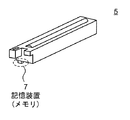
図2は、感光体ユニット5の斜視図である。感光体ユニット5は、その使用回数をカウントするカウントデータを記録するための記憶装置7を備える。記憶装置7は、データ書き込みについて、記憶領域に繰り返し書き込むことができる回数が規定されており、規定された繰り返し回数を超えて、データを書き込むことは、データ記録の安定性を損なう。
FIG. 2 is a perspective view of the
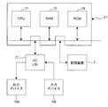
図3は、本発明にかかる実施の形態によるカウントデータ記録装置であるMFP1のハードウェア構成を示すブロック図である。MFP1は、データ処理や装置全体の動作の制御をする中央処理装置(CPU)11、プログラムやデータを保持するランダム・アクセス・メモリ(RAM)13、プログラムやデータを保持するリード・オンリ・メモリ(ROM)15を備え、これらはデータバスにより接続され、MFP1内においてコンピュータ21を構成する。コンピュータ21は、カウントデータ記録用プログラムを実行することにより、カウントデータ記録装置として機能する。
FIG. 3 is a block diagram showing a hardware configuration of
また、MFP1のコンピュータ21は、カウントデータを記録するための記憶装置7、各種デバイスとのデータ送受信をするためのI/OLSI17と接続される。I/OLSI17を介し、コンピュータ21は、出力デバイス19oおよび入力デバイス19iと接続される。
The
図4は、本発明の実施の形態によるカウントデータ記録装置にかかる機能を実現するためにMFP1が備える機能を表すブロック図である。コンピュータ21は、カウントデータ記録用プログラムを実行することにより、本図に示される機能を実現する。
FIG. 4 is a block diagram showing functions provided in
コンピュータ21は、各機能ブロックを制御する制御部23、記憶装置7に対しデータを所定のアドレス(記憶領域)に書き込むデータ書込部25、記憶装置7に記録されているカウントデータ等の破損を検出し、当該破損を修復するデータ修復部27、記憶装置7から所定のアドレス(記憶領域)に記録されたデータを読み出すデータ読出部29、および、カウントデータ記録用プログラムの実行に必要な設定データを保持する設定データ保持部31を実現する。
The
データ書込部25は、設定データ保持部31等に保持された設定データを参照してカウントデータを書き込むアドレス(記憶領域)を決定する書込アドレス決定部25a、および、決定されたアドレス(記憶領域)へ、カウントデータを書き込むカウントデータ書込部25bを備える。
The
データ修復部27は、データ読出部29が読み出した複数の所定のアドレス(記憶領域)に記録されたカウントデータを所定の規則(降順または昇順)で並べ替え、並べ替えた結果(被ソートカウントデータ列)を出力するカウントデータソート部27a、カウントデータソート部27aが並べ替えた結果(被ソートカウントデータ列)について互いに隣接するカウントデータ間の差分(カウントデータ差分値列)を算出するカウントデータ差分算出部27b、ならびに、被ソートカウントデータ列およびカウントデータ差分値列パターン、および、被ソートカウントデータ列において所定の順番に位置するカウントデータの値に基づいて、カウントデータの破損を検出し検出された破損を修復する修復処理実行部27cを備える。
The
修復処理実行部27cは、データ破損の検出のための処理、および、検出されたデータ破損の修復のための処理、を実行する。 The repair processing execution unit 27c executes processing for detecting data corruption and processing for repairing detected data corruption.
データ破損の検出処理は、上記被ソートカウントデータ列におけるアドレス(記憶領域)の並び方、上記被ソートカウントデータ列についてのカウントデータ差分値列の値の並び方、および、上記被ソートカウントデータ列における所定の順番に位置するカウントデータの値を、正常な(データ破損が含まれない)カウントデータを上記並べ替えした場合に起こり得るカウントデータの並び方(カウントデータアドレス列パターン)、および、各カウントデータアドレス列パターンについての互いに隣接するカウントデータの値の差分値の並び方(カウントデータ差分値列パターン)との組み合わせと比較することで、データ破損の生じているカウントデータを特定する。上記正常なカウントデータについて起こり得るカウントデータアドレス列パターンとカウントデータ差分値列パターンとの組み合わせは、データ破損の検出処理を実行する前に予め求めておき、装置が保持すればよい。上記カウントデータアドレス列パターンおよびカウントデータ差分値列パターンの数は、カウントデータの記録に用いるアドレスの数(大ループを構成するアドレスの総数N)および小ループを構成するアドレスの総数Mによって変化するが、いずれの場合においても高々有限個しかないため、保持可能である。 Data corruption detection processing is performed by arranging an address (storage area) in the sorted count data string, arranging a count data difference value string for the sorted count data string, and a predetermined value in the sorted count data string. The count data values positioned in the order of the count data that can be arranged when normal (not including data corruption) count data is rearranged as described above (count data address string pattern), and each count data address By comparing with the combination of the difference values of the count data values adjacent to each other for the column pattern (count data difference value column pattern), the count data in which data corruption has occurred is specified. A combination of a count data address string pattern and a count data difference value string pattern that can occur with respect to the normal count data may be obtained in advance before the data corruption detection process is executed and held by the apparatus. The number of the count data address string pattern and the count data difference value string pattern varies depending on the number of addresses used for recording count data (the total number N of addresses constituting the large loop) and the total number M of addresses constituting the small loop. However, in any case, since there is at most a finite number, it can be held.
データ破損の修復処理は、修復処理実行部27cが、データ破損の検出処理が検出した破損を含むカウントデータについて、上記カウントデータアドレス列パターンおよびカウントデータ差分値列パターンならびに被ソートカウントデータ列において所定の順番に位置するカウントデータの値に基づいて正常なカウントデータ値を求め、データ修復の指示を出力し、当該指示にもとづいて、データ書込部25のカウントデータ書込部25bが、正常なカウントデータ値を該当する記憶領域に書き込むことによって行われる。
In the data corruption repair process, the repair process execution unit 27c performs predetermined processing in the count data address string pattern, the count data difference value string pattern, and the sorted count data string for the count data including the damage detected by the data corruption detection process. A normal count data value is obtained based on the count data values positioned in the order of, and a data restoration instruction is output. Based on the instruction, the count data writing section 25b of the
設定データ保持部31は、記憶装置7の、カウントデータを記録するために用意されている複数のアドレス、当該アドレスに対してカウントデータの書き込みを実施する順序、当該アドレスの総数(大ループ構成アドレス総数N)、小ループ構成アドレス総数M、カウントデータのインクリメント幅L、カウント初期値C等を保持する。
The setting
<記憶装置7が保持するデータの構成>
図5は、記憶装置7において、複数の、アドレス指定された記憶領域に対し、カウントデータが書き込まれる際に使用されるアドレスの順序を説明する模式図である。
<Configuration of data held in
FIG. 5 is a schematic diagram for explaining the order of addresses used when count data is written to a plurality of addressed storage areas in the
アドレスとは、一般に、情報処理において、その処理の対象が存在する場所を規定する識別子である。本明細書においては、アドレスは、記憶装置7における記憶領域の特定のために用いる識別子を含む。
In general, an address is an identifier that defines a place where a processing target exists in information processing. In the present specification, the address includes an identifier used for specifying a storage area in the
ここでは、1つのアドレスによって指定される記憶領域は、カウントデータを保持するのに十分なビット幅を有する。しかしながら、本発明は、複数のアドレスによって規定される記憶領域を用いて1つのカウントデータを記録することを除外するものではない。 Here, the storage area specified by one address has a sufficient bit width to hold the count data. However, the present invention does not exclude recording one count data using a storage area defined by a plurality of addresses.
1つのアドレスによって特定される記憶位置の記憶容量が、1つのカウントデータを記憶するのに必要な記憶容量に満たない場合には、複数のアドレスによって特定される複数の記憶位置に、当該1つのカウントデータを分割して記憶すればよい。その場合、本発明にかかるカウントデータ記録装置は、1つカウントデータを書き込む複数の記憶領域の組み合わせの情報や、それぞれにカウントデータを書き込む順序の情報を保持すればよい。 If the storage capacity of the storage location specified by one address is less than the storage capacity necessary to store one count data, the one storage location specified by the plurality of addresses The count data may be divided and stored. In that case, the count data recording apparatus according to the present invention may hold information on a combination of a plurality of storage areas in which one piece of count data is written and information on the order in which the count data is written.
図5においては、図面左側に、N個(N:N>=4の正数。)の記憶領域が示される。該N個の記憶領域は、本発明における大ループを構成する記憶領域である。上述のように、N個の記憶領域には、カウントデータを書き込む順序が予め規定される。当該順序は、本図においては、第1の、第2の、・・・、第(N−1)の、第Nの、といった修飾語で表されている。 In FIG. 5, N storage areas (N: a positive number of N> = 4) are shown on the left side of the drawing. The N storage areas are storage areas constituting a large loop in the present invention. As described above, the order in which the count data is written is defined in advance in the N storage areas. The order is represented by modifiers such as the first, second,..., (N−1) th, and Nth in the figure.
また、上述のように、本発明においては、大ループ内部において、M個の記憶領域からなる小ループが構成される。該小ループを構成するアドレス(記憶領域)の総数は、M個であればよい。ここで、Mは、3以上であって、Nよりも小さい自然数であればよい。本図においては、M=3として、図を描いている。 In addition, as described above, in the present invention, a small loop composed of M storage areas is configured inside the large loop. The total number of addresses (storage areas) constituting the small loop may be M. Here, M may be a natural number that is 3 or more and smaller than N. In the figure, the figure is drawn with M = 3.
カウントデータの書き込みが行われる順序を説明する。先ず、カウントデータ記録装置は、最初に起動した場合にのみ、初期設定を実行する。初期設定において、第1ないし第Nの記憶領域に対し、初期値が書き込まれる。 The order in which the count data is written will be described. First, the count data recording apparatus executes initial setting only when it is first activated. In the initial setting, initial values are written in the first to Nth storage areas.
初期設定において、第1ないし第Nの記憶領域のそれぞれに書き込まれる初期値は、以下のようであることが望まれる。但、本発明にとってこの初期値の書き込みは必須でない。本発明においては、初期値の書き込みが行われない場合であっても、第1から第Nまでの各記憶領域に対し、それぞれ少なくとも1回のカウントデータの書き込みが行われた場合には、カウントデータの破損(異常)の検出および異常の修復をすることができる。
カウントデータの初期値は、
第i記憶領域(i:1<=i<M)に関し、
(初期値)=C−(M−i)・L、
第i記憶領域(i:M<=i<=N)に関し、
(初期値)=C−(N−i+1)・M・L、であることが望ましく、ここで、(C、L、M、N)は、(カウント開始値、カウントインクリメント幅、小ループ構成アドレス総数、大ループ構成アドレス総数)である。
In the initial setting, it is desirable that initial values written in the first to Nth storage areas are as follows. However, writing of the initial value is not essential for the present invention. In the present invention, even when the initial value is not written, if the count data is written at least once in each of the first to Nth storage areas, the count is performed. Data corruption (abnormality) can be detected and abnormalities can be repaired.
The initial value of the count data is
Regarding the i-th storage area (i: 1 <= i <M),
(Initial value) = C− (M−i) · L,
Regarding the i-th storage area (i: M <= i <= N),
It is desirable that (initial value) = C− (N−i + 1) · M · L, where (C, L, M, N) is (count start value, count increment width, small loop configuration address) Total number, large loop configuration address total number).
第1回目のカウントデータの書き込みにおいては、カウントデータ(カウント開始値C)は、第1の記憶領域に書き込まれる。(図中の「CD」は、カウントデータを表す。) In the first write of count data, the count data (count start value C) is written to the first storage area. ("CD" in the figure represents count data.)
第2回目のカウントデータの書き込みにおいては、カウントデータ(カウント開始値+カウントインクリメント幅=C+L)は、第2の記憶領域に書き込まれる。 In the second count data write, count data (count start value + count increment width = C + L) is written to the second storage area.
第3回目のカウントデータの書き込みにおいては、カウントデータ(C+2・L)は、第3の記憶領域に書き込まれる。 In the third count data write, the count data (C + 2 · L) is written to the third storage area.
さて、小ループ構成アドレス総数Mが、M=3である本図の例においては、第4回目のカウントデータ書込に際し、小ループの範囲が、アドレスの順序にそって後方に1つシフトされ、第2、第3、第4の記憶領域が、新たな小ループの範囲に設定される。
そして、第4回目のカウントデータの書き込みにおいては、カウントデータ(C+3・L)は、第2の記憶領域に書き込まれる。
Now, in the example of this figure in which the total number M of the small loop configuration addresses is M = 3, the small loop range is shifted backward by one according to the address order when the count data is written for the fourth time. The second, third, and fourth storage areas are set to a new small loop range.
In the fourth count data write, the count data (C + 3 · L) is written to the second storage area.
このようにして、第5、第6回目のカウントデータの書き込みは、それぞれ、第3の、第4の記憶領域に対してなされ、その後で、小ループの範囲が、先程と同様にして後方に1つシフトされる。そして、第7回目のカウントデータの書き込みは、第3の記憶領域になされる。 In this way, the fifth and sixth count data are written to the third and fourth storage areas, respectively, and then the small loop range is moved backward in the same manner as before. Shifted by one. The seventh count data is written to the third storage area.
上述したように、大ループの最後の記憶領域(第Nの記憶領域)の次は、第1の記憶領域へ戻り、繰り返し、第1の記憶領域から順番にカウントデータが書き込まれる。なお、小ループの範囲もまた、第Nの記憶領域を超える場合には、第1の記憶領域に戻って、小ループの範囲が設定される。 As described above, after the last storage area (Nth storage area) of the large loop, the process returns to the first storage area, and the count data is written sequentially from the first storage area. When the small loop range also exceeds the Nth storage area, the small loop range is set by returning to the first storage area.
このようにして、カウントデータ記録装置は、(書込アドレス決定部25aが)カウントデータを書き込むアドレスを決定し、(カウントデータ書込部25bが)カウントデータを当該アドレスにて指定される記憶領域に記録することで、カウントデータの記録を行う。
当業者にとっては、明白なことだが、上述のようにして、複数の記憶領域を循環的に使用してカウントデータの記録を行う場合、各記憶領域の繰り返し書き込み可能回数をR[回](R:自然数。)とすれば、大ループを構成するアドレス総数N(N:N>=4の整数。)を用いて、本発明にかかるカウントデータ記録装置は、R・N回のカウントデータの記録が可能である。よって、カウント値Cからカウント値Cmaxまで、インクリメント幅Lでカウントデータを記録する場合、少なくとも、(((Cmax−Cmin)/L)+1)/R以上の自然数だけアドレスがあればよい。記憶装置7の記憶領域の効率的使用の観点からは、(((Cmax−Cmin+1)/L)+1)/R以上の最小の自然数が最も有利である。
In this way, the count data recording device determines the address (in which the write
As will be apparent to those skilled in the art, when the count data is recorded by cyclically using a plurality of storage areas as described above, the number of times that each storage area can be repeatedly written is R [times] (R Is a natural number), the count data recording apparatus according to the present invention uses the total number N of addresses constituting the large loop (N: integer of N> = 4) to record the count data R · N times. Is possible. Therefore, when the count data is recorded with the increment width L from the count value C to the count value Cmax, it is sufficient that there are at least as many natural numbers as (((Cmax−Cmin) / L) +1) / R or more. From the viewpoint of efficient use of the storage area of the
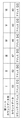
図6は、カウント開始値C=1、カウントインクリメント幅L=+1、小ループ構成アドレス総数M=3、大ループ構成アドレス総数N=6として、カウントデータの書き込みを26回実行した場合における、各記憶領域において保持されるカウントデータの値の推移を示す図である。本図においては、第iの記憶領域は、アドレス[i](i:1<=i<=6の整数。)と表記されている。また、斜線が付された部分は、各回のカウントデータ書き込みにおいてカウントデータが書き込まれる記憶領域を示している。 FIG. 6 shows each count when writing count data is executed 26 times with the count start value C = 1, the count increment width L = + 1, the small loop configuration address total number M = 3, and the large loop configuration address total number N = 6. It is a figure which shows transition of the value of the count data hold | maintained in a storage area. In this figure, the i-th storage area is described as an address [i] (i: 1 <= i <= 6). A hatched portion indicates a storage area in which count data is written in each count data write.
さて、このようにして各記憶領域(第1から第6の記憶領域)に対して書き込まれたカウントデータを、カウントデータの値に注目し、値の大きいものから順番に、つまり、降順で並べ替え(ソートし)てみる。なお、本発明においては、ソートは、カウントインクリメント幅Lが負数の場合には、値の小さいものから順番に、つまり、昇順でソートされる。 Now, the count data written to each storage area (first to sixth storage areas) in this way is focused on the value of the count data, and is arranged in descending order, that is, in descending order. Try changing (sorting). In the present invention, when the count increment width L is a negative number, sorting is performed in order from the smallest value, that is, in ascending order.
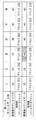
図7は、図6の各カウント回のカウント値(カウントデータの値)について降順でソートした場合の記憶領域の並びを示す図である。図中、I.〜VI.は、ソートされたカウントデータ列(被ソートカウントデータ列)の先頭からの各カウントデータの順番を示す。 FIG. 7 is a diagram showing the arrangement of storage areas when the count values (count data values) in FIG. 6 are sorted in descending order. In FIG. ~ VI. Indicates the order of count data from the beginning of the sorted count data string (sorted count data string).
このように、被ソートカウントデータ列の並び方は、パターン[01]からパターン[12]までの12通りがあり、それ以外の並び方は、カウントデータが正常な場合には、存在しない。本願では、この並び方のパターンをカウントデータアドレス列パターンと称している。
また、組み合わせの総数は、大ループ構成アドレス総数Nおよび小ループ構成アドレス総数Mを用いて、N・(M−1)と表すことができる。このように、任意の(M,N)の組み合わせについて、カウントデータアドレス列パターンは、有限である。
As described above, there are 12 ways to arrange the sorted count data string from pattern [01] to pattern [12], and no other way of arrangement exists when the count data is normal. In the present application, this arrangement pattern is referred to as a count data address string pattern.
Further, the total number of combinations can be expressed as N · (M−1) using the large loop configuration address total number N and the small loop configuration address total number M. Thus, the count data address string pattern is finite for any combination of (M, N).
図8は、カウントデータアドレス列パターンを整理した図である。このように、(M,N)=(3,6)の場合には、カウントデータアドレス列パターンは、パターン[01]からパターン[12]までの12通りである。 FIG. 8 is a diagram in which the count data address string pattern is organized. Thus, in the case of (M, N) = (3, 6), there are 12 count data address string patterns from pattern [01] to pattern [12].
次に、被ソートカウントデータ列およびカウントデータアドレス列パターンにおいて互いに隣接するカウントデータの値の差分値の並び方について説明する。 Next, how to arrange the difference values of the count data values adjacent to each other in the sorted count data string and the count data address string pattern will be described.
図9は、正常なカウントデータについて、任意の(M,N)で成立する差分値列の並びを示す図である。なお、簡単のために、本図においては、カウントインクリメント幅Lは、L=+1としている。任意のLについては、当業者であれば、本図より容易に導くことが可能であると思われるため、図示を省略する。 FIG. 9 is a diagram showing a sequence of difference value sequences that are established at an arbitrary (M, N) for normal count data. For the sake of simplicity, in this figure, the count increment width L is set to L = + 1. The arbitrary L is not shown because it is considered that those skilled in the art can easily derive it from this figure.
大ループを構成するアドレスの総数がNの場合、差分値の総数は、(N−1)となる。カウントデータを降順(または昇順)でソートした被ソートカウントデータ列において、先頭(第1番目)のカウントデータの値と、2番目のカウントデータの値との差分値を、第1カウントデータ差分値と称する。同様に、2番目のカウントデータの値と3番目のカウントデータの値との差分値を、第2カウントデータ差分値と称する。このようにして総数(N−1)個の差分値を区別し、その順に並べた数列を、カウントデータ差分値列と称する。
任意の(M,N)について、カウントデータ差分値列は、M通り存在する。
そして、各カウントデータ差分値列においては、第1カウントデータ差分値から第(M−2)カウントデータ差分値は、全て「1」(カウントインクリメント幅L)となり、第(M−1)カウントデータ差分値は、「1」から「M」までの整数のいずれか(j・L(j:1<=j<=M))となり、第Mカウントデータ差分値から第(N−1)カウントデータ差分値は、全て「M」(L・M)となる。このようにして、カウントデータ差分値列のパターン総数は、M通りとなる。
When the total number of addresses constituting the large loop is N, the total number of difference values is (N−1). In the sorted count data string in which the count data is sorted in descending order (or ascending order), the difference value between the value of the first (first) count data and the value of the second count data is set as the first count data difference value. Called. Similarly, a difference value between the value of the second count data and the value of the third count data is referred to as a second count data difference value. The total number (N−1) difference values are distinguished in this way, and the number sequence arranged in that order is referred to as a count data difference value sequence.
For any (M, N), there are M count data difference value sequences.
In each count data difference value sequence, the (M−2) th count data difference value from the first count data difference value is all “1” (count increment width L), and the (M−1) th count data. The difference value is one of integers from “1” to “M” (j · L (j: 1 <= j <= M)), and the (N−1) th count data from the Mth count data difference value. The difference values are all “M” (L · M). In this way, the total number of patterns in the count data difference value sequence is M.
図10は、(C,L,M,N)=(1,1,3,6)の場合におけるカウント回数0回目(初期値)から26回目までの各回の被ソートカウントデータ列についてのカウントデータ差分値列の詳細を示す図である。本例においては、M=3であるから、M−1=2である。上述のように、第1カウントデータ差分値は、常に、「1」であり、また、第3カウントデータ差分値から第5カウントデータ差分値は、常に、「M(M=3)」であり、第2カウントデータ差分値のみが、「1」から「M(M=3)」までの間の整数で順に変化することがわかる。 FIG. 10 shows the count data for each count data string to be sorted from the 0th count (initial value) to the 26th count in the case of (C, L, M, N) = (1, 1, 3, 6). It is a figure which shows the detail of a difference value row | line | column. In this example, since M = 3, M−1 = 2. As described above, the first count data difference value is always “1”, and the third count data difference value to the fifth count data difference value is always “M (M = 3)”. It can be seen that only the second count data difference value sequentially changes in an integer between “1” and “M (M = 3)”.
図11は、(C,L,M,N)=(1,1,3,6)の場合におけるカウントデータ差分値列を整理した図である。図より明らかなように、カウントデータ差分値列パターンは、パターン[1]からパターン[3]までの3通りである。 FIG. 11 is a diagram in which the count data difference value sequence is arranged in the case of (C, L, M, N) = (1, 1, 3, 6). As is apparent from the figure, there are three count data difference value sequence patterns from pattern [1] to pattern [3].
ここまで、(M,N)=(3,6)の場合においては、正常なカウントデータについての被ソートカウントデータ列について、カウントデータアドレス列パターンは、高々12通り、カウントデータ差分値列パターンは、高々3通りしか存在しないことを説明した。 Up to this point, in the case of (M, N) = (3, 6), the count data address string pattern for the count data string to be sorted for normal count data is 12 patterns at most, and the count data difference value string pattern is I explained that there are only 3 ways.
次に、図12を参照し、カウントデータアドレス列パターンと、カウントデータ差分値列パターンとの関係について説明する。図12は、各カウントデータアドレス列パターンについて、可能なカウントデータ差分値列パターンを示した図である。 Next, the relationship between the count data address string pattern and the count data difference value string pattern will be described with reference to FIG. FIG. 12 is a diagram showing possible count data difference value sequence patterns for each count data address sequence pattern.
このように、各カウントデータアドレス列パターンは、全てのカウントデータ差分値列パターンを取り得るものではない。寧ろ、各カウントデータアドレス列パターンは、限定されたカウントデータ差分値列パターンを取り得る。例えば、カウントデータアドレス列パターン[01]、[03]、[05]、[07]、[09]、[11]のいずれかに従う(正常な)被ソートカウントデータ列においては、カウントデータ差分値列パターン[1]および[3]のいずれかが成立する。また、カウントデータアドレス列パターン[02]、[04]、[06]、[08]、[10]、[12]のいずれかに従う(正常な)被ソートカウントデータ列においては、カウントデータ差分値列パターン[2]のみが成立する。本図は、(M,N)=(3,6)の場合について示す図であるが、任意の(M,N)の組み合わせについて、各カウントデータアドレス列パターンが取り得るカウントデータ差分値列パターンの総数は、有限であり、その特定も容易である。このことは、当業者であれば、容易に理解される事柄と思われる。 Thus, each count data address string pattern cannot take all count data difference value string patterns. Rather, each count data address string pattern can take a limited count data difference value string pattern. For example, in a (normal) sorted count data string according to any of the count data address string patterns [01], [03], [05], [07], [09], and [11], the count data difference value One of the column patterns [1] and [3] is established. Further, in the (normal) sorted count data string according to any of the count data address string patterns [02], [04], [06], [08], [10], and [12], the count data difference value Only the column pattern [2] is established. This figure shows the case of (M, N) = (3, 6), but the count data difference value sequence pattern that each count data address sequence pattern can take for any combination of (M, N). The total number is limited, and it is easy to specify. This seems to be easily understood by those skilled in the art.
本発明による実施の形態によるカウントデータ記録装置は、上記したように、カウントデータソート部27a(図4)が、被ソートカウントデータ列を作成し、カウントデータ差分算出部27b(図4)が、該被ソートカウントデータ列のカウントデータ差分値列を算出し、修復処理実行部27cは、被ソートカウントデータ列およびそのカウントデータ差分値列を、予め保持するカウントデータアドレス列パターンおよびカウントデータ差分値列パターンと比較することによって、カウントデータの破損(異常)を検出し、検出した異常なカウントデータを、被ソートカウントデータ列の所定の順番に位置するカウントデータの値、ならびに、カウントデータアドレス列パターンおよびカウントデータ差分値列パターンとに基づいて、修復する。
In the count data recording device according to the embodiment of the present invention, as described above, the count
以下、本発明による実施の形態によるカウントデータ記録装置におけるカウントデータの書き込み、ならびに、異常の検出および異常の修復にかかる処理について説明する。 Hereinafter, processing related to writing of count data and detection of abnormality and repair of abnormality in the count data recording apparatus according to the embodiment of the present invention will be described.
<カウントデータ書き込み処理>
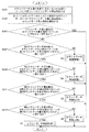
図13は、カウントデータ記録装置1(図1)が記憶装置7(図2)の記憶領域に対してカウントデータを書き込む処理を示すフローチャートである。
<Count data writing process>
FIG. 13 is a flowchart showing a process in which the count data recording device 1 (FIG. 1) writes count data to the storage area of the storage device 7 (FIG. 2).
ステップS101において、データ書込部25(図4)は、初期設定として記憶装置7の記憶領域に初期値を書き込む。この処理は、カウントデータ記録装置1が初めて起動した場合や、記憶装置7が換装された場合にのみ行えば足りる。
In step S101, the data writing unit 25 (FIG. 4) writes an initial value in the storage area of the
ステップS103において、制御部23(図4)は、データ書込部25に対し、カウントデータ書込指示を送る。
データ書込部25が、カウントデータ書込指示を受けた場合(ステップS103における「YES」)、処理は、ステップS105へ移行する。
データ書込部25が、カウントデータ書込指示を受けていない場合(ステップS103における「NO」)、処理は、ステップS103を繰り返す。
In step S103, the control unit 23 (FIG. 4) sends a count data write instruction to the
When
If
ステップS105において、データ書込部25は、その書込アドレス決定部25aが、カウントデータを書き込む記憶装置7内記憶領域を決定し、カウントデータ書込部25bが当該記憶領域へカウントデータを書き込むことで、カウントデータの書き込みを1回行う。このとき、書込アドレス決定部25aやカウントデータ書込部25bは、設定データ保持部31等を参照する。そうすることで、書き込むべき記憶領域や、書き込むべきカウントデータの値は、決定される。
In step S105, the
ステップS107からステップS121において、書込アドレス決定部25aは、次回のカウントデータ書き込みにおいて使用する記憶領域および次回のカウントデータ書き込みにおいて書き込むカウントデータの値を設定する処理を開始する。
In steps S107 to S121, the write
ステップS107において、書込アドレス決定部25aは、直前に実行したステップS105においてカウントデータを書き込んだ記憶領域のアドレスが、大ループにおける第N番目のアドレスであるか、否かについて判定する。
直前のステップS105においてカウントデータを書き込んだ記憶領域のアドレスが、大ループにおけるアドレス順序の最後尾のアドレス(アドレス[N])である場合(ステップS107における「YES」)、処理は、ステップS111へ移行する。
直前のステップS105においてカウントデータを書き込んだ記憶領域のアドレスが、大ループにおけるアドレス順序の最後尾のアドレスでない場合(ステップS107における「NO」)、処理は、ステップS109へ移行する。
In step S107, the write
When the address of the storage area in which the count data is written in the immediately preceding step S105 is the last address (address [N]) in the address sequence in the large loop (“YES” in step S107), the process proceeds to step S111. Transition.
When the address of the storage area in which the count data is written in the immediately preceding step S105 is not the last address in the address sequence in the large loop (“NO” in step S107), the process proceeds to step S109.
ステップS109において、書込アドレス決定部25aは、大ループにおけるアドレス順序において直前のステップS105においてカウントデータを書き込んだ記憶領域の次の順番で管理されている記憶領域を、次データ書込アドレスに設定する。
In step S109, the write
ステップS111において、書込アドレス決定部25aは、大ループにおけるアドレス順序において先頭(第1番目)で管理されている記憶領域を、次データ書込アドレスに設定する。
In step S111, the write
ステップS113において、書込アドレス決定部25aは、ステップS109またはステップS111で設定した次データ書込アドレスが現在の小ループの範囲を超えているか、否か、判定する。
書込アドレス決定部25aが、次データ書込アドレスは現在の小ループの範囲を超えていると判定した場合(ステップS113における「YES」)、処理は、ステップS115へ移行する。
書込アドレス決定部25aが、次データ書込アドレスは現在の小ループの範囲を超えていないと判定した場合(ステップS113における「NO」)、処理は、ステップS115、S117をスキップして、ステップS119へ移行する。
In step S113, the write
If write
If the write
ステップS115において、書込アドレス決定部25aは、大ループにおけるアドレス順序に沿って、小ループの範囲を1アドレス分だけ後方へシフトさせて、新たな小ループの範囲として管理する。
In step S115, the write
ステップS117において、書込アドレス決定部25aは、当該新たな小ループの範囲の先頭(第1番目)として管理されるアドレスを、次データ書込アドレスに設定する。
In step S117, the write
ステップS119において、書込アドレス決定部25aは、現在、次データ書込アドレスに設定されているアドレスを、データ書込アドレスに決定し、設定する。
In step S119, the write
ステップS121において、データ書込部25は、直前に実行したステップS105において書き込んだカウントデータの値に、カウントインクリメント幅Lを加算して取得した値を、カウント値に設定する。
なお、新たなデータ書込アドレスや、新たなカウント値は、書込アドレス決定部25aが保持してもよいし、あるいは、一旦、設定データ保持部31等に記録してもよい。
In step S121, the
The new data write address and the new count value may be held by the write
ステップS123において、制御部23は、カウントデータ書込処理を終了するか、否か、判定する。
制御部23が、カウントデータ書込処理を継続すると判定した場合(ステップS123における「YES」)、処理は、ステップS103へ戻る。
制御部23が、カウントデータ書込処理を終了すると判定した場合(ステップS123における「NO」)、全てのカウントデータ書込処理が終了する。
In step S123, the
When
When the
<カウントデータ破損検出処理および破損修復処理>
これより、本発明の実施の形態によるカウントデータ記録装置におけるカウントデータの異常(破損)の検出、および、破損の修復にかかる処理について説明する。
<Count data damage detection processing and damage repair processing>
Hereinafter, processing relating to detection of abnormality (damage) of count data and repair of damage in the count data recording apparatus according to the embodiment of the present invention will be described.
図14は、主としてデータ修復部27が実行する、カウントデータの異常の検出および検出された異常の修復にかかる処理を示すフローチャートである。
FIG. 14 is a flowchart showing processing related to detection of abnormality of count data and repair of detected abnormality mainly executed by the
ステップS201との関連において、データ読出部29は、記憶装置7の第1から第Nの記憶領域に記録されたカウントデータを読み出して、データ修復部27へ送る。
In relation to step
ステップS201において、データ修復部27のカウントデータソート部27aは、データ読出部29から受け取ったカウントデータを、各カウントデータの値の降順で、並べ替え(ソート)する。ここでは、ソートされたカウントデータの並びを、被ソートカウントデータ列と称する。被ソートカウントデータ列は、カウントデータソート部27aからカウントデータ差分算出部27bへ送られる。
In step S201, the count
ステップS203において、カウントデータ差分算出部27bは、被ソートカウントデータ列において互いに隣接するカウントデータの値について差分値を算出する。当該差分値は、複数個の数値からなる数列である。カウントデータ差分算出部27bは、差分値を被ソートカウントデータ列のカウントデータの並びと整合するように並べて数列を作成し、当該数列を修復処理実行部27cへ送る。ここでは、上記差分値からなる数列を、被ソートカウントデータ列についてのカウントデータ差分値列と称する。 In step S203, the count data difference calculating unit 27b calculates a difference value for the count data values adjacent to each other in the sorted count data string. The difference value is a numerical sequence composed of a plurality of numerical values. The count data difference calculation unit 27b arranges the difference values so as to match the count data of the sorted count data sequence, creates a number sequence, and sends the number sequence to the repair processing execution unit 27c. Here, the sequence of the difference values is referred to as a count data difference value sequence for the sorted count data sequence.
ステップS205において、修復処理実行部27cは、被ソートカウントデータ列についてのカウントデータ差分値列が、カウントデータ差分値列パターン(図9、図11等)のいずれかと一致するか、否か、を判定する。
修復処理実行部27cが、被ソートカウントデータ列についてのカウントデータ差分値列はカウントデータ差分値列パターンのいずれか1つと一致すると判定した場合(ステップS205における「YES」)、処理は、終了する。つまり、ステップS205において「YES」と判定される場合とは、修復処理実行部27cは、被ソートカウントデータ列には異常なカウントデータ(破損されたカウントデータ)が含まれないと判定した場合に相当する。
修復処理実行部27cが、被ソートカウントデータ列についてのカウントデータ差分値列はカウントデータ差分値列パターンのいずれとも一致しないと判定した場合(ステップS205における「NO」)、処理は、ステップS207へ移行する。つまり、ステップS205において「NO」と判定される場合とは、修復処理実行部27cは、被ソートカウントデータ列に異常なカウントデータ(破損されたカウントデータ)が含まれると判定した場合に相当する。以降の処理において、修復処理実行部27cは、破損されたカウントデータの修復処理を実行する。
In step S205, the repair processing execution unit 27c determines whether or not the count data difference value sequence for the sorted count data sequence matches any of the count data difference value sequence patterns (FIG. 9, FIG. 11, etc.). judge.
When the restoration process execution unit 27c determines that the count data difference value sequence for the sorted count data sequence matches any one of the count data difference value sequence patterns ("YES" in step S205), the process ends. . That is, the case where “YES” is determined in step S205 means that the repair processing execution unit 27c determines that abnormal count data (corrupted count data) is not included in the sorted count data string. Equivalent to.
When the restoration process execution unit 27c determines that the count data difference value sequence for the sorted count data sequence does not match any of the count data difference value sequence patterns ("NO" in step S205), the process proceeds to step S207. Transition. That is, the case where “NO” is determined in step S205 corresponds to the case where the repair processing execution unit 27c determines that abnormal count data (damaged count data) is included in the sorted count data string. . In the subsequent processing, the repair processing execution unit 27c executes repair processing for the damaged count data.
ステップS207において、修復処理実行部27cは、被ソートカウントデータ列についてのカウントデータ差分値列の第1番目の差分値が、カウントデータ差分値列パターンのいずれかの第1カウントデータ差分値と一致するか、否か、を判定する。
修復処理実行部27cが、被ソートカウントデータ列についてのカウントデータ差分値列の第1番目の差分値はカウントデータ差分値列パターンのいずれかの第1カウントデータ差分値と一致すると判定した場合(ステップS207における「YES」)、処理は、ステップS209へ移行する。
修復処理実行部27cが、被ソートカウントデータ列についてのカウントデータ差分値列の第1番目の差分値はカウントデータ差分値列パターンの第1カウントデータ差分値のいずれとも一致しないと判定した場合(ステップS207における「NO」)、処理は、ステップS3へ移行する。
In step S207, the repair processing execution unit 27c matches the first difference value of the count data difference value sequence for the sorted count data sequence with the first count data difference value of any of the count data difference value sequence patterns. It is determined whether or not.
When the restoration process execution unit 27c determines that the first difference value of the count data difference value sequence for the sorted count data sequence matches the first count data difference value of any of the count data difference value sequence patterns ( The process proceeds to step S209 when “YES” in step S207).
When the restoration process execution unit 27c determines that the first difference value of the count data difference value sequence for the sorted count data sequence does not match any of the first count data difference values of the count data difference value sequence pattern ( The process proceeds to step S3 (“NO” in step S207).
(カウントデータ修復処理1)
図15は、カウントデータ修復処理1(図14におけるS3)の詳細を示すフローチャートである。これより、図15を参照してカウントデータ修復処理1について説明する。
カウントデータ修復処理1は、第1カウントデータ差分値が正常でない場合に実行される修復処理である。第1カウントデータ差分値は、被ソートカウントデータ列における先頭(1番目)と2番目に位置するカウントデータの値の差分値である。よって、第1カウントデータ差分値が正常な値を示さないことは、被ソートカウントデータ列における1番目のカウントデータの値、および、2番目のカウントデータの値の少なくともいずれか一方が破損していることを意味する。
これより説明するカウントデータ修復処理1においては、被ソートカウントデータ列の先頭に位置するカウントデータの値を正常な値であると認定し、被ソートカウントデータ列の2番目以降に位置するカウントデータの値を修復する。
(Count data restoration process 1)
FIG. 15 is a flowchart showing details of the count data restoration process 1 (S3 in FIG. 14). The count
The count
In the count
ステップS301において、修復処理実行部27cは、被ソートカウントデータ列の1番目に位置するカウントデータのアドレスを取得する。 In step S301, the repair process execution unit 27c acquires the address of the count data positioned first in the sorted count data string.
ステップS303において、修復処理実行部27cは、ステップS301において取得したアドレスが先頭に位置するカウントデータアドレス列パターン(図8参照。)を抽出し、抽出されたパターンを修復用の候補パターンとする。 In step S303, the repair processing execution unit 27c extracts a count data address string pattern (see FIG. 8) in which the address acquired in step S301 is located at the head, and uses the extracted pattern as a repair candidate pattern.
ステップS305において、修復処理実行部27cは、ステップS303において抽出した修復用の候補パターンに対応するカウントデータ差分値列パターン(図11参照。)を抽出し、抽出したカウントデータ差分値列パターンを、ステップS303において抽出した候補パターンと対応付けて(図12参照。)、保持する。 In step S305, the repair processing execution unit 27c extracts the count data difference value sequence pattern (see FIG. 11) corresponding to the repair candidate pattern extracted in step S303, and the extracted count data difference value sequence pattern is The candidate patterns extracted in step S303 are associated with each other (see FIG. 12) and stored.
ステップS307において、修復処理実行部27cは、ステップS303およびステップS305において抽出した候補パターンおよび該候補パターンに対応するカウントデータ差分値列パターンのなかから、カウントデータ差分値列パターンがカウントデータ差分値列パターン[1](図11)であるカウントデータアドレス列パターンを特定し、当該カウントデータアドレス列パターンおよびそれと対応付けられたカウントデータ差分値列パターンを、修復に用いるカウントデータアドレス列パターンおよびカウントデータ差分値列パターンに決定する。
なお、本ステップの本質的意義は、修復されたカウントデータについての被ソートカウントデータ列のカウントデータ差分値列を、1(より一般にはカウントインクリメント幅L)と、M(より一般にはL・M)のみになるように、被ソートカウントデータ列の2番目からN番目までに位置するカウントデータの値を修復することにある。また、カウントデータ差分値列が、1(より一般にはカウントインクリメント幅L)と、M(より一般にはL・M)のみで構成されることは、第(M−1)カウントデータ差分値が1(より一般にはL)であることに対応する。(第(M−1)カウントデータ差分値以外のカウントデータ差分値は、カウントデータが正常であれば、常に、1とM(より一般には、LとL・M)のみからなる。)
In step S307, the repair processing execution unit 27c calculates the count data difference value sequence pattern from the candidate patterns extracted in steps S303 and S305 and the count data difference value sequence pattern corresponding to the candidate pattern. A count data address string pattern that is pattern [1] (FIG. 11) is specified, and the count data address string pattern and count data difference value string pattern associated therewith are used for restoration The difference value sequence pattern is determined.
The essential significance of this step is that the count data difference value sequence of the sorted count data sequence for the restored count data is 1 (more generally count increment width L) and M (more generally L · M ), The count data values positioned from the second to the Nth in the sorted count data string are restored. Further, the count data difference value sequence is composed of only 1 (more generally, count increment width L) and M (more generally, L · M). The (M−1) th count data difference value is 1 (More generally L). (The count data difference value other than the (M-1) th count data difference value is always composed of only 1 and M (more generally, L and L · M) if the count data is normal.)
ステップS309において、修復処理実行部27cは、ステップS307において決定した修復用カウントデータアドレス列パターンおよびそれと対応付けられたカウントデータ差分値列パターン(カウントデータ差分値列パターン[1])ならびに被ソートカウントデータ列の1番目のカウントデータの値に基づいて、被ソートカウントデータ列の2番目以降に位置するカウントデータの値を修復する。 In step S309, the repair processing execution unit 27c determines the repair count data address sequence pattern determined in step S307, the count data difference value sequence pattern (count data difference value sequence pattern [1]) associated therewith, and the sorted count. Based on the value of the first count data in the data string, the value of the count data located after the second count data string to be sorted is restored.
ステップS309の処理が完了すると、修復処理は終了する(図14)。 When the process of step S309 is completed, the repair process ends (FIG. 14).
なお、カウントデータ修復処理1は、任意の(M,N)の組み合わせにおいては、被ソートカウントデータ列の第1カウントデータ差分値から第kカウントデータ差分値(k:1<=k<=M−3の整数。)までが1(より一般には、カウントインクリメント幅L)であって、第(k+1)カウントデータ差分値が1ではない(より一般には、Lでない)ようなカウントデータ異常が検出された場合において、カウントデータの破損を修復するときに使用可能である。
Note that the count
(カウントデータ修復処理1変形例1)
図16は、カウントデータ修復処理の変形例(第1の変形例)を示すフローチャートである。これより、図16を参照してカウントデータ修復処理1変形例1について説明する。
カウントデータ修復処理1変形例1は、第1カウントデータ差分値が正常でない場合には、カウントデータが破損したことを通知する処理を実行する。カウントデータ修復処理1変形例1においては、カウントデータの異常を修復処理は行われない。
(Count
FIG. 16 is a flowchart showing a modified example (first modified example) of the count data restoration process. The count
Count
ステップS311において、修復処理実行部27cは、カウントデータが破損していることを示す通知(カウントデータ異常)を出力する。当該出力は、例えば、制御部23(図4)へ送られ、制御部23は、当該出力に基づいて所定の処理を実行する。
In step S311, the repair processing execution unit 27c outputs a notification (count data abnormality) indicating that the count data is damaged. The output is sent to, for example, the control unit 23 (FIG. 4), and the
ステップS311の処理が完了すると、修復処理は終了する(図14)。 When the process of step S311 is completed, the repair process ends (FIG. 14).
(カウントデータ修復処理1変形例2)
図17は、カウントデータ修復処理の変形例(第2の変形例)を示すフローチャートである。これより、図17を参照してカウントデータ修復処理1変形例2について説明する。
カウントデータ修復処理1変形例2もまた、第1カウントデータ差分値が正常でない場合に実行される修復処理である。ただし、本変形例においては、第2カウントデータ差分値、第3カウントデータ差分値、・・・、といった、カウントデータ差分値列において第1カウントデータ差分値の直後に位置する所定数のカウントデータ差分値を参照し、第2カウントデータ差分値から、連続して、カウントデータ差分値の総数の過半数以上のカウントデータ差分値が正常な値を示しているか否かを判定する。そして、カウントデータ記録装置が、当該複数の連続したカウントデータ差分値が正常な値を示していると判定した場合には、修復処理実行部27cは上記過半数よりも多くの正常なカウントデータ差分値と対応するカウントデータの値は正常であると認定し、それら正常であると認められるカウントデータの値に基づいて、被ソートカウントデータ列の1番目等に位置するカウントデータを修復する。
図17に示すフローチャートは、(L,M,N)=(1,3,6)としてカウントデータ修復処理1変形例2を例示するものである。
(Count
FIG. 17 is a flowchart showing a modified example (second modified example) of the count data restoration process. The count
Count
The flowchart shown in FIG. 17 illustrates the count
ステップS313において、修復処理実行部27cは、被ソートカウントデータ列についてのカウントデータ差分値列の第2カウントデータ差分値を参照し、当該第2カウントデータ差分値が、カウントデータ差分値列パターン(図11)のいずれかにおける第2カウントデータ差分値と一致するか、否か、について判定する。
修復処理実行部27cが、被ソートカウントデータ列についての第2カウントデータ差分値はカウントデータ差分値列パターン(図11)のいずれかにおける第2カウントデータ差分値と一致すると判定した場合(ステップS313における「YES」)、処理は、ステップS315に移行する。
修復処理実行部27cが、被ソートカウントデータ列についての第2カウントデータ差分値はカウントデータ差分値列パターン(図11)のいずれの第2カウントデータ差分値とも一致しないと判定した場合(ステップS313における「NO」)、処理は、ステップS319に移行する。
In step S313, the restoration processing execution unit 27c refers to the second count data difference value of the count data difference value sequence for the sorted count data sequence, and the second count data difference value is the count data difference value sequence pattern ( It is determined whether or not it matches the second count data difference value in any one of FIGS.
When the restoration process execution unit 27c determines that the second count data difference value for the sorted count data string matches the second count data difference value in any of the count data difference value string patterns (FIG. 11) (step S313) “YES”), the process proceeds to step S315.
When the repair process execution unit 27c determines that the second count data difference value for the sorted count data string does not match any second count data difference value of the count data difference value string pattern (FIG. 11) (step S313) The process proceeds to step S319.
ステップS315において、修復処理実行部27cは、被ソートカウントデータ列についてのカウントデータ差分値列の第3カウントデータ差分値および第4カウントデータ差分値を参照し、当該第3および第4カウントデータ差分値が、共に、ステップS313において第2カウントデータ差分値が一致すると判定されたカウントデータ差分値列パターンのいずれかにおける第3カウントデータ差分値および第4カウントデータ差分値と一致するか、否か、について判定する。
修復処理実行部27cが、被ソートカウントデータ列についての第3および第4カウントデータ差分値はステップS313において第2カウントデータ差分値が一致すると判定されたカウントデータ差分値列パターンのいずれかにおける第3および第4カウントデータ差分値と一致すると判定した場合(ステップS315における「YES」)、処理は、ステップS317に移行する。
修復処理実行部27cが、被ソートカウントデータ列についての第3および第4カウントデータ差分値はステップS313において第2カウントデータ差分値が一致すると判定されたカウントデータ差分値列パターンにおける第3および第4カウントデータ差分値のいずれとも一致しないと判定した場合(ステップS315における「NO」)、処理は、ステップS317に移行する。
In step S315, the repair processing execution unit 27c refers to the third count data difference value and the fourth count data difference value of the count data difference value sequence for the sorted count data sequence, and the third and fourth count data differences are referred to. Whether or not the values match the third count data difference value and the fourth count data difference value in any of the count data difference value sequence patterns determined to match the second count data difference value in step S313 , Is determined.
The restoration process execution unit 27c determines whether the third and fourth count data difference values for the sorted count data string are the first count data difference value string patterns determined to match the second count data difference value in step S313. If it is determined that the third and fourth count data difference values match (“YES” in step S315), the process proceeds to step S317.
The third and fourth count data difference values for the count data sequence to be sorted are determined to be the same as the second count data difference value in step S313 by the restoration processing execution unit 27c. If it is determined that none of the 4 count data difference values match ("NO" in step S315), the process proceeds to step S317.
すなわち、N=6の場合には、カウントデータ差分値列は、5個の差分値で構成される。よって、ステップS315において「YES」と判定され処理がステップS317に移行する場合とは、第2カウントデータ差分値から、当該第2カウントデータ差分値を含めて過半数のカウントデータ差分値が正常である、と判定される場合に対応する。
なお、大ループ構成アドレス総数がNである場合には、カウントデータ差分値列は、(N−1)個の数からなる。よって、第2カウントデータ差分値から、連続して、当該第2カウントデータ差分値を含めて(N−1)/2以上の最小の整数値[個]のカウントデータ差分値が正常であるか、否か、を判定すればよい。
That is, when N = 6, the count data difference value sequence is composed of five difference values. Therefore, when “YES” is determined in step S315 and the process proceeds to step S317, the majority of count data difference values including the second count data difference value are normal from the second count data difference value. This corresponds to the case where it is determined that.
When the total number of large loop configuration addresses is N, the count data difference value sequence is composed of (N−1) numbers. Therefore, from the second count data difference value, whether or not the count data difference value of the minimum integer value [number] of (N−1) / 2 or more including the second count data difference value is normal. Or not.
ステップS317において、修復処理実行部27cは、被ソートカウントデータ列において2番目に位置するカウントデータの値に1(より一般には、カウントインクリメント幅L)を加算してなる値を取得し、当該値を用いて被ソートカウントデータ列の1番目に位置するカウントデータの値を修復する。 In step S317, the repair processing execution unit 27c acquires a value obtained by adding 1 (more generally, the count increment width L) to the value of the count data positioned second in the sorted count data string, and the value Is used to restore the count data value positioned first in the sorted count data string.
ステップS319において、修復処理実行部27cは、カウントデータが破損していることを示す通知(カウントデータ異常)を出力する。当該出力は、例えば、制御部23(図4)へ送られ、制御部23は、当該出力に基づいて所定の処理を実行する。
In step S319, the repair process execution unit 27c outputs a notification (count data abnormality) indicating that the count data is damaged. The output is sent to, for example, the control unit 23 (FIG. 4), and the
ステップS319の処理が完了すると、修復処理は終了する(図14)。 When the process of step S319 is completed, the repair process ends (FIG. 14).
ステップS321において、修復処理実行部27cは、被ソートカウントデータ列についてのカウントデータ差分値列の第5カウントデータ差分値を参照し、当該第5カウントデータ差分値が、ステップS313およびS315において第2、第3、第4カウントデータ差分値が一致すると判定されたカウントデータ差分値列パターンのいずれかにおける第5カウントデータ差分値と一致するか、否か、について判定する。
修復処理実行部27cが、被ソートカウントデータ列についてのカウントデータ差分値列の第5カウントデータ差分値はステップS313およびS315において第2、第3、第4カウントデータ差分値が一致すると判定されたカウントデータ差分値列パターンのいずれかにおける第5カウントデータ差分値と一致すると判定した場合(ステップS321における「YES」)、カウントデータ修復処理1変形例2の処理は、終了する。これは、修復処理実行部27cが、被ソートカウントデータ列において6番目に位置するカウントデータの値は、修復する必要がない、と判断したことを意味する。
修復処理実行部27cが、被ソートカウントデータ列についてのカウントデータ差分値列の第5カウントデータ差分値はステップS313およびS315において第2、第3、第4カウントデータ差分値が一致すると判定されたカウントデータ差分値列パターンにおける第5カウントデータ差分値のいずれとも一致しないと判定した場合(ステップS321における「NO」)、処理は、ステップS323へ移行する。
In step S321, the repair processing execution unit 27c refers to the fifth count data difference value of the count data difference value sequence for the sorted count data sequence, and the fifth count data difference value is the second count value in steps S313 and S315. Whether or not the third count data difference value matches the fifth count data difference value in any of the count data difference value sequence patterns determined to match is determined.
The restoration processing execution unit 27c determines that the fifth count data difference value of the count data difference value sequence for the sorted count data sequence matches the second, third, and fourth count data difference values in steps S313 and S315. When it is determined that it matches the fifth count data difference value in any of the count data difference value sequence patterns (“YES” in step S321), the processing of the count
The restoration processing execution unit 27c determines that the fifth count data difference value of the count data difference value sequence for the sorted count data sequence matches the second, third, and fourth count data difference values in steps S313 and S315. If it is determined that it does not match any of the fifth count data difference values in the count data difference value sequence pattern (“NO” in step S321), the process proceeds to step S323.
ステップS323において、修復処理実行部27cは、被ソートカウントデータ列において5番目に位置するカウントデータの値に3(より一般には、カウントインクリメント幅Lと小ループ構成アドレス総数Mとの積)を加算してなる値を取得し、当該値を用いて被ソートカウントデータ列の6番目に位置するカウントデータの値を修復する。 In step S323, the repair processing execution unit 27c adds 3 (more generally, the product of the count increment width L and the total number of small loop configuration addresses M) to the value of the count data positioned fifth in the sorted count data string. Thus, the value of the count data located at the sixth position of the sorted count data string is restored using the value.
ステップS323の処理が完了すると、修復処理は終了する(図14)。 When the process of step S323 is completed, the repair process ends (FIG. 14).
次に、図14のステップS207において「YES」と判定された場合について説明する。 Next, the case where “YES” is determined in step S207 of FIG. 14 will be described.
ステップS209において、修復処理実行部27cは、被ソートカウントデータ列についてのカウントデータ差分値列の第2番目の差分値が、ステップS207において一致すると判定されたカウントデータ差分値列パターンのいずれかにおける第2カウントデータ差分値と一致するか、否か、について判定する。
修復処理実行部27cが、被ソートカウントデータ列についての第2カウントデータ差分値はステップS207において一致すると判定されたカウントデータ差分値列パターンのいずれかにおける第2カウントデータ差分値と一致すると判定した場合(ステップS209における「YES」)、処理は、ステップS211へ移行する。
修復処理実行部27cが、被ソートカウントデータ列についての第2カウントデータ差分値はステップS207において一致すると判定されたカウントデータ差分値列パターンにおける第2カウントデータ差分値のいずれとも一致しないと判定した場合(ステップS209における「NO」)、処理は、ステップS4へ移行する。
In step S209, the repair processing execution unit 27c determines whether the second difference value of the count data difference value sequence for the count data sequence to be sorted matches any of the count data difference value sequence patterns determined to match in step S207. It is determined whether or not it matches the second count data difference value.
The restoration processing execution unit 27c determines that the second count data difference value for the sorted count data string matches the second count data difference value in any of the count data difference value string patterns determined to match in step S207. In the case (“YES” in step S209), the process proceeds to step S211.
The restoration processing execution unit 27c determines that the second count data difference value for the sorted count data string does not match any of the second count data difference values in the count data difference value string pattern determined to match in step S207. If so ("NO" in step S209), the process proceeds to step S4.
(カウントデータ修復処理2)
図18Aおよび図18Bは、カウントデータ修復処理2(図14におけるS4)の詳細を示すフローチャートである。これより、図18Aおよび図18Bを参照してカウントデータ修復処理2について説明する。
カウントデータ修復処理2は、第1カウントデータ差分値は正常であるが第2カウントデータ差分値が正常でない場合に実行される修復処理である。第2カウントデータ差分値は、被ソートカウントデータ列における2番目と3番目に位置するカウントデータの値の差分値である。よって、第1カウントデータ差分値は正常であるが第2カウントデー差分値が正常な値を示さないことは、被ソートカウントデータ列における3番目のカウントデータの値が破損している可能性が高いことを意味する。
以下においては、小ループを構成するアドレスの総数Mが、M=3である場合を用いてカウントデータ修復処理2を説明する。
一般の小ループアドレス構成総数Mに関し、カウントデータ修復処理2は、第1から第(M−2)カウントデータ差分値までは正常だが第(M−1)カウントデータ差分値が正常でない値を示した場合に、カウントデータの修復に用いることができる修復処理である。
(Count data restoration process 2)
18A and 18B are flowcharts showing details of the count data restoration process 2 (S4 in FIG. 14). The count
The count
Hereinafter, the count
Regarding the general small loop address configuration total number M, the count
ステップS401において、修復処理実行部27cは、被ソートカウントデータ列の先頭(1番目)および2番目に位置するカウントデータのアドレスを取得する。 In step S401, the repair process execution unit 27c acquires the address of the first (first) and second-count data in the sorted count data string.
ステップS403において、修復処理実行部27cは、ステップS401において取得した、1番目および2番目のアドレスが、それぞれ、先頭および2番目に位置するカウントデータアドレス列パターン(図8参照。)を抽出し、抽出されたパターンを修復用の候補パターンとする。 In step S403, the repair processing execution unit 27c extracts the count data address string pattern (see FIG. 8) in which the first and second addresses acquired in step S401 are positioned at the top and second, respectively. The extracted pattern is set as a candidate pattern for repair.
ステップS405において、修復処理実行部27cは、ステップS403において抽出した修復用の候補パターンに対応するカウントデータ差分値列パターン(図11参照。)を抽出し、抽出したカウントデータ差分値列パターンを、ステップS403において抽出した候補パターンと対応付けて(図12参照。)、保持する。 In step S405, the repair processing execution unit 27c extracts the count data difference value sequence pattern (see FIG. 11) corresponding to the repair candidate pattern extracted in step S403, and the extracted count data difference value sequence pattern is The candidate patterns extracted in step S403 are associated with each other (see FIG. 12) and stored.
ステップS407において、修復処理実行部27cは、被ソートカウントデータ列の1番目に位置するカウントデータの値を、小ループを構成するアドレスの総数M(例えば、「3」)で除算したときに生じる剰余を算出する。
そして、修復処理実行部27cは、当該剰余に基づいて、ステップS405において抽出されたカウントデータ差分値列パターンのなかから、修復用のカウントデータ差分値列パターンを決定する。
本ステップは、以下のような原理に基づいている。
図9および図10を参照すれば、第(M−1)カウントデータ差分値の変化は、カウント回数についてM[回]の周期を有することがわかる。図10の例(M=3の例)を見れば、第2カウントデータ差分値(第(M−1)差分値)は、カウントインクリメント幅LがL=1である場合においては、1、2、3、1、2、3、・・・・、と、カウント回数について3[回]の周期で変化する。
また、カウント数は、被ソートカウントデータ列の1番目に位置するカウントデータの値である。
したがって、被ソートカウントデータ列の1番目に位置するカウントデータの値が正常である限り、第2カウントデータ差分値(第(M−1)カウントデータ差分値)の値は、被ソートカウントデータ列の1番目に位置するカウントデータの値を、小ループ構成アドレス総数Mで除算したときに生じる剰余の値から求めることができる。
なお、カウントインクリメント幅Lが、L=1でない場合であっても、上記剰余の導出過程において、Lの値を考慮すれば、上記剰余に基づいて、第2カウントデータ差分値(第(M−1)カウントデータ差分値)の値を求めることは容易である。具体的には、任意のカウントインクリメント幅Lについては、上記した被ソートカウントデータ列の1番目の値を小ループ構成アドレス総数Mで除算したときに生じる剰余の代わりに、被ソートカウントデータ列の1番目に位置するカウントデータの値を先ずカウントインクリメント幅Lで除算し、当該除算にて得られた商を小ループアドレス総数Mで除算したときに生じる剰余の値を用いればよい。
本実施の形態においては、カウントインクリメント幅Lは、L=+1としている。そのため、上記ステップS407の処理の説明においては、被ソートカウントデータ列の1番目のカウントデータの値をカウントインクリメント幅Lで除算する工程を省略して説明している。当然のことながら、カウントインクリメント幅Lが1である場合であっても、上記ステップS407の処理において、被ソートカウントデータ列の1番目のカウントデータの値をカウントインクリメント幅Lで除算する工程を実施してよい。
In step S407, the repair processing execution unit 27c divides the count data value positioned first in the sorted count data string by the total number M (for example, “3”) of addresses constituting the small loop. Calculate the remainder.
Then, the restoration process execution unit 27c determines a restoration count data difference value sequence pattern from the count data difference value sequence patterns extracted in step S405 based on the remainder.
This step is based on the following principle.
Referring to FIGS. 9 and 10, it can be seen that the change in the (M−1) th count data difference value has a period of M [times] with respect to the number of counts. Referring to the example of FIG. 10 (example of M = 3), the second count data difference value ((M−1) th difference value) is 1, 2 when the count increment width L is L = 1. 3, 1, 2, 3,..., And the number of counts changes in a cycle of 3 [times].
The count number is the value of the count data positioned first in the sorted count data string.
Therefore, as long as the value of the first count data in the sorted count data string is normal, the value of the second count data difference value ((M−1) th count data difference value) is the sorted count data string. The value of the count data positioned first can be obtained from the value of the remainder generated when dividing the total number M of small loop configuration addresses.
Even if the count increment width L is not L = 1, if the value of L is considered in the remainder derivation process, the second count data difference value ((M− (M− It is easy to obtain the value of 1) count data difference value. Specifically, for an arbitrary count increment width L, instead of the remainder generated when the first value of the sorted count data string described above is divided by the total number M of the small loop configuration addresses, the sorted count data string The value of the count data positioned first may be first divided by the count increment width L, and a remainder value generated when the quotient obtained by the division is divided by the total number M of small loop addresses may be used.
In the present embodiment, the count increment width L is L = + 1. For this reason, in the description of the processing in step S407, the process of dividing the value of the first count data in the sorted count data string by the count increment width L is omitted. Of course, even when the count increment width L is 1, the process of dividing the value of the first count data in the sorted count data string by the count increment width L is performed in the process of step S407. You can do it.
ステップS409において、修復処理実行部27cは、ステップS407の処理によって、修復用のカウントデータ差分値列パターンがただ1つに決定できたか、否か、について判定する。
修復処理実行部27cが、ステップS407の処理から修復用のカウントデータ差分値列パターンをただ1つに決定できたと判定した場合(ステップS407における「YES」)、処理は、ステップS411へ移行する。
修復処理実行部27cが、ステップS407の処理から修復用のカウントデータ差分値列パターンをただ1つに決定できなかったと判定した場合(ステップS407における「NO」)、処理は、ステップS415へ移行する。
In step S409, the repair process execution unit 27c determines whether or not only one count data difference value sequence pattern for repair has been determined by the process in step S407.
When the repair process execution unit 27c determines that only one count data difference value sequence pattern for repair has been determined from the process in step S407 (“YES” in step S407), the process proceeds to step S411.
When the repair process execution unit 27c determines that only one count data difference value sequence pattern for repair cannot be determined from the process of step S407 (“NO” in step S407), the process proceeds to step S415. .
ステップS411において、修復処理実行部27cは、ステップS407において決定された修復用のカウントデータ差分値列パターンが、カウントデー差分値列パターン[1]であるか、否か、について判定する。
修復処理実行部27cが、修復用のカウントデータ差分値列パターンはカウントデー差分値列パターン[1]であると判定した場合(ステップS411における「YES」)、処理は、S417へ移行する。
修復処理実行部27cが、修復用のカウントデータ差分値列パターンはカウントデー差分値列パターン[1]でないと判定した場合(ステップS411における「NO」)、処理は、S413へ移行する。
In step S411, the restoration process execution unit 27c determines whether or not the restoration count data difference value sequence pattern determined in step S407 is the count data difference value sequence pattern [1].
If the restoration process executing unit 27c determines that the restoration count data difference value sequence pattern is the count data difference value sequence pattern [1] (“YES” in step S411), the process proceeds to S417.
When the restoration process execution unit 27c determines that the restoration count data difference value sequence pattern is not the count data difference value sequence pattern [1] (“NO” in step S411), the process proceeds to S413.
ステップS413において、修復処理実行部27cは、ステップS407において決定された修復用のカウントデータ差分値列パターンが、カウントデー差分値列パターン[2]であるか、否か、について判定する。
修復処理実行部27cが、修復用のカウントデータ差分値列パターンはカウントデー差分値列パターン[2]であると判定した場合(ステップS413における「YES」)、処理は、S419へ移行する。
修復処理実行部27cが、修復用のカウントデータ差分値列パターンはカウントデータ差分値列パターン[2]でないと判定した場合(ステップS413における「NO」)、処理は、S421へ移行する。つまり、この場合、修復用のカウントデータ差分値列パターンは、カウントデータ差分値列パターン[3]である。
In step S413, the restoration processing execution unit 27c determines whether or not the restoration count data difference value sequence pattern determined in step S407 is the count data difference value sequence pattern [2].
When the repair process execution unit 27c determines that the count data difference value sequence pattern for repair is the count data difference value sequence pattern [2] (“YES” in step S413), the process proceeds to S419.
If the restoration process execution unit 27c determines that the restoration count data difference value sequence pattern is not the count data difference value sequence pattern [2] (“NO” in step S413), the process proceeds to S421. That is, in this case, the count data difference value sequence pattern for restoration is the count data difference value sequence pattern [3].
つまり、カウントデータ修復処理2においては、修復処理実行部27cは、被ソートカウントデータ列の1番目に位置するカウントデータの値を小ループ構成アドレス総数Mで除算したときに生じる剰余に基づいて、正常な第2カウントデータ差分値(第M−1カウントデータ差分値)を決定し、当該決定に基づいて、修復処理に用いるカウントデータ差分値列パターンを1つに決定する。
そして、修復処理実行部27cは、ステップS417以降において、修復用のカウントデータ差分値列パターンに基づいて、カウントデータの修復処理を実行する。
なお、一般の小ループアドレス構成総数Mに関する、カウントデータ修復処理は、当業者にとっては、以下の説明より明らかであると思われるので、説明を省略する。
That is, in the count
In step S417 and subsequent steps, the repair process execution unit 27c executes the count data repair process based on the count data difference value sequence pattern for repair.
It should be noted that the count data restoration processing related to the general small loop address configuration total number M is apparent to the person skilled in the art from the following description, and will not be described.
ステップS415において、修復処理実行部27cは、カウントデータが破損していることを示す通知(カウントデータ異常)を出力する。当該出力は、例えば、制御部23(図4)へ送られ、制御部23は、当該出力に基づいて所定の処理を実行する。
In step S415, the repair processing execution unit 27c outputs a notification (count data abnormality) indicating that the count data is damaged. The output is sent to, for example, the control unit 23 (FIG. 4), and the
ステップS415の処理が完了すると、修復処理は終了する(図14)。 When the process of step S415 is completed, the repair process ends (FIG. 14).
ステップS417において、修復処理実行部27cは、被ソートカウントデータ列の2番目((M−1)番目)に位置するカウントデータの値から1を減算(より一般には、カウントインクリメント幅Lを減算)して取得した値を用いて、被ソートカウントデータ列の3番目(M番目)に位置するカウントデータを修復する。 In step S417, the repair processing execution unit 27c subtracts 1 from the value of the count data located at the second ((M−1)) th count data row to be sorted (more generally, the count increment width L is subtracted). Using the acquired value, the count data located in the third (Mth) count data row to be sorted is restored.
ステップS419において、修復処理実行部27cは、被ソートカウントデータ列の2番目((M−1)番目)に位置するカウントデータの値から2を減算(より一般には、2Lを減算)して取得した値を用いて、被ソートカウントデータ列の3番目(M番目)に位置するカウントデータを修復する。 In step S419, the restoration processing execution unit 27c obtains by subtracting 2 (more generally, subtracting 2L) from the value of the count data located at the second ((M−1)) th of the sorted count data string. Using the obtained value, the count data located at the third (Mth) of the sorted count data string is restored.
ステップS421において、修復処理実行部27cは、被ソートカウントデータ列の2番目((M−1)番目)に位置するカウントデータの値から3を減算(より一般には、3L(=M・L)を減算)して取得した値を用いて、被ソートカウントデータ列の3番目(M番目)に位置するカウントデータを修復する。 In step S421, the restoration processing execution unit 27c subtracts 3 from the value of the count data located at the second ((M−1)) th of the sorted count data string (more generally, 3L (= M · L)). The count data located at the third (Mth) position in the sorted count data string is restored using the value obtained by subtracting
このように、ステップS417、S419、および、S421により、被ソートカウントデータ列の3番目に位置するカウントデータの値が修復される。 Thus, the value of the count data located at the third position in the sorted count data string is restored by steps S417, S419, and S421.
次に、ステップS423以降の処理において、修復処理実行部27cは、被ソートカウントデータ列の4番目以降に位置するカウントデータの値を修復する。
ステップS423以降の処理は、一般の(M,N)においては、被ソートカウントデータ列の第(M+1)番目から第N番目に位置するカウントデータの修復処理に相当する。一般の小ループアドレス構成総数Mおよび大ループアドレス構成総数Nに関する、被ソートカウントデータ列の第(M+1)番目から第N番目までのカウントデータの修復処理は、当業者にとっては、以下の説明より明らかであると思われるので、説明を省略する。
Next, in the processing after step S423, the restoration processing execution unit 27c restores the value of the count data positioned after the fourth in the sorted count data string.
In general (M, N), the processing after step S423 corresponds to the restoration processing of the count data located from the (M + 1) th to the Nth of the sorted count data string. For those skilled in the art, the repair processing of the count data from the (M + 1) th to the Nth of the sorted count data string regarding the general small loop address configuration total number M and the large loop address configuration total number N is as follows from the following description. Since it seems to be clear, the explanation is omitted.
ステップS423において、修復処理実行部27cは、被ソートカウントデータ列についての(3番目のカウントデータの値が修復された後における)第3カウントデータ差分値が、ステップS407にて決定された修復用カウントデータ差分値列パターンの第3カウントデータ差分値と一致するか、否か、について判定する。
修復処理実行部27cが、被ソートカウントデータ列の(修復後の)第3カウントデータ差分値は修復用カウントデータ差分値列パターンの第3カウントデータ差分値と一致すると判定した場合(ステップS423における「YES」)、処理は、ステップS427へ移行する。
修復処理実行部27cが、被ソートカウントデータ列の(修復後の)第3カウントデータ差分値は修復用カウントデータ差分値列パターンの第3カウントデータ差分値と一致しないと判定した場合(ステップS423における「NO」)、処理は、ステップS425へ移行する。
In step S423, the repair processing execution unit 27c determines that the third count data difference value (after the third count data value is repaired) for the sorted count data string is determined in step S407. It is determined whether or not it matches the third count data difference value of the count data difference value sequence pattern.
When the restoration process execution unit 27c determines that the third count data difference value (after restoration) of the sorted count data string matches the third count data difference value of the restoration count data difference value string pattern (in step S423) “YES”), the process proceeds to step S427.
When the restoration process execution unit 27c determines that the third count data difference value (after restoration) of the sorted count data string does not match the third count data difference value of the restoration count data difference value string pattern (step S423) The process proceeds to step S425.
ステップS425において、修復処理実行部27cは、被ソートカウントデータ列の3番目に位置するカウントデータの値から3を減算(より一般には、L・Mを減算)して取得した値を用いて、被ソートカウントデータ列の4番目((M+1)番目)に位置するカウントデータを修復する。 In step S425, the repair processing execution unit 27c uses a value obtained by subtracting 3 (more generally, subtracting L · M) from the value of the count data located at the third position in the sorted count data string, The count data located in the fourth ((M + 1)) th count data string to be sorted is restored.
ステップS427において、修復処理実行部27cは、被ソートカウントデータ列の4番目に位置するカウントデータの(ステップS425において修復された後における)値と、5番目に位置するカウントデータの値との差分値(第4カウントデータ差分値)が、ステップS407にて決定された修復用カウントデータ差分値列パターンの第4カウントデータ差分値と一致するか、否か、について判定する。
修復処理実行部27cが、被ソートカウントデータ列の(修復後の)第4カウントデータ差分値は修復用カウントデータ差分値列パターンの第4カウントデータ差分値と一致すると判定した場合(ステップS427における「YES」)、処理は、ステップS431へ移行する。
修復処理実行部27cが、被ソートカウントデータ列の(修復後の)第4カウントデータ差分値は修復用カウントデータ差分値列パターンの第4カウントデータ差分値と一致しないと判定した場合(ステップS427における「NO」)、処理は、ステップS429へ移行する。
In step S427, the repair processing execution unit 27c calculates the difference between the value of the count data positioned fourth in the sorted count data string (after being repaired in step S425) and the value of the count data positioned fifth. It is determined whether or not the value (fourth count data difference value) matches the fourth count data difference value of the restoration count data difference value sequence pattern determined in step S407.
When the restoration process execution unit 27c determines that the fourth count data difference value (after restoration) of the sorted count data string matches the fourth count data difference value of the restoration count data difference value string pattern (in step S427) “YES”), the process proceeds to step S431.
When the restoration processing execution unit 27c determines that the fourth count data difference value (after restoration) of the sorted count data string does not match the fourth count data difference value of the restoration count data difference value string pattern (step S427) The process proceeds to step S429.
ステップS429において、修復処理実行部27cは、被ソートカウントデータ列の4番目に位置するカウントデータの値から3を減算(より一般には、L・Mを減算)して取得した値を用いて、被ソートカウントデータ列の5番目((M+2つまりN−1)番目)に位置するカウントデータを修復する。 In step S429, the repair processing execution unit 27c uses a value obtained by subtracting 3 (more generally, subtracting L · M) from the value of the count data positioned at the fourth position in the sorted count data string, The count data located at the fifth ((M + 2, that is, N-1) th) count data row to be sorted is restored.
ステップS431において、修復処理実行部27cは、被ソートカウントデータ列の5番目に位置するカウントデータの(ステップS429において修復された後における)値と、6番目に位置するカウントデータの値との差分値(第5カウントデータ差分値)が、ステップS407にて決定された修復用カウントデータ差分値列パターンの第5カウントデータ差分値と一致するか、否か、について判定する。
修復処理実行部27cが、被ソートカウントデータ列の(修復後の)第5カウントデータ差分値は修復用カウントデータ差分値列パターンの第5カウントデータ差分値と一致すると判定した場合(ステップS431における「YES」)、修復処理2は、終了する(図14)。
修復処理実行部27cが、被ソートカウントデータ列の(修復後の)第5カウントデータ差分値は修復用カウントデータ差分値列パターンの第5カウントデータ差分値と一致しないと判定した場合(ステップS431における「NO」)、処理は、ステップS433へ移行する。
In step S431, the restoration processing execution unit 27c calculates the difference between the value of the count data located at the fifth position in the sorted count data string (after restoration in step S429) and the value of the count data located at the sixth position. It is determined whether or not the value (fifth count data difference value) matches the fifth count data difference value of the restoration count data difference value sequence pattern determined in step S407.
When the restoration process execution unit 27c determines that the fifth count data difference value (after restoration) of the sorted count data string matches the fifth count data difference value of the restoration count data difference value string pattern (in step S431) “YES”), the
When the restoration process execution unit 27c determines that the fifth count data difference value (after restoration) of the sorted count data string does not match the fifth count data difference value of the restoration count data difference value string pattern (step S431) The process proceeds to step S433.
ステップS433において、修復処理実行部27cは、被ソートカウントデータ列の5番目に位置するカウントデータの値から3を減算(より一般には、L・Mを減算)して取得した値を用いて、被ソートカウントデータ列の6番目(N番目)に位置するカウントデータを修復する。 In step S433, the repair processing execution unit 27c uses a value obtained by subtracting 3 (more generally, subtracting L · M) from the value of the count data located at the fifth position in the sorted count data string, The count data located at the sixth (Nth) of the sorted count data string is restored.
次に、図14のステップS209において「YES」と判定された場合について説明する。 Next, the case where “YES” is determined in step S209 in FIG. 14 will be described.
ステップS211において、修復処理実行部27cは、被ソートカウントデータ列についてのカウントデータ差分値列の第3番目の差分値が、ステップS207およびステップS209において一致すると判定されたカウントデータ差分値列パターンのいずれかにおける第3カウントデータ差分値と一致するか、否か、について判定する。
修復処理実行部27cが、被ソートカウントデータ列についての第3カウントデータ差分値はステップS207およびステップS209において一致すると判定されたカウントデータ差分値列パターンのいずれかにおける第3カウントデータ差分値と一致すると判定した場合(ステップS211における「YES」)、処理は、ステップS213へ移行する。
修復処理実行部27cが、被ソートカウントデータ列についての第3カウントデータ差分値はステップS207およびステップS209において一致すると判定されたカウントデータ差分値列パターンにおける第3カウントデータ差分値のいずれとも一致しないと判定した場合(ステップS211における「NO」)、処理は、ステップS5へ移行する。
In step S211, the restoration processing execution unit 27c determines the count data difference value sequence pattern that has been determined that the third difference value of the count data difference value sequence for the sorted count data sequence matches in step S207 and step S209. It is determined whether or not it matches the third count data difference value in any one.
The restoration processing execution unit 27c matches the third count data difference value in any of the count data difference value sequence patterns determined to match in step S207 and step S209 with respect to the sorted count data sequence. If so ("YES" in step S211), the process proceeds to step S213.
The restoration process execution unit 27c does not match the third count data difference value in the count data difference value sequence pattern determined to match in the step S207 and the step S209 for the sorted count data sequence. ("NO" in step S211), the process proceeds to step S5.
(カウントデータ修復処理3)
図19は、カウントデータ修復処理3(図14におけるS5)の詳細を示すフローチャートである。これより、図19を参照してカウントデータ修復処理3について説明する。
カウントデータ修復処理3は、第1および第2カウントデータ差分値は正常であるが第3カウントデータ差分値が正常でない場合に実行される修復処理である。第3カウントデータ差分値は、被ソートカウントデータ列における3番目と4番目に位置するカウントデータの値の差分値である。よって、第1および第2カウントデータ差分値は正常であるが第3カウントデー差分値が正常な値を示さないことは、被ソートカウントデータ列における4番目のカウントデータの値が破損している可能性が高いことを意味する。
以下においては、小ループを構成するアドレスの総数Mが、M=3である場合を用いてカウントデータ修復処理3を説明する。
なお、カウントデータ修復処理3は、一般の(M,N)に関しては、被ソートカウントデータ列の第1カウントデータ差分値から第(M−1+p)カウントデータ差分値(p:0<=p<=N−M−1の整数。)までが正常な値を示し、第(M−1+p+1)カウントデータ差分値が正常でないようなカウントデータ異常が検出された場合において、カウントデータの破損を修復するときに使用可能である。
(Count data restoration process 3)
FIG. 19 is a flowchart showing details of the count data restoration process 3 (S5 in FIG. 14). The count
The count
In the following, the count
In the count
ステップS501において、修復処理実行部27cは、被ソートカウントデータ列の先頭(1番目)、2番目、3番目に位置するカウントデータのアドレスを取得する。 In step S501, the repair process execution unit 27c acquires the addresses of the count data located at the head (first), second, and third of the sorted count data string.
ステップS503において、修復処理実行部27cは、ステップS501において取得した、1番目、2番目、3番目のアドレスが、それぞれ、先頭、2番目、3番目に位置するカウントデータアドレス列パターン(図8参照。)を抽出し、抽出されたパターンを修復用のカウントデータアドレス列パターンの候補とする。
なお、本ステップは、一般の(M,N)に関しては、被ソートカウントデータ列の1番目、2番目、・・・、第(M−1+p)番目に位置するカウントデータのアドレスを取得し、取得したアドレスに基づいて、修復用のカウントデータアドレス列パターンの候補を抽出すればよい。
In step S503, the restoration processing execution unit 27c obtains the count data address string pattern in which the first, second, and third addresses acquired in step S501 are positioned at the top, second, and third, respectively (see FIG. 8). .) Is extracted, and the extracted pattern is used as a candidate for the count data address string pattern for restoration.
In this step, for general (M, N), the address of the count data located at the first, second,..., (M−1 + p) th of the sorted count data string is acquired. Based on the acquired address, a candidate for a count data address string pattern for repair may be extracted.
ステップS505において、修復処理実行部27cは、被ソートカウントデータ列の3番目((M−1+p+1)番目)に位置するカウントデータの値から3を減算(より一般には、L・Mを減算)して取得した値を用いて、被ソートカウントデータ列の4番目((M−1+p+2)番目)に位置するカウントデータを修復する。 In step S505, the restoration processing execution unit 27c subtracts 3 from the value of the count data located at the third ((M−1 + p + 1) th) count data row to be sorted (more generally, L · M is subtracted). The count data located at the fourth ((M−1 + p + 2)) th sort data row to be sorted is repaired using the value acquired in this manner.
ステップS507において、修復処理実行部27cは、被ソートカウントデータ列についての(4番目のカウントデータの値が修復された後における)第4カウントデータ差分値が、ステップS503にて抽出された修復用カウントデータ差分値列パターンの候補の第4カウントデータ差分値と一致するか、否か、について判定する。
修復処理実行部27cが、被ソートカウントデータ列の(修復後の)第4カウントデータ差分値は修復用カウントデータ差分値列パターンの候補の第4カウントデータ差分値と一致すると判定した場合(ステップS507における「YES」)、処理は、ステップS511へ移行する。
修復処理実行部27cが、被ソートカウントデータ列の(修復後の)第4カウントデータ差分値は修復用カウントデータ差分値列パターンの候補の第4カウントデータ差分値と一致しないと判定した場合(ステップS507における「NO」)、処理は、ステップS509へ移行する。
In step S507, the restoration processing execution unit 27c restores the fourth count data difference value (after the fourth count data value is restored) for the sorted count data string extracted in step S503. It is determined whether or not the count data difference value sequence pattern candidate matches the fourth count data difference value.
When the restoration processing execution unit 27c determines that the fourth count data difference value (after restoration) of the sorted count data string matches the fourth count data difference value of the candidate count data difference value string pattern for restoration (step The process proceeds to step S511, “YES” in S507).
When the repair process execution unit 27c determines that the fourth count data difference value (after repair) of the sorted count data string does not match the fourth count data difference value of the candidate count data difference value string pattern for repair ( The process proceeds to step S509 (“NO” in step S507).
ステップS509において、修復処理実行部27cは、被ソートカウントデータ列の4番目に位置するカウントデータの値から3を減算(より一般には、L・Mを減算)して取得した値を用いて、被ソートカウントデータ列の5番目に位置するカウントデータを修復する。 In step S509, the repair processing execution unit 27c uses a value obtained by subtracting 3 (more generally, subtracting L · M) from the value of the count data positioned at the fourth position in the sorted count data string, The count data located at the fifth position in the sorted count data string is restored.
ステップS511において、修復処理実行部27cは、被ソートカウントデータ列についての(5番目のカウントデータの値が修復された後における)第5カウントデータ差分値が、ステップS503にて抽出された修復用カウントデータ差分値列パターンの候補の第5カウントデータ差分値と一致するか、否か、について判定する。
修復処理実行部27cが、被ソートカウントデータ列の(修復後の)第5カウントデータ差分値は修復用カウントデータ差分値列パターンの候補の第5カウントデータ差分値と一致すると判定した場合(ステップS511における「YES」)、修復処理は、終了する(図14参照。)。
修復処理実行部27cが、被ソートカウントデータ列の(修復後の)第5カウントデータ差分値は修復用カウントデータ差分値列パターンの候補の第5カウントデータ差分値と一致しないと判定した場合(ステップS511における「NO」)、処理は、ステップS513へ移行する。
In step S511, the repair processing execution unit 27c restores the fifth count data difference value (after the fifth count data value is repaired) for the sorted count data string extracted in step S503. It is determined whether or not the count data difference value sequence pattern candidate matches the fifth count data difference value.
When the restoration processing execution unit 27c determines that the fifth count data difference value (after restoration) of the sorted count data string matches the fifth count data difference value of the candidate count data difference value string pattern for restoration (step When “YES” in S511), the restoration process ends (see FIG. 14).
When the repair process execution unit 27c determines that the fifth count data difference value (after repair) of the sorted count data sequence does not match the fifth count data difference value of the candidate count data difference value sequence pattern for repair ( The process proceeds to step S513, “NO” in step S511.
ステップS513において、修復処理実行部27cは、被ソートカウントデータ列の5番目に位置するカウントデータの値から3を減算(より一般には、L・Mを減算)して取得した値を用いて、被ソートカウントデータ列の6番目に位置するカウントデータを修復する。 In step S513, the repair processing execution unit 27c uses the value obtained by subtracting 3 (more generally, subtracting L · M) from the value of the count data located at the fifth position in the sorted count data string, The sixth count data in the sorted count data string is restored.
次に、図14のステップS211において「YES」と判定された場合について説明する。 Next, the case where “YES” is determined in step S211 of FIG. 14 will be described.
ステップS213において、修復処理実行部27cは、被ソートカウントデータ列についてのカウントデータ差分値列の第4番目の差分値が、ステップS207、ステップS209、および、ステップS211において一致すると判定されたカウントデータ差分値列パターンのいずれかにおける第4カウントデータ差分値と一致するか、否か、について判定する。
修復処理実行部27cが、被ソートカウントデータ列についての第4カウントデータ差分値はステップS207、ステップS209、および、ステップS211において一致すると判定されたカウントデータ差分値列パターンのいずれかにおける第4カウントデータ差分値と一致すると判定した場合(ステップS213における「YES」)、処理は、ステップS7へ移行する。
修復処理実行部27cが、被ソートカウントデータ列についての第4カウントデータ差分値はステップS207、ステップS209、および、ステップS211において一致すると判定されたカウントデータ差分値列パターンにおける第4カウントデータ差分値のいずれとも一致しないと判定した場合(ステップS213における「NO」)、処理は、ステップS6へ移行する。
In step S213, the repair process execution unit 27c determines that the fourth difference value of the count data difference value sequence for the sorted count data sequence matches in step S207, step S209, and step S211. It is determined whether or not it matches the fourth count data difference value in any of the difference value string patterns.
The fourth count data difference value for the count data sequence to be sorted by the restoration processing execution unit 27c is the fourth count in any of the count data difference value sequence patterns determined to match in step S207, step S209, and step S211. If it is determined that the data difference value matches ("YES" in step S213), the process proceeds to step S7.
The fourth count data difference value in the count data difference value sequence pattern determined to be the same in step S207, step S209, and step S211 by the repair processing execution unit 27c for the fourth count data difference value for the sorted count data sequence If it is determined that they do not match any of the above ("NO" in step S213), the process proceeds to step S6.
(カウントデータ修復処理4)
図20は、カウントデータ修復処理4(図14におけるS6)の詳細を示すフローチャートである。これより、図20を参照してカウントデータ修復処理4について説明する。
カウントデータ修復処理4は、第1、第2、および、第3カウントデータ差分値は正常であるが第4カウントデータ差分値が正常でない場合に実行される修復処理である。第4カウントデータ差分値は、被ソートカウントデータ列における4番目と5番目に位置するカウントデータの値の差分値である。よって、第1、第2、および、第3カウントデータ差分値は正常であるが第4カウントデー差分値が正常な値を示さないことは、被ソートカウントデータ列における5番目のカウントデータの値が破損している可能性が高いことを意味する。
以下においては、(M,N)=(3,6)である場合を用いてカウントデータ修復処理4を説明する。
なお、カウントデータ修復処理4は、カウントデータ修復処理3と同様、一般の(M,N)に関しては、被ソートカウントデータ列の第1カウントデータ差分値から第(M−1+p)カウントデータ差分値(p:0<=p<=N−M−1の整数。)までが正常な値を示し、第(M−1+p+1)カウントデータ差分値が正常でないようなカウントデータ異常が検出された場合において、カウントデータの破損を修復するときに使用可能である。
(Count data restoration process 4)
FIG. 20 is a flowchart showing details of the count data restoration process 4 (S6 in FIG. 14). The count
The count
In the following, the count
Note that the count
ステップS601において、修復処理実行部27cは、被ソートカウントデータ列の先頭(1番目)、2番目、3番目、4番目に位置するカウントデータのアドレスを取得する。 In step S601, the repair processing execution unit 27c acquires the address of the count data located at the head (first), second, third, and fourth of the sorted count data string.
ステップS603において、修復処理実行部27cは、ステップS601において取得した、1番目、2番目、3番目、4番目のアドレスが、それぞれ、先頭、2番目、3番目、4番目に位置するカウントデータアドレス列パターン(図8参照。)を抽出し、抽出されたパターンを修復用のカウントデータアドレス列パターンの候補とする。 In step S603, the repair processing execution unit 27c obtains the count data addresses in which the first, second, third, and fourth addresses acquired in step S601 are located at the first, second, third, and fourth addresses, respectively. A column pattern (see FIG. 8) is extracted, and the extracted pattern is used as a candidate for a count data address column pattern for restoration.
ステップS605において、修復処理実行部27cは、被ソートカウントデータ列の4番目に位置するカウントデータの値から3を減算(より一般には、L・Mを減算)して取得した値を用いて、被ソートカウントデータ列の5番目に位置するカウントデータを修復する。 In step S605, the repair processing execution unit 27c uses a value obtained by subtracting 3 (more generally, subtracting L · M) from the value of the count data located at the fourth position in the sorted count data string, The count data located at the fifth position in the sorted count data string is restored.
ステップS607において、修復処理実行部27cは、被ソートカウントデータ列についての(5番目のカウントデータの値が修復された後における)第5カウントデータ差分値が、ステップS503にて抽出された修復用カウントデータ差分値列パターンの候補の第5カウントデータ差分値と一致するか、否か、について判定する。
修復処理実行部27cが、被ソートカウントデータ列の(修復後の)第5カウントデータ差分値は修復用カウントデータ差分値列パターンの候補の第5カウントデータ差分値と一致すると判定した場合(ステップS607における「YES」)、修復処理は、終了する(図14参照。)
修復処理実行部27cが、被ソートカウントデータ列の(修復後の)第5カウントデータ差分値は修復用カウントデータ差分値列パターンの候補の第5カウントデータ差分値と一致しないと判定した場合(ステップS607における「NO」)、処理は、ステップS609へ移行する。
In step S607, the repair processing execution unit 27c restores the fifth count data difference value (after the fifth count data value is repaired) for the sorted count data string extracted in step S503. It is determined whether or not the count data difference value sequence pattern candidate matches the fifth count data difference value.
When the restoration processing execution unit 27c determines that the fifth count data difference value (after restoration) of the sorted count data string matches the fifth count data difference value of the candidate count data difference value string pattern for restoration (step When “YES” in S607), the restoration process ends (see FIG. 14).
When the repair process execution unit 27c determines that the fifth count data difference value (after repair) of the sorted count data sequence does not match the fifth count data difference value of the candidate count data difference value sequence pattern for repair ( The process proceeds to step S609 (“NO” in step S607).
ステップS609において、修復処理実行部27cは、被ソートカウントデータ列の5番目に位置するカウントデータの値から3を減算(より一般には、L・Mを減算)して取得した値を用いて、被ソートカウントデータ列の6番目に位置するカウントデータを修復する。 In step S609, the repair processing execution unit 27c uses a value obtained by subtracting 3 (more generally, subtracting L · M) from the value of the count data located at the fifth position in the sorted count data string, The sixth count data in the sorted count data string is restored.
次に、図14のステップS7について説明する。 Next, step S7 in FIG. 14 will be described.
(カウントデータ修復処理5)
図21は、カウントデータ修復処理5(図14におけるS7)の詳細を示すフローチャートである。これより、図21を参照してカウントデータ修復処理5について説明する。
カウントデータ修復処理5は、第1、第2、第3、および、第4カウントデータ差分値は正常であるが第5カウントデータ差分値が正常でない場合に実行される修復処理である。第5カウントデータ差分値は、被ソートカウントデータ列における5番目と6番目に位置するカウントデータの値の差分値である。よって、第1、第2、第3、および、第4カウントデータ差分値は正常であるが第5カウントデー差分値が正常な値を示さないことは、被ソートカウントデータ列における6番目のカウントデータの値が破損している可能性が高いことを意味する。
以下においては、(M,N)=(3,6)である場合を用いてカウントデータ修復処理4を説明する。
なお、カウントデータ修復処理5は、カウントデータ修復処理3、4と同様、一般の(M,N)に関しては、被ソートカウントデータ列の第1カウントデータ差分値から第(M−1+p)カウントデータ差分値(p:0<=p<=N−M−1の整数。)までが正常な値を示し、第(M−1+p+1)カウントデータ差分値が正常でないようなカウントデータ異常が検出された場合において、カウントデータの破損を修復するときに使用可能である。
(Count data restoration process 5)
FIG. 21 is a flowchart showing details of the count data restoration process 5 (S7 in FIG. 14). The count
The count
In the following, the count
Note that the count
ステップS701において、修復処理実行部27cは、被ソートカウントデータ列の先頭(1番目)、2番目、3番目、4番目、5番目に位置するカウントデータのアドレスを取得する。 In step S701, the repair process execution unit 27c acquires the address of the count data located at the head (first), second, third, fourth, and fifth of the sorted count data string.
ステップS703において、修復処理実行部27cは、ステップS701において取得した、1番目、2番目、3番目、4番目、5番目のアドレスが、それぞれ、先頭、2番目、3番目、4番目、5番目に位置するカウントデータアドレス列パターン(図8参照。)を抽出し、抽出されたパターンを修復用のカウントデータアドレス列パターンの候補とする。 In step S703, the repair process execution unit 27c obtains the first, second, third, fourth, and fifth addresses acquired in step S701 as the first, second, third, fourth, and fifth addresses, respectively. The count data address string pattern (see FIG. 8) located at is extracted, and the extracted pattern is used as a candidate for the count data address string pattern for repair.
ステップS705において、修復処理実行部27cは、被ソートカウントデータ列の5番目に位置するカウントデータの値から3を減算(より一般には、L・Mを減算)して取得した値を用いて、被ソートカウントデータ列の6番目に位置するカウントデータを修復する。 In step S705, the repair processing execution unit 27c uses a value obtained by subtracting 3 (more generally, subtracting L · M) from the value of the count data located at the fifth position in the sorted count data string, The sixth count data in the sorted count data string is restored.
以上のように、本願発明の実施の形態によるカウントデータ記録装置は、N個(N:N>=4の整数。)の記憶領域を所定の順序に従って循環的に用いてカウントデータを記録する。また、本願発明の実施の形態によるカウントデータ記録装置は、カウントデータを記録するN個記憶領域について、上記所定の順序に沿って連続するM個(M:3<=M<Nの整数。)のアドレスからなる小ループを規定し、カウントデータの記録を当該M個のアドレスを順に使用して行う。そして、小ループの最後尾に位置するアドレスを用いてカウントデータの記録を行った後で、小ループの範囲を、上記所定の順序に沿って1アドレスだけ後方にシフトさせ、次のカウントデータの記録には、シフトされた小ループの範囲の先頭に位置するアドレスを使用する。
そうすることによって、カウントデータの値に従ってソートした被ソートカウントデータ列において、アドレスは、所定の有限な個数の整列パターンのうちのいずれか1つに従う。また、被ソートカウントデータ列において互いに隣り合ったカウントデータの値の差分値からなる数列(カウントデータ差分値列)もまた、所定の有限な個数の整列パターンのうちのいずれか1つに従う。
本願発明の実施の形態によるカウントデータ記録装置は、上記被ソートカウントデータ列についてのカウントデータアドレス列およびカウントデータ差分値列ならびに被ソートカウントデータ列において所定の順番に位置する1つ以上のカウントデータの値に基づいて、カウントデータ列に含まれる破損したカウントデータを修復することができる。
As described above, the count data recording apparatus according to the embodiment of the present invention records count data by cyclically using N (N: N> = 4 integer) storage areas in a predetermined order. In the count data recording device according to the embodiment of the present invention, the N storage areas for recording count data are M consecutive in the predetermined order (M: integer of 3 <= M <N). A small loop consisting of a plurality of addresses is defined, and count data is recorded using the M addresses in order. Then, after recording the count data using the address located at the end of the small loop, the range of the small loop is shifted backward by one address in the predetermined order, and the next count data For recording, an address located at the beginning of the range of the shifted small loop is used.
By doing so, in the sorted count data string sorted according to the count data value, the address follows any one of a predetermined finite number of alignment patterns. In addition, a number sequence (count data difference value sequence) including a difference value between count data values adjacent to each other in the sorted count data sequence also follows any one of a predetermined finite number of alignment patterns.
The count data recording apparatus according to the embodiment of the present invention provides a count data address string, a count data difference value string, and one or more count data positioned in a predetermined order in the sorted count data string. Based on the value of, the corrupted count data included in the count data string can be repaired.
(修復処理実行例)
以下、本願発明にかかるカウントデータ修復方法の実行例を示す。
(Example of repair processing execution)
Hereinafter, execution examples of the count data restoration method according to the present invention will be shown.
(修復処理実行例1)
図22は、第1の修復処理実行例において用いるカウントデータの例を示す図である。本例においては、(C,L,M,N)=(1,+1,3,6)とする。
(Repair processing execution example 1)
FIG. 22 is a diagram illustrating an example of count data used in the first restoration processing execution example. In this example, (C, L, M, N) = (1, +1, 3, 6).
ステップS201(図14)において、カウントデータソート部27a(図4)は、カウントデータ(図22)を降順でソートし、被ソートカウントデータ列を導出する。
In step S201 (FIG. 14), the count
図23は、ステップS201において導出された被ソートカウントデータ列を示す。 FIG. 23 shows the sorted count data string derived in step S201.
次に、ステップS203(図14)において、カウントデータ差分算出部27bは、被ソートカウントデータ列(図23)において隣接するカウントデータ同士の差分値を求め、カウントデータ差分値列を導出する。 Next, in step S203 (FIG. 14), the count data difference calculation unit 27b obtains a difference value between adjacent count data in the sorted count data string (FIG. 23), and derives a count data difference value string.
図24は、ステップS203において導出されたカウントデータ差分値列を示す。 FIG. 24 shows the count data difference value sequence derived in step S203.
次に、ステップS205(図14)において、修復処理実行部27cは、カウントデータ差分値列(図24)が、カウントデータ差分値列パターン[1]〜[3](図11)のいずれかと一致するか、否か、について判定する。
カウントデータ差分値列(図24)は、カウントデータ差分値列パターン[1]〜[3](図11)のいずれとも一致しないため、処理は、ステップS207(図14)へ移行する。
Next, in step S205 (FIG. 14), the restoration processing execution unit 27c determines that the count data difference value sequence (FIG. 24) matches any of the count data difference value sequence patterns [1] to [3] (FIG. 11). Whether to do or not is determined.
Since the count data difference value sequence (FIG. 24) does not match any of the count data difference value sequence patterns [1] to [3] (FIG. 11), the process proceeds to step S207 (FIG. 14).
ステップS207において、修復処理実行部27cは、カウントデータ差分値列(図24)の第1差分値が、カウントデータ差分値列パターン[1]〜[3](図11)の第1カウントデータ差分値のいずれかと一致するか、否か、について判定する。
カウントデータ差分値列の第1差分値は、カウントデータ差分値列パターン[1]〜[3]の第1カウントデータ差分値のいずれとも一致しないため、処理は、ステップS3へ移行する。
In step S207, the restoration processing execution unit 27c determines that the first difference value of the count data difference value sequence (FIG. 24) is the first count data difference of the count data difference value sequence patterns [1] to [3] (FIG. 11). It is determined whether or not it matches any of the values.
Since the first difference value of the count data difference value sequence does not match any of the first count data difference values of the count data difference value sequence patterns [1] to [3], the process proceeds to step S3.
(カウントデータ修復処理1)
図14のステップS3であるカウントデータ修復処理1には、図15に示した処理のほか、2つの変形例(図16および図17)が存在する。これら3種類のカウントデータ修復処理1について、順に、実行例を示す。
(Count data restoration process 1)
In addition to the process shown in FIG. 15, there are two modified examples (FIGS. 16 and 17) in the count
(カウントデータ修復処理1(図15)を用いた修復処理)
ステップS301(図15)において、修復処理実行部27cは、被ソートカウントデータ列(図23)の先頭に位置するカウントデータのアドレスを取得する。ここでは、当該アドレスは、「アドレス[2]」である。
(Repair process using count data repair process 1 (FIG. 15))
In step S301 (FIG. 15), the repair process execution unit 27c acquires the address of the count data located at the head of the sorted count data string (FIG. 23). Here, the address is “address [2]”.
ステップS303(図15)において、修復処理実行部27cは、カウントデータアドレス列パターン[01]〜[12](図8)から、その先頭のカウントデータのアドレスが「アドレス[2]」であるカウントデータアドレス列パターンを抽出する。ここでは、図25に示すように、カウントデータアドレス列パターン[1]および[4]が、カウントデータアドレス列パターンの候補として抽出される。 In step S303 (FIG. 15), the restoration processing execution unit 27c counts the address of the head count data from the count data address string pattern [01] to [12] (FIG. 8) as “address [2]”. Extract data address string pattern. Here, as shown in FIG. 25, the count data address string patterns [1] and [4] are extracted as candidates for the count data address string pattern.
ステップS305(図15)において、修復処理実行部27cは、カウントデータアドレス列パターン[1]および[4]それぞれについて、対応するカウントデータ差分値列パターンの候補(図12参照。)を抽出する。ここでは、図26に示すように、カウントデータアドレス列パターン[1]に対応するカウントデータ差分値列パターンは、パターン[1]およびパターン[3]であり、他方、カウントデータアドレス列パターン[4]に対応するカウントデータ差分値列パターンは、パターン[2]である。 In step S305 (FIG. 15), the repair processing execution unit 27c extracts a corresponding count data difference value sequence pattern candidate (see FIG. 12) for each of the count data address sequence patterns [1] and [4]. Here, as shown in FIG. 26, the count data difference value sequence patterns corresponding to the count data address sequence pattern [1] are the pattern [1] and the pattern [3], while the count data address sequence pattern [4] ] Is a pattern [2].
ステップS307(図15)において、修復処理実行部27cは、カウントデータ差分値列パターン[1]に対応するカウントデータアドレス列パターン[1](図26)を、修復用のカウントデータアドレス列パターンに決定する。 In step S307 (FIG. 15), the repair process execution unit 27c changes the count data address string pattern [1] (FIG. 26) corresponding to the count data difference value string pattern [1] to a repair count data address string pattern. decide.
ステップS309(図15)において、修復処理実行部27cは、カウントデータアドレス列パターン[1]およびカウントデータ差分値列パターン[1]に基づいて、被ソートアドレス列(図23)の先頭に位置するカウントデータ以外のカウントデータを修復する。図27は、修復前後におけるカウントデータの値を示す。 In step S309 (FIG. 15), the repair processing execution unit 27c is positioned at the head of the sorted address string (FIG. 23) based on the count data address string pattern [1] and the count data difference value string pattern [1]. Restore the count data other than the count data. FIG. 27 shows count data values before and after the restoration.
(カウントデータ修復処理1変形例1(図16)を用いた修復処理)
ステップS311(図16)において、修復処理実行部27cは、カウントデータが破損していることを示す通知(カウントデータ異常)を、例えば、制御部23(図4)出力する。
(Count
In step S311 (FIG. 16), the repair processing execution unit 27c outputs a notification (count data abnormality) indicating that the count data is damaged, for example, the control unit 23 (FIG. 4).
(カウントデータ修復処理1変形例2(図17)を用いた修復処理)
ステップS313およびステップS315(図17)において、修復処理実行部27cは、被ソートカウントデータ列についてのカウントデータ差分値列(図28)の第2、第3、第4カウントデータ差分値が、カウントデータ差分値列パターン[1]の第2、第3、第4カウントデータ差分値(図29)と一致すると判定し、処理は、ステップS317へ移行する。
(Repair Process Using Count
In step S313 and step S315 (FIG. 17), the restoration processing execution unit 27c counts the second, third, and fourth count data difference values of the count data difference value sequence (FIG. 28) for the count data sequence to be sorted. It is determined that the data difference value sequence pattern [1] matches the second, third, and fourth count data difference values (FIG. 29), and the process proceeds to step S317.
ステップS317(図17)において、修復処理実行部27cは、カウントデータ差分値列パターン[1](図29)に従って、被ソートカウントデータ列の2番目に位置するカウントデータの値に1を加算して取得した値を用いて、被ソートカウントデータ列の先頭に位置するカウントデータの値を修復する。図30は、当該先頭に位置するカウントデータの修復前後におけるカウントデータの値を示す。 In step S317 (FIG. 17), the repair processing execution unit 27c adds 1 to the value of the count data located second in the sorted count data string in accordance with the count data difference value string pattern [1] (FIG. 29). The value of the count data positioned at the beginning of the sorted count data string is repaired using the value acquired in this way. FIG. 30 shows count data values before and after the restoration of the count data located at the head.
次に、ステップS321(図17)において、修復処理実行部27cは、被ソートカウントデータ列についての第5カウントデータ差分値(図28)と、カウントデータ差分値列パターン[1]の第5カウントデータ差分値(図29)とは一致しないと判定し、処理は、ステップS323へ移行する。 Next, in step S321 (FIG. 17), the restoration processing execution unit 27c sets the fifth count data difference value (FIG. 28) for the sorted count data string and the fifth count of the count data difference value string pattern [1]. It is determined that the data difference value (FIG. 29) does not match, and the process proceeds to step S323.
ステップS323(図17)において、修復処理実行部27cは、カウントデータ差分値列パターン[1](図29)に従って、被ソートカウントデータ列の5番目に位置するカウントデータの値から3を減算して取得した値を用いて、被ソートカウントデータ列の6番目に位置するカウントデータの値を修復する。図31は、当該6番目に位置するカウントデータの修復前後におけるカウントデータの値を示す。 In step S323 (FIG. 17), the restoration processing execution unit 27c subtracts 3 from the value of the count data located at the fifth position of the sorted count data string in accordance with the count data difference value string pattern [1] (FIG. 29). The value of the count data located at the sixth position in the sorted count data string is repaired using the value acquired in this manner. FIG. 31 shows count data values before and after the sixth count data is restored.
(修復処理実行例2)
以下、本願発明にかかるカウントデータ修復方法の別の実行例を示す。
図32は、第2の修復処理実行例において用いるカウントデータの例を示す図である。本例においては、(C,L,M,N)=(1,+1,3,6)とする。
(Repair processing execution example 2)
Hereinafter, another execution example of the count data restoration method according to the present invention will be described.
FIG. 32 is a diagram illustrating an example of count data used in the second restoration processing execution example. In this example, (C, L, M, N) = (1, +1, 3, 6).
ステップS201(図14)において、カウントデータソート部27a(図4)は、カウントデータ(図32)を降順でソートし、被ソートカウントデータ列を導出する。
In step S201 (FIG. 14), the count
図33は、ステップS201において導出された被ソートカウントデータ列を示す。 FIG. 33 shows the sorted count data string derived in step S201.
次に、ステップS203(図14)において、カウントデータ差分算出部27bは、被ソートカウントデータ列(図33)において隣接するカウントデータ同士の差分値を求め、カウントデータ差分値列を導出する。 Next, in step S203 (FIG. 14), the count data difference calculating unit 27b obtains a difference value between adjacent count data in the sorted count data string (FIG. 33), and derives a count data difference value string.
図34は、ステップS203において導出されたカウントデータ差分値列を示す。 FIG. 34 shows the count data difference value sequence derived in step S203.
次に、ステップS205(図14)において、修復処理実行部27cは、カウントデータ差分値列(図34)が、カウントデータ差分値列パターン[1]〜[3](図11)のいずれかと一致するか、否か、について判定する。
カウントデータ差分値列(図34)は、カウントデータ差分値列パターン[1]〜[3](図11)のいずれとも一致しないため、処理は、ステップS207(図14)へ移行する。
Next, in step S205 (FIG. 14), the restoration processing execution unit 27c determines that the count data difference value sequence (FIG. 34) matches any of the count data difference value sequence patterns [1] to [3] (FIG. 11). Whether to do or not is determined.
Since the count data difference value sequence (FIG. 34) does not match any of the count data difference value sequence patterns [1] to [3] (FIG. 11), the process proceeds to step S207 (FIG. 14).
ステップS207において、修復処理実行部27cは、カウントデータ差分値列(図34)の第1差分値が、カウントデータ差分値列パターン[1]〜[3](図11)の第1カウントデータ差分値のいずれかと一致するか、否か、について判定する。
カウントデータ差分値列の第1差分値は、カウントデータ差分値列パターン[1]〜[3]の第1カウントデータ差分値と一致する。よって、処理は、ステップS209へ移行する。
In step S207, the restoration processing execution unit 27c determines that the first difference value of the count data difference value sequence (FIG. 34) is the first count data difference of the count data difference value sequence patterns [1] to [3] (FIG. 11). It is determined whether or not it matches any of the values.
The first difference value of the count data difference value sequence matches the first count data difference value of the count data difference value sequence patterns [1] to [3]. Therefore, the process proceeds to step S209.
ステップS209において、修復処理実行部27cは、カウントデータ差分値列(図34)の第2差分値が、カウントデータ差分値列パターン[1]〜[3](図11)の第2カウントデータ差分値のいずれかと一致するか、否か、について判定する。
カウントデータ差分値列の第2カウントデータ差分値(図34)は、カウントデータ差分値列パターン[1]〜[3]の第2カウントデータ差分値(図11)のいずれとも一致しないため、処理は、ステップS4へ移行する。
In step S209, the restoration processing execution unit 27c determines that the second difference value of the count data difference value sequence (FIG. 34) is the second count data difference of the count data difference value sequence patterns [1] to [3] (FIG. 11). It is determined whether or not it matches any of the values.
The second count data difference value (FIG. 34) of the count data difference value sequence does not match any of the second count data difference values (FIG. 11) of the count data difference value sequence patterns [1] to [3]. Shifts to step S4.
(カウントデータ修復処理2)
ステップS4(図14)において、修復処理実行部27cは、カウントデータ修復処理2(図18Aおよび図18B)を実行する。
(Count data restoration process 2)
In step S4 (FIG. 14), the repair process execution unit 27c executes the count data repair process 2 (FIGS. 18A and 18B).
ステップS401(図18A)において、修復処理実行部27cは、被ソートカウントデータ列(図33)の先頭および2番目に位置するカウントデータのアドレスを取得する。ここでは、当該アドレスは、「アドレス[1]、アドレス[6]」である。 In step S401 (FIG. 18A), the repair process execution unit 27c acquires the address of the count data located at the head and second position of the sorted count data string (FIG. 33). Here, the address is “address [1], address [6]”.
ステップS403(図18A)において、修復処理実行部27cは、カウントデータアドレス列パターン[01]〜[12](図8)から、その先頭および2番目のカウントデータのアドレスが「アドレス[1]、アドレス[6]」であるカウントデータアドレス列パターンを抽出する。ここでは、図35に示すように、カウントデータアドレス列パターン[11]が、カウントデータアドレス列パターンの候補として抽出される。 In step S403 (FIG. 18A), the restoration processing execution unit 27c determines that the address of the first and second count data is “address [1], from the count data address string patterns [01] to [12] (FIG. 8). The count data address string pattern which is the address [6] is extracted. Here, as shown in FIG. 35, the count data address string pattern [11] is extracted as a candidate for the count data address string pattern.
ステップS405(図18A)において、修復処理実行部27cは、カウントデータアドレス列パターン[11]について、対応するカウントデータ差分値列パターンの候補(図12参照。)を抽出する。ここでは、図36に示すように、カウントデータアドレス列パターン[11]に対応するカウントデータ差分値列パターンは、パターン[1]およびパターン[3]である。 In step S405 (FIG. 18A), the restoration process execution unit 27c extracts a corresponding count data difference value sequence pattern candidate (see FIG. 12) for the count data address sequence pattern [11]. Here, as shown in FIG. 36, the count data difference value sequence patterns corresponding to the count data address sequence pattern [11] are pattern [1] and pattern [3].
ステップS407(図18A)において、修復処理実行部27cは、被ソートカウントデータ列(図33)の先頭に位置するカウントデータの値「53」を、小ループ構成アドレス総数M「3」で除算した場合に生じる剰余を求める。ここで、当該剰余は、「2」である。修復処理実行部27cは、剰余「2」に基づいて、修復用カウントデータ差分値列パターンを、ステップS405において抽出されたカウントデータ差分値列パターン[1]および[3]のなかから、決定する。
本例のように、(C,L,M,N)=(1,+1,3,6)の場合には、被ソートカウントデータ列の先頭に位置するカウントデータの値をMで除算したときに生じる剰余「0」、「1」、「2」は、それぞれ、カウントデータ差分値列パターン[1]、[2]、[3]と対応する(図9、図10、を参照。)。
修復処理実行部27cは、修復用カウントデータ差分値列パターンを、カウントデータ差分値列パターン[3]に決定する。
In step S407 (FIG. 18A), the repair processing execution unit 27c divides the value “53” of the count data located at the head of the sorted count data string (FIG. 33) by the total number of small loop configuration addresses M “3”. Find the remainder that arises. Here, the remainder is “2”. The restoration process execution unit 27c determines a restoration count data difference value sequence pattern from the count data difference value sequence patterns [1] and [3] extracted in step S405 based on the remainder “2”. .
As in this example, when (C, L, M, N) = (1, +1, 3, 6), the value of the count data located at the head of the sorted count data string is divided by M The remainders “0”, “1”, and “2” generated in FIG. 6 correspond to the count data difference value sequence patterns [1], [2], and [3], respectively (see FIGS. 9 and 10).
The restoration process execution unit 27c determines the restoration count data difference value sequence pattern to be the count data difference value sequence pattern [3].
ステップS407において修復用カウントデータ差分値列パターンは、ただ1つのパターンに決定することができた。よって、ステップS409においては、「YES」と判定され、処理は、ステップS411へ移行する。 In step S407, the repair count data difference value sequence pattern can be determined as only one pattern. Accordingly, in step S409, “YES” is determined, and the process proceeds to step S411.
修復用カウントデータ差分値列パターンは、パターン[3]であるから、処理は、ステップS411およびステップS413を経て、ステップS421へ移行する。 Since the restoration count data difference value sequence pattern is pattern [3], the process proceeds to step S421 through step S411 and step S413.
ステップS421において、修復処理実行部27cは、被ソートカウントデータ列の2番目に位置するカウントデータの値およびカウントデータ差分値列パターン[3]に従い、被ソートカウントデータ列の3番目に位置するカウントデータを修復する。
修復処理実行部27cは、アドレス[6]のカウントデータの値「52」(図33)から「3」を減算して値「49」を取得し、当該値「49」を用いてアドレス[5]のカウントデータの値を修復する。
In step S421, the repair processing execution unit 27c counts the third position of the sorted count data sequence according to the count data value and the count data difference value sequence pattern [3] of the second position of the sorted count data sequence. Repair the data.
The repair processing execution unit 27c subtracts “3” from the count data value “52” (FIG. 33) of the address [6] to obtain the value “49”, and uses the value “49” to obtain the address [5]. ] Restore the count data value.
図37は、ステップS421における修復処理の前後におけるカウントデータの値を示す。 FIG. 37 shows count data values before and after the restoration processing in step S421.
ステップS423において、修復処理実行部27cは、修復後の被ソートカウントデータ列についての第3カウントデータ差分値(=49−46=3(図37))が、カウントデータ差分値列パターン[3]の第3カウントデータ差分値と一致する、と判定する。
処理は、ステップS427へ移行する。
In step S423, the repair processing execution unit 27c determines that the third count data difference value (= 49−46 = 3 (FIG. 37)) for the sorted count data string after the repair is the count data difference value string pattern [3]. It is determined that it matches the third count data difference value.
The process proceeds to step S427.
ステップS427において、修復処理実行部27cは、修復後の被ソートカウントデータ列についての第4カウントデータ差分値(=46−43=3(図37))が、カウントデータ差分値列パターン[3]の第4カウントデータ差分値と一致する、と判定する。
処理は、ステップS431へ移行する。
In step S427, the repair processing execution unit 27c determines that the fourth count data difference value (= 46−43 = 3 (FIG. 37)) for the sorted count data string after the repair is the count data difference value string pattern [3]. And the fourth count data difference value.
The process proceeds to step S431.
ステップS431において、修復処理実行部27cは、修復後の被ソートカウントデータ列についての第5カウントデータ差分値(=43−40=3(図37))が、カウントデータ差分値列パターン[3]の第5カウントデータ差分値と一致する、と判定する。
よって、被ソートカウントデータ列の4番目、5番目、6番目に位置するカウントデータの値は正常であると判断され、修復処理は行われない。よって、修復処理の最終的な結果は、図37に示した修復後カウントデータのとおりである。
In step S431, the repair processing execution unit 27c sets the fifth count data difference value (= 43−40 = 3 (FIG. 37)) for the sorted count data string after the repair to the count data difference value string pattern [3]. And the fifth count data difference value.
Therefore, it is determined that the values of the count data located at the fourth, fifth, and sixth positions in the sorted count data string are normal, and the restoration process is not performed. Therefore, the final result of the repair process is as shown in the post-repair count data shown in FIG.
本発明にかかるカウントデータ記録装置は、書き込み繰り返し回数に制限がある記憶装置を用いてカウントデータを記録する場合に特に有用である。 The count data recording apparatus according to the present invention is particularly useful when recording count data using a storage device that has a limited number of repetitions of writing.
1・・・ カウントデータ記録装置(デジタル複合機)
3・・・ トナーカートリッジ
5・・・ 感光体ユニット
7・・・ 記憶装置
11・・・ 中央処理装置
13・・・ ランダム・アクセス・メモリ
15・・・ リード・オンリ・メモリ
17・・・ I/O LSI
19o・・ 出力デバイス
19i・・ 入力デバイス
21・・・ コンピュータ
23・・・ 制御部
25・・・ データ書込部
25a・・ 書込アドレス決定部
25b・・ カウントデータ書込部
27・・・ データ修復部
27a・・ カウントデータソート部
27b・・ カウントデータ差分算出部
27c・・ 修復処理実行部
29・・・ データ読出部
31・・・ 設定データ保持部
41・・・ 第(M−1)カウントデータ差分値
43・・・ 第Mカウントデータ差分値から第(N−1)カウントデータ差分値
1 ... Count data recording device (digital multifunction device)
DESCRIPTION OF
19o ... Output device 19i ...
Claims (6)
前記カウントデータを記憶する記憶領域をN個(Nは、4以上の整数)備える記憶部と、
前記カウントデータを前記記憶部に書き込むデータ書込部と、
前記カウントデータを前記記憶部から読み出すデータ読出部と、
前記記憶部に記憶されたカウントデータの破損を検出し、該破損を修復するデータ修復部とを有し、
前記データ書込部は、
前記N個の記憶領域のなかから、カウントデータの記録に使用する記憶領域の順序を規定する所定の順序に従って、M個(Mは、3以上前記N未満の整数)の記憶領域を選択して小ループ範囲に定め、
該小ループの範囲に含まれる前記記憶領域を前記所定の順序に沿って使用してカウントデータを記録し、
該小ループ範囲の最後尾の記憶領域を使用してカウントデータを記録すると、該小ループ範囲を、前記所定の順序に沿って後方へずらして小ループ範囲を変更する、
ようにして、カウントデータを前記記憶部に記録し、
前記データ修復部は、
前記N個の記憶領域に記憶されたカウントデータを、カウントデータの値が単調に変化するようにソートして被ソートカウントデータ列を導出し、
前記被ソートカウントデータ列において互いに隣り合ったカウントデータ同士の差分値を求めてカウントデータ差分値列を導出し、
当該被ソートカウントデータ列およびカウントデータ差分値列に基づいて、前記N個の記憶領域に記憶されたカウントデータの破損を検出して該破損を修復する、カウントデータ記録装置。 A count data recording device that records a count value that changes monotonously from a predetermined value in a predetermined width in a storage area as count data,
A storage unit comprising N storage areas for storing the count data (N is an integer of 4 or more);
A data writing unit for writing the count data to the storage unit;
A data reading unit for reading the count data from the storage unit;
A data restoration unit for detecting corruption of the count data stored in the storage unit and repairing the corruption;
The data writing unit
From the N storage areas, M (M is an integer of 3 or more and less than N) storage areas are selected according to a predetermined order that defines the order of storage areas used for recording count data. Set a small loop range,
Recording the count data using the storage area included in the small loop range along the predetermined order,
When the count data is recorded using the last storage area of the small loop range, the small loop range is shifted backward along the predetermined order to change the small loop range.
Thus, the count data is recorded in the storage unit,
The data restoration unit
The count data stored in the N storage areas is sorted so that the value of the count data changes monotonously to derive a count data string to be sorted,
Obtaining a difference value between count data adjacent to each other in the sorted count data string to derive a count data difference value string,
A count data recording device that detects damage of count data stored in the N storage areas and repairs the damage based on the sorted count data string and the count data difference value string.
前記データ修復部は、前記被ソートカウントデータ列における第1番目に位置するカウントデータの値を前記所定幅で除算し、当該除算にて得た商を前記Mで除算したときに生じる剰余に基づいて、前記被ソートカウントデータ列における第M番目に位置するカウントデータを修復する、請求項2に記載のカウントデータ記録装置。 When the data restoration unit detects damage of the count data located at the Mth position in the sorted count data string,
The data restoration unit divides a value of count data positioned first in the sorted count data string by the predetermined width, and based on a remainder generated when the quotient obtained by the division is divided by M The count data recording apparatus according to claim 2, wherein the count data located at the Mth position in the sorted count data string is restored.
前記データ修復部は、前記被ソートカウントデータ列における第(M+k−1)番目に位置するカウントデータの値に対して前記Mと前記所定幅の積を加算して得た値を用いて、前記第(M+k)番目に位置するカウントデータの破損を修復する、請求項2に記載のカウントデータ記録装置。 When the data restoration unit detects damage of the count data located at the (M + k) th (k is an integer from 1 to NM) in the sorted count data string,
The data restoration unit uses the value obtained by adding the product of the M and the predetermined width to the value of the count data located at the (M + k−1) th position in the sorted count data string, and The count data recording device according to claim 2, wherein the count data located in the (M + k) th position is repaired.
データ書込部が、前記カウントデータを記憶する記憶領域をN個(Nは、4以上の整数)備える記憶部の記憶領域のなかから、カウントデータの記録に使用する記憶領域の順序を規定する所定の順序に従って、M個(Mは、3以上前記N未満の整数)の記憶領域を選択して小ループ範囲に定めるステップと、
前記データ書込部が、該小ループの範囲に含まれる前記記憶領域を前記所定の順序に沿って使用してカウントデータを記録するステップと、
前記データ書込部が、該小ループ範囲の最後尾の記憶領域を使用してカウントデータを記録すると、該小ループ範囲を、前記所定の順序に沿って後方へずらして小ループ範囲を変更するステップと、
データ修復部が、前記N個の記憶領域に記憶されたカウントデータを、カウントデータの値が単調に変化するようにソートして被ソートカウントデータ列を導出するステップと、
前記データ修復部が、前記被ソートカウントデータ列において互いに隣り合ったカウントデータ同士の差分値を求めてカウントデータ差分値列を導出するステップと、
前記データ修復部が、当該被ソートカウントデータ列およびカウントデータ差分値列に基づいて、前記N個の記憶領域に記憶されたカウントデータの破損を検出して該破損を修復するステップと、を有するカウントデータ記録方法。 The count data recording device is a count data recording method for recording a count value monotonously changing from a predetermined value with a predetermined width as count data in a storage area,
The data writing unit defines the order of the storage areas used for recording the count data from the storage areas of the storage unit having N storage areas for storing the count data (N is an integer of 4 or more). Selecting M storage areas (M is an integer less than or equal to 3 and less than N) according to a predetermined order, and defining the small loop range;
The data writing unit records the count data using the storage areas included in the small loop range in the predetermined order; and
When the data writing unit records the count data by using the last storage area of the small loop range, the small loop range is changed by shifting the small loop range backward along the predetermined order. Steps,
A step of deriving a count data string to be sorted by sorting the count data stored in the N storage areas so that the value of the count data monotonously changes,
The data restoration unit obtaining a difference value between count data adjacent to each other in the sorted count data string and deriving a count data difference value string;
And a step of detecting the corruption of the count data stored in the N storage areas based on the sorted count data sequence and the count data difference value sequence, and repairing the corruption. Count data recording method.
データ書込部に、前記カウントデータを記憶する記憶領域をN個(Nは、4以上の整数)備える記憶部の記憶領域のなかから、カウントデータの記録に使用する記憶領域の順序を規定する所定の順序に従って、M個(Mは、3以上前記N未満の整数)の記憶領域を選択して小ループ範囲に定めさせるステップと、
前記データ書込部に、該小ループの範囲に含まれる前記記憶領域を前記所定の順序に沿って使用してカウントデータを記録させるステップと、
前記データ書込部に、該小ループ範囲の最後尾の記憶領域を使用してカウントデータを記録すると、該小ループ範囲を、前記所定の順序に沿って後方へずらして小ループ範囲を変更させるステップと、
データ修復部に、前記N個の記憶領域に記憶されたカウントデータを、カウントデータの値が単調に変化するようにソートして被ソートカウントデータ列を導出させるステップと、
前記データ修復部に、前記被ソートカウントデータ列において互いに隣り合ったカウントデータ同士の差分値を求めてカウントデータ差分値列を導出させるステップと、
前記データ修復部に、当該被ソートカウントデータ列およびカウントデータ差分値列に基づいて、前記N個の記憶領域に記憶されたカウントデータの破損を検出して該破損を修復させるステップと、を有するカウントデータ記録プログラム。 A count data recording program that can be executed by a computer of a count data recording device that records a count value that changes monotonously from a predetermined value at a predetermined width in a storage area as count data,
The order of the storage areas used for recording the count data is defined from the storage areas of the storage section having N storage areas for storing the count data (N is an integer of 4 or more) in the data writing section. Selecting M storage areas (M is an integer less than or equal to 3 and less than N) in accordance with a predetermined order to define a small loop range;
Causing the data writing unit to record count data using the storage area included in the range of the small loop in the predetermined order; and
When the count data is recorded in the data writing unit using the storage area at the end of the small loop range, the small loop range is shifted backward along the predetermined order to change the small loop range. Steps,
Sorting the count data stored in the N storage areas in the data restoration unit so that the value of the count data changes monotonously and deriving the sorted count data string;
Deriving a count data difference value sequence by obtaining a difference value between count data adjacent to each other in the sorted count data sequence in the data restoration unit;
A step of causing the data restoration unit to detect corruption of the count data stored in the N storage areas based on the sorted count data string and the count data difference value string, and repair the corruption. Count data recording program.
Priority Applications (2)
| Application Number | Priority Date | Filing Date | Title |
|---|---|---|---|
| JP2008319326A JP4572981B2 (en) | 2008-12-16 | 2008-12-16 | COUNT DATA RECORDING DEVICE, COUNT DATA RECORDING METHOD, AND PROGRAM |
| US12/638,678 US8176369B2 (en) | 2008-12-16 | 2009-12-15 | Count data recording device, and method and program for recording count data |
Applications Claiming Priority (1)
| Application Number | Priority Date | Filing Date | Title |
|---|---|---|---|
| JP2008319326A JP4572981B2 (en) | 2008-12-16 | 2008-12-16 | COUNT DATA RECORDING DEVICE, COUNT DATA RECORDING METHOD, AND PROGRAM |
Publications (2)
| Publication Number | Publication Date |
|---|---|
| JP2010146053A true JP2010146053A (en) | 2010-07-01 |
| JP4572981B2 JP4572981B2 (en) | 2010-11-04 |
Family
ID=42242024
Family Applications (1)
| Application Number | Title | Priority Date | Filing Date |
|---|---|---|---|
| JP2008319326A Expired - Fee Related JP4572981B2 (en) | 2008-12-16 | 2008-12-16 | COUNT DATA RECORDING DEVICE, COUNT DATA RECORDING METHOD, AND PROGRAM |
Country Status (2)
| Country | Link |
|---|---|
| US (1) | US8176369B2 (en) |
| JP (1) | JP4572981B2 (en) |
Families Citing this family (1)
| Publication number | Priority date | Publication date | Assignee | Title |
|---|---|---|---|---|
| US10991409B2 (en) * | 2019-07-19 | 2021-04-27 | SK Hynix Inc. | Encoder for memory system and method thereof |
Citations (2)
| Publication number | Priority date | Publication date | Assignee | Title |
|---|---|---|---|---|
| JPH0577718U (en) * | 1992-03-26 | 1993-10-22 | 日本電装株式会社 | Electronic odometer |
| JPH09179789A (en) * | 1995-12-22 | 1997-07-11 | Nippon Seiki Co Ltd | Electronic data storage |
Family Cites Families (6)
| Publication number | Priority date | Publication date | Assignee | Title |
|---|---|---|---|---|
| JPH0778232A (en) * | 1993-09-08 | 1995-03-20 | Minolta Co Ltd | Counter |
| JPH0784881A (en) * | 1993-09-13 | 1995-03-31 | Mitsubishi Electric Corp | Cache memory |
| JP3758867B2 (en) | 1998-12-03 | 2006-03-22 | セイコーエプソン株式会社 | Life-time management device for image forming apparatus |
| KR100619021B1 (en) * | 2004-05-24 | 2006-08-31 | 삼성전자주식회사 | Audio error recovery method and apparatus and digital audio signal processing system using the same |
| JP4594688B2 (en) * | 2004-06-29 | 2010-12-08 | オリンパス株式会社 | Image encoding processing method, image decoding processing method, moving image compression processing method, moving image expansion processing method, image encoding processing program, image encoding device, image decoding device, image encoding / decoding system, extended image compression / decompression Processing system |
| JP4264110B2 (en) * | 2007-01-23 | 2009-05-13 | 株式会社東芝 | Simulation execution apparatus, method and program |
-
2008
- 2008-12-16 JP JP2008319326A patent/JP4572981B2/en not_active Expired - Fee Related
-
2009
- 2009-12-15 US US12/638,678 patent/US8176369B2/en active Active
Patent Citations (2)
| Publication number | Priority date | Publication date | Assignee | Title |
|---|---|---|---|---|
| JPH0577718U (en) * | 1992-03-26 | 1993-10-22 | 日本電装株式会社 | Electronic odometer |
| JPH09179789A (en) * | 1995-12-22 | 1997-07-11 | Nippon Seiki Co Ltd | Electronic data storage |
Also Published As
| Publication number | Publication date |
|---|---|
| JP4572981B2 (en) | 2010-11-04 |
| US8176369B2 (en) | 2012-05-08 |
| US20100153772A1 (en) | 2010-06-17 |
Similar Documents
| Publication | Publication Date | Title |
|---|---|---|
| JP5697796B2 (en) | Semiconductor memory device having electrically rewritable nonvolatile semiconductor memory | |
| JP5629391B2 (en) | Semiconductor memory device and method for controlling semiconductor memory device | |
| JP4357304B2 (en) | External storage device | |
| JP6139807B2 (en) | Storage device, storage device control method, and computer-readable non-volatile storage medium storing program | |
| EP1936632A1 (en) | Method and apparatus for detecting static data area, wear-leveling, and merging data units in nonvolatile data storage device | |
| US20090089489A1 (en) | Memory controller, flash memory system with memory controller, and control method of flash memory | |
| CN109582216A (en) | Data storage device and data processing method of memory device | |
| CN113380309A (en) | Method for searching optimal reading voltage and flash memory system | |
| JP4952740B2 (en) | MEMORY CONTROLLER, FLASH MEMORY SYSTEM HAVING MEMORY CONTROLLER, AND FLASH MEMORY CONTROL METHOD | |
| JP4488048B2 (en) | MEMORY CONTROLLER, FLASH MEMORY SYSTEM HAVING MEMORY CONTROLLER, AND FLASH MEMORY CONTROL METHOD | |
| JP4572981B2 (en) | COUNT DATA RECORDING DEVICE, COUNT DATA RECORDING METHOD, AND PROGRAM | |
| KR20190063448A (en) | Novel memory device | |
| JP4821845B2 (en) | MEMORY CONTROLLER, FLASH MEMORY SYSTEM HAVING MEMORY CONTROLLER, AND FLASH MEMORY CONTROL METHOD | |
| JP4836608B2 (en) | Semiconductor memory device | |
| JP2009110314A (en) | MEMORY CONTROLLER, FLASH MEMORY SYSTEM HAVING MEMORY CONTROLLER, AND FLASH MEMORY CONTROL METHOD | |
| JP4821844B2 (en) | MEMORY CONTROLLER, FLASH MEMORY SYSTEM HAVING MEMORY CONTROLLER, AND FLASH MEMORY CONTROL METHOD | |
| US9021184B2 (en) | Flash memory device | |
| CN108962322B (en) | Method and system for implementing non-volatile counter using non-volatile memory | |
| JP4743185B2 (en) | MEMORY CONTROLLER, FLASH MEMORY SYSTEM HAVING MEMORY CONTROLLER, AND FLASH MEMORY CONTROL METHOD | |
| JP4501881B2 (en) | Memory controller and flash memory system | |
| JP4153535B2 (en) | MEMORY CONTROLLER, FLASH MEMORY SYSTEM PROVIDED WITH MEMORY CONTROLLER, AND FLASH MEMORY CONTROL METHOD | |
| JP4497124B2 (en) | Memory controller, flash memory system, and flash memory control method | |
| JP5200688B2 (en) | COUNT DATA RECORDING DEVICE AND COUNT DATA RECORDING METHOD | |
| JP5060088B2 (en) | Flash memory control system and control method thereof | |
| JP5989156B2 (en) | Flash memory module |
Legal Events
| Date | Code | Title | Description |
|---|---|---|---|
| TRDD | Decision of grant or rejection written | ||
| A01 | Written decision to grant a patent or to grant a registration (utility model) |
Free format text: JAPANESE INTERMEDIATE CODE: A01 Effective date: 20100720 |
|
| A01 | Written decision to grant a patent or to grant a registration (utility model) |
Free format text: JAPANESE INTERMEDIATE CODE: A01 |
|
| A61 | First payment of annual fees (during grant procedure) |
Free format text: JAPANESE INTERMEDIATE CODE: A61 Effective date: 20100802 |
|
| R150 | Certificate of patent or registration of utility model |
Ref document number: 4572981 Country of ref document: JP Free format text: JAPANESE INTERMEDIATE CODE: R150 Free format text: JAPANESE INTERMEDIATE CODE: R150 |
|
| FPAY | Renewal fee payment (event date is renewal date of database) |
Free format text: PAYMENT UNTIL: 20130827 Year of fee payment: 3 |
|
| S111 | Request for change of ownership or part of ownership |
Free format text: JAPANESE INTERMEDIATE CODE: R313111 |
|
| R350 | Written notification of registration of transfer |
Free format text: JAPANESE INTERMEDIATE CODE: R350 |
|
| LAPS | Cancellation because of no payment of annual fees |