JP2010144561A - Exhaust gas recirculation device for internal combustion engine - Google Patents
Exhaust gas recirculation device for internal combustion engine Download PDFInfo
- Publication number
- JP2010144561A JP2010144561A JP2008320736A JP2008320736A JP2010144561A JP 2010144561 A JP2010144561 A JP 2010144561A JP 2008320736 A JP2008320736 A JP 2008320736A JP 2008320736 A JP2008320736 A JP 2008320736A JP 2010144561 A JP2010144561 A JP 2010144561A
- Authority
- JP
- Japan
- Prior art keywords
- exhaust gas
- gas recirculation
- flow rate
- gas
- flow
- Prior art date
- Legal status (The legal status is an assumption and is not a legal conclusion. Google has not performed a legal analysis and makes no representation as to the accuracy of the status listed.)
- Granted
Links
Images

Classifications
-
- Y—GENERAL TAGGING OF NEW TECHNOLOGICAL DEVELOPMENTS; GENERAL TAGGING OF CROSS-SECTIONAL TECHNOLOGIES SPANNING OVER SEVERAL SECTIONS OF THE IPC; TECHNICAL SUBJECTS COVERED BY FORMER USPC CROSS-REFERENCE ART COLLECTIONS [XRACs] AND DIGESTS
- Y02—TECHNOLOGIES OR APPLICATIONS FOR MITIGATION OR ADAPTATION AGAINST CLIMATE CHANGE
- Y02T—CLIMATE CHANGE MITIGATION TECHNOLOGIES RELATED TO TRANSPORTATION
- Y02T10/00—Road transport of goods or passengers
- Y02T10/10—Internal combustion engine [ICE] based vehicles
- Y02T10/12—Improving ICE efficiencies
Landscapes
- Exhaust-Gas Circulating Devices (AREA)
Abstract
【課題】排気還流ガスの円滑な還流を阻害することなく且つ簡単な構造で、有害な異物が排気ガス還流装置を通り抜けて吸気系に流入することを確実に抑制する。
【解決手段】排気還流ガス内に含まれる異物粒子の通り抜けを抑制する異物通過抑制部5を設け、この異物通過抑制部に、上向き流れで排気還流ガスを流通させる。そして、この異物通過抑制部に、所定粒径以上の異物粒子を重力の作用で最大流量時でも減速させることが可能な所定の最高ガス流速以下となるようにガス流速を低下させるために、上流側及び下流側の排気還流通路より流路断面積が拡大された拡大断面部17を設け、この拡大断面部を、最高ガス流速に応じた最小流路断面積以上となるように形成し、さらに、最大流量時でも異物粒子を静止させることが可能な所定の最小流れ方向長さ以上に亙って設ける。
【選択図】図1An object of the present invention is to reliably prevent harmful foreign substances from passing through an exhaust gas recirculation device and flowing into an intake system without obstructing smooth recirculation of exhaust recirculation gas and with a simple structure.
A foreign matter passage suppressing portion 5 for suppressing passage of foreign particles contained in exhaust gas recirculation gas is provided, and the exhaust gas recirculation gas is circulated through the foreign matter passage restraining portion in an upward flow. And, in order to reduce the gas flow rate to the foreign matter passage restraining part so as to be below a predetermined maximum gas flow rate at which foreign particles having a predetermined particle size or more can be decelerated even at the maximum flow rate by the action of gravity, Providing an enlarged cross-sectional portion 17 whose flow cross-sectional area is enlarged from the exhaust recirculation passages on the side and downstream, and forming this enlarged cross-sectional portion to be equal to or larger than the minimum flow cross-sectional area corresponding to the maximum gas flow rate; The foreign particles are provided over a predetermined minimum flow direction length that allows the foreign particles to be stationary even at the maximum flow rate.
[Selection] Figure 1
Description
本発明は、内燃機関の排気系と吸気系とを連通して、排気系の排気ガスを排気還流ガスとして吸気系に還流する排気還流通路を備え、この排気還流通路に、排気還流ガス内に含まれる異物粒子の通り抜けを抑制する異物通過抑制部が設けられた内燃機関の排気ガス還流装置に関するものである。 The present invention includes an exhaust gas recirculation passage that communicates an exhaust system and an intake system of an internal combustion engine and recirculates the exhaust gas of the exhaust system as an exhaust gas recirculation gas to the intake air system. The present invention relates to an exhaust gas recirculation device for an internal combustion engine provided with a foreign matter passage suppressing portion that suppresses passage of contained foreign particles.
内燃機関には、窒素酸化物の低減や燃費の向上などを目的として、排気ガス還流装置が設けられている。この排気ガス還流装置は、排気系と吸気系とを連通して、排気系の排気ガスを排気還流ガスとして吸気系に還流するものであり、排気還流ガス中に大きな異物が混入していると、吸気系に悪影響を及ぼす。 An internal combustion engine is provided with an exhaust gas recirculation device for the purpose of reducing nitrogen oxides and improving fuel consumption. This exhaust gas recirculation device communicates the exhaust system and the intake system and recirculates the exhaust gas in the exhaust system to the intake system as the exhaust recirculation gas. When a large foreign matter is mixed in the exhaust recirculation gas, Adversely affects the intake system.
そこで、このような有害な異物が吸気系に流入することを抑制するため、異物の通り抜けを抑制する手段を排気ガス還流装置に設ける技術が知られている(特許文献1〜3参照)。
しかるに、前記従来の技術では、異物除去装置内で排気還流ガスの流れが曲折するような形状としたり、あるいは目の細かいフィルタを設けた構成としているが、これらの構成では、異物の通り抜けを抑制する上で十分な効果を得るには、流路抵抗が著しく増大し、排気還流ガスを大量に吸気系に還流させる場合などに、排気還流ガスの円滑な還流を阻害するという問題がある。また、異物除去装置内に異物が堆積する構造となっているため、異物を回収する構造が別に必要になるという問題がある。 However, in the conventional technology, the flow of the exhaust recirculation gas is bent in the foreign matter removing apparatus, or a fine filter is provided. In these configurations, the passage of foreign matters is suppressed. In order to obtain a sufficient effect, there is a problem that the flow path resistance is remarkably increased and the smooth recirculation of the exhaust recirculation gas is hindered when a large amount of the exhaust recirculation gas is recirculated to the intake system. Further, since the foreign matter is deposited in the foreign matter removing apparatus, there is a problem that a separate structure for collecting the foreign matter is required.
本発明は、このような従来技術の問題点を解消するべく案出されたものであり、その主な目的は、排気還流ガスの円滑な還流を阻害することなく且つ簡単な構造で、有害な異物が排気ガス還流装置を通り抜けて吸気系に流入することを確実に抑制することができるように構成された内燃機関の排気ガス還流装置を提供することにある。 The present invention has been devised to solve such problems of the prior art, and its main object is to prevent harmful recirculation of the exhaust recirculation gas and to prevent harmful effects with a simple structure. An object of the present invention is to provide an exhaust gas recirculation device for an internal combustion engine configured to reliably prevent foreign matters from passing through the exhaust gas recirculation device and flowing into the intake system.
このような課題を解決するために、本発明による排気ガス還流装置は、請求項1に示すとおり、内燃機関の排気系(3)と吸気系(4)とを連通して、排気系の排気ガスを排気還流ガスとして吸気系に還流する排気還流通路を備え、この排気還流通路に、排気還流ガス内に含まれる異物粒子の通り抜けを抑制する異物通過抑制部(5、31、41、51、61、71)が設けられた排気ガス還流装置であって、前記異物通過抑制部に上向き流れで排気還流ガスを流通させると共に、この異物通過抑制部に、所定粒径以上の異物粒子を重力の作用で最大流量時でも減速させることが可能な所定の最高ガス流速以下となるようにガス流速を低下させる流速抑制手段が設けられると共に、この流速抑制手段が、最大流量時でも異物粒子を静止させることが可能な所定の最小流れ方向長さ以上に亙って設けられたものとした。
In order to solve such a problem, an exhaust gas recirculation apparatus according to the present invention communicates an exhaust system (3) and an intake system (4) of an internal combustion engine as shown in
これによると、流速抑制手段により異物通過抑制部内のガス流速を最高ガス流速以下に抑えることで、異物粒子を減速させることができ、さらに、流速抑制手段を最小流れ方向長さ以上に亙って設けることで、異物粒子を異物通過抑制部内で静止させることができ、これにより、所定粒径以上の異物粒子が排気ガス還流装置を通り抜けて吸気系に流入することを確実に抑制することができる。 According to this, it is possible to decelerate foreign particles by suppressing the gas flow rate in the foreign matter passage restraint unit below the maximum gas flow rate by the flow rate restraining means, and further, the flow rate restraining means is extended over the minimum flow direction length. By providing the foreign particles, the foreign particles can be stopped in the foreign matter passage suppressing portion, and thereby, foreign particles having a predetermined particle size or more can be reliably suppressed from flowing into the intake system through the exhaust gas recirculation device. .
この場合、異物粒子は、ガス流れから受ける抵抗力が、重力による減速力より小さくなるときに減速し、異物粒子がガス流れから受ける抵抗力は、ガス流速を低下させることで小さくなる。そこで、ガス流れから受ける抵抗力が重力による減速力より小さくなる状態とすることが可能なガス流速の最大値として最高ガス流速を設定し、異物通過抑制部内のガス流速を最高ガス流速以下に抑える。これにより異物粒子を減速させることができる。 In this case, the foreign particles are decelerated when the resistance force received from the gas flow is smaller than the deceleration force due to gravity, and the resistance force received by the foreign particles from the gas flow is reduced by reducing the gas flow velocity. Therefore, the maximum gas flow rate is set as the maximum value of the gas flow rate that allows the resistance force from the gas flow to be smaller than the deceleration force due to gravity, and the gas flow rate in the foreign substance passage suppression unit is kept below the maximum gas flow rate. . Thereby, the foreign particles can be decelerated.
さらに、異物粒子の通り抜けを抑制するには、減速する異物粒子を異物通過抑制部内で静止させる必要があり、これには、異物粒子に生じる負の加速度に応じて、流速抑制手段に突入した際の初速から静止するまでに要する流れ方向長さを流速抑制手段に確保する必要がある。そこで、このような異物粒子を静止させることの可能な最小流れ方向長さを設定し、流速抑制手段を最小流れ方向長さ以上に亙って設ける。これにより異物粒子の通り抜けを抑制することができる。 Furthermore, in order to suppress the passage of foreign particles, it is necessary to make the decelerating foreign particles stationary in the foreign matter passage suppressing portion, and when this enters the flow rate suppressing means according to the negative acceleration generated in the foreign particles. It is necessary to ensure the flow direction length required from the initial speed to the stationary state in the flow velocity suppressing means. Therefore, the minimum length in the flow direction in which such foreign particles can be stopped is set, and the flow velocity suppression means is provided over the minimum length in the flow direction. Thereby, the passage of foreign particles can be suppressed.
なお、異物通過抑制部では、異物粒子を減速させる向きに重力が作用すれば良く、排気還流ガスの流向は、鉛直方向に限定されず、鉛直方向に対して傾斜していても良く、この場合、流れ方向の鉛直方向に対する傾斜角度に応じた重力の流れ方向成分が、異物粒子がガス流れから受ける抵抗力より大となることで、異物粒子を減速させることができる。 In the foreign matter passage suppression unit, gravity only needs to act in the direction of decelerating the foreign particles, and the flow direction of the exhaust gas recirculation gas is not limited to the vertical direction, and may be inclined with respect to the vertical direction. Since the flow direction component of gravity according to the inclination angle of the flow direction with respect to the vertical direction is larger than the resistance force that the foreign particle receives from the gas flow, the foreign particle can be decelerated.
前記排気ガス還流装置においては、請求項2に示すとおり、前記流速抑制手段が、上流側及び下流側の排気還流通路より流路断面積が拡大された拡大断面部(17、42、52、62)であり、この拡大断面部が、前記最高ガス流速に応じた最小流路断面積以上となるように形成された構成とすることができる。 In the exhaust gas recirculation device, as shown in claim 2, the flow rate suppression means includes an enlarged cross-sectional portion (17, 42, 52, 62) in which a flow passage cross-sectional area is larger than the upstream and downstream exhaust recirculation passages. And the enlarged cross-sectional portion can be formed so as to be equal to or larger than the minimum flow path cross-sectional area corresponding to the maximum gas flow velocity.
これによると、簡易な構造によってガス流速を抑制することができる。 According to this, the gas flow rate can be suppressed with a simple structure.
この場合、拡大断面部の最小流路断面積は、最大流量時にガス流速を最高ガス流速以下に抑えるために必要な流路断面積の最小値であり、この最小流路断面積以上となるように拡大断面部を形成することで、ガス流速を最高ガス流速以下に抑えて、最大流量時でも異物粒子を減速させることができる。 In this case, the minimum channel cross-sectional area of the enlarged cross-section is the minimum value of the channel cross-sectional area required to keep the gas flow rate below the maximum gas flow rate at the maximum flow rate, and should be greater than or equal to this minimum channel cross-sectional area. By forming the enlarged cross-sectional portion in the above, the gas flow rate can be suppressed to the maximum gas flow rate or less, and the foreign particles can be decelerated even at the maximum flow rate.
前記排気ガス還流装置においては、請求項3に示すとおり、前記流速抑制手段が、複数の流路抵抗体(33、34、43、73)が配設された流路抵抗部(32、42、72)であり、この流路抵抗部が、前記最高ガス流速に応じた最小流路抵抗係数以上となるように前記流路抵抗体が配設された構成とすることができる。
In the exhaust gas recirculation apparatus, as shown in
これによると、流路抵抗体による圧力損失に応じてガス流量が小さくなることでガス流速が低下し、ガス流速を確実に抑制することができる。 According to this, the gas flow rate is reduced according to the pressure loss due to the flow path resistor, so that the gas flow rate is lowered and the gas flow rate can be reliably suppressed.
この場合、流路抵抗部の最小流路抵抗係数は、最大流量時にガス流速を最高ガス流速以下に抑えるために必要な流路抵抗の最小値に対応するものであり、この最小流路抵抗係数以上となるように流路抵抗体を配置することで、排気還流ガスの流速を最高ガス流速以下に抑え、最大流量時でも異物粒子を減速させることができる。 In this case, the minimum flow resistance coefficient of the flow resistance section corresponds to the minimum flow resistance required to keep the gas flow rate below the maximum gas flow rate at the maximum flow rate, and this minimum flow resistance coefficient By disposing the flow path resistor as described above, the flow rate of the exhaust gas recirculation gas can be suppressed to the maximum gas flow rate or less, and the foreign particles can be decelerated even at the maximum flow rate.
前記排気ガス還流装置においては、請求項4に示すとおり、前記異物通過抑制部が、ガス流入口(15)における排気還流ガスの主流ベクトルの延長線上にガス流出口(16)が位置するように形成された構成とすることができる。
In the exhaust gas recirculation device, as shown in
これによると、還流抑制装置内でガス流線が曲折されることがなく、異物通過抑制部による流路損失を低減することができる。 According to this, the gas flow line is not bent in the reflux suppression device, and the flow path loss due to the foreign substance passage suppression portion can be reduced.
前記排気ガス還流装置においては、請求項5に示すとおり、前記流路抵抗体(73)が、冷媒が流通可能な冷媒流路(74)を内部に備え、冷媒との熱交換により排気還流ガスを冷却するようにした構成とすることができる。
In the exhaust gas recirculation device, as shown in
これによると、排気還流ガスの冷却装置を別に設ける必要がなく、排気ガス還流装置がガス流れ方向に長くなることを抑制して、排気ガス還流装置の簡素化及び小型化を図ることができる。 According to this, it is not necessary to separately provide a cooling device for the exhaust gas recirculation gas, and the exhaust gas recirculation device can be prevented from becoming longer in the gas flow direction, and the exhaust gas recirculation device can be simplified and miniaturized.
前記排気ガス還流装置においては、請求項6に示すとおり、前記異物通過抑制部(61)が、冷媒が流通可能な冷媒流路(64)を外周に備え、冷媒との熱交換により排気還流ガスを冷却するようにした構成とすることができる。
In the exhaust gas recirculation apparatus, as shown in
これによると、排気還流ガスの冷却装置を別に設ける必要がなく、排気ガス還流装置がガス流れ方向に長くなることを抑制して、排気ガス還流装置の簡素化及び小型化を図ることができる。特に、流速抑制手段としての拡大断面部や流路抵抗部の外周に冷媒流路を形成すると、ここでは排気還流ガスの流速が低下することから、熱交換効率を高めることができる。 According to this, it is not necessary to separately provide a cooling device for the exhaust gas recirculation gas, and the exhaust gas recirculation device can be prevented from becoming longer in the gas flow direction, and the exhaust gas recirculation device can be simplified and miniaturized. In particular, if the refrigerant flow path is formed on the outer periphery of the enlarged cross-section part or the flow path resistance part as the flow rate suppression means, the flow rate of the exhaust gas recirculation gas decreases here, so that the heat exchange efficiency can be increased.
前記排気ガス還流装置においては、請求項7に示すとおり、排気浄化装置(11)の下流側で、排気還流ガスとなる排気ガスが取り出されて前記異物通過抑制部に導入されるようにした構成とすることができる。
In the exhaust gas recirculation device, as shown in
このような構成では、排気浄化装置の構成部品の欠損物など、比較的大きな異物粒子が排気還流ガスに混入する可能性があるが、前記のような構成の異物通過抑制部を設けることで、吸気系に支障がある所定粒径以上の異物粒子の通過を確実に抑制することができるため、特に支障はない。 In such a configuration, there is a possibility that relatively large foreign particles, such as defects in the components of the exhaust gas purification device, may be mixed into the exhaust gas recirculation gas, but by providing the foreign matter passage suppressing portion having the above configuration, Since it is possible to reliably suppress the passage of foreign particles having a predetermined particle size or more that hinder the intake system, there is no particular problem.
前記排気ガス還流装置においては、請求項8に示すとおり、吸気過給装置(8)のコンプレッサ(10)の上流側で、前記異物通過抑制部を流通した排気還流ガスが送入されるようにした構成とすることができる。
In the exhaust gas recirculation device, as shown in
このような構成では、薄肉状に形成されたコンプレッサのブレードが、排気還流ガス中に混入する異物で損傷を受ける可能性があるが、前記のような構成の異物通過抑制部を設けることで、コンプレッサに損傷を与える所定粒径以上の異物粒子の流入が阻止されるため、コンプレッサの損傷を確実に防ぐことができる。 In such a configuration, the compressor blade formed in a thin shape may be damaged by the foreign matter mixed in the exhaust gas recirculation gas, but by providing the foreign matter passage suppressing portion having the above configuration, Since the inflow of foreign particles having a predetermined particle diameter or more that damages the compressor is prevented, the compressor can be reliably prevented from being damaged.
前記排気ガス還流装置においては、請求項9に示すとおり、前記流路抵抗部が、前記流路抵抗体の配置形態に応じて補正された最小流れ方向長さ以上となるよう形成された構成とすることができる。 In the exhaust gas recirculation device, as shown in claim 9, the flow path resistance portion is formed to have a length equal to or longer than a minimum flow direction length corrected according to the arrangement form of the flow path resistors. can do.
これによると、異物粒子が流路抵抗体に衝突することによる減速効果を考慮することで、異物通過抑制部の流れ方向長さを必要以上に確保することを避けて、異物通過抑制部の小型化を図ることができる。 According to this, by taking into account the deceleration effect caused by the collision of the foreign particles with the flow path resistor, it is possible to avoid securing the extra length in the flow direction of the foreign matter passage suppressing portion and to reduce the size of the foreign matter passage suppressing portion. Can be achieved.
前記排気ガス還流装置においては、請求項10に示すとおり、前記異物通過抑制部(51)は、前記拡大断面部(52)の上流側に、流路断面積が漸増する漸拡部(53)を有し、この漸拡部内に、複数の整流板(54)が、互いの間隙幅が下流側に向かって次第に拡開する態様で設けられた構成とすることができる。
In the exhaust gas recirculation device, as shown in
これによると、拡大断面部内での流れの分布が均一化されるため、流路損失を低減することができ、また、局所的にガス流速が高くなることで異物粒子が通り抜けることを避けることができるため、異物粒子が吸気系に流入することをより一層確実に抑制することができる。 According to this, since the flow distribution in the enlarged cross section is made uniform, the flow path loss can be reduced, and it is possible to avoid the passage of foreign particles by locally increasing the gas flow rate. Therefore, it is possible to further reliably prevent foreign particles from flowing into the intake system.
このように本発明によれば、流速抑制手段により異物通過抑制部内のガス流速を最高ガス流速以下に抑えることで、異物粒子を減速させることができ、さらに、流速抑制手段を最小流れ方向長さ以上に亙って設けることで、異物粒子を異物通過抑制部内で静止させることができ、これにより、所定粒径以上の異物粒子が排気ガス還流装置を通り抜けて吸気系に流入することを確実に抑制することができる。 As described above, according to the present invention, it is possible to decelerate foreign particles by suppressing the gas flow rate in the foreign matter passage suppressing portion to the maximum gas flow rate or less by the flow rate suppressing unit, and further, the flow rate suppressing unit has a minimum length in the flow direction. By providing as described above, the foreign particles can be kept stationary in the foreign matter passage suppressing portion, thereby ensuring that foreign particles having a predetermined particle size or more pass through the exhaust gas recirculation device and flow into the intake system. Can be suppressed.
以下、本発明の実施の形態を、図面を参照しながら説明する。 Hereinafter, embodiments of the present invention will be described with reference to the drawings.
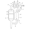
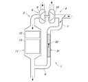
図1は、本発明による排気ガス還流装置の一例を示す模式図である。この排気ガス還流装置1は、内燃機関(ディーゼルエンジン)に設けられて、内燃機関の排気系3と吸気系4とを連通して、排気系3の排気を排気還流ガスとして吸気系4に還流するものであり、排気還流ガス内に含まれる異物粒子の通り抜けを抑制する異物通過抑制部5と、その上流側及び下流側の管路6・7とで排気還流通路が形成されている。
FIG. 1 is a schematic view showing an example of an exhaust gas recirculation device according to the present invention. The exhaust
さらにここでは、吸気過給装置8が設けられており、排気ガス還流装置1は、吸気過給装置8のタービン9の下流側から取り出された排気ガスを排気還流ガスとして、コンプレッサ10の上流側に送入する、いわゆる低圧EGRの排気還流通路が形成されている。
Further, here, an intake
排気系3では、吸気過給装置8のタービン9の下流側に排気浄化装置11が設けられており、この排気浄化装置11の下流側の分流部から、排気還流ガスとなる排気ガスが取り出されて排気ガス還流装置1の異物通過抑制部5に導入される。排気浄化装置11は、ディーゼル酸化触媒(DOC)12と、ディーゼル排気微粒子除去フィルタ(DPF)13とを備える。この排気浄化装置11は、中心軸線がほぼ鉛直方向となるように配置され、内部を排気ガスが下向きに流通する。
In the
排気浄化装置11の下流側の排気には、排気浄化装置11の構成部品の欠損物などが含まれ、排気浄化装置11の上流に比べて、比較的大きな異物粒子が排気還流ガスに混入する可能性が高く、後述するように異物通過抑制部5を構成することで、吸気系4に支障がある所定粒径以上の異物粒子の通り抜けを確実に抑制することができるため、排気浄化装置11の下流側から排気還流ガスとなる排気を取り出すようにしても特に支障はない。
The exhaust on the downstream side of the
また、この排気ガス還流装置1では、吸気過給装置8のコンプレッサ10の上流側の合流部で、異物通過抑制部5を流通した排気還流ガスが送入されるようになっている。この場合、薄肉状に形成されたコンプレッサ10のブレードが、排気還流ガス中に混入する異物で損傷を受ける可能性が考えられるが、後述するようにコンプレッサ10に損傷を与えることのない異物粒子の最大粒径を定め、この粒径以上の異物粒子の通り抜けを阻止することで、コンプレッサ10の損傷を確実に防ぐことができる。
Further, in the exhaust
異物通過抑制部5において、吸気系4にとって有害な所定粒径以上の異物粒子の通り抜けを抑制するには、少なくとも排気還流ガスの最大流量時に、所定粒径以上の異物粒子を異物通過抑制部5内に停留させる、すなわち異物通過抑制部5内で所定粒径以上の異物粒子を減速させ且つ静止させれば良く、この条件が満たされれば、最大流量時でも所定粒径以上の異物粒子が吸気系4に流入することがなく、また、排気還流ガスの流量が最大流量より小さい運転状態では異物粒子が自重で落下するようになる。
In order to suppress the passage of foreign particles larger than a predetermined particle size harmful to the
なお、異物通過抑制部5内を落下する異物粒子は、ガス流入口15から上流側の管路6を通って排気系3の管路に流入して排気ガスと共に放出されるために、特に捕集部を設ける必要はない。
It should be noted that the foreign particles falling in the foreign matter
異物通過抑制部5は、ガス流入口15が下側に、ガス流出口16が上側にそれぞれ配置され、上向き流れで排気還流ガスを流通させるようになっており、重力が異物粒子を減速させる向きに作用する。なお、この異物通過抑制部5では、異物粒子を減速させる向きに重力が作用すれば良く、排気還流ガスの流向は、鉛直方向上向きに限定されず、鉛直方向に対して傾斜していても良い。
The foreign substance
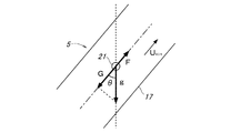
図2は、図1に示した異物通過抑制部5内での異物粒子に作用する外力の状況を示す模式図である。異物粒子21は、排気還流ガスから受ける抵抗力Fにより流れに追随して移動しようとし、このガス流れから受ける抵抗力Fが、重力による減速力Gより小さくなり、異物粒子21の負の加速度が生じるときに、異物粒子21は減速する。このため、異物粒子21を減速させるには、ガス流れから受ける抵抗力Fが重力による減速力Gより小さくなる状態とすれば良い。
FIG. 2 is a schematic diagram showing a situation of an external force acting on the foreign particles in the foreign matter
ここで、異物粒子21がガス流れから受ける抵抗力Fはガス流速UEGRと正の相関関係となり、ガス流速UEGRを低くすることでガス流れから受ける抵抗力Fを小さくすることができる。そこで、ガス流れから受ける抵抗力Fが重力による減速力Gと釣り合うときのガス流速を最高ガス流速UEGR Maxとして定め、異物通過抑制部内のガス流速を最高ガス流速UEGR Max以下に抑えれば、異物粒子21を減速させることができる。
Here, the resistance force F
特にここでは、図1に示したように、異物通過抑制部5内のガス流速UEGRを低下させるために、上流側及び下流側の管路6・7より流路断面積が拡大された拡大断面部(流速抑制手段)17が設けられており、ガス流速を最高ガス流速UEGR Max以下に抑えるために必要な流路断面積の最小値として最小流路断面積Aminを設定し、この最小流路断面積Amin以上となるように拡大断面部17を形成することで、ガス流速を最高ガス流速以下に抑えて異物粒子を減速させることができる。このとき、最小流路断面積Aminを、最大ガス流量時のガス流速に基づいて求めれば、最大ガス流量時でも異物粒子を減速させることが可能となる。
In particular, as shown in FIG. 1, in order to reduce the gas flow rate U EGR in the foreign matter
また、図2の例では、異物通過抑制部5を、そのガス流れ方向軸線が鉛直方向に対して角度θだけ傾斜した状態となるように配置しており、この場合、異物粒子21には、ガス流れ方向軸線と鉛直方向とのなす傾斜角度θ(0°≦θ<90°)に応じた重力の流れ方向成分が減速力として作用し、この重力の流れ方向成分Gが、異物粒子21がガス流れから受ける抵抗力Fより大となることで、異物粒子21を減速させることができる。なお、傾斜角度θ=0°とすれば、ガス流れ方向が鉛直方向となる。
Further, in the example of FIG. 2, the foreign substance
以下に、異物通過抑制部5内で異物粒子21を重力の作用で減速させることが可能な条件について、数式を用いて説明する。
Below, the conditions under which the
まず、異物粒子21がガス流れから受ける抵抗力F[N]は、抵抗係数Cd、投影面積Ad[m2]、及び排気還流ガスに対する異物粒子21の相対速度U[m/s]から、以下の式1で与えられる。
ここで、抵抗係数Cdは、流れの中にある粒子のレイノルズ数Redにより異なり、Putnamの提案する公式である次の式2・式3にしたがって、ガスの密度ρG[kg/m3]、粒径(粒子の直径)Dd[m]、及びガスの粘性係数μ[Pa−s]から求められる。
また、ガス流速UEGR[m/s]は、次の式4にしたがって、ガス流量GEGR[kg/s]、一般ガス定数R[J/kg−K]、ガス温度T[K]、ガス圧力P[Pa]、及び拡大断面部17の流路断面積A[m2]から求められる。
一方、異物粒子21が受ける重力の流れ方向成分G[N]は、粒子密度ρd[kg/m3]、粒子体積Vd[m3]、及び重力加速度g[m/s2]、流れ方向の鉛直方向に対する傾斜角度θから、次の式5で与えられる。
![]()
![]()
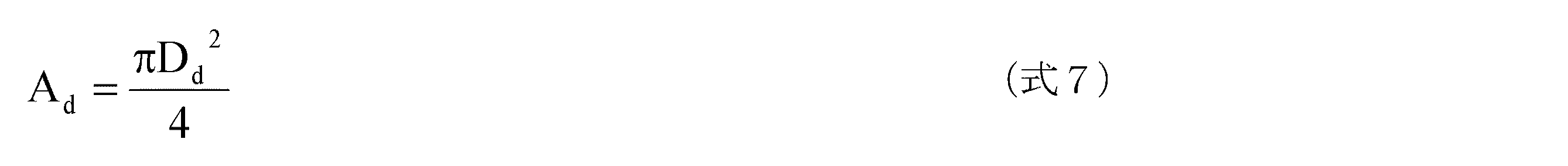
また、計算の簡略化のため異物粒子21を球体と仮定した場合、投影面積Adは、異物粒子21の粒径Ddより次の式7で与えられる。
このようにして異物通過抑制部内で異物粒子を重力の作用で減速させる条件、すなわち重力の流れ方向成分が、異物粒子が排気還流ガスから受ける抵抗力より大となる条件を満たすガス流速UEGRの上限値である最高ガス流速UEGR Maxを、異物粒子の粒径Dd、及び流れ方向の鉛直方向に対する傾斜角度θに応じて求めることができる。 In this way, the condition of decelerating the foreign particles by the action of gravity in the foreign matter passage suppressing portion, that is, the gas flow velocity U EGR that satisfies the condition that the gravity flow direction component is larger than the resistance force that the foreign particles receive from the exhaust gas recirculation gas. the maximum gas flow speed U EGR Max is the upper limit value, the particle diameter D d of foreign particles, and can be determined according to the inclination angle θ with respect to the vertical direction of the flow direction.
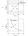
図3は、図1に示した異物通過抑制部5内で異物粒子を重力の作用で減速させることの可能な条件を示している。図3(A)は、異物粒子を重力の作用で減速させることの可能な、粒径Dd[μm]とガス流速UEGR[m/s]との関係を示し、前記の関係式を元にして求められる。なお、ここでは、ガス流れ方向の鉛直方向に対する傾斜角度θ=0、すなわちガス流れ方向を鉛直方向としている。
FIG. 3 shows conditions under which foreign particles can be decelerated by the action of gravity in the foreign matter
この図3(A)では、ガス流速UEGRが最高ガス流速ラインより小さくなるOK領域で、重力の作用による異物粒子の減速が可能となり、この異物粒子の減速が可能な上限となる最高ガス流速UEGR Maxは、異物粒子の粒径Ddが大きくなるのに応じて増大する。例えば、吸気系に支障のない粒径の上限値Dd Max=200[μm]として、この粒径Dd Max以上の異物粒子の通過を抑制するには、ガス流速を最高ガス流速UEGR Max=0.38[m/s]以下に設定すれば良い。 In FIG. 3A, in the OK region where the gas flow rate U EGR is smaller than the maximum gas flow rate line, it is possible to decelerate foreign particles by the action of gravity, and the maximum gas flow rate that is the upper limit at which this foreign particle can be decelerated. U EGR Max increases as the particle size D d of the foreign particle increases. For example, when the upper limit value D d Max = 200 [μm] of the particle size that does not affect the intake system is set, in order to suppress the passage of foreign particles having a particle size D d Max or more, the gas flow rate is set to the maximum gas flow rate U EGR Max. = 0.38 [m / s] or less may be set.
図3(B)は、異物粒子を重力の作用で減速させることの可能な、異物粒子の粒径Ddと、拡大断面部17の流路断面積Aとの関係を示し、図3(A)に示した最高ガス流速UEGR Maxによる最高ガス流速ラインに基づいて、拡大断面部17の流路断面積Aとガス流速UEGRとの関係を示す式4を用いて求められる。
FIG. 3 (B) shows the relationship between the particle size D d of the foreign particle and the cross-sectional area A of the enlarged
この図3(B)では、拡大断面部17の流路断面積Aが最小流路断面積ラインより大きくなるOK領域で、重力の作用による異物粒子の減速が可能となり、この異物粒子の減速が可能な下限となる最小流路断面積Aminは、異物粒子の粒径Ddが大きくなるのに応じて小さくなる。例えば、粒径Dd Max=200[μm]以上の異物粒子の通過を抑制するには、拡大断面部17を最小流路断面積Amin=0.03[m2]以上に設定すれば良い。このとき、最小流路断面積Aminを、最大ガス流量時のガス流速に基づいて求めれば、最大ガス流量時でも異物粒子を減速させることが可能となる。
In FIG. 3B, in the OK region where the flow passage cross-sectional area A of the enlarged
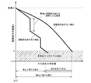
図4は、図1に示した異物通過抑制部5内で異物粒子が減速して静止するまでの状況を示している。これは、図2に示したように、ガス流れから受ける抵抗力Fと重力による減速力Gとの合力が負になるよう設定した場合であり、このような場合、異物粒子は、負の合力の大きさに応じて定まる負の加速度に応じて、速度vが次第に低下して0となる、すなわち静止し、この静止するまでに要するガス流れ方向長さを異物通過抑制部5に確保することで、異物粒子を異物通過抑制部5内で静止させて、異物粒子の通り抜けを抑制することができる。
FIG. 4 shows a situation in which the foreign particles are decelerated and stopped in the foreign matter
異物粒子が静止するまでに要するガス流れ方向長さLは、異物粒子に生じる負の加速度と、ガス流入口から突入した際の異物粒子の流入初速v0に応じて定まり、この異物粒子に生じる負の加速度と異物粒子の流入初速v0とに基づいて、異物粒子を静止させることの可能な流れ方向長さの最小値を最小流れ方向長さLminとして設定し、この最小流れ方向長さLmin以上となるように拡大断面部17を形成することで、異物粒子を静止させることができる。このとき、最小流れ方向長さLminを、最大ガス流量時の異物粒子の流入初速、すなわち最高流入初速v0Maxに基づいて求めれば、最大ガス流量時でも異物粒子を静止させることが可能となり、異物粒子の通り抜けを確実に抑制することができる。
The length L in the gas flow direction required until the foreign particles come to rest is determined according to the negative acceleration generated in the foreign particles and the initial velocity v0 of the foreign particles when entering from the gas inlet, and the negative length generated in the foreign particles. based of the inflow initial speed v0 of the acceleration and foreign particles, the minimum possible flow direction length of be stationary foreign particles set as the minimum flow direction length L min, the minimum flow direction length L min By forming the enlarged
以上のように、拡大断面部17によりガス流速を最高ガス流速以下に抑えることで、異物粒子を減速させることができ、さらに、拡大断面部17を最小流れ方向長さ以上に亙って設けることで、異物粒子を拡大断面部17内で静止させることができ、これにより、所定粒径以上の異物粒子が異物通過抑制部5を通り抜けて吸気系に流入することを確実に抑制することができる。
As described above, by suppressing the gas flow rate to the maximum gas flow rate or less by the enlarged
また、図1に示したように、異物通過抑制部5は、ガス流入口15における排気還流ガスの主流ベクトルの延長線上にガス流出口16が位置するように形成されている。これにより、異物通過抑制部5内でガス流線が曲折されることがなく、異物通過抑制部5による流路損失を低減することができる。
Further, as shown in FIG. 1, the foreign substance
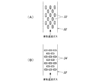
図5は、本発明による排気ガス還流装置の別の例を示す模式図である。図6は、図5に示した流路抵抗部を詳しく示す模式図である。ここでは、異物通過抑制部31に、排気還流ガスの流速を低下させる流路抵抗部(流速抑制手段)32が設けられている。この異物通過抑制部31は、図1の例での異物通過抑制部5のように、上流側及び下流側の管路6・7より流路断面積が拡大された構成とはなっておらず、流路抵抗部32は、図6に示すように、複数の流路抵抗体(フィン)33・34からなる流路抵抗体群を内部に備えている。
FIG. 5 is a schematic view showing another example of the exhaust gas recirculation device according to the present invention. FIG. 6 is a schematic diagram showing in detail the flow path resistance portion shown in FIG. Here, the foreign material
図6(A)に示す例では、流路抵抗体33が、ガス流れ方向に沿う向きに配置されている。図6(B)に示す例は、流路抵抗体34が、ガス流れ方向に直交する向きに配置されている。また、各例での流路抵抗体33・34は、互い違いに千鳥状に配置されている。
In the example shown in FIG. 6A, the
図6(A)の構成では、流量特性が良いが、異物粒子を減速する効果は低くなる。図6(B)の構成では、異物粒子を減速する効果が高くなるが、流量特性は低下する。このように流路抵抗体33・34は、異物粒子を減速する効果を高める上では、ガス流れを遮るように設定するほうが良いが、同時に流量特性も悪化してしまうため、異物粒子の減速効果と流量特性との双方を考慮して、流路抵抗体33・34の配置数や寸法、流路抵抗部32の流れ方向長さを決定すると良い。
In the configuration of FIG. 6A, the flow rate characteristic is good, but the effect of decelerating the foreign particles is low. In the configuration of FIG. 6B, the effect of decelerating the foreign particles is enhanced, but the flow rate characteristic is degraded. As described above, in order to enhance the effect of decelerating the foreign particles, the
流路抵抗部32では、流路抵抗体33・34による圧力損失に応じてガス流量が小さくなることでガス流速UEGRが低下し、このガス流速UEGRの低下量は、流路抵抗係数Krと正の相関関係にあり、流路抵抗係数Krは、流路抵抗体群の構成、すなわち流路抵抗体33・34の配置形態に応じて定まる。そこで、ガス流速を最高ガス流速UEGR Max以下に抑えるために必要な流路抵抗の最小値に対応する最小流路抵抗係数Krminを設定し、この最小流路抵抗係数Krmin以上となるように流路抵抗体33・34を配置することで、ガス流速を最高ガス流速以下に抑えて異物粒子を減速させることができる。このとき、最小流路抵抗係数Krminを、最大ガス流量時のガス流速に基づいて求めれば、最大ガス流量時でも異物粒子を減速させることが可能となる。
In the flow
また、前記の例と同様に、最大流量時でも異物粒子を流路抵抗部32内で静止させるために、流路抵抗部32に流入する異物粒子の最高流入初速v0Maxと、流れ方向の鉛直方向に対する傾斜角度θとに基づいて、前記の例と同様にして、最小流れ方向長さLminを決定し、流路抵抗部32を最小流れ方向長さLmin以上に亙って形成する。
Similarly to the above example, the maximum inflow initial velocity v0 Max of the foreign particles flowing into the flow
このとき、特に流路抵抗部32では、異物粒子が流路抵抗体33・34との衝突によって減速することから、図4に示したように、流路抵抗体33・34がない場合に比較して、流れ方向長さを短くすることができ、流路抵抗体33・34との衝突による減速特性は、流路抵抗体33・34の配置形態に応じて異なる。そこで、ガス流速により規定される最小流れ方向長さLminを、流路抵抗体33・34の配置形態に応じて補正する、例えば、最小流れ方向長さLminに補正係数Kc(Kc≦1)を乗じる補正を行い、これにより得られた最小流れ方向長さLmin以上となるように、流路抵抗部32を形成する。
At this time, particularly in the flow
このように流路抵抗体33・34による減速効果を考慮することで、異物通過抑制部31の流れ方向長さを必要以上に確保することを避けて、異物通過抑制部31の小型化を図ることができる。
In this way, by taking into account the deceleration effect of the
図7は、本発明による排気ガス還流装置の別の例を示す要部模式図である。ここでは、異物通過抑制部41が、拡大断面部兼流路抵抗部42を有し、この拡大断面部兼流路抵抗部42では、図1の例と同様に、上流側及び下流側の管路6・7より流路断面積が拡大され、さらに、図6の例と同様に、内部に流路抵抗体43が配設されている。
FIG. 7 is a schematic diagram of a main part showing another example of the exhaust gas recirculation device according to the present invention. Here, the foreign substance
このようにすると、拡大断面部42と流路抵抗体43との相乗効果により、ガス流速を大幅に抑制することができ、これより異物通過抑制部41の長さを短くして小型化を図ることができる。
If it does in this way, the gas flow velocity can be significantly suppressed by the synergistic effect of the
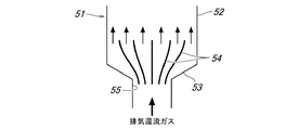
図8は、本発明による排気ガス還流装置の別の例を示す要部模式図である。ここでは、異物通過抑制部51における拡大断面部52の上流側に、流路断面積が漸増する漸拡部53が設けられており、この漸拡部53内には、複数の整流板(ガスガイド)54が、互いの間隙幅が下流側に向かって次第に拡開する態様で設けられている。この整流板54は、円形断面をなし、下流側に向かって径が漸増する筒状に形成されており、複数の整流板54が同心円状に配置されている。
FIG. 8 is a schematic diagram of a main part showing another example of the exhaust gas recirculation device according to the present invention. Here, on the upstream side of the
このようにすると、ガス流入口55から流入した排気還流ガスが、漸拡部53を経て拡大断面部52に至る間に、整流板54により径方向外側に誘導され、これにより拡大断面部52内での排気還流ガスの流れの分布が均一化されるため、流路損失を低減することができ、また、局所的にガス流速が高くなることで異物粒子が通り抜けることを避けることができるため、異物粒子が吸気系に流入することを確実に抑制することができる。
In this way, the exhaust gas recirculation gas flowing in from the
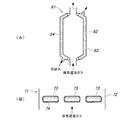
図9は、本発明による排気ガス還流装置の別の例を示す要部模式図である。これらの例は、EGRセパレータとしての異物通過抑制部61・71がEGRクーラを兼用する構成となっている。
FIG. 9 is a schematic diagram of a main part showing another example of the exhaust gas recirculation apparatus according to the present invention. In these examples, the foreign substance
図9(A)に示す例では、異物通過抑制部61の拡大断面部62を筒状に外囲するように、冷却水(冷媒)が流通可能な冷媒流路64を画成するジャケット63が設けられており、拡大断面部62の内部を流通する排気還流ガスを冷却水との熱交換により冷却するようになっている。なお、図示するような拡大断面部を有するものの他、図5・図6の例と同様に、拡大断面部を有しない異物通過抑制部の外周に冷媒流路を形成するジャケットを設けることも可能である。
In the example shown in FIG. 9A, a
図9(B)に示す例では、異物通過抑制部71の流路抵抗部72に配設された流路抵抗体73が、中空に形成されて、その空洞が冷却水(冷媒)が流通可能な冷媒流路74となっており、流路抵抗体73の外側を流通する排気還流ガスを冷却水との熱交換により冷却するようになっている。なお、このような構成は、図6の例のように拡大断面部を有しないものや、図7の例のように拡大断面部を有するもののいずれに適用することも可能である。
In the example shown in FIG. 9B, the flow path resistor 73 disposed in the flow
このようにすると、排気還流ガスの冷却装置を別に設ける必要がなく、排気ガス還流装置がガス流れ方向に長くなることを抑制して、排気ガス還流装置の簡素化及び小型化を図ることができる。さらに、流速抑制手段としての拡大断面部や流路抵抗部では、排気還流ガスの流速が低下することから、ここで排気還流ガスを冷却するようにすると、熱交換効率を高めることができる。 In this way, it is not necessary to provide a separate cooling device for the exhaust gas recirculation gas, and the exhaust gas recirculation device can be prevented from becoming longer in the gas flow direction, and the exhaust gas recirculation device can be simplified and miniaturized. . Furthermore, since the flow velocity of the exhaust gas recirculation gas decreases in the enlarged cross-section portion and the flow path resistance portion as the flow velocity suppressing means, the heat exchange efficiency can be improved by cooling the exhaust gas recirculation gas here.
なお、前記の例では、吸気過給装置を、排気圧力により駆動する、いわゆる排気ターボ過給機としたが、本発明はこれに限定されるものではなく、機械式過給機や電動過給機であっても良い。 In the above example, the intake turbocharger is a so-called exhaust turbocharger that is driven by the exhaust pressure. However, the present invention is not limited to this, and a mechanical supercharger or an electric supercharger is used. It may be a machine.
1 排気ガス還流装置
3 排気系
4 吸気系
5、31、41、51、61、71 異物通過抑制部
6・7 管路
8 吸気過給装置、9 タービン、10 コンプレッサ
11 排気浄化装置
15 ガス流入口、16 ガス流出口
17、52、62 拡大断面部
21 異物粒子
32、72 流路抵抗部
42 拡大断面部兼流路抵抗部
33、34、43、73 流路抵抗体
53 漸拡部
54 整流板
55 ガス流入口
63 ジャケット
64、74 冷媒流路
DESCRIPTION OF
Claims (10)
前記異物通過抑制部に上向き流れで排気還流ガスを流通させると共に、この異物通過抑制部に、所定粒径以上の異物粒子を重力の作用で最大流量時でも減速させることが可能な所定の最高ガス流速以下となるようにガス流速を低下させる流速抑制手段が設けられると共に、この流速抑制手段が、最大流量時でも異物粒子を静止させることが可能な所定の最小流れ方向長さ以上に亙って設けられたことを特徴とする排気ガス還流装置。 An exhaust gas recirculation passage that communicates the exhaust system and the intake system of the internal combustion engine and recirculates the exhaust gas of the exhaust system to the intake system as an exhaust gas recirculation gas. The foreign material particles contained in the exhaust gas recirculation gas are provided in the exhaust gas recirculation passage. An exhaust gas recirculation device provided with a foreign matter passage restraining part for restraining passage through,
The exhaust gas recirculation gas is circulated in an upward flow through the foreign matter passage suppressing portion, and the predetermined maximum gas capable of decelerating foreign particles having a predetermined particle size or more to the foreign matter passage restricting portion even at the maximum flow rate by the action of gravity. A flow rate suppressing means for reducing the gas flow rate is provided so as to be less than or equal to the flow rate, and the flow rate suppressing means extends over a predetermined minimum flow direction length that can keep foreign particles stationary even at the maximum flow rate. An exhaust gas recirculation device provided.
Priority Applications (1)
| Application Number | Priority Date | Filing Date | Title |
|---|---|---|---|
| JP2008320736A JP4966290B2 (en) | 2008-12-17 | 2008-12-17 | Exhaust gas recirculation device for internal combustion engine |
Applications Claiming Priority (1)
| Application Number | Priority Date | Filing Date | Title |
|---|---|---|---|
| JP2008320736A JP4966290B2 (en) | 2008-12-17 | 2008-12-17 | Exhaust gas recirculation device for internal combustion engine |
Publications (2)
| Publication Number | Publication Date |
|---|---|
| JP2010144561A true JP2010144561A (en) | 2010-07-01 |
| JP4966290B2 JP4966290B2 (en) | 2012-07-04 |
Family
ID=42565253
Family Applications (1)
| Application Number | Title | Priority Date | Filing Date |
|---|---|---|---|
| JP2008320736A Expired - Fee Related JP4966290B2 (en) | 2008-12-17 | 2008-12-17 | Exhaust gas recirculation device for internal combustion engine |
Country Status (1)
| Country | Link |
|---|---|
| JP (1) | JP4966290B2 (en) |
Citations (7)
| Publication number | Priority date | Publication date | Assignee | Title |
|---|---|---|---|---|
| JPS59100957U (en) * | 1982-12-26 | 1984-07-07 | トヨタ自動車株式会社 | Dehumidifier for exhaust gas recirculation system |
| JPH01101612U (en) * | 1987-12-28 | 1989-07-07 | ||
| JPH08135518A (en) * | 1994-11-11 | 1996-05-28 | Mazda Motor Corp | Exhaust gas reflux device for engine with supercharger |
| JP2007147119A (en) * | 2005-11-25 | 2007-06-14 | Kawasaki Plant Systems Ltd | Reversing dust removing device with a large number of current plates |
| JP2008150955A (en) * | 2006-12-14 | 2008-07-03 | Denso Corp | Exhaust gas recirculating device |
| JP2008534835A (en) * | 2005-03-24 | 2008-08-28 | エミテック ゲゼルシヤフト フユア エミツシオンス テクノロギー ミツト ベシユレンクテル ハフツング | Exhaust device provided with exhaust treatment device and heat exchanger in exhaust return path |
| JP2009299476A (en) * | 2008-06-10 | 2009-12-24 | Toyota Motor Corp | Foreign matter removal device for internal combustion engine |
-
2008
- 2008-12-17 JP JP2008320736A patent/JP4966290B2/en not_active Expired - Fee Related
Patent Citations (7)
| Publication number | Priority date | Publication date | Assignee | Title |
|---|---|---|---|---|
| JPS59100957U (en) * | 1982-12-26 | 1984-07-07 | トヨタ自動車株式会社 | Dehumidifier for exhaust gas recirculation system |
| JPH01101612U (en) * | 1987-12-28 | 1989-07-07 | ||
| JPH08135518A (en) * | 1994-11-11 | 1996-05-28 | Mazda Motor Corp | Exhaust gas reflux device for engine with supercharger |
| JP2008534835A (en) * | 2005-03-24 | 2008-08-28 | エミテック ゲゼルシヤフト フユア エミツシオンス テクノロギー ミツト ベシユレンクテル ハフツング | Exhaust device provided with exhaust treatment device and heat exchanger in exhaust return path |
| JP2007147119A (en) * | 2005-11-25 | 2007-06-14 | Kawasaki Plant Systems Ltd | Reversing dust removing device with a large number of current plates |
| JP2008150955A (en) * | 2006-12-14 | 2008-07-03 | Denso Corp | Exhaust gas recirculating device |
| JP2009299476A (en) * | 2008-06-10 | 2009-12-24 | Toyota Motor Corp | Foreign matter removal device for internal combustion engine |
Also Published As
| Publication number | Publication date |
|---|---|
| JP4966290B2 (en) | 2012-07-04 |
Similar Documents
| Publication | Publication Date | Title |
|---|---|---|
| CN101512122B (en) | Integration of exhaust air coolers in turbochargers | |
| CN104302892B (en) | There is the gas turbine unit of exhaust gas recirculatioon | |
| CN103184917B (en) | Waste gas treatment equipment | |
| JP2009524775A (en) | Unit for reintroducing low-pressure EGR condensate at / before the compressor | |
| JP5263191B2 (en) | Fluid filtration cooling device for internal combustion engine | |
| JP6119110B2 (en) | Low pressure loop EGR device | |
| JP5141585B2 (en) | Foreign matter collecting device with cooler | |
| JP4966290B2 (en) | Exhaust gas recirculation device for internal combustion engine | |
| JP6263928B2 (en) | Condensate separator | |
| JPH09250894A (en) | Heat exchanger | |
| US9581064B2 (en) | Truck provided with a device for lowering the temperature of exhaust gas | |
| CN107304733B (en) | Exhaust system for vehicle and control method thereof | |
| JP2022104200A (en) | Gas-liquid separator | |
| JP2010242662A (en) | Foreign matter collecting device for low pressure EGR passage | |
| JP5413221B2 (en) | Exhaust gas recirculation device | |
| JP7375636B2 (en) | intercooler | |
| JP6730175B2 (en) | EGR cooler | |
| JP2010169013A (en) | Egr device for internal combustion engine | |
| JP2010156272A (en) | Egr device and egr filter of internal combustion engine | |
| JP2007224802A (en) | Exhaust recirculating device of turbo-compound engine | |
| JP6508302B2 (en) | Engine exhaust system | |
| JP7306307B2 (en) | intercooler | |
| KR101172065B1 (en) | Intercooler | |
| JP2011064163A (en) | Egr diffusion unit | |
| JP6550981B2 (en) | EGR cooler and EGR system for internal combustion engine |
Legal Events
| Date | Code | Title | Description |
|---|---|---|---|
| A621 | Written request for application examination |
Free format text: JAPANESE INTERMEDIATE CODE: A621 Effective date: 20101125 |
|
| RD02 | Notification of acceptance of power of attorney |
Free format text: JAPANESE INTERMEDIATE CODE: A7422 Effective date: 20110924 |
|
| A977 | Report on retrieval |
Free format text: JAPANESE INTERMEDIATE CODE: A971007 Effective date: 20111124 |
|
| A131 | Notification of reasons for refusal |
Free format text: JAPANESE INTERMEDIATE CODE: A131 Effective date: 20111129 |
|
| A521 | Written amendment |
Free format text: JAPANESE INTERMEDIATE CODE: A523 Effective date: 20120126 |
|
| TRDD | Decision of grant or rejection written | ||
| A01 | Written decision to grant a patent or to grant a registration (utility model) |
Free format text: JAPANESE INTERMEDIATE CODE: A01 Effective date: 20120321 |
|
| A01 | Written decision to grant a patent or to grant a registration (utility model) |
Free format text: JAPANESE INTERMEDIATE CODE: A01 |
|
| A61 | First payment of annual fees (during grant procedure) |
Free format text: JAPANESE INTERMEDIATE CODE: A61 Effective date: 20120330 |
|
| R150 | Certificate of patent or registration of utility model |
Free format text: JAPANESE INTERMEDIATE CODE: R150 |
|
| FPAY | Renewal fee payment (event date is renewal date of database) |
Free format text: PAYMENT UNTIL: 20150406 Year of fee payment: 3 |
|
| LAPS | Cancellation because of no payment of annual fees |