JP2010144544A - Suction noise amplifier - Google Patents
Suction noise amplifier Download PDFInfo
- Publication number
- JP2010144544A JP2010144544A JP2008320435A JP2008320435A JP2010144544A JP 2010144544 A JP2010144544 A JP 2010144544A JP 2008320435 A JP2008320435 A JP 2008320435A JP 2008320435 A JP2008320435 A JP 2008320435A JP 2010144544 A JP2010144544 A JP 2010144544A
- Authority
- JP
- Japan
- Prior art keywords
- intake
- intake passage
- forming wall
- resonance
- chamber forming
- Prior art date
- Legal status (The legal status is an assumption and is not a legal conclusion. Google has not performed a legal analysis and makes no representation as to the accuracy of the status listed.)
- Pending
Links
- 238000011144 upstream manufacturing Methods 0.000 claims description 9
- 238000002485 combustion reaction Methods 0.000 claims description 5
- 230000015572 biosynthetic process Effects 0.000 description 3
- 230000000694 effects Effects 0.000 description 2
- 230000010349 pulsation Effects 0.000 description 2
- 239000011347 resin Substances 0.000 description 2
- 229920005989 resin Polymers 0.000 description 2
- 230000003434 inspiratory effect Effects 0.000 description 1
- 239000000463 material Substances 0.000 description 1
- 238000000926 separation method Methods 0.000 description 1
- 230000003584 silencer Effects 0.000 description 1
- 238000003466 welding Methods 0.000 description 1
Images

Landscapes
- Exhaust Silencers (AREA)
Abstract
Description
本発明は、内燃機関の吸気系に配置され内部に吸気通路を形成するエアダクトに設けられる吸気音増幅器に関する。 The present invention relates to an intake sound amplifier provided in an air duct that is disposed in an intake system of an internal combustion engine and forms an intake passage therein.
従来、車室内における静粛性のみが重視されていたため、騒音源のひとつである吸気系においてもレゾネータ(消音器)を設けるなどして積極的に吸気騒音を低減させていた。
しかしながら、近年、静粛性を保ちながら逆にわざと音を出して“心地よい音”を得たいとする動きが高まり、吸気騒音においても狙いの周波数での音を増幅・強調する要求が高まっている。
Conventionally, since only the quietness in the passenger compartment has been emphasized, the intake noise has been actively reduced by providing a resonator (silencer) in the intake system which is one of the noise sources.
In recent years, however, there has been an increase in the movement to intentionally produce a “comfortable sound” while maintaining quietness, and there is an increasing demand for amplifying and emphasizing the sound at the target frequency in the intake noise.
狙いの周波数での音を増幅・強調する吸気音増幅器は、例えば、特許文献1〜3に開示されている。特許文献1〜3開示の吸気音増幅器は、吸気脈動により振動する振動体(振動版、弾性体)を設けて音を増幅・強調している。
Inspiratory sound amplifiers that amplify and emphasize sound at a target frequency are disclosed in
しかし、従来の吸気音増幅器には、次の問題点がある。
吸気脈動により振動する振動体を設けているため、吸気音増幅器の構造が複雑化しやすい。
Since a vibrating body that vibrates due to intake pulsation is provided, the structure of the intake sound amplifier tends to be complicated.
本発明の目的は、従来に比べて構造を簡素化できる吸気音増幅器を提供することにある。 An object of the present invention is to provide an intake sound amplifier capable of simplifying the structure as compared with the prior art.
上記目的を達成する本発明はつぎの通りである。
(1) 内燃機関の吸気系に配置され内部に吸気通路を形成するエアダクトに設けられる吸気音増幅器であって、
少なくとも一部が前記エアダクトの外側に配置されており、前記吸気通路に連通する共鳴容積室を内側に備える共鳴室形成壁と、
前記共鳴室形成壁の前記吸気通路側端部から前記吸気通路内に突き出して設けられる突起と、
を有する吸気音増幅器。
(2) 前記突起は、前記共鳴室形成壁の前記吸気通路側端部の、前記吸気通路内を流れる吸気の流れ方向下流側部分から、前記吸気通路内を流れる吸気の流れ方向上流側に向って突き出している、(1)記載の吸気音増幅器。
The present invention for achieving the above object is as follows.
(1) An intake sound amplifier provided in an air duct disposed in an intake system of an internal combustion engine and forming an intake passage therein,
A resonance chamber forming wall, at least a part of which is disposed outside the air duct, and provided with a resonance volume chamber communicating with the intake passage;
A protrusion that protrudes into the intake passage from an end portion on the intake passage side of the resonance chamber forming wall;
Intake sound amplifier.
(2) The protrusion extends from a downstream side portion in the flow direction of intake air flowing in the intake passage at an end portion of the resonance chamber forming wall toward the upstream side in the flow direction of intake air flowing in the intake passage. The intake sound amplifier according to (1), which protrudes.
上記(1)の吸気音増幅器によれば、以下の効果を得ることができる。
吸気通路に連通する共鳴容積室を内側に備える共鳴室形成壁と、共鳴室形成壁の吸気通路側端部から吸気通路内に突き出して設けられる突起と、を有するため、吸気通路内を流れる吸気が突起に衝突し、剥離して渦が発生し、該渦が共鳴容積室内に入り、共鳴容積室内の空気を共鳴させることで、音を増幅・強調することができる。
この構造では、従来と異なり振動体を設けていないため、振動体を設ける場合に比べて構造を簡素化できる。
上記(2)の吸気音増幅器によれば、以下の効果を得ることができる。
突起が、共鳴室形成壁の吸気通路側端部の、吸気通路内を流れる吸気の流れ方向下流側部分から、吸気通路内を流れる吸気の流れ方向上流側に向って突き出しているため、突起に衝突し剥離して発生した渦を確実に共鳴容積室内に入れることができる。
According to the intake sound amplifier of (1), the following effects can be obtained.
Since the resonance chamber forming wall having a resonance volume chamber communicating with the intake passage on the inside, and a protrusion provided to protrude from the end of the resonance chamber forming wall into the intake passage, the intake air flowing in the intake passage The vortex collides with the protrusion, peels off, and a vortex is generated. The vortex enters the resonance volume chamber, and the air in the resonance volume chamber is resonated to amplify and emphasize the sound.
In this structure, unlike the conventional case, no vibration body is provided, so that the structure can be simplified as compared with the case where the vibration body is provided.
According to the intake sound amplifier of (2) above, the following effects can be obtained.
Since the protrusion protrudes toward the upstream side in the flow direction of the intake air flowing in the intake passage from the downstream portion in the flow direction of the intake air flowing in the intake passage at the end of the resonance chamber forming wall on the intake passage side. The vortex generated by collision and separation can be reliably placed in the resonance volume chamber.
以下に、本発明実施例の吸気音増幅器を、図1〜図4を参照して、説明する。
本発明実施例の吸気音増幅器10は、自動車用の内燃機関の吸気系に配置され内部に吸気通路1aを形成するエアダクト(吸気ダクト、ダクト)1に設けられる。
Hereinafter, an intake sound amplifier according to an embodiment of the present invention will be described with reference to FIGS.
An
エアダクト1は、内燃機関の、吸気流れ方向上流側に配置される吸気系のダクトである。エアダクト1は、図示略のエアクリーナの上流側のダクトであってもよく、エアクリーナの下流側のダクトであってもよい。エアダクト1は、樹脂製でありブロー成形品である。
The
吸気音増幅器10は、変形不能または変形しても無視できる程度しか変形しない材料で構成されており、たとえば樹脂製である。吸気音増幅器10は、共鳴室形成壁11と、突起12と、を有する。
The
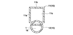
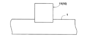
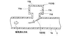
共鳴室形成壁11の少なくとも一部(全体又は略全体)は、エアダクト1の外側に配置されている。共鳴室形成壁11は、側壁11aと底壁11bとからなる。共鳴室形成壁11は、吸気通路1aに連通する共鳴容積室11cを内側に備える。共鳴容積室11cは、共鳴室形成壁11の内側の空間全体であり、側壁11aと底壁11bとで囲まれる空間全体である。共鳴室形成壁11の形状は、図1〜図3に示すように、エアダクト1側に開放する直方体形状であってもよく、図4に示すように、図1〜図3に示す直方体形状の側壁に段差部11dが少なくとも1箇所形成された形状であってもよく、その他の形状(たとえばエアダクト1側のみに開放する有底円筒形状)であってもよい。
At least a part (whole or substantially whole) of the resonance
共鳴室形成壁11は、エアダクト1に固定される。共鳴室形成壁11は、側壁11aのエアダクト1側の端部とエアダクト1とを溶着等することにより、エアダクト1に固定される。
The resonance
突起12は、共鳴室形成壁11に固定されている。突起12は、共鳴室形成壁11と別体に形成されて共鳴室形成壁11に直接又は別部材を介して固定して取付けられていてもよく、共鳴室形成壁11と一体に形成されていてもよい。
The
突起12は、共鳴容積室11cの、吸気通路1aとの連通部分に設けられている。突起12は、共鳴室形成壁11の側壁11aの吸気通路1a側の端部(その近傍を含む)から少なくとも一部が吸気通路1a内に突き出して設けられている。突起12は、共鳴室形成壁11の吸気通路1a側端部の、吸気通路1a内を流れる吸気の流れ方向下流側部分から、吸気通路1a内を流れる吸気の流れ方向上流側に向って突き出している。突起12は、吸気通路1a内を流れる吸気の流れ方向上流側に向って、図3に示すように、吸気通路1a内を流れる吸気の流れ方向と平行な方向に突き出していてもよく、図4に示すように、吸気通路1a内を流れる吸気の流れ方向に対して斜めの方向に突き出していてもよい。突起12は、板状であってもよく、棒状であってもよい。突起12の突き出し方向先端部は、先細り形状(エッジ)とされている(尖っている)。
The
次に、本発明実施例の作用を説明する。
吸気通路1aに連通する共鳴容積室11cを内側に備える共鳴室形成壁11と、共鳴室形成壁11の吸気通路1a側端部から吸気通路1a内に突き出して設けられる尖った突起12と、を有するため、吸気通路1a内を流れる吸気が突起12の先端に衝突し突起12の先端より下流側部分で剥離、渦が発生し、該渦が共鳴容積室11c内に入り、共鳴容積室11c内の空気を共鳴させることで、音を増幅・強調することができる。
この構造では、従来と異なり振動体を設けていないため、振動体を設ける場合に比べて構造を簡素化できる。
Next, the operation of the embodiment of the present invention will be described.
A resonance
In this structure, unlike the conventional case, no vibration body is provided, so that the structure can be simplified as compared with the case where the vibration body is provided.
なお、突起12が、共鳴室形成壁11の吸気通路1a側端部の、吸気通路1a内を流れる吸気の流れ方向上流側部分に設けられている場合、吸気通路1a内を流れる吸気が突起12に衝突し剥離、渦が発生しても、該渦が共鳴容積室11c内に入らず、吸気通路1a内に位置し続けてしまい、共鳴容積室11c内の空気を共鳴させることができず、音を増幅・強調することができない。
しかし、本発明実施例では、突起12が、共鳴室形成壁11の吸気通路1a側端部の、吸気通路1a内を流れる吸気の流れ方向下流側部分から、吸気通路1a内を流れる吸気の流れ方向上流側に向って突き出しているため、突起12に衝突し剥離して発生した渦を確実に共鳴容積室11c内に入れることができる。
In addition, when the
However, in the embodiment of the present invention, the flow of the intake air flowing in the
共鳴室形成壁11の形状、共鳴容積室11cの容積を変更することで、狙いの周波数での音を増幅・強調することができる。
By changing the shape of the resonance
1 エアダクト
1a 吸気通路
10 吸気音増幅器
11 共鳴室形成壁
11a 共鳴室形成壁の側壁
11b 共鳴室形成壁の底壁
11c 共鳴容積室
11d 段差部
12 突起
DESCRIPTION OF
Claims (2)
少なくとも一部が前記エアダクトの外側に配置されており、前記吸気通路に連通する共鳴容積室を内側に備える共鳴室形成壁と、
前記共鳴室形成壁の前記吸気通路側端部から前記吸気通路内に突き出して設けられる突起と、
を有する吸気音増幅器。 An intake sound amplifier provided in an air duct that is disposed in an intake system of an internal combustion engine and forms an intake passage therein,
A resonance chamber forming wall, at least a part of which is disposed outside the air duct, and provided with a resonance volume chamber communicating with the intake passage;
A protrusion that protrudes into the intake passage from an end portion on the intake passage side of the resonance chamber forming wall;
Intake sound amplifier.
Priority Applications (1)
| Application Number | Priority Date | Filing Date | Title |
|---|---|---|---|
| JP2008320435A JP2010144544A (en) | 2008-12-17 | 2008-12-17 | Suction noise amplifier |
Applications Claiming Priority (1)
| Application Number | Priority Date | Filing Date | Title |
|---|---|---|---|
| JP2008320435A JP2010144544A (en) | 2008-12-17 | 2008-12-17 | Suction noise amplifier |
Publications (1)
| Publication Number | Publication Date |
|---|---|
| JP2010144544A true JP2010144544A (en) | 2010-07-01 |
Family
ID=42565236
Family Applications (1)
| Application Number | Title | Priority Date | Filing Date |
|---|---|---|---|
| JP2008320435A Pending JP2010144544A (en) | 2008-12-17 | 2008-12-17 | Suction noise amplifier |
Country Status (1)
| Country | Link |
|---|---|
| JP (1) | JP2010144544A (en) |
Citations (6)
| Publication number | Priority date | Publication date | Assignee | Title |
|---|---|---|---|---|
| JPS578347U (en) * | 1980-06-14 | 1982-01-16 | ||
| JPH04246220A (en) * | 1991-01-31 | 1992-09-02 | Toyoda Gosei Co Ltd | Noise suppressing device |
| JPH08158970A (en) * | 1994-11-30 | 1996-06-18 | Tsuchiya Mfg Co Ltd | Air pipe with resonator |
| JP2003113748A (en) * | 2001-10-04 | 2003-04-18 | Yamaha Motor Co Ltd | Engine intake sound adjustment structure and exhaust sound adjustment structure |
| JP2007170228A (en) * | 2005-12-20 | 2007-07-05 | Nissan Motor Co Ltd | Sound quality transmission structure |
| JP2007332915A (en) * | 2006-06-16 | 2007-12-27 | Toyoda Gosei Co Ltd | Intake sound control structure |
-
2008
- 2008-12-17 JP JP2008320435A patent/JP2010144544A/en active Pending
Patent Citations (6)
| Publication number | Priority date | Publication date | Assignee | Title |
|---|---|---|---|---|
| JPS578347U (en) * | 1980-06-14 | 1982-01-16 | ||
| JPH04246220A (en) * | 1991-01-31 | 1992-09-02 | Toyoda Gosei Co Ltd | Noise suppressing device |
| JPH08158970A (en) * | 1994-11-30 | 1996-06-18 | Tsuchiya Mfg Co Ltd | Air pipe with resonator |
| JP2003113748A (en) * | 2001-10-04 | 2003-04-18 | Yamaha Motor Co Ltd | Engine intake sound adjustment structure and exhaust sound adjustment structure |
| JP2007170228A (en) * | 2005-12-20 | 2007-07-05 | Nissan Motor Co Ltd | Sound quality transmission structure |
| JP2007332915A (en) * | 2006-06-16 | 2007-12-27 | Toyoda Gosei Co Ltd | Intake sound control structure |
Similar Documents
| Publication | Publication Date | Title |
|---|---|---|
| EP1736349B1 (en) | Sound increase apparatus | |
| US8348012B2 (en) | Resonator | |
| JP4993755B2 (en) | Intake sound generator | |
| CN104074642B (en) | Intake sound introducing apparatus | |
| JP5639794B2 (en) | Intake sound generator for internal combustion engine | |
| US20070079784A1 (en) | Sound increase apparatus | |
| US20100212999A1 (en) | Helmholtz resonator | |
| CN104295342B (en) | For the rattler of the anti-noise factor of the exhaust noise and/or air inlet noise that affect Motor vehicles | |
| JP6251353B2 (en) | Sound generator mounted on a vehicle to control vehicle noise | |
| US9374632B2 (en) | Sound generator for an anti-noise system for influencing exhaust noises and/or intake noises of a motor vehicle | |
| US9241211B2 (en) | Tubular body, bass reflex port, and acoustic apparatus | |
| JP2008291775A (en) | Intake sound transmission device for vehicle | |
| US20240166042A1 (en) | Vehicle front structure | |
| DE60136538D1 (en) | SYSTEM COMPRISING A MICROPHONE AND AMPLIFIER | |
| JP6659441B2 (en) | Ventilation duct with silencer | |
| JP2007056841A (en) | Intake sound control structure | |
| JP2010144544A (en) | Suction noise amplifier | |
| JP2005527863A (en) | Device for correcting sounds in automobiles | |
| US8033359B2 (en) | Intake sound adjusting device | |
| CN111508458B (en) | Electronic siren | |
| KR102808016B1 (en) | Acoustic device with resonance structure and method for acoustic tuning according to frequency characteristics thereof | |
| KR20190058364A (en) | Sound generating device as well as vehicle exhaust system | |
| US20050076763A1 (en) | Guitar baffle system | |
| KR101119700B1 (en) | Device for Decreasing Intake Noise of Vehicle | |
| JP2020152335A (en) | Vehicle approach notification device |
Legal Events
| Date | Code | Title | Description |
|---|---|---|---|
| A621 | Written request for application examination |
Free format text: JAPANESE INTERMEDIATE CODE: A621 Effective date: 20111216 |
|
| A977 | Report on retrieval |
Effective date: 20130214 Free format text: JAPANESE INTERMEDIATE CODE: A971007 |
|
| A131 | Notification of reasons for refusal |
Effective date: 20130219 Free format text: JAPANESE INTERMEDIATE CODE: A131 |
|
| A02 | Decision of refusal |
Free format text: JAPANESE INTERMEDIATE CODE: A02 Effective date: 20130702 |