JP2010144533A - Rough idle detecting device of internal combustion engine - Google Patents
Rough idle detecting device of internal combustion engine Download PDFInfo
- Publication number
- JP2010144533A JP2010144533A JP2008319866A JP2008319866A JP2010144533A JP 2010144533 A JP2010144533 A JP 2010144533A JP 2008319866 A JP2008319866 A JP 2008319866A JP 2008319866 A JP2008319866 A JP 2008319866A JP 2010144533 A JP2010144533 A JP 2010144533A
- Authority
- JP
- Japan
- Prior art keywords
- cylinder
- equivalent value
- internal combustion
- combustion engine
- speed
- Prior art date
- Legal status (The legal status is an assumption and is not a legal conclusion. Google has not performed a legal analysis and makes no representation as to the accuracy of the status listed.)
- Pending
Links
Images


Classifications
-
- F—MECHANICAL ENGINEERING; LIGHTING; HEATING; WEAPONS; BLASTING
- F02—COMBUSTION ENGINES; HOT-GAS OR COMBUSTION-PRODUCT ENGINE PLANTS
- F02D—CONTROLLING COMBUSTION ENGINES
- F02D41/00—Electrical control of supply of combustible mixture or its constituents
- F02D41/02—Circuit arrangements for generating control signals
- F02D41/14—Introducing closed-loop corrections
- F02D41/16—Introducing closed-loop corrections for idling
-
- F—MECHANICAL ENGINEERING; LIGHTING; HEATING; WEAPONS; BLASTING
- F02—COMBUSTION ENGINES; HOT-GAS OR COMBUSTION-PRODUCT ENGINE PLANTS
- F02D—CONTROLLING COMBUSTION ENGINES
- F02D41/00—Electrical control of supply of combustible mixture or its constituents
- F02D41/22—Safety or indicating devices for abnormal conditions
-
- F—MECHANICAL ENGINEERING; LIGHTING; HEATING; WEAPONS; BLASTING
- F02—COMBUSTION ENGINES; HOT-GAS OR COMBUSTION-PRODUCT ENGINE PLANTS
- F02D—CONTROLLING COMBUSTION ENGINES
- F02D2200/00—Input parameters for engine control
- F02D2200/02—Input parameters for engine control the parameters being related to the engine
- F02D2200/10—Parameters related to the engine output, e.g. engine torque or engine speed
- F02D2200/1002—Output torque
- F02D2200/1004—Estimation of the output torque
-
- Y—GENERAL TAGGING OF NEW TECHNOLOGICAL DEVELOPMENTS; GENERAL TAGGING OF CROSS-SECTIONAL TECHNOLOGIES SPANNING OVER SEVERAL SECTIONS OF THE IPC; TECHNICAL SUBJECTS COVERED BY FORMER USPC CROSS-REFERENCE ART COLLECTIONS [XRACs] AND DIGESTS
- Y02—TECHNOLOGIES OR APPLICATIONS FOR MITIGATION OR ADAPTATION AGAINST CLIMATE CHANGE
- Y02T—CLIMATE CHANGE MITIGATION TECHNOLOGIES RELATED TO TRANSPORTATION
- Y02T10/00—Road transport of goods or passengers
- Y02T10/10—Internal combustion engine [ICE] based vehicles
- Y02T10/40—Engine management systems
Landscapes
- Engineering & Computer Science (AREA)
- Chemical & Material Sciences (AREA)
- Combustion & Propulsion (AREA)
- Mechanical Engineering (AREA)
- General Engineering & Computer Science (AREA)
- Combined Controls Of Internal Combustion Engines (AREA)
- Electrical Control Of Air Or Fuel Supplied To Internal-Combustion Engine (AREA)
Abstract
【課題】不快な振動を伴うラフアイドル状態か否かを的確に判定することができる高診断精度の内燃機関のラフアイドル検出装置を提供する。
【解決手段】エンジン1のクランク回転速度を検出するクランク角センサ23と、回転速度検出情報に基づいて各気筒2内での燃焼によるクランク回転速度の変動成分を抽出するとともに、抽出した変動成分を積分した仕事量相当値を算出する仕事量相当値算出部32と、各気筒2の膨張行程開始時期における相対的に低速な低速回転領域と、その膨張行程でクランク回転速度が最大速度域に達する高速回転領域とにおけるクランク回転速度の2乗の差から各気筒2での発生トルク相当のトルク相当値を算出するトルク相当値算出部33と、気筒2毎に仕事量相当値およびトルク相当値を対応する判定閾値と比較して、それらの値が判定閾値を下回る気筒2内での燃焼がラフアイドル状態の要因になると判定する異常気筒検出部36とを備える。
【選択図】図1A rough idle detection device for an internal combustion engine with high diagnostic accuracy capable of accurately determining whether or not the engine is in a rough idle state with unpleasant vibrations.
A crank angle sensor for detecting a crank rotation speed of an engine and a fluctuation component of the crank rotation speed due to combustion in each cylinder based on the rotation speed detection information, and the extracted fluctuation component is extracted. A work-equivalent value calculating unit 32 that calculates the integrated work-equivalent value, a relatively low-speed rotation region at the start of the expansion stroke of each cylinder 2, and the crank rotation speed reaches the maximum speed region in the expansion stroke. A torque equivalent value calculation unit 33 for calculating a torque equivalent value corresponding to the torque generated in each cylinder 2 from the square difference of the crank rotation speed with the high speed rotation region, and a work equivalent value and a torque equivalent value for each cylinder 2 An abnormal cylinder detection unit 36 that determines that combustion in the cylinder 2 whose value is below the determination threshold value causes a rough idle state as compared with the corresponding determination threshold value. .
[Selection] Figure 1
Description
本発明は、内燃機関のラフアイドル検出装置、特に燃料噴射量の不足等により内燃機関のアイドル運転時のエンジン回転数が目標回転数に対し不安定に変動するラフアイドル状態を検出する内燃機関のラフアイドル検出装置に関する。 The present invention relates to a rough idle detection device for an internal combustion engine, and more particularly, to an internal combustion engine that detects a rough idle state in which the engine speed during idle operation of the internal combustion engine fluctuates unstablely with respect to a target speed due to insufficient fuel injection amount or the like. The present invention relates to a rough idle detection device.
内燃機関、例えば車両用のエンジンにおいては、アイドル運転時のエンジン回転数(以下、アイドル回転数という)がECU(Electronic Control Unit;電子制御ユニット)で実行されるアイドル回転数制御の目標回転数になるようインジェクタから気筒内への燃料噴射量が制御されるものの、ECUからインジェクタへの指令噴射量に対して実燃料噴射量が不足したりばらついたりすることで、エンジン回転数が目標回転数に対して不安定に変動し、アイドル運転中(例えば冷間始動時)に不快な振動を生じるラフアイドル状態に陥ることがある。そこで、ラフアイドル状態を検出し、ラフアイドル状態を解消する制御を実行できるようにしたものが提案されている。 In an internal combustion engine, for example, a vehicle engine, an engine speed during idle operation (hereinafter referred to as idle speed) is set to a target speed for idle speed control executed by an ECU (Electronic Control Unit). Although the fuel injection amount from the injector to the cylinder is controlled so that the actual fuel injection amount is insufficient or varied with respect to the command injection amount from the ECU to the injector, the engine speed becomes the target speed. On the other hand, it may fluctuate in an unstable manner and fall into a rough idle state that causes unpleasant vibration during idle operation (for example, during cold start). In view of this, there has been proposed a system that detects a rough idle state and can execute control for eliminating the rough idle state.
従来のこの種の内燃機関のラフアイドル検出装置としては、エンジンのアイドル運転時に冷却水温を基に高温再始動されたか否かを判定し、燃料ベーパの発生により実噴射量が不足したり変動したりし易い高温再始動時において、エンジンのオンボード診断システムに備えられる失火カウンタのカウント値がある値を超えるとラフアイドル状態が発生したと判定するようにしたものがあり、この装置では、ラフアイドル状態が発生したと判定したときにアイドル回転数制御の目標回転数を高く設定してラフアイドル状態を解消するようになっている(例えば、特許文献1参照)。 As a conventional rough idle detection device for this type of internal combustion engine, it is determined whether or not the engine has been restarted at a high temperature based on the cooling water temperature during idling of the engine, and the actual injection amount becomes insufficient or fluctuates due to the generation of fuel vapor. At the time of high temperature restart that is easy to perform, there is a device that determines that a rough idle state has occurred when the count value of the misfire counter provided in the on-board diagnostic system of the engine exceeds a certain value. When it is determined that an idle state has occurred, the target rotational speed of the idle rotational speed control is set high to eliminate the rough idle state (see, for example, Patent Document 1).
また、ディーゼルエンジンのアイドル回転数制御時に燃料噴射を複数回のパイロット噴射程度に均等に分割して噴射特性を学習する一方で、一定噴射量以上となる運転状態ではエンジン回転信号パルスを各気筒の燃焼周期に応じて帯域フィルタ相当のフィルタ処理部に取り込み、そのフィルタ処理部において各時点の回転変動成分のみを抽出した瞬時トルク相当値を算出し、その瞬時トルク相当値を積分処理部に取り込んで各気筒の燃焼周期毎の区間で積分することにより各気筒のトルク積算値である気筒別仕事量を気筒毎に算出して、気筒間の噴射特性の相対的なばらつきを学習するものがある(例えば、特許文献2参照)。
しかしながら、従来の内燃機関のラフアイドル検出装置にあっては、失火カウンタのカウント値を利用することで、目標回転数と実回転数の乖離のみからラフアイドル状態か否かを判定するものよりは診断精度が高いものの、不快な振動を伴うラフアイドル状態における気筒毎の燃焼による実回転変動自体を検出するものではなかったため、その診断精度が十分でなかった。そのため、不快な振動を伴うラフアイドル状態に陥っていないにもかかわらず、必要の無い燃料噴射量の増量をラフアイドル解消制御として実行してしまう可能性があり、アイドル安定性および燃費の面で問題があった。 However, in the conventional rough idle detection device for an internal combustion engine, by using the count value of the misfire counter, rather than determining whether or not the engine is in the rough idle state only from the difference between the target rotational speed and the actual rotational speed. Although the diagnostic accuracy is high, the actual rotational fluctuation itself due to the combustion in each cylinder in the rough idle state accompanied by unpleasant vibration was not detected, so the diagnostic accuracy was not sufficient. Therefore, there is a possibility that an unnecessary increase in the fuel injection amount may be executed as rough idle elimination control even though the rough idle state with unpleasant vibration has not occurred. There was a problem.
また、瞬時トルク相当値を各気筒の燃焼周期毎の一定区間で積分するものにあっては、気筒間の噴射特性のばらつきが把握できるものの、膨張行程が前後する気筒についての積分値に同一燃焼での発生トルクの影響が出易いため、不快な振動を伴うラフアイドル状態での各気筒の燃焼による実回転変動を精度良く検出できない場合があり、ラフアイドル状態か否かを的確に判定できる高診断精度を得るためには改善が必要であった。 In addition, in the case where the instantaneous torque equivalent value is integrated over a certain interval for each combustion cycle of each cylinder, the variation in the injection characteristics among the cylinders can be grasped, but the same combustion is made to the integrated value for the cylinders whose expansion stroke is before and after. The actual rotation fluctuation due to combustion of each cylinder in the rough idle state with unpleasant vibrations may not be detected with high accuracy because the torque generated by the engine is likely to be affected. Improvements were needed to obtain diagnostic accuracy.
そこで、本発明は、ラフアイドル状態か否かを的確に判定することができる高診断精度の内燃機関のラフアイドル検出装置を提供することを目的とする。 Therefore, an object of the present invention is to provide a rough idle detection device for an internal combustion engine with high diagnostic accuracy that can accurately determine whether or not the engine is in a rough idle state.
本発明に係る内燃機関のラフアイドル検出装置は、上記目的達成のため、(1)内燃機関のクランク軸の回転速度が目標回転速度に制御されるアイドル運転状態下で前記クランク軸の回転速度が前記目標回転速度に対し変動するラフアイドル状態を検出する内燃機関のラフアイドル検出装置であって、前記内燃機関のクランク軸の回転速度を検出する回転速度検出手段と、前記回転速度検出手段の検出情報に基づいて前記内燃機関の気筒内での燃焼による前記クランク軸の回転速度の変動成分を抽出するとともに、該抽出した変動成分を積分した仕事量相当値を算出する仕事量相当値算出手段と、前記気筒の膨張行程の開始時期における相対的に低速な低速回転領域と、前記気筒の膨張行程で前記クランク軸の回転速度が最大速度域に達する高速回転領域とにおける前記クランク軸の回転速度の2乗の差から前記気筒での発生トルク相当のトルク相当値を算出するトルク相当値算出手段と、前記仕事量相当値および前記トルク相当値をそれぞれに対応する判定閾値と比較して、前記仕事量相当値および前記トルク相当値が前記それぞれに対応する判定閾値を下回るとき前記気筒内での燃焼が前記ラフアイドル状態の要因になると判定する異常気筒判定手段と、を備えたことを特徴とする。 In order to achieve the above object, the rough idle detecting device for an internal combustion engine according to the present invention is: (1) the rotational speed of the crankshaft in an idle operation state in which the rotational speed of the crankshaft of the internal combustion engine is controlled to a target rotational speed; A rough idle detection device for an internal combustion engine that detects a rough idle state that fluctuates with respect to the target rotational speed, the rotational speed detection means for detecting the rotational speed of a crankshaft of the internal combustion engine, and the detection of the rotational speed detection means A work equivalent value calculating means for extracting a fluctuation component of the rotation speed of the crankshaft due to combustion in a cylinder of the internal combustion engine based on the information, and calculating a work equivalent value obtained by integrating the extracted fluctuation component; The rotation speed of the crankshaft reaches the maximum speed range in the relatively low-speed rotation region at the start of the expansion stroke of the cylinder and the expansion stroke of the cylinder. A torque equivalent value calculating means for calculating a torque equivalent value corresponding to the torque generated in the cylinder from a difference in square of the rotation speed of the crankshaft with respect to the high speed rotation region, and the work equivalent value and the torque equivalent value, respectively. In comparison with the determination threshold value corresponding to the abnormal cylinder, it is determined that combustion in the cylinder causes the rough idle state when the work equivalent value and the torque equivalent value are lower than the corresponding determination threshold values. And a determination unit.
この構成により、仕事量相当値およびトルク相当値を基に、内燃機関のラフアイドル状態における各気筒の燃焼による実回転変動を燃焼周期相当の一定周期毎の仕事量の変化および各気筒の燃焼毎の発生トルクの変化として的確に把握することができ、ラフアイドル状態か否かとその要因となる気筒とを的確に判定することができる高診断精度のラフアイドル検出装置となる。しかも、仕事量相当値やトルク相当値がその内燃機関の他の制御のために算出される場合には、計算負荷を増大させることなく高精度のラフアイドル検出が可能になる。 With this configuration, on the basis of the work equivalent value and the torque equivalent value, the actual rotation fluctuation due to the combustion of each cylinder in the rough idle state of the internal combustion engine is changed to the change in the work for every fixed period corresponding to the combustion period and each combustion of each cylinder. Therefore, it is possible to accurately grasp the change in the generated torque of the engine and accurately determine whether or not the engine is in the rough idle state and the cylinder that causes the rough idle detection apparatus. In addition, when the work equivalent value or the torque equivalent value is calculated for other control of the internal combustion engine, it is possible to detect the rough idle with high accuracy without increasing the calculation load.
上記(1)に記載の内燃機関のラフアイドル検出装置においては、(2)前記仕事量相当値算出手段が、前記内燃機関の複数の気筒内での燃焼による前記クランク軸の回転速度の変動成分を気筒毎に抽出し各気筒の燃焼周期毎の一定回転区間で積分して気筒毎の仕事量相当値を予め設定された繰り返し回数だけ繰り返し算出するとともに、該仕事量相当値の算出値を平均化処理した仕事量相当値を算出し、前記トルク相当値算出手段が、各気筒の燃焼周期毎に、各気筒の膨張行程の開始時期における相対的に低速な低速回転領域と、前記各気筒の膨張行程で前記クランク軸の回転速度が最大速度域に達する高速回転領域とにおける前記クランク軸の回転速度の2乗の差から各気筒での発生トルク相当のトルク相当値を前記繰り返し回数だけ繰り返し算出するとともに、該各気筒についてのトルク相当値の算出値を平均化処理したトルク相当値を算出するのが好ましい。 In the rough idle detection device for an internal combustion engine according to (1) above, (2) the work equivalent value calculation means includes a fluctuation component of the rotational speed of the crankshaft due to combustion in a plurality of cylinders of the internal combustion engine. Is extracted for each cylinder and integrated over a constant rotation interval for each combustion cycle of each cylinder, and the work equivalent value for each cylinder is calculated repeatedly for a preset number of repetitions, and the calculated value for the work equivalent value is averaged. The calculated equivalent work value is calculated, and the torque equivalent value calculation means calculates a relatively low speed rotation region at the start timing of the expansion stroke of each cylinder for each combustion cycle of each cylinder, A torque equivalent value corresponding to the torque generated in each cylinder is repeated by the number of repetitions from the difference in square of the rotation speed of the crankshaft in the high speed rotation area where the rotation speed of the crankshaft reaches the maximum speed area in the expansion stroke. To calculate returns, preferably calculates the torque equivalent value a calculated value of the torque equivalent value by averaging for respective cylinders.
この構成により、平均化処理された仕事量相当値およびトルク相当値を基に、内燃機関のアイドル状態における実回転変動をより的確に把握することができ、ラフアイドル状態か否かを高精度に判定することができる高診断精度のラフアイドル検出装置となる。ここにいう平均化処理は、例えば今回算出された算出値と前回の平均化処理で得られた算出値(以下、前回値という)との平均値を算出する、所謂なまし処理であるのがよい。 With this configuration, it is possible to more accurately grasp the actual rotational fluctuation in the idle state of the internal combustion engine based on the averaged work equivalent value and torque equivalent value, and whether or not the engine is in the rough idle state with high accuracy. It becomes a rough idle detection device with high diagnostic accuracy that can be determined. The averaging process here is, for example, a so-called annealing process that calculates an average value of the calculated value calculated this time and the calculated value obtained in the previous averaging process (hereinafter referred to as the previous value). Good.
上記(1)、(2)に記載の内燃機関のラフアイドル検出装置においては、(3)前記異常気筒判定手段が、前記平均化処理された仕事量相当値および前記平均化処理されたトルク相当値が前記それぞれに対応する判定閾値を下回る気筒について、該気筒内での燃焼が前記ラフアイドル状態の要因になることを示す異常検出フラグを設定するのがよい。 In the rough idle detection device for an internal combustion engine according to the above (1) and (2), (3) the abnormal cylinder determination means includes the averaged work equivalent value and the averaged torque equivalent. For cylinders whose values are lower than the corresponding determination threshold values, it is preferable to set an abnormality detection flag indicating that combustion in the cylinder causes the rough idle state.
この構成により、ラフアイドル状態を引き起こす可能性の高い気筒について異常検出フラグが設定されるので、この異常検出フラグを参照することで、ラフアイドル振動に対する検査時等にその要因を迅速に把握することができ、サービス性が向上する。なお、ここにいう異常検出フラグは、そのフラグ設定状態を診断情報としてディーラー等でのメンテナンス時に容易に参照可能にしておくのが望ましく、不揮発性のメモリやバックアップ用メモリに履歴情報として記憶されるようにしてもよい。 With this configuration, an abnormality detection flag is set for a cylinder that is likely to cause a rough idle state. By referring to this abnormality detection flag, the cause can be quickly grasped at the time of inspection for rough idle vibration. Serviceability is improved. The abnormality detection flag mentioned here is preferably stored as history information in a nonvolatile memory or a backup memory so that the flag setting state can be easily referred to as diagnostic information during maintenance at a dealer or the like. You may do it.
上記(1)〜(3)に記載の内燃機関のラフアイドル検出装置においては、(4)前記内燃機関のラフアイドル状態の検出処理を実行するための条件として予め設定された前提条件が成立するか否かを判定する前提条件判定手段を備え、前記前提条件が成立するとき、前記仕事量相当値算出手段および前記異常気筒判定手段が、それぞれの処理を実行するのが好ましい。 In the rough idle detection device for an internal combustion engine according to the above (1) to (3), (4) a precondition set in advance as a condition for executing the rough idle state detection process of the internal combustion engine is satisfied. It is preferable that a precondition determination unit for determining whether or not the precondition is satisfied, and when the precondition is satisfied, the work equivalent value calculation unit and the abnormal cylinder determination unit execute the respective processes.
この構成により、ラフアイドル状態の検出処理を実行するための前提条件が成立したときにのみ、その検出処理が実行されることから、ラフアイドル状態の検出処理を担う計算用資源を通常運転時に必要になる他の算出処理に割り当てることができ、計算用資源を有効活用できる。 With this configuration, since the detection process is executed only when the preconditions for executing the rough idle state detection process are satisfied, the computing resources responsible for the rough idle state detection process are required during normal operation. Can be allocated to other calculation processes, and the computational resources can be used effectively.
上記(4)に記載の内燃機関のラフアイドル検出装置においては、(5)前記前提条件は、前記内燃機関の気筒毎に設けられた燃料噴射弁の噴射特性を学習する学習処理の実行条件が満足されていること、アクセル開度が最小値であること、前記内燃機関を動力源とする車両の車速がゼロであること、前記内燃機関の冷間始動時のアイドル回転数が暖機完了時のアイドル回転数より高回転数に設定されるアイドルアップ制御が実行されていないこと、の各条件を含むものであるのが好ましい。 In the rough idle detection device for an internal combustion engine described in (4) above, (5) the precondition is that an execution condition of a learning process for learning an injection characteristic of a fuel injection valve provided for each cylinder of the internal combustion engine. Satisfaction is satisfied, the accelerator opening is the minimum value, the vehicle speed of the vehicle powered by the internal combustion engine is zero, and the idling speed at the cold start of the internal combustion engine is when the warm-up is completed It is preferable that the conditions include that the idle-up control set to a higher rotational speed than the idle rotational speed is not executed.
この構成により、外乱要因を抑えたほぼ一定条件下で、アイドル回転数の変動を精度良く算出できる。 With this configuration, it is possible to accurately calculate the fluctuation of the idle rotation speed under a substantially constant condition in which the disturbance factor is suppressed.
上記(5)に記載の内燃機関のラフアイドル検出装置においては、(6)前記前提条件は、前記内燃機関の補機負荷が切り替えられていないこと、および、前記車両に搭載され前記内燃機関に駆動連結される変速機がニュートラル状態であること、のうち少なくとも一方の各条件を含むものであってもよい。 In the rough idle detection device for an internal combustion engine according to the above (5), (6) the precondition is that an auxiliary machine load of the internal combustion engine is not switched, and that the internal combustion engine mounted on the vehicle is installed in the internal combustion engine. It may include at least one of the conditions for the drive-coupled transmission to be in the neutral state.
この構成により、外乱要因を更に抑えたほぼ一定条件下で、アイドル回転数の変動を精度良く算出できる。 With this configuration, it is possible to accurately calculate fluctuations in the idle speed under substantially constant conditions in which disturbance factors are further suppressed.
上記(4)に記載の内燃機関のラフアイドル検出装置においては、(7)前記内燃機関がコモンレール式の多気筒のディーゼル機関であり、前記前提条件は、前記ディーゼル機関の前記燃料噴射弁により実行される燃料噴射条件の切り替えが禁止されていること、を含むものであっても好ましい。 In the rough idle detection device for an internal combustion engine described in (4) above, (7) the internal combustion engine is a common-rail multi-cylinder diesel engine, and the precondition is executed by the fuel injection valve of the diesel engine. It is also preferable to include that the switching of the fuel injection conditions to be performed is prohibited.
この構成により、外乱要因をより確実に抑えた一定条件下で、アイドル回転数の変動を精度良く算出できる。 With this configuration, it is possible to accurately calculate the fluctuation of the idle speed under a certain condition in which the disturbance factor is more reliably suppressed.
上記(7)に記載の内燃機関のラフアイドル検出装置においては、(8)前記仕事量相当値算出手段と前記トルク相当値算出手段とが、前記回転速度検出手段の検出情報を前記内燃機関の気筒数に対応する一定の周期であって互いに異なる回転位相で取り込むのが好ましい。 In the rough idle detection device for an internal combustion engine according to (7), (8) the work equivalent value calculation means and the torque equivalent value calculation means use the detection information of the rotation speed detection means as the detection information of the internal combustion engine. It is preferable to take in at a constant cycle corresponding to the number of cylinders and at different rotational phases.
この構成により、仕事量相当値とトルク相当値をそれぞれの算出に最適なタイミングで精度良く算出でき、しかも、両算出手段に用いられる計算用の資源の処理負荷の集中を回避できる。 With this configuration, the work equivalent value and the torque equivalent value can be accurately calculated at the optimum timing for each calculation, and the concentration of the processing load of the calculation resources used in both calculation means can be avoided.
上記(7)、(8)に記載の内燃機関のラフアイドル検出装置においては、(9)前記異常気筒判定手段が、前記仕事量相当値および前記トルク相当値をそれぞれに対応する判定閾値と比較して前記ラフアイドル状態か否かの判定を実行する第1の判定モードと、前記仕事量相当値および前記トルク相当値のうちいずれか片方の値のみをそれに対応する判定閾値と比較して前記ラフアイドル状態か否かの判定を実行する第2の判定モードとに切り替え可能であるのが好ましい。 In the rough idle detection device for an internal combustion engine according to the above (7) and (8), (9) the abnormal cylinder determination means compares the work equivalent value and the torque equivalent value with the corresponding determination threshold values. The first determination mode for determining whether or not the rough idle state, and comparing only one of the work equivalent value and the torque equivalent value with a corresponding determination threshold value, and It is preferable to be able to switch to the second determination mode for determining whether or not the engine is in the rough idle state.
この構成により、仕事量相当値およびトルク相当値を共に算出する場合と、仕事量相当値およびトルク相当値のうちいずれか片方のみを算出する場合とのそれぞれに対応可能な装置となり、各種仕様の内燃機関のラフアイドル検出装置に採用可能となる。 With this configuration, it becomes a device that can handle both the case where both the work equivalent value and the torque equivalent value are calculated, and the case where only one of the work equivalent value and the torque equivalent value is calculated. The present invention can be employed in a rough idle detection device for an internal combustion engine.
本発明によれば、内燃機関のラフアイドル状態における実回転変動を仕事量相当値およびトルク相当値の双方を基に燃焼周期相当の一定周期毎の仕事量の変化および各気筒の燃焼毎の発生トルクの変化として的確に把握することができ、ラフアイドル状態か否かを的確に判定することができる高診断精度の内燃機関のラフアイドル検出装置を提供することができる。 According to the present invention, the actual rotational fluctuation in the rough idling state of the internal combustion engine is determined based on both the work equivalent value and the torque equivalent value. It is possible to provide a rough idle detection device for an internal combustion engine with high diagnostic accuracy that can be accurately grasped as a change in torque and can accurately determine whether or not the engine is in a rough idle state.
以下、本発明の好ましい実施の形態について、図面を参照しつつ説明する。 Hereinafter, preferred embodiments of the present invention will be described with reference to the drawings.
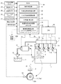
図1は、本発明の一実施形態に係る内燃機関のラフアイドル検出装置を備えた燃料噴射システムの概略構成図であり、図2は、一実施形態に係る内燃機関のラフアイドル検出装置で実行される2種類の回転速度検出期間の説明図である。 FIG. 1 is a schematic configuration diagram of a fuel injection system including a rough idle detection device for an internal combustion engine according to an embodiment of the present invention, and FIG. 2 is executed by the rough idle detection device for an internal combustion engine according to an embodiment. It is explanatory drawing of two types of rotation speed detection periods.
まず、構成について説明する。 First, the configuration will be described.
本実施形態の内燃機関のラフアイドル検出装置は、図1に示すように、多気筒の内燃機関、例えば4気筒のディーゼル機関であるエンジン1の複数の気筒2(図1中には1つのみ図示する)に燃料を噴射する燃料噴射システムに装備されている。 As shown in FIG. 1, the rough idle detection device for an internal combustion engine according to the present embodiment includes a plurality of cylinders 2 (only one in FIG. 1) of a multi-cylinder internal combustion engine, for example, a four-cylinder diesel engine. It is equipped with a fuel injection system for injecting fuel (shown).
この燃料噴射システムには、エンジン1で使用される燃料、例えば軽油を貯留する燃料タンク11と、エンジン1からの動力により燃料タンク11中の燃料を汲み上げて吐出するフィードポンプ12と、エンジン1からの動力によりフィードポンプ12から吐出された燃料をさらに高圧に加圧することができる加圧ポンプ15と、調量指令信号入力に応じて開度を変化させる公知の可変絞り要素として構成されるとともにフィードポンプ12と加圧ポンプ15の間に介装され、加圧ポンプ15への燃料の吸入量をその調量指令信号入力に応じて変化させる調量弁13と、加圧ポンプ15により加圧され吐出された燃料を高圧で蓄圧・貯留可能なコモンレール17と、エンジン1の複数の気筒2に対応して設けられた複数、例えば4つの電磁駆動式あるいは圧電駆動式のインジェクタ18と、を備えている。
The fuel injection system includes a
フィードポンプ12は、例えば歯車ポンプで構成される公知の低圧燃料ポンプである。
The
また、調量弁13は、例えばフィードポンプ12からの燃料供給圧がその調量弁体の開弁方向に作用するように構成されており、内部コイルへの非通電時には最大開度に開放され、一方、内部コイルへの通電時にはその通電量である調量指令信号入力に応じて開度を減じることができる可変絞り要素である。
The
なお、フィードポンプ12と調量弁13の間にはフィードポンプ12からの余剰の吐出燃料を燃料タンク11側に戻すことができる図示しないリリーフ弁が設けられている。
A relief valve (not shown) that can return surplus discharged fuel from the
加圧ポンプ15は、詳細な構造を図示しないが、そのポンプハウジング内に、往復移動可能なプランジャと、このプランジャを駆動する入力軸としてのカムシャフト15aと、カムシャフト15aの内端側の偏心カム部分に回転自在に外装されたカムリングとを有する公知のものであり、そのポンプハウジングとプランジャの間に、プランジャの往復移動によって燃料の吸入と加圧および吐出作業とを行なう少なくとも1つの加圧室を画成したものである。この加圧ポンプ15は、図示しない吸入ポート側および吐出ポート側のチェック弁を内蔵しており、加圧ポンプ15からフィードポンプ12側への燃料の逆流が吸入ポート側の逆止弁により阻止されるとともに、コモンレール17から加圧ポンプ15側への燃料の逆流が吐出側のチェック弁により阻止されるようになっている。なお、加圧ポンプ15は、フィードポンプ12と一体となって燃料供給ポンプを構成するものであってもよい。
Although the detailed structure of the pressurizing
コモンレール17は、加圧ポンプ15により加圧され吐出された燃料を負荷やエンジン回転数に依存せずに高圧で蓄圧・貯留し、各インジェクタ18に安定した圧力で燃料を供給することができる蓄圧手段であり、このコモンレール17には、例えばその内部の燃料の圧力である実コモンレール圧を予め設定された上限値までに制限する図示しないリリーフ弁が装着されている。
The
複数のインジェクタ18は、これらの駆動ユニットであるEDU(Electronic Distribution Unit)20に配線接続された電磁弁部18aと、各気筒2内の燃焼室3内に露出する噴孔(符号なし)を先端に有するとともに高圧配管19によりコモンレール17に接続され、電磁弁部18aへの通電時にその噴孔から気筒2内に燃料を開弁駆動される燃料噴射部18bと、を有している。
The plurality of
EDU20は、複数のインジェクタ18の電磁弁部18aに対して例えば容量放電式の噴射駆動用電子配電を行う公知のものであり、このEDU20は、エンジン1を電子制御する電子制御ユニット、すなわちECU(Electronic Control Unit)30からの噴射指令信号に従って、複数のインジェクタ18をそれぞれ対応する気筒2の噴射時期に独立して開弁駆動するようになっている。
The
ECU30は、具体的なハードウェア構成を図示しないが、CPU(Central Processing Unit)、ROM(Read Only Memory)、RAM(Random Access Memory)および不揮発メモリ等のバックアップ用メモリを含み、さらに、A/D変換器等を含む入力インターフェース回路と、ドライバやリレースイッチを含む出力インターフェース回路と、他の車載ECU、例えば自動変速機を制御するトランスミッション制御ECU(以下、T−ECUという)との通信インターフェースと、を含んで構成されている。
このECU30は、エンジン1の回転速度や負荷に応じた最適な噴射時期および噴射量を算出したり、調量弁13の開度を調節してコモンレール17内の燃料の圧力をエンジン1の運転状態に適した目標燃料圧力に追従させたりするための制御プログラム(以下、これらの制御プログラム全体を指して燃料噴射制御プログラムという)をROMに記憶させて内蔵しており、エンジン1の複数の気筒2のうち圧縮行程がほぼ完了した噴射時期の気筒2中に、メイン噴射に先立つ少なくとも1回のパイロット噴射およびメイン噴射を含む第1の噴射モードと、パイロット噴射が無くメイン噴射のみの第2の噴射モードと、メイン噴射の後にポスト噴射を実行する第3の噴射モードとのうち、任意の1つの噴射モードで燃料を噴射させるように噴射指令信号を生成するようになっている。
The
また、ECU30には、エンジン1を搭載した車両(図示していない)上でアクセル開度を検出するアクセル開度センサ21と、コモンレール17に装着された燃料圧力センサ22と、エンジン1のクランク軸5の回転速度を例えばカムシャフト15aに装着された磁性歯車式のパルサ23bを用いて検出するクランク角センサ23(回転速度検出手段)と、が接続されている。そして、ECU30は、燃料圧力センサ22の検知信号Pcを取り込んで、コモンレール17内の燃料の圧力、すなわち実コモンレール圧を検出するとともに、エンジン1の運転状態、例えばアクセル開度センサ21およびクランク角センサ23の検知信号に応じて設定される目標コモンレール圧と実コモンレール圧とを比較して、コモンレール17内の実コモンレール圧が目標コモンレール圧と一致するように調量弁13の開度を調節するようになっている。
The
ECU30には、さらに、車速を検出する車速センサ24や冷却水温度を検出する水温センサ25等のセンサ群と、図示しない変速機のニュートラルポジションインジケータを点灯させるニュートラルスイッチ26や車載空調装置の電源を投入するエアコンスイッチ27等のスイッチ類が接続されている。
The
このECU30は、ROM内に予め格納された制御プログラムに従い、前記センサ群の検出情報や前記スイッチ類の予めバックアップ用メモリに格納されている設定値情報に基づいて、例えばクランク角センサ23からのパルス信号をエンジン1の回転速度信号および圧縮行程から膨張行程に移行する気筒を判別可能な気筒判別信号(例えばパルサ23bの欠歯位置に対応する欠歯信号あるいはクランク軸5に装着された気筒判別用突起の検出信号でもよい)として取り込むとともにアクセル開度信号を取り込んで、エンジン1の運転時におけるコモンレール17の目標レール圧を設定するとともに、エンジン1の運転状態に応じた噴射時期および燃料噴射量を算出し、さらに、調量弁13への開度調整信号Iv(図1参照)やインジェクタ18の電磁弁部18aへの噴射指令信号Iqを適時に出力するようになっている。
The
また、ECU30は、クランク角センサ23と協働しエンジン1のクランク軸5の回転速度を予め設定された検出単位角度、例えば10度毎に検出する回転速度検出手段としての機能を発揮するのに加えて、後述する条件判定部31、仕事量相当値算出部32、トルク相当値算出部33、平均値算出部34、前提条件成立時間カウンタ35および異常気筒検出部36の各機能を発揮するためのプログラムおよびマップ、設定値情報等を有している。
Further, the
具体的には、条件判定部31は、気筒2毎の燃料噴射量の算出に際して予め設定されたラフアイドル異常検出処理の前提条件が成立するか否かを判定する前提条件判定手段となっている。ここにいうラフアイドル異常検出処理の前提条件とは、エンジン1の始動から一定時間が経過したアイドル安定状態、例えばアクセル開度が0[%]で、エンジン1の後段に位置する自動変速機がニュートラル状態であることを示すニュートラルスイッチ26がONであり、かつ、噴射量学習処理が可能な冷却水温レベルに達し、いわゆるアイドルアップ運転中でなく、補機負荷の切り替えであるエアコンスイッチ27の切り替えがなく、車速が0[km/h]で、これらの条件の検出に関わるセンサ群に異常がない状態であることである。本実施形態では、さらに、エンジン1のパイロット噴射回数の切り替え(例えばパイロット噴射2回、1回、パイロット噴射無し、ポスト噴射有りといった複数の噴射パターンのうち任意の噴射パターンへの切り替え)等のような燃焼変動を惹起する処理がなされていない安定したアイドル運転状態であることといった条件である。
Specifically, the
仕事量相当値算出部32は、例えば上述の特許文献2に記載のように、一定噴射量以上となる運転状態ではクランク角センサ23からの回転速度信号(以下、回転速度Neという)を各気筒2の燃焼周期に応じて帯域フィルタ相当の内蔵のフィルタ処理部に取り込むとともに、そのフィルタ処理部において各時点の回転変動成分のみを抽出した瞬時トルク相当値を算出し、その瞬時トルク相当値を積分処理部に取り込んで各気筒の燃焼周期毎の区間で積分することにより各気筒のトルク積算値である仕事量相当値を気筒2毎に算出する仕事量相当値算出手段となっており、積分処理部における積分区間は、各気筒2の燃焼周期に応じて、例えばBTDC90°からATDC90°までの180°CAの範囲に設定されている。なお、BTDCは上死点前、ATDCは上死点後であり、CAはクランク回転角度[度]である。
For example, as described in
具体的には、仕事量相当値算出部32においては、回転速度Neが、クランク角センサ23の出力パルスの周期、例えば10°CA毎にサンプリングされ、次式(2)を離散化した伝達関数を有する内蔵のフィルタ処理部において、次式(1)で表わされるフィルタ処理を実行することで、クランク回転速度の回転変動周波数領域から外れる高周波成分と低周波成分を除去した各時点の回転変動成分である瞬時トルク相当値Nefltを算出することができるようになっている。
Specifically, in the work equivalent
なお、(1)式中で、Ne(i)は、回転速度Neの今回のサンプリング値、Ne(i−2)は、回転速度Neの前々回(2回前)のサンプリング値、Neflt(i−1)は瞬時トルク相当値Nefltの前回の算出値、Neflt(i−2)は瞬時トルク相当値Nefltの前々回の算出値であり、これらの値は、仕事量相当値算出部32の一部となるECU30のRAM内の特定の作業メモリ領域に記憶されるようになっている。k1〜k4は、それぞれ定数であり、ECU30のROMまたは不揮発メモリに格納されている。また、(2)式中で、ζは、減衰係数、ωは、エンジン1の燃焼周波数に対応する応答周波数、sは、ラプラス演算子であり、(1)式中の定数k1〜k4はω=燃焼周波数に基づいてそれぞれ一定の値に設定されている。また、燃焼周波数は、4サイクルのエンジン1の燃焼周期(燃焼角度周期720°CA/気筒数nに対応する時間)の逆数から設定される。以下の説明では、エンジン1が4気筒で、燃焼角度周期が180°CAであるものとして説明する。
In the equation (1), Ne (i) is the current sampling value of the rotation speed Ne, Ne (i-2) is the sampling value of the rotation speed Ne two times before, and Neflt (i− 1) is the previous calculated value of the instantaneous torque equivalent value Neflt, Neflt (i-2) is the calculated value of the instantaneous torque equivalent value Neflt, and these values are a part of the work equivalent
仕事量相当値算出部32の積分処理部では、10°CA毎あるいはその2倍または3倍の周期で瞬時トルク値Nefltを取り込み、各気筒2の燃焼周期相当の一定周期毎の180°CA区間で積分することにより、気筒2毎の瞬時トルク値の積算値である略気筒別の仕事量相当値Sneflt#1〜Sneflt#4を算出するようになっている。なお、#1〜#4は気筒番号であり、エンジン1の燃焼は#1、#3、#4、#2順序で繰り返される。
In the integration processing unit of the work equivalent
トルク相当値算出部33は、ラフアイドル異常検出処理の前提条件が成立するとき、各気筒2で圧縮行程がほぼ完了し膨張行程の開始時期に達するときのクランク軸5の低速回転角度領域Raと、各気筒2の膨張(爆発)行程でのクランク軸5の高速度回転領域Rbとにおけるクランク軸5の回転速度の2乗の差から、各気筒2における発生トルク相当のトルク相当値を算出するトルク相当値算出手段となっている。
The torque equivalent
ここにいう低速回転角度領域Raは、前提条件が成立するアイドル運転状態下において気筒2内の空気の圧縮作業によりクランク軸5の回転速度が最低速度域に達する回転角度領域に対応し、クランク軸5の回転の検出単位である検出単位角度の複数倍の角度領域、例えば図2(a)および図2(b)に示すように、BTDC20°からATDC40°までの60度の回転角度領域に設定されている。また、高速回転角度領域Rbは、各気筒2の膨張行程でクランク軸5の回転速度が最大速度域に達する回転角度領域に対応し、クランク軸5の回転の検出単位である検出単位角度の複数倍の角度領域、例えばATDC50°からATDC110°までの60度の回転角度領域に設定されている。なお、アイドル安定状態であるから、エンジン回転速度Ne[rpm]の平均値は、例えば600[rpm]程度である。
The low-speed rotation angle region Ra here corresponds to a rotation angle region in which the rotation speed of the
トルク相当値算出部33で算出されるトルク相当値は、より具体的には、各気筒2の膨張行程開始時期にクランク軸5が低速回転角度領域Raを通過するのに要する相対的に長い回転時間Δta[μsec]から次式(3)により求められる低速側のクランク回転速度Nea[rpm]と、各気筒2の膨張行程でクランク軸5が高速回転角度領域Rbを通過するのに要する相対的に短い回転時間Δtbとから次式(4)により求められる高速側のクランク回転速度Neb[rpm]とに基づいて、両回転速度Nea、Nebの2乗の差(Nea2−Neb2)として求められる値ΔNe2=Nea2−Neb2である。
More specifically, the torque equivalent value calculated by the torque equivalent
すなわち、エンジン1の運動系の回転慣性モーメントをIとするとき、膨張(爆発)行程の気筒2内の燃焼により発生するトルクによって、低速回転角度領域Raにおける運動エネルギ(1/2)I(2πNea)2から高速回転角度領域Rbにおける運動エネルギ(1/2)I(2πNeb)2へとエンジン1の運動エネルギが高められるとき、その気筒2における発生トルクは、概ね(1/2)I(2π)2(Nea2−Neb2)と考えることができ、(Nea2−Neb2)に比例するので、このΔNe2から発生トルクを把握することができる。ここでの2πNeaおよび2πNebは、それぞれ角速度[rad/sec]である。
That is, when the rotational inertia moment of the motion system of the
トルク相当値算出部33で算出された各気筒2での発生トルク相当のトルク相当値ΔNe2と、仕事量相当値算出部32で算出された燃焼周期相当の一定周期毎の仕事量相当値Sneflt#1〜Sneflt#4は、それぞれ平均値算出部34に取り込まれる。なお、以下の説明では、任意の気筒番号を#kとする。
A torque equivalent value ΔNe 2 equivalent to the generated torque in each
平均値算出部34は、仕事量相当値算出部32で今回算出された仕事量相当値Sneflt#1〜Sneflt#4を取り込む度に、今回の気筒別の仕事量相当値efic_eficout[#k(i)]を対応する作業メモリ領域に保持するとともに、前回の平均化処理後の算出値としてメモリに記憶されている値einstab_eficoutav[#k(i−1)]と今回の気筒別の仕事量相当値efic_eficout[#k(i)]との平均値を算出して、その算出結果を、今回の平均化処理後の仕事量相当値である仕事量相当平均値einstab_eficoutav[#k(i)]として作業メモリ領域に記憶するようになっている。ここでの変数iは、条件判定部31での条件成立判定回数に相当し、前提条件成立時間カウンタ35のカウンタ値に対応する。
Each time the average
また、平均値算出部34は、トルク相当値算出部33で算出された各気筒2についてのトルク相当値ΔNe2[#1]〜ΔNe2[#4]を取り込む度に、今回のトルク相当値edom2_edom2[#k(i)]を対応する作業メモリ領域に保持するとともに、前回の平均化処理後の算出値としてメモリに記憶されている値einstab_edom2av[#k(i−1)]と、今回のトルク相当値edom2_edom2[#k(i)]との平均値を算出して、その算出結果を、今回の平均化処理後のトルク相当値であるトルク相当平均値einstab_edom2av[#k(i)]として作業メモリ領域に記憶するようになっている。
Further, every time the average
すなわち、平均値算出部34は、仕事量相当値算出部32およびトルク相当値算出部33でそれぞれ今回算出された値に対応する仕事量相当平均値einstab_eficoutav[#k(i)]およびトルク相当平均値einstab_edom2av[#k(i)]を、前回のそれぞれの平均化処理で得られた前回値の仕事量相当平均値einstab_eficoutav[#k(i−1)]およびトルク相当平均値einstab_edom2av[#k(i−1)]との平均値を算出することで、所謂なまし処理を実行するようになっている。
In other words, the average
前提条件成立時間カウンタ35は、設定値が例えば200回で、条件判定部31での条件成立回数が200回になるまでは順次インクリメント(+1)され、設定値に達すると、その時点で最終的に平均値算出部34に記憶されている仕事量相当平均値einstab_eficoutav[#k(i)]およびトルク相当平均値einstab_edom2av[#k(i)]を検出情報として異常気筒検出部36に出力し、異常気筒検出部36での異常気筒検出処理を要求するようになっている。なお、前提条件成立時間カウンタ35のカウントアップ状態は、例えば異常気筒検出部36からのクリア要求信号に応じてクリアされる。
The precondition
すなわち、仕事量相当値算出部32および平均値算出部34は、双方で本発明にいう仕事量相当値算出手段を構成し、エンジン1の複数の気筒2内での燃焼によるクランク軸5の回転速度Neの変動成分を気筒2毎に抽出しながら各気筒2の燃焼周期毎の一定回転区間(180°CA)で積分し、気筒2毎の仕事量相当値efic_eficout[#k(i)]を予め設定された繰り返し回数、例えば200回だけ繰り返し算出するとともに、その仕事量相当値の算出値efic_eficout[#k(1)]〜efic_eficout[#k(200)]を平均化処理した仕事量相当平均値einstab_eficoutav[#k(i)]を算出するようになっている。
That is, the work equivalent
また、トルク相当値算出部33および平均値算出部34は、双方で本発明にいうトルク相当値算出手段を構成し、各気筒2の燃焼周期毎であって仕事量相当値算出手段とは異なるクランク回転位相でクランク角センサ23からのクランク回転信号に対応する回転速度Neを取り込み、各気筒2の膨張行程の開始時期における相対的に低速な低速回転領域Raと、各気筒2の膨張行程でクランク軸5の回転速度が最大速度域に達する高速回転領域Rbとにおけるクランク軸5の回転速度Neの2乗の差(Nea2−Neb2)から各気筒2での発生トルク相当のトルク相当値edom2_edom2[#k(i)]を前記繰り返し回数、例えば200回だけ繰り返し算出するとともに、各気筒2についてのトルク相当値の算出値edom2_edom2[#k(1)]〜edom2_edom2[#k(200)]を平均化処理したトルク相当平均値einstab_edom2av[#k(i)]を算出するようになっている。
Further, the torque equivalent
異常気筒検出部36は、平均化処理された仕事量相当値およびトルク相当値、すなわち平均値算出部34から出力された気筒2毎の仕事量相当平均値einstab_eficoutav[#k(i)]およびトルク相当平均値einstab_edom2av[#k(i)]を、それぞれに対応する判定閾値h1、h2と比較して、仕事量相当値およびトルク相当値がそれぞれに対応する判定閾値を下回るときに、その気筒2内での燃焼がラフアイドル状態の要因になると判定する異常気筒判定処理を実行するようになっている。
The abnormal
また、異常気筒検出部36は、平均値算出部34から出力された気筒2毎の仕事量相当平均値einstab_eficoutav[#k(i)]およびトルク相当平均値einstab_edom2av[#k(i)]がそれぞれに対応する判定閾値h1、h2を共に下回る気筒2について、その気筒2内での燃焼がラフアイドル状態の要因になることを示すラフアイドル異常検出フラグeinstab_exdroughおよびその気筒2の気筒番号を示すラフアイドル気筒フラグeinstab_exdcylを設定して、ECU30のRAM内または/およびバックアップ用メモリ内の診断情報格納領域に記憶させるようになっている。なお、このメモリ内の診断情報格納領域は、ECU30の公知の検査用通信ポートに外部の診断装置100が接続されるとき、外部の診断装置100によって読み出すことができ、ディーラー等での検査やメンテナンス時に参照されるようになっている。
Further, the abnormal
さらに、異常気筒検出部36は、平均化処理された仕事量相当値およびトルク相当値、すなわち、仕事量相当平均値einstab_eficoutav[#k(i)]およびトルク相当平均値einstab_edom2av[#k(i)]をそれぞれに対応する判定閾値h1、h2と比較してラフアイドル状態か否かの判定を実行する第1の判定モードと、仕事量相当平均値einstab_eficoutav[#k(i)]およびトルク相当平均値einstab_edom2av[#k(i)]のうちいずれか片方の値のみをそれに対応する判定閾値h1またはh2と比較してラフアイドル状態か否かの判定を実行する第2の判定モードとに切り替え可能になっており、いずれの判定モードで動作するかを設定する設定値情報が例えばECU30のROM内にあるいはバックアップ用メモリ内に記憶されている。
Furthermore, the abnormal
次に、その作用について説明する。 Next, the operation will be described.
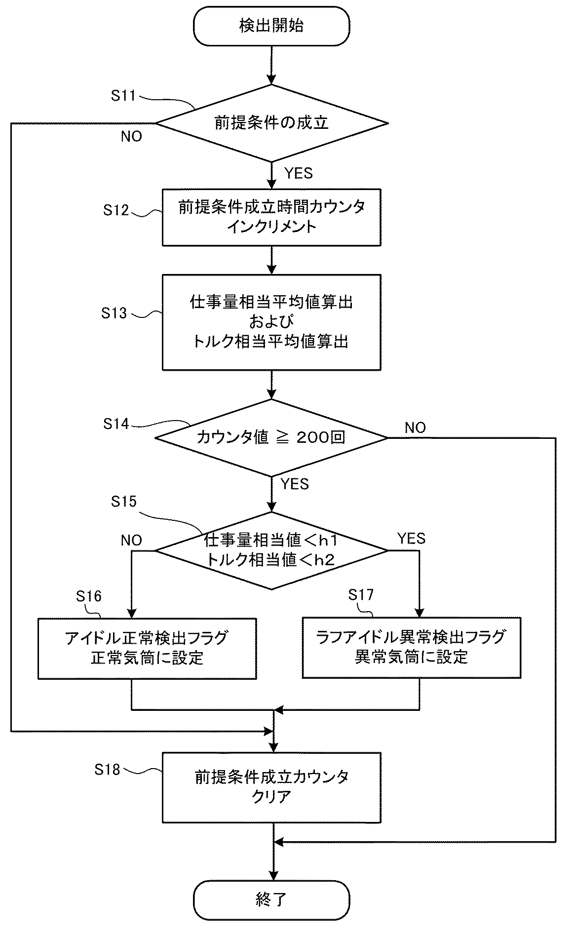
図3は、本実施形態の内燃機関のラフアイドル検出装置において実行される検出処理のフローチャートであり、エンジン1の運転時に、ECU30では、図3に示すような処理が予め設定された算出周期で繰り返し実行される。
FIG. 3 is a flowchart of the detection process executed in the rough idle detection device for the internal combustion engine of the present embodiment. During operation of the
まず、条件判定部31により、上述したラフアイドル異常検出処理の前提条件が成立するか否かが判定される(ステップS11)。
First, the
このとき、ラフアイドル異常検出処理の前提条件が成立すると判定されれば、エンジン1は、アイドル安定状態で負荷変動なく運転されていることになる。
At this time, if it is determined that the precondition for the rough idle abnormality detection process is satisfied, the
このラフアイドル異常検出処理の前提条件が成立すると(ステップS11でYESの場合)、前提条件成立時間カウンタ35がインクリメントされた後(ステップS12)、仕事量相当値算出部32でエンジン1の複数の気筒2内での燃焼によるクランク軸5の回転速度Neの変動成分が、気筒2毎に抽出されるとともに各気筒2の燃焼周期毎の一定回転区間(180°CA)で積分されて仕事量相当値Sneflt#1〜Sneflt#4が算出され、それら今回の算出値が仕事量相当値efic_eficout[#k(i)]として平均値算出部34に取り込まれ、前回の平均化処理後の算出値として平均値算出部34に記憶されている値einstab_eficoutav[#k(i−1)]との平均値が算出され、その算出結果が、今回の平均化処理後の仕事量相当平均値einstab_eficoutav[#k(i)]として記憶される(ステップS13)。
When the precondition for the rough idle abnormality detection process is satisfied (in the case of YES at step S11), after the precondition
また、これと併せて、トルク相当値算出部33により、各気筒2の燃焼周期毎であって仕事量相当値算出部32とは異なるクランク回転位相で回転速度Neが取り込まれ、各気筒2の膨張行程の開始時期における相対的に低速な低速回転領域Raと、各気筒2の膨張行程でクランク軸5の回転速度が最大速度域に達する高速回転領域Rbとにおける回転速度Neの2乗の差(Nea2−Neb2)から各気筒2の発生トルク相当のトルク相当値ΔNe2[#1]〜ΔNe2[#4]が算出され、それら今回の算出値が平均値算出部34に今回のトルク相当値edom2_edom2[#k(i)]として取り込まれ、前回の平均化処理後の算出値としてメモリに記憶されている値einstab_edom2av[#k(i−1)]との平均値を算出した結果が、今回の平均化処理後のトルク相当平均値einstab_edom2av[#k(i)]としてメモリに格納される(ステップS13)。
At the same time, the torque equivalent
次いで、前提条件成立時間カウンタ35のカウント値が200回に達したか否かが判定され(ステップS14)、達していなければ(ステップS14でNOの場合)、今回の処理が終了する。
Next, it is determined whether or not the count value of the precondition
この場合、ラフアイドル異常検出処理の前提条件が次に成立すると、再度上述の一連の算出および平均化処理が繰り返されることになる。 In this case, when the precondition for the rough idle abnormality detection process is satisfied next, the above-described series of calculation and averaging processes are repeated again.
すなわち、前提条件成立時間カウンタ35のカウント値が200回に達するまで、仕事量相当値算出部32では、仕事量相当値efic_eficout[#k(i)]が繰り返し算出されるとともに、その仕事量相当値の算出値efic_eficout[#k(1)]〜efic_eficout[#k(200)]までの順次の平均値算出によりなまし処理した仕事量相当平均値einstab_eficoutav[#k(i)]が算出され、一方、トルク相当値算出部33では、各気筒2についてのトルク相当値edom2_edom2[#k(i)]が繰り返し算出されるとともに、各気筒2についてのトルク相当値の算出値edom2_edom2[#k(1)]〜edom2_edom2[#k(200)]までの順次の平均値算出によりなまし処理したトルク相当平均値einstab_edom2av[#k(i)]が算出されることになる。
That is, until the count value of the precondition
一方、前提条件成立時間カウンタ35のカウント値が200回に達すると(ステップS14でYESの場合)、平均値算出部34からの出力に基づき、異常気筒検出部36により、気筒2毎の仕事量相当平均値einstab_eficoutav[#k(i)]およびトルク相当平均値einstab_edom2av[#k(i)]が、それぞれに対応する判定閾値h1、h2と比較される(ステップS15)。
On the other hand, when the count value of the precondition
このとき、仕事量相当平均値einstab_eficoutav[#k(i)]およびトルク相当平均値einstab_edom2av[#k(i)]がそれぞれに対応する判定閾値h1、h2以上の値となれば(ステップS15でNOの場合)、アイドル運転状態が正常であることを示すアイドル正常フラグeinstab_exproughが設定される(ステップS16)。 At this time, if the work-equivalent average value einstab_eficoutav [#k (i)] and the torque-equivalent average value einstab_edom2av [#k (i)] are equal to or higher than the corresponding determination threshold values h1, h2 (NO in step S15). In this case, the idle normal flag einstab_exprough indicating that the idle operation state is normal is set (step S16).
逆に、仕事量相当平均値einstab_eficoutav[#k(i)]およびトルク相当平均値einstab_edom2av[#k(i)]がそれぞれに対応する判定閾値h1、h2未満の値となれば(ステップS15でYESの場合)、ラフアイドル異常気筒が検出されたことを示すラフアイドル異常検出フラグeinstab_exdroughおよびラフアイドル異常気筒の気筒番号を示すラフアイドル異常気筒フラグeinstab_exdclがそれぞれ設定される(ステップS17)。 On the contrary, if the work equivalent average value einstab_eficoutav [#k (i)] and the torque equivalent average value einstab_edom2av [#k (i)] are values corresponding to the respective determination threshold values h1 and h2 (YES in step S15) ), A rough idle abnormality detection flag einstab_exdrow indicating that a rough idle abnormal cylinder has been detected, and a rough idle abnormal cylinder flag einstab_exdcl indicating the cylinder number of the rough idle abnormal cylinder are set (step S17).
次いで、前提条件成立時間カウンタ35のカウント値がクリアされ(ステップS18)、今回の処理が終了する。
Next, the count value of the precondition
そして、次回の検出処理に際して、条件判定部31によりラフアイドル異常検出処理の前提条件が成立すると判定されれば(ステップS11でYESの場合)、上述の一連の処理(ステップS12〜S18)が再度実行され、条件判定部31によりラフアイドル異常検出処理の前提条件が成立すると判定されなければ(ステップS11でNOの場合)、そのまま前提条件成立時間カウンタ35のカウント値がクリアされて(ステップS18)、次回の処理が終了する。
In the next detection process, if the
このように、本実施形態においては、エンジン1のクランク軸5の実回転数を計測して異なる算出方法で求めた仕事量相当平均値einstab_eficoutav[#k(i)]およびトルク相当平均値einstab_edom2av[#k(i)]を基に、各気筒2の燃焼周期相当の一定角度周期(180°CA)毎の仕事量の変化および各気筒2の燃焼毎の発生トルクの変化を検出するようにしているので、インジェクタ18からの実燃料噴射量が不足・変動し、ECU30で設定される目標回転数に対して実回転数が変動し不快な振動を伴うラフアイドル状態となっているか否かを的確に判定することができる高診断精度のラフアイドル検出装置となる。しかも、仕事量相当値やトルク相当値がそのエンジン1の他の制御のために算出される場合には、ECU30における計算負荷を増大させることなく高精度のラフアイドル検出を行なうことができる。
Thus, in this embodiment, the work equivalent average value einstab_eficoutav [#k (i)] and the torque equivalent average value einstab_edom2av [] obtained by measuring the actual rotational speed of the
また、本実施形態においては、ラフアイドル検出条件が一定時間(例えば前提条件成立時間カウンタ値が200回に達する時間)以上成立する場合に、その間で平均化処理した仕事量相当平均値einstab_eficoutav[#k(i)]およびトルク相当平均値einstab_edom2av[#k(i)]を基にラフアイドル検出を行なうので、エンジン1のラフアイドル状態における各気筒2の燃焼毎の実回転変動とラフアイドル振動を生じる要因となる気筒2とを精度よく検出することができる。
In the present embodiment, when the rough idle detection condition is satisfied for a certain time (for example, the time when the precondition satisfying time counter value reaches 200 times) or more, the work equivalent average value einstab_eficoutav [# k (i)] and the torque equivalent average value einstab_edom2av [#k (i)], the rough idle detection is performed, so that the actual rotation fluctuation and the rough idle vibration for each combustion of each
さらに、ラフアイドル異常気筒が検出されたことを示すラフアイドル異常検出フラグeinstab_exdroughの設定に加えて、仕事量相当平均値einstab_eficoutav[#k(i)]およびトルク相当平均値einstab_edom2av[#k(i)]がそれぞれに対応する判定閾値h1、h2を下回る気筒2について、ラフアイドル状態を引き起こす可能性の高い気筒としてラフアイドル異常気筒フラグeinstab_exdclが設定され、外部の診断装置100による診断時に読み取り可能な形態で記憶・保持されるので、ラフアイドル振動に対するディーラー等での検査やメンテナンスの際に、ラフアイドル異常検出フラグeinstab_exdroughおよびラフアイドル異常気筒フラグeinstab_exdclを参照することで、ラフアイドル状態の発生およびその要因を迅速かつ確実に把握することができ、サービス性を向上させることができる。
Further, in addition to the setting of the rough idle abnormality detection flag einstab_exrough indicating that the rough idle abnormal cylinder has been detected, the work equivalent average value einstab_eficoutav [#k (i)] and the torque equivalent average value einstab_edom2av [#k (i) ] Is set to a rough idle abnormal cylinder flag einstab_excl as a cylinder that is highly likely to cause a rough idle state for
加えて、本実施形態では、ラフアイドル異常検出処理を実行するための前提条件が成立したときにのみ、上述した検出処理が実行されるので、ラフアイドル状態の検出処理を担うECU30内のCPUの処理能力を通常運転時には必要な他の算出処理に割り当てることができ、計算用資源を有効活用できる。
In addition, in the present embodiment, since the detection process described above is executed only when the precondition for executing the rough idle abnormality detection process is satisfied, the CPU in the
また、ラフアイドル異常検出を行なうための前提条件が、エンジン1の気筒2毎に設けられたインジェクタ18の噴射特性を学習する学習処理(例えば、アイドル回転数制御下における各インジェクタ18の燃料噴射量のばらつきの学習処理)の実行条件が満足されていること、アクセル開度が最小値(0%)であること、エンジン1を動力源とする車両の車速がゼロ[km/h]であること、エンジン1の冷間始動時のアイドル回転数が暖機完了時のアイドル回転数より高回転数に設定されるアイドルアップ制御が実行されていないことといった条件を含むので、外乱要因を抑えたほぼ一定条件下で、アイドル回転数の変動を精度良く検出できる。
Further, the precondition for detecting rough idle abnormality is a learning process for learning the injection characteristics of the
併せて、前提条件は、エンジン1の補機負荷(エアコン等)が切り替えられていないことおよび変速機がニュートラル状態であることのうち少なくとも一方の条件を含み、コモンレール式の多気筒のディーゼル機関であるエンジン1のインジェクタ18により実行される燃料噴射条件(燃焼モード)の切り替えが禁止されていることを前提条件に更に含むので、外乱要因を更に抑えたほぼ一定条件下で、アイドル回転数の変動を精度良く算出できる。
In addition, the precondition includes at least one of the conditions that the auxiliary load (such as an air conditioner) of the
また、エンジン1の気筒数に対応する一定の周期であって互いに異なる回転位相でクランク軸5の実回転数を計測して、それぞれの算出に最適なタイミングで精度良く算出した仕事量相当平均値einstab_eficoutav[#k(i)]およびトルク相当平均値einstab_edom2av[#k(i)]を基にラフアイドル検出およびラフアイドル異常気筒検出を行なうので、ECU30のCPU(計算用の資源)の処理負荷の集中を回避できる。
In addition, the actual rotation number of the
さらに、異常気筒検出部36が、第1の判定モードと第2の判定モードとに切り替え可能であるので、エンジン1のECU30が仕事量相当値およびトルク相当値を共に算出する制御仕様であっても、仕事量相当値およびトルク相当値のうちいずれか片方のみを算出する制御仕様であっても、それぞれに対応可能となり、各種仕様のエンジンに対応可能なラフアイドル検出装置にできる。
Further, since the abnormal
なお、上述の実施形態においては、気筒2毎の仕事量相当平均値einstab_eficoutav[#k(i)]およびトルク相当平均値einstab_edom2av[#k(i)]の双方がそれぞれに対応する判定閾値h1、h2を共に下回る気筒2について、その気筒2内での燃焼がラフアイドル状態の要因になることを示す異常検出フラグを設定するものとしたが、気筒2毎の仕事量相当平均値einstab_eficoutav[#k(i)]およびトルク相当平均値einstab_edom2av[#k(i)]のうち少なくとも1つがそれに対応する判定閾値h1またはh2を下回る気筒2について、その気筒2内での燃焼がラフアイドル状態の要因になることを示すフラグを設定することもできるし、双方が共に判定閾値h1、h2を下回るかいずれか一方のみが判定閾値h1、h2のいずれかを下回るかによって、異常気筒であるか異常気筒候補であるかといった程度に診断レベルの異なる複数種のラフアイドル異常検出フラグを設定することもできる。
In the above-described embodiment, the determination threshold value h1 corresponding to both the work equivalent average value einstab_eficoutav [#k (i)] and the torque equivalent average value einstab_edom2av [#k (i)] for each
また、上述の実施形態においては、仕事量相当値とトルク相当値の算出のための回転計測期間を燃焼周期毎であって位相の異なる期間としたが、仕事量相当値の算出のための回転計測期間内に低速回転角度領域Raおよび高速度回転領域Rbを設定することで、トルク相当値の算出のための回転計測期間を仕事量相当値の算出のための回転計測期間と同一の位相とすることもできる。 In the above-described embodiment, the rotation measurement period for calculating the work equivalent value and the torque equivalent value is set to a period having a different phase for each combustion cycle. By setting the low-speed rotation angle region Ra and the high-speed rotation region Rb within the measurement period, the rotation measurement period for calculating the torque equivalent value is set to the same phase as the rotation measurement period for calculating the work equivalent value. You can also
以上説明したように、本発明に係る内燃機関のラフアイドル検出装置は、ラフアイドル状態における実回転変動を仕事量相当値およびトルク相当値の双方を基に的確に把握することができ、ラフアイドル状態か否かを的確に判定することができる高診断精度の内燃機関のラフアイドル検出装置を提供することができるという効果を奏するものであり、燃料噴射量の不足等により内燃機関のアイドル運転時のエンジン回転数が目標回転数に対し不安定に変動するラフアイドル状態を検出する内燃機関のラフアイドル検出装置全般に有用である。 As described above, the rough idle detecting device for an internal combustion engine according to the present invention can accurately grasp the actual rotational fluctuation in the rough idle state based on both the work equivalent value and the torque equivalent value. It is possible to provide a rough idle detection device for an internal combustion engine with high diagnostic accuracy that can accurately determine whether or not the engine is in a state. This is useful for general rough idle detection devices for internal combustion engines that detect a rough idle state in which the engine rotational speed of the engine fluctuates in an unstable manner with respect to the target rotational speed.
1 エンジン(内燃機関)
2 気筒
3 燃焼室
5 クランク軸
11 燃料タンク
12 フィードポンプ
13 調量弁
15 加圧ポンプ
15a カムシャフト
17 コモンレール
18 インジェクタ
18a 電磁弁部
18b 燃料噴射部
19 高圧配管
20 EDU
21 アクセル開度センサ
22 燃料圧力センサ
23 クランク角センサ(回転数検出手段)
24 車速センサ
25 水温センサ
26 ニュートラルスイッチ
27 エアコンスイッチ
30 ECU(電子制御ユニット、回転数検出手段)
31 条件判定部(前提条件判定手段)
32 仕事量相当値算出部(仕事量相当値算出手段)
33 トルク相当値算出部(トルク相当値算出手段)
34 平均値算出部(仕事量相当値算出手段、トルク相当値算出手段)
35 前提条件成立時間カウンタ
36 異常気筒検出部(異常気筒判定手段)
100 診断装置
h1、h2 判定閾値
1 engine (internal combustion engine)
2
21
24
31 Condition determining unit (precondition determining means)
32 Work equivalent value calculation unit (work equivalent value calculation means)
33 Torque equivalent value calculation unit (torque equivalent value calculation means)
34 Average value calculation unit (work equivalent value calculation means, torque equivalent value calculation means)
35 Precondition
100 diagnostic device h1, h2 judgment threshold
Claims (9)
前記内燃機関のクランク軸の回転速度を検出する回転速度検出手段と、
前記回転速度検出手段の検出情報に基づいて前記内燃機関の気筒内での燃焼による前記クランク軸の回転速度の変動成分を抽出するとともに、該抽出した変動成分を積分した仕事量相当値を算出する仕事量相当値算出手段と、
前記気筒の膨張行程の開始時期における相対的に低速な低速回転領域と、前記気筒の膨張行程で前記クランク軸の回転速度が最大速度域に達する高速回転領域とにおける前記クランク軸の回転速度の2乗の差から前記気筒での発生トルク相当のトルク相当値を算出するトルク相当値算出手段と、
前記仕事量相当値および前記トルク相当値をそれぞれに対応する判定閾値と比較して、前記仕事量相当値および前記トルク相当値が前記それぞれに対応する判定閾値を下回るとき前記気筒内での燃焼が前記ラフアイドル状態の要因になると判定する異常気筒判定手段と、を備えたことを特徴とする内燃機関のラフアイドル検出装置。 A rough idle detection device for an internal combustion engine for detecting a rough idle state in which the rotational speed of the crankshaft fluctuates with respect to the target rotational speed under an idle operation state in which the rotational speed of the crankshaft of the internal combustion engine is controlled to a target rotational speed. There,
Rotational speed detection means for detecting the rotational speed of the crankshaft of the internal combustion engine;
Based on the detection information of the rotation speed detection means, a fluctuation component of the rotation speed of the crankshaft due to combustion in the cylinder of the internal combustion engine is extracted, and a work equivalent value obtained by integrating the extracted fluctuation component is calculated. A work equivalent value calculating means;
2 of the rotational speed of the crankshaft in the relatively slow low speed rotation region at the start timing of the expansion stroke of the cylinder and the high speed rotation region in which the rotational speed of the crankshaft reaches the maximum speed region in the expansion stroke of the cylinder. Torque equivalent value calculating means for calculating a torque equivalent value corresponding to the torque generated in the cylinder from the difference in power;
Comparing the work equivalent value and the torque equivalent value with the corresponding determination threshold values, and when the work equivalent value and the torque equivalent value are lower than the corresponding determination threshold values, combustion in the cylinder is performed. A rough idle detecting device for an internal combustion engine, comprising: an abnormal cylinder determining unit that determines that the rough idle state is caused.
前記トルク相当値算出手段が、各気筒の燃焼周期毎に、各気筒の膨張行程の開始時期における相対的に低速な低速回転領域と、前記各気筒の膨張行程で前記クランク軸の回転速度が最大速度域に達する高速回転領域とにおける前記クランク軸の回転速度の2乗の差から各気筒での発生トルク相当のトルク相当値を前記繰り返し回数だけ繰り返し算出するとともに、該各気筒についてのトルク相当値の算出値を平均化処理したトルク相当値を算出することを特徴とする請求項1に記載の内燃機関のラフアイドル検出装置。 The work equivalent value calculating means extracts a fluctuation component of the rotation speed of the crankshaft due to combustion in a plurality of cylinders of the internal combustion engine for each cylinder, and integrates it in a constant rotation interval for each combustion cycle of each cylinder. A work equivalent value for each cylinder is repeatedly calculated for a preset number of repetitions, and a work equivalent value obtained by averaging the calculated values of the work equivalent values is calculated.
The torque equivalent value calculating means has a relatively slow low-speed rotation region at the start of the expansion stroke of each cylinder and a maximum rotation speed of the crankshaft in the expansion stroke of each cylinder for each combustion cycle of each cylinder. A torque equivalent value corresponding to the torque generated in each cylinder is repeatedly calculated by the number of repetitions from the difference between the squares of the rotation speed of the crankshaft in the high-speed rotation region reaching the speed range, and the torque equivalent value for each cylinder 2. The rough idle detection device for an internal combustion engine according to claim 1, wherein a torque equivalent value obtained by averaging the calculated values is calculated.
前記前提条件が成立するとき、前記仕事量相当値算出手段および前記異常気筒判定手段が、それぞれの処理を実行することを特徴とする請求項1ないし請求項3のうちいずれか1の請求項に記載の内燃機関のラフアイドル検出装置。 Precondition determining means for determining whether or not a precondition set in advance as a condition for executing the processing for detecting the rough idle state of the internal combustion engine is satisfied;
The claim according to any one of claims 1 to 3, wherein when the precondition is satisfied, the work equivalent value calculation means and the abnormal cylinder determination means execute respective processes. A rough idle detection device for an internal combustion engine as described.
前記前提条件は、前記ディーゼル機関の前記燃料噴射弁により実行される燃料噴射条件の切り替えが禁止されていること、を含むことを特徴とする請求項4に記載の内燃機関のラフアイドル検出装置。 The internal combustion engine is a common rail multi-cylinder diesel engine;
5. The rough idle detection device for an internal combustion engine according to claim 4, wherein the precondition includes prohibition of switching of a fuel injection condition executed by the fuel injection valve of the diesel engine.
Priority Applications (2)
| Application Number | Priority Date | Filing Date | Title |
|---|---|---|---|
| JP2008319866A JP2010144533A (en) | 2008-12-16 | 2008-12-16 | Rough idle detecting device of internal combustion engine |
| PCT/IB2009/007921 WO2010070446A1 (en) | 2008-12-16 | 2009-12-08 | Rough idle detecting apparatus and rough idle detecting method for internal combustion engine |
Applications Claiming Priority (1)
| Application Number | Priority Date | Filing Date | Title |
|---|---|---|---|
| JP2008319866A JP2010144533A (en) | 2008-12-16 | 2008-12-16 | Rough idle detecting device of internal combustion engine |
Publications (1)
| Publication Number | Publication Date |
|---|---|
| JP2010144533A true JP2010144533A (en) | 2010-07-01 |
Family
ID=41786034
Family Applications (1)
| Application Number | Title | Priority Date | Filing Date |
|---|---|---|---|
| JP2008319866A Pending JP2010144533A (en) | 2008-12-16 | 2008-12-16 | Rough idle detecting device of internal combustion engine |
Country Status (2)
| Country | Link |
|---|---|
| JP (1) | JP2010144533A (en) |
| WO (1) | WO2010070446A1 (en) |
Cited By (10)
| Publication number | Priority date | Publication date | Assignee | Title |
|---|---|---|---|---|
| JP2012193707A (en) * | 2011-03-17 | 2012-10-11 | Bosch Corp | Fuel injection amount correcting method for common rail type fuel injection control device, and the common rail type fuel injection control device |
| JP2013238122A (en) * | 2012-05-11 | 2013-11-28 | Toyota Motor Corp | Failure diagnosis device of internal combustion engine, and control device of internal combustion engine |
| JP2013253562A (en) * | 2012-06-07 | 2013-12-19 | Toyota Motor Corp | Rough idle detection device for internal combustion engine |
| US9567933B2 (en) | 2012-09-24 | 2017-02-14 | Mazda Motor Corporation | Controller and control method for engines |
| JP2019065820A (en) * | 2017-10-05 | 2019-04-25 | トヨタ自動車株式会社 | Internal combustion engine control device |
| KR102119865B1 (en) * | 2019-04-02 | 2020-06-05 | 현대오트론 주식회사 | Misfire diagnosis method and device of single cylinder four-stroke engine |
| KR102119852B1 (en) * | 2019-04-02 | 2020-06-05 | 현대오트론 주식회사 | Misfire diagnosis method and device of single cylinder four-stroke engine |
| KR102131713B1 (en) * | 2019-07-25 | 2020-07-08 | 현대오트론 주식회사 | Misfire diagnosis method and device of Multi cylinder four-stroke engine |
| KR102153484B1 (en) * | 2019-07-25 | 2020-09-08 | 현대오트론 주식회사 | Misfire diagnosis method and device of Multi cylinder four-stroke engine |
| JP7635660B2 (en) | 2021-07-08 | 2025-02-26 | トヨタ自動車株式会社 | Device for determining injection abnormality in an internal combustion engine |
Families Citing this family (1)
| Publication number | Priority date | Publication date | Assignee | Title |
|---|---|---|---|---|
| SE537390C2 (en) * | 2012-10-24 | 2015-04-21 | Scania Cv Ab | Combustion engine diagnosis |
Family Cites Families (6)
| Publication number | Priority date | Publication date | Assignee | Title |
|---|---|---|---|---|
| US4697561A (en) * | 1985-04-15 | 1987-10-06 | Purdue Research Foundation | On-line engine torque and torque fluctuation measurement for engine control utilizing crankshaft speed fluctuations |
| JP3262003B2 (en) * | 1996-12-17 | 2002-03-04 | トヨタ自動車株式会社 | Output fluctuation detection method for multi-cylinder internal combustion engine |
| JP2007192081A (en) | 2006-01-18 | 2007-08-02 | Toyota Motor Corp | Control device for internal combustion engine |
| JP4706525B2 (en) * | 2006-03-22 | 2011-06-22 | 株式会社デンソー | Fuel injection control device |
| JP4552899B2 (en) | 2006-06-06 | 2010-09-29 | 株式会社デンソー | Fuel injection control device |
| DE602006013475D1 (en) * | 2006-10-23 | 2010-05-20 | Delphi Tech Holding Sarl | Method and device for controlling an internal combustion engine |
-
2008
- 2008-12-16 JP JP2008319866A patent/JP2010144533A/en active Pending
-
2009
- 2009-12-08 WO PCT/IB2009/007921 patent/WO2010070446A1/en not_active Ceased
Cited By (10)
| Publication number | Priority date | Publication date | Assignee | Title |
|---|---|---|---|---|
| JP2012193707A (en) * | 2011-03-17 | 2012-10-11 | Bosch Corp | Fuel injection amount correcting method for common rail type fuel injection control device, and the common rail type fuel injection control device |
| JP2013238122A (en) * | 2012-05-11 | 2013-11-28 | Toyota Motor Corp | Failure diagnosis device of internal combustion engine, and control device of internal combustion engine |
| JP2013253562A (en) * | 2012-06-07 | 2013-12-19 | Toyota Motor Corp | Rough idle detection device for internal combustion engine |
| US9567933B2 (en) | 2012-09-24 | 2017-02-14 | Mazda Motor Corporation | Controller and control method for engines |
| JP2019065820A (en) * | 2017-10-05 | 2019-04-25 | トヨタ自動車株式会社 | Internal combustion engine control device |
| KR102119865B1 (en) * | 2019-04-02 | 2020-06-05 | 현대오트론 주식회사 | Misfire diagnosis method and device of single cylinder four-stroke engine |
| KR102119852B1 (en) * | 2019-04-02 | 2020-06-05 | 현대오트론 주식회사 | Misfire diagnosis method and device of single cylinder four-stroke engine |
| KR102131713B1 (en) * | 2019-07-25 | 2020-07-08 | 현대오트론 주식회사 | Misfire diagnosis method and device of Multi cylinder four-stroke engine |
| KR102153484B1 (en) * | 2019-07-25 | 2020-09-08 | 현대오트론 주식회사 | Misfire diagnosis method and device of Multi cylinder four-stroke engine |
| JP7635660B2 (en) | 2021-07-08 | 2025-02-26 | トヨタ自動車株式会社 | Device for determining injection abnormality in an internal combustion engine |
Also Published As
| Publication number | Publication date |
|---|---|
| WO2010070446A1 (en) | 2010-06-24 |
Similar Documents
| Publication | Publication Date | Title |
|---|---|---|
| JP2010144533A (en) | Rough idle detecting device of internal combustion engine | |
| JP4096924B2 (en) | Injection amount control device for internal combustion engine | |
| US7027911B2 (en) | Apparatus for controlling engine rotation stop by estimating kinetic energy and stop position | |
| US10072628B2 (en) | Control device for internal combustion engine | |
| JP6281581B2 (en) | Control device for internal combustion engine | |
| JP2010275989A (en) | Fuel injection control apparatus for internal combustion engine | |
| JP2006125370A (en) | Injection quantity self-learning controller | |
| JP5086228B2 (en) | Operation control device for internal combustion engine | |
| JP5821566B2 (en) | Abnormality detection apparatus for internal combustion engine | |
| JP2020172889A (en) | Internal combustion engine control device | |
| GB2383646A (en) | Diagnostic method and system for a variable compression ratio internal combustion engine | |
| JP2013177824A (en) | Detection device for continued injection of fuel | |
| JP5522058B2 (en) | Fault diagnosis device for internal combustion engine | |
| JP3695411B2 (en) | Fuel injection control device for internal combustion engine | |
| JP2020172892A (en) | Internal combustion engine control device | |
| JP3876766B2 (en) | Injection rate control device for internal combustion engine | |
| EP2037104B1 (en) | Fuel volatility recognition method during the postcranking step of an internal combustion engine | |
| JP5105023B2 (en) | In-cylinder pressure estimation device for internal combustion engine | |
| JP2004211667A (en) | Control device for internal combustion engine | |
| JP5381747B2 (en) | Fuel injection device | |
| JP2010138754A (en) | Fuel injection control device for internal combustion engine | |
| CN111810334A (en) | Internal combustion engine control system and internal combustion engine | |
| JP4492508B2 (en) | Fuel injection control device | |
| JP2011231679A (en) | Control device for internal combustion engine | |
| JP2003184608A (en) | Fuel injection control device for multi-cylinder internal combustion engine |