JP2010143485A - Wheel position specifying system - Google Patents

Wheel position specifying system Download PDF

Info

Publication number
JP2010143485A
JP2010143485A JP2008324570A JP2008324570A JP2010143485A JP 2010143485 A JP2010143485 A JP 2010143485A JP 2008324570 A JP2008324570 A JP 2008324570A JP 2008324570 A JP2008324570 A JP 2008324570A JP 2010143485 A JP2010143485 A JP 2010143485A
Authority
JP
Japan
Prior art keywords
wheel
position specifying
vehicle
wheel position
transmitter
Prior art date
Legal status (The legal status is an assumption and is not a legal conclusion. Google has not performed a legal analysis and makes no representation as to the accuracy of the status listed.)
Pending
Application number
JP2008324570A
Other languages
Japanese (ja)
Inventor
澄靖 ▲高▼森
Suminobu Takamori
Current Assignee (The listed assignees may be inaccurate. Google has not performed a legal analysis and makes no representation or warranty as to the accuracy of the list.)
Toyota Motor Corp
Original Assignee
Toyota Motor Corp
Priority date (The priority date is an assumption and is not a legal conclusion. Google has not performed a legal analysis and makes no representation as to the accuracy of the date listed.)
Filing date
Publication date
Application filed by Toyota Motor Corp filed Critical Toyota Motor Corp
Priority to JP2008324570A priority Critical patent/JP2010143485A/en
Publication of JP2010143485A publication Critical patent/JP2010143485A/en
Pending legal-status Critical Current

Links

Images

Abstract

<P>PROBLEM TO BE SOLVED: To avoid the event that a receiving device cannot receive electric waves from a transmitting device depending on the rotating angle of a wheel to an axle. <P>SOLUTION: This wheel position specifying system 200 executes wheel position specifying processing. Herein, a transceiver 16 is provided on each wheel 14 for transmitting identifying information for the wheel 14. A receiver 20 is provided on a vehicle body 12 on which each wheel 14 is mounted, for receiving the identifying information. A wheel position specifying means specifies the position of the wheel 14 on which the transceiver 16 transmitting the identifying information is provided, in accordance with the identifying information. A control means controls the wheel position specifying processing and determines whether the wheel position specifying means specifies the position of each wheel 14 or not. A vehicle travel detecting means detects the travel of the vehicle 10. When determining that the wheel position specifying means does not specify the position of each wheel 14 at stopping the vehicle, the control means executes the wheel position specifying processing again after the vehicle travel detecting means detects the travel of the vehicle 10. <P>COPYRIGHT: (C)2010,JPO&INPIT

Description

本発明は、車輪位置特定システムに関する。   The present invention relates to a wheel position specifying system.

近年、より安全な車両の走行を実現するために、タイヤの空気圧や温度などの情報を無線で車体側に送信してドライバーに知らせるタイヤ空気圧監視システム(TPMS:Tire Pressure Monitoring System)の開発が進められている。タイヤ空気圧監視システムでは、タイヤ空気圧などの車輪情報を検出する車輪情報検出ユニットが各車輪に設けられる。車体に設けられる受信側の制御ユニットは、車輪情報検出ユニットがどの位置の車輪に設けられているか特定したうえで、車輪情報検出ユニットから車輪情報を受けとる。   In recent years, in order to realize safer vehicle driving, tire pressure monitoring system (TPMS: Tire Pressure Monitoring System) has been developed to notify the driver by wirelessly transmitting information such as tire pressure and temperature to the vehicle body. It has been. In the tire pressure monitoring system, each wheel is provided with a wheel information detection unit that detects wheel information such as tire pressure. The control unit on the reception side provided in the vehicle body receives wheel information from the wheel information detection unit after specifying the position of the wheel information detection unit on which wheel.

特許文献1には、車体に搭載される受信装置が受信する信号の送信源である送信装置を特定する車両情報処理装置が開示されている。
特開2006−107253号公報
Patent Document 1 discloses a vehicle information processing device that identifies a transmission device that is a transmission source of a signal received by a reception device mounted on a vehicle body.
JP 2006-107253 A

ところで特許文献1に開示された技術において、送信装置は各車輪に搭載される。このとき、車輪の車軸に対する回転角によっては、受信装置が送信装置の電波を受信できない場合がある。受信装置と送信装置との通信が不能な状態にあれば、車両情報処理装置は、各車輪の位置を特定することができない。また、車両情報処理装置が各車輪の位置を特定するまで車輪位置特定処理を繰り返し実行すれば、受信装置が送信装置の電波が受信できないにもかかわらず、送信装置は電波を送信し続けることになり、無用な電力が消費されることになる。   By the way, in the technique disclosed in Patent Document 1, the transmission device is mounted on each wheel. At this time, depending on the rotation angle of the wheel with respect to the axle, the receiving device may not be able to receive radio waves from the transmitting device. If the communication between the receiving device and the transmitting device is impossible, the vehicle information processing device cannot specify the position of each wheel. Further, if the vehicle information processing apparatus repeatedly executes the wheel position specifying process until the position of each wheel is specified, the transmitting apparatus continues to transmit radio waves even though the receiving apparatus cannot receive radio waves from the transmitting apparatus. Thus, useless power is consumed.

本発明はこうした状況に鑑みてなされたものであり、その目的は、無用な電力消費を抑えつつ、車両に設けられる複数の車輪のうち送信機がどの車輪に設けられているかを特定する技術を提供することにある。   The present invention has been made in view of such a situation, and an object of the present invention is to identify a wheel on which a transmitter is provided among a plurality of wheels provided on a vehicle while suppressing unnecessary power consumption. It is to provide.

上記課題を解決するために、本発明のある態様の車輪位置特定システムは、車輪位置特定処理を実行する車輪位置特定システムであって、各車輪に設けられ、車輪の識別情報を送信する送信機と、各車輪が装着された車両本体に設けられ、識別情報を受信する受信機と、識別情報にもとづいて、識別情報を送信した送信機が設けられている車輪の位置を特定する車輪位置特定手段と、車輪位置特定処理を制御し、車輪位置特定手段が各車輪の位置を特定したかどうかを判定する制御手段と、車両の走行を検出する車両走行検出手段と、を備える。制御手段は、車両停止時に車輪位置特定手段が各車輪の位置を特定していないと判定する場合に、車両走行検出手段が車両の走行を検出したのちに、車輪位置特定処理を再実行する。この態様によると、車両停止時に車輪の位置を特定できない場合であっても、車両が動いて車輪の回転角が変化したのちに各車輪の位置を特定する処理を再実行することができる。   In order to solve the above-described problems, a wheel position specifying system according to an aspect of the present invention is a wheel position specifying system that executes a wheel position specifying process, and is a transmitter that is provided in each wheel and transmits wheel identification information. And a wheel position specification that specifies a position of a wheel provided in a vehicle main body to which each wheel is mounted and that receives identification information and a transmitter that transmits identification information based on the identification information. Means, control means for controlling the wheel position specifying process, and determining whether the wheel position specifying means specified the position of each wheel, and vehicle running detecting means for detecting the running of the vehicle. When it is determined that the wheel position specifying means does not specify the position of each wheel when the vehicle is stopped, the control means re-executes the wheel position specifying process after the vehicle running detection means detects the vehicle running. According to this aspect, even when the wheel position cannot be specified when the vehicle is stopped, the process of specifying the position of each wheel can be re-executed after the vehicle moves and the wheel rotation angle changes.

制御手段は、車輪位置特定処理を所定回数実行して、各車輪の位置を特定できなければ、車輪位置特定処理を停止してもよい。これにより、車輪位置特定システムにおいて車輪位置特定処理にかかる電力消費を抑えることができる。   The control means may execute the wheel position specifying process a predetermined number of times, and stop the wheel position specifying process if the position of each wheel cannot be specified. Thereby, the power consumption concerning a wheel position specific process in a wheel position specific system can be suppressed.

送信機は、車輪位置特定処理における送信処理とは別に、車輪に設けられたセンサにより検出された車輪状態情報を所定周期で受信機に送信し、制御手段は、車輪位置特定手段が各車輪の位置を特定していない場合に、受信機が車輪状態情報を受信していれば、車輪位置特定処理を再実行してもよい。これにより、通信状況が良好なときに車輪位置特定処理を再実行することができ、車輪位置特定処理を完了させる可能性を高めることができる。   The transmitter transmits the wheel state information detected by the sensor provided on the wheel to the receiver at a predetermined cycle separately from the transmission process in the wheel position specifying process, and the control means includes the wheel position specifying means for each wheel. If the position is not specified and the receiver receives wheel state information, the wheel position specifying process may be re-executed. Thus, the wheel position specifying process can be re-executed when the communication status is good, and the possibility of completing the wheel position specifying process can be increased.

車輪位置特定手段は、各車輪に設けられる加速度センサの出力にもとづいて走行輪とスペアタイヤとを区別してもよい。制御手段は、スペアタイヤを備える車両において、スペアタイヤを特定するまで、車輪位置特定処理を実行しない。これにより、車輪位置特定処理にかかる電力消費をより抑えることができる。   The wheel position specifying means may distinguish the traveling wheel from the spare tire based on an output of an acceleration sensor provided on each wheel. The control means does not execute the wheel position specifying process until the spare tire is specified in the vehicle including the spare tire. Thereby, the power consumption concerning a wheel position specific process can be suppressed more.

本発明によれば、無用な電力消費を抑えつつ、車両に設けられる複数の車輪のうち送信機がどの車輪に設けられているかを特定する技術を提供することができる。   ADVANTAGE OF THE INVENTION According to this invention, the technique which specifies to which wheel the transmitter is provided among several wheels provided in a vehicle can be provided, suppressing unnecessary power consumption.

実施形態の車両には、タイヤ空気圧やタイヤ気室内温度などの車輪状態を検出する車輪状態検出装置が備えられる。車輪状態検出装置においては、車輪に設けられた送信機が、車輪識別情報と車輪用センサ類が検出した車輪状態情報とを、車両本体に設けられた受信機に所定の通信周期で送信する。この通信周期は、たとえば、1分である。電子制御ユニット(以下、「ECU」という)は、受信された車輪状態情報にもとづいて車輪の空気圧や温度等に異常があるかどうかを検出する。ECUは、車輪の異常を検出すれば、警報装置により運転者にその異常を伝達する。なお、この前提として、ECUは、送信機が送信する車輪識別情報と車輪の位置との対応関係を特定できていなければ、どの車輪に異常が生じたか特定できない。そこで、ECUは、車輪状態の検出処理を行う前提として車輪の位置をあらかじめ特定しておく必要がある。   The vehicle of the embodiment includes a wheel state detection device that detects wheel states such as tire air pressure and tire air temperature. In the wheel state detection device, a transmitter provided on a wheel transmits wheel identification information and wheel state information detected by wheel sensors to a receiver provided on the vehicle body at a predetermined communication cycle. This communication cycle is, for example, 1 minute. An electronic control unit (hereinafter referred to as “ECU”) detects whether there is an abnormality in the air pressure or temperature of the wheel based on the received wheel state information. If the ECU detects an abnormality in the wheel, the alarm is transmitted to the driver by an alarm device. As a premise, the ECU cannot identify which wheel has an abnormality unless the correspondence between the wheel identification information transmitted by the transmitter and the position of the wheel can be identified. Therefore, the ECU needs to specify the position of the wheel in advance as a premise for performing the wheel state detection process.

実施形態に係る車輪位置特定システムは、無用な電力消費を抑えつつ、各車輪の位置を特定しようとするものである。具体的に車輪位置特定システムは、まず、エンジン始動時で車両の走行開始前に、車輪識別情報を送信した送信機が設けられている車輪の位置を特定する車輪位置特定処理を実行する。車両の走行開始前に各車輪の位置を特定することができれば、車両走行中の車輪状態を適切に検出することができ、望ましい。しかしながら、車両停車時の車輪の回転角によっては、送信機と受信機が通信できず、車輪位置特定処理を完了できないことがある。なお、車輪の回転角とは、車両本体に装着された車輪の車軸に対する回転角をいう。送信機と受信機が通信できないにもかかわらず、送信機が車輪識別情報を送信し続ければ、送信機の無用な電力消費が発生する。そこで、実施形態に係る車輪位置特定システムは、車両の停車時に各車輪の位置を特定することができなければ、車輪位置特定処理を一時中断し、車両の走行を検出したことを契機として、再度、車輪位置特定処理を実行する。これにより、無用な電力消費を抑えつつ、車輪の位置を特定することができる。   The wheel position specifying system according to the embodiment attempts to specify the position of each wheel while suppressing unnecessary power consumption. Specifically, the wheel position specifying system first executes a wheel position specifying process for specifying the position of the wheel provided with the transmitter that transmitted the wheel identification information before the vehicle starts when the engine is started. If the position of each wheel can be specified before the vehicle starts traveling, it is possible to appropriately detect the wheel state during vehicle traveling, which is desirable. However, depending on the rotation angle of the wheel when the vehicle is stopped, the transmitter and the receiver may not be able to communicate and the wheel position specifying process may not be completed. In addition, the rotation angle of a wheel means the rotation angle with respect to the axle of the wheel with which the vehicle main body was mounted | worn. If the transmitter continues to transmit the wheel identification information even though the transmitter and the receiver cannot communicate, unnecessary power consumption of the transmitter occurs. Therefore, if the wheel position specifying system according to the embodiment cannot specify the position of each wheel when the vehicle is stopped, the wheel position specifying process is temporarily interrupted and triggered by the detection of the vehicle traveling again. The wheel position specifying process is executed. Thereby, the position of the wheel can be specified while suppressing unnecessary power consumption.

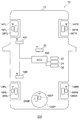
図1は、実施形態に係る車輪位置特定システム200の全体構成図である。車両10は、右前輪14FR、左前輪14FL、右後輪14RR、左後輪14RL、スペア車輪14SP(以下、必要に応じて「車輪14」と総称する)、および車両本体12を有する。   FIG. 1 is an overall configuration diagram of a wheel position specifying system 200 according to the embodiment. The vehicle 10 includes a right front wheel 14FR, a left front wheel 14FL, a right rear wheel 14RR, a left rear wheel 14RL, a spare wheel 14SP (hereinafter collectively referred to as “wheel 14” as necessary), and a vehicle body 12.

右前輪14FR、左前輪14FL、右後輪14RR、および左後輪14RLは車両本体12に装着され、路面に接地して回転することにより車両を走行させる走行輪として機能する。スペア車輪14SPは、これら走行輪のいずれかに異常が生じたときに備えて車両本体12のたとえばトランクルーム下方などに取り付けられている。送受信機16SPと車輪用センサ類28SPを備えるスペア車輪14SPをグランドスペアタイヤという。   The right front wheel 14FR, the left front wheel 14FL, the right rear wheel 14RR, and the left rear wheel 14RL are mounted on the vehicle main body 12 and function as traveling wheels that make the vehicle travel by contacting and rotating on the road surface. The spare wheel 14SP is attached to the vehicle main body 12, for example, below the trunk room, etc. in preparation for an abnormality occurring in any of these traveling wheels. The spare wheel 14SP including the transceiver 16SP and the wheel sensors 28SP is referred to as a ground spare tire.

車輪14はそれぞれタイヤおよびホイールを有する。ホイールの外周部には円筒状に形成されたホイールリムが設けられ、このホイールリムの外周上にタイヤが組み付けられる。こうしてタイヤ内部とホイールリム外周によって囲われる領域にタイヤ気室が形成される。   Each wheel 14 has a tire and a wheel. A wheel rim formed in a cylindrical shape is provided on the outer periphery of the wheel, and a tire is assembled on the outer periphery of the wheel rim. Thus, a tire air chamber is formed in a region surrounded by the inside of the tire and the outer periphery of the wheel rim.

車輪14の各々に対応して、送受信機16FR、送受信機16FL、送受信機16RR、送受信機16RL、および送受信機16SPが設けられる(以下、必要に応じて「送受信機16」と総称する)。送受信機16は、本体部を有し、タイヤバルブに設けられてよい。本体部は電池や基盤を内部に有する。電池は、基盤の処理装置などに電力を供給する。このため、送受信機16は車両本体12から電力の供給を受けることなく車輪信号の送信を行うことが可能となる。本体部はタイヤバルブの一端に固定される。送受信機16は、タイヤバルブがホイールのホイールリムに固定されることにより、車輪14に取り付けられる。   A transmitter / receiver 16FR, a transmitter / receiver 16FL, a transmitter / receiver 16RR, a transmitter / receiver 16RL, and a transmitter / receiver 16SP are provided corresponding to each of the wheels 14 (hereinafter collectively referred to as “transmitter / receiver 16” as necessary). The transceiver 16 may have a main body and be provided on a tire valve. The main body has a battery and a base inside. The battery supplies power to a base processing device or the like. For this reason, the transceiver 16 can transmit a wheel signal without receiving power supply from the vehicle body 12. The main body is fixed to one end of the tire valve. The transceiver 16 is attached to the wheel 14 by fixing the tire valve to the wheel rim of the wheel.

車輪14の各々に対応して、車輪用センサ類28FR、車輪用センサ類28FL、車輪用センサ類28RR、車輪用センサ類28RL、および車輪用センサ類28SPが設けられる(以下、必要に応じて「車輪用センサ類28」と総称する)。車輪用センサ類28には、タイヤ内の空気圧を検出する圧力センサ、タイヤ気室内温度を検出する温度センサ、および回転する車輪の角速度を検出する加速度センサ等が含まれる。車輪用センサ類28は、送受信機16に接続される。   Corresponding to each of the wheels 14, wheel sensors 28FR, wheel sensors 28FL, wheel sensors 28RR, wheel sensors 28RL, and wheel sensors 28SP are provided (hereinafter referred to as “ Wheel sensors 28 "). The wheel sensors 28 include a pressure sensor that detects the air pressure in the tire, a temperature sensor that detects the temperature in the tire chamber, an acceleration sensor that detects the angular velocity of the rotating wheel, and the like. The wheel sensors 28 are connected to the transceiver 16.

車輪位置特定処理において、送受信機16は、ECU100からの指示に応じて車輪14の車輪識別情報を送信する。送受信機16は、車輪位置特定処理における送信処理とは別に、車輪14に設けられた車輪用センサ類28により検出された車輪状態情報と車輪識別情報を所定周期で受信機20に送信する。   In the wheel position specifying process, the transmitter / receiver 16 transmits the wheel identification information of the wheel 14 in response to an instruction from the ECU 100. The transmitter / receiver 16 transmits the wheel state information and the wheel identification information detected by the wheel sensors 28 provided on the wheel 14 to the receiver 20 at a predetermined cycle, separately from the transmission process in the wheel position specifying process.

発信機18Fおよび発信機18R(以下、必要に応じて「発信機18」と総称する)は、車両本体12の前輪側と後輪側に設けられる。発信機18Fは、右前輪14FRとの距離と左前輪14FLとの距離とが異なる位置に配置され、発信機18Rは、右後輪14RRとの距離と左後輪14RLとの距離とが異なる位置に配置される。たとえば、発信機18Fから右前輪14FRの距離は、発信機18Fから左前輪14FLの距離より遠い。発信機18は、送受信機16に無線で返信要求信号を発信する。なお、発信機18は、1つであってよく、その場合は、右前輪14FRとの距離と左前輪14FLとの距離と右後輪14RRとの距離と左後輪14RLとの距離とがそれぞれ異なる位置に配置される。   Transmitter 18F and transmitter 18R (hereinafter collectively referred to as “transmitter 18” as necessary) are provided on the front wheel side and the rear wheel side of vehicle body 12. The transmitter 18F is disposed at a position where the distance from the right front wheel 14FR and the distance from the left front wheel 14FL are different, and the transmitter 18R is a position where the distance from the right rear wheel 14RR is different from the distance from the left rear wheel 14RL. Placed in. For example, the distance from the transmitter 18F to the right front wheel 14FR is longer than the distance from the transmitter 18F to the left front wheel 14FL. The transmitter 18 wirelessly transmits a reply request signal to the transceiver 16. The number of transmitters 18 may be one, in which case the distance from the right front wheel 14FR, the distance from the left front wheel 14FL, the distance from the right rear wheel 14RR, and the distance from the left rear wheel 14RL, respectively. Arranged at different positions.

受信機20は、車両本体12に設けられ、送受信機16から送信された車輪信号を受信する。送受信機16から送信される車輪信号は、発信機18から発信された返信要求信号に応答する応答信号と、定期的に送信される車輪状態信号とを含む。「応答信号」は、車輪14の車輪識別情報と、発信機18から発信された返信要求信号の受信強度を含む。返信要求信号の受信強度とは、送受信機16が受信した返信要求信号の電波の強さを示す電界強度であってよい。「車輪状態信号」は、車輪14の車輪識別情報と、車輪用センサ類28により検出された車輪状態情報を含む。受信機20は、ECU100に接続される。受信機20は、受信した車輪信号をECU100に供給する。   The receiver 20 is provided in the vehicle main body 12 and receives the wheel signal transmitted from the transceiver 16. The wheel signal transmitted from the transceiver 16 includes a response signal responding to the reply request signal transmitted from the transmitter 18 and a wheel state signal transmitted periodically. The “response signal” includes the wheel identification information of the wheel 14 and the reception strength of the reply request signal transmitted from the transmitter 18. The reception strength of the reply request signal may be an electric field strength indicating the strength of the radio wave of the reply request signal received by the transceiver 16. The “wheel state signal” includes wheel identification information of the wheel 14 and wheel state information detected by the wheel sensors 28. Receiver 20 is connected to ECU 100. The receiver 20 supplies the received wheel signal to the ECU 100.

車体用センサ類22は、車両本体12に設けられ、ECU100に接続される。車体用センサ類22には、車両10の加速度を検出する加速度センサ、および車両10のヨーレートを検出するヨーレートセンサなどが含まれる。車体用センサ類22は、検出した車体状態情報をECU100に供給する。   The vehicle body sensors 22 are provided in the vehicle main body 12 and connected to the ECU 100. The vehicle body sensors 22 include an acceleration sensor that detects the acceleration of the vehicle 10, a yaw rate sensor that detects the yaw rate of the vehicle 10, and the like. The vehicle body sensors 22 supply the detected vehicle body state information to the ECU 100.

警報装置24は、ECU100に接続され、車両10の運転者に警報を発する。たとえば、警報装置24は、ディスプレイやブザーであってよい。   The alarm device 24 is connected to the ECU 100 and issues an alarm to the driver of the vehicle 10. For example, the alarm device 24 may be a display or a buzzer.

イグニッションスイッチ26は、ECU100に接続され、図示しないエンジンを始動するために設けられる。すなわち、イグニッションスイッチ26は、エンジンのON/OFFを切り替える。   The ignition switch 26 is connected to the ECU 100 and is provided to start an engine (not shown). That is, the ignition switch 26 switches the engine ON / OFF.

ECU100は、CPUを含むマイクロプロセッサとして構成されており、マイクロコンピュータによる演算を行う演算ユニット、各種の処理プログラムを記憶するROM、一時的にデータやプログラムを記憶してデータ格納やプログラム実行のためのワークエリアとして利用されるRAM、および各種信号の送受信を行うための入出力ポート等を有する。   The ECU 100 is configured as a microprocessor including a CPU, an arithmetic unit for performing calculations by the microcomputer, a ROM for storing various processing programs, and temporarily storing data and programs for data storage and program execution. It has a RAM used as a work area, an input / output port for transmitting and receiving various signals, and the like.

車輪位置特定処理を実行する車輪位置特定システム200は、送受信機16、車輪用センサ類28、発信機18、受信機20、車体用センサ類22、警報装置24、イグニッションスイッチ26、およびECU100を備える。発信機18は、ECU100からの指示に応じて送受信機16に返信要求信号を発信する。送受信機16は、発信機18からの返信要求信号を受信すると、応答信号を受信機20に送信する。ECU100は、応答信号に含まれる返信要求信号の受信強度と車輪識別情報にもとづいて車輪14の位置を特定する。具体的には、ECU100は、返信要求信号の受信強度の強弱により左輪か右輪か特定する。また、発信機18Fと発信機18Rとが異なるタイミングで返信要求信号を発信し、ECU100は、受信した応答信号のタイミングにもとづいて前輪か後輪か特定する。車輪位置特定システム200は、タイヤ空気圧やタイヤ気室内温度などの車輪状態情報を検出する車輪状態検出装置としても機能する。   A wheel position specifying system 200 that executes wheel position specifying processing includes a transmitter / receiver 16, a wheel sensor 28, a transmitter 18, a receiver 20, a vehicle body sensor 22, an alarm device 24, an ignition switch 26, and an ECU 100. . The transmitter 18 transmits a reply request signal to the transceiver 16 in response to an instruction from the ECU 100. When receiving the reply request signal from the transmitter 18, the transmitter / receiver 16 transmits a response signal to the receiver 20. The ECU 100 specifies the position of the wheel 14 based on the reception intensity of the reply request signal included in the response signal and the wheel identification information. Specifically, the ECU 100 identifies the left wheel or the right wheel depending on the strength of reception of the reply request signal. Further, the transmitter 18F and the transmitter 18R transmit a reply request signal at different timings, and the ECU 100 identifies the front wheel or the rear wheel based on the timing of the received response signal. The wheel position specifying system 200 also functions as a wheel state detection device that detects wheel state information such as tire air pressure and tire air chamber temperature.

ところで、車輪14の回転角によっては、発信機18と送受信機16とが通信できない場合や、送受信機16と受信機20とが通信できない場合があり、具体的には、返信要求信号または応答信号が、相手方に届かない場合がある。以下に、車輪14の回転角と、送受信機16と受信機20との通信状態の関係を具体的に説明する。   By the way, depending on the rotation angle of the wheel 14, the transmitter 18 and the transmitter / receiver 16 may not be able to communicate with each other, or the transmitter / receiver 16 and the receiver 20 may not be able to communicate with each other. May not reach the other party. The relationship between the rotation angle of the wheel 14 and the communication state between the transceiver 16 and the receiver 20 will be specifically described below.

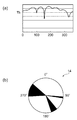
図2は、車輪14の回転角と、送受信機16と受信機20との通信状態の関係を示す。図2(a)は、車輪14の回転角と、送受信機16から送信された電波を受信機20が受信したときの強度の関係を示す。図2(b)は、車輪14の通信不良状態の回転角を示す。   FIG. 2 shows the relationship between the rotation angle of the wheel 14 and the communication state between the transceiver 16 and the receiver 20. FIG. 2A shows the relationship between the rotation angle of the wheel 14 and the intensity when the receiver 20 receives the radio wave transmitted from the transceiver 16. FIG. 2B shows the rotation angle of the communication failure state of the wheel 14.

図2(a)の縦軸は、受信機20が受信したときの電波強度を示し、横軸は車輪14の回転角を示す。電波強度Th以下であれば、受信機20の受信状態が不良となる。なお、車輪14の回転角と、送受信機16と受信機20との通信状態の関係は、車輪14のタイヤやホイールの種類、車種などの要因により変化する。   The vertical axis in FIG. 2A indicates the radio wave intensity when received by the receiver 20, and the horizontal axis indicates the rotation angle of the wheel 14. If the signal strength is less than Th, the reception state of the receiver 20 is poor. The relationship between the rotation angle of the wheel 14 and the communication state between the transceiver 16 and the receiver 20 varies depending on factors such as the tire of the wheel 14, the type of wheel, and the vehicle type.

図2(b)は、図2(a)に示す関係を車輪14上で展開したものである。図2(b)の黒色領域は、通信不良となる回転角を示す。車輪14の回転角が黒色領域に示される回転角にあれば、受信機20は、その車輪14の送受信機16から送信される応答信号を受信することができず、ECU100は、車輪14の位置を特定することができない。なお、発信機18と送受信機16との通信状態も、車輪14の回転角によって通信不良となる場合があり、返信要求信号が送受信機16に届かない場合がある。   FIG. 2B is a development of the relationship shown in FIG. A black region in FIG. 2B indicates a rotation angle that causes communication failure. If the rotation angle of the wheel 14 is in the rotation angle indicated in the black region, the receiver 20 cannot receive a response signal transmitted from the transmitter / receiver 16 of the wheel 14, and the ECU 100 determines the position of the wheel 14. Cannot be specified. In addition, the communication state between the transmitter 18 and the transmitter / receiver 16 may cause a communication failure depending on the rotation angle of the wheel 14, and the reply request signal may not reach the transmitter / receiver 16.

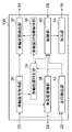
図3は、実施形態に係るECU100の機能構成を示す。ECU100は、車輪信号取得部30と、車輪状態検出部32と、車輪位置特定部34と、車輪識別情報保持部36と、未受信警報部38と、制御部40と、走行検出部42と、指示部44とを備える。   FIG. 3 shows a functional configuration of the ECU 100 according to the embodiment. The ECU 100 includes a wheel signal acquisition unit 30, a wheel state detection unit 32, a wheel position specification unit 34, a wheel identification information holding unit 36, a non-reception alarm unit 38, a control unit 40, a travel detection unit 42, And an instruction unit 44.

車輪信号取得部30は、受信機20が受信した車輪信号を取得する。車輪信号取得部30は、取得した車輪信号を車輪状態検出部32、車輪位置特定部34および未受信警報部38の少なくともいずれかに供給する。   The wheel signal acquisition unit 30 acquires the wheel signal received by the receiver 20. The wheel signal acquisition unit 30 supplies the acquired wheel signal to at least one of the wheel state detection unit 32, the wheel position specification unit 34, and the non-reception alarm unit 38.

車輪位置特定部34は、応答信号に含まれる車輪識別情報にもとづいて、車輪識別情報を送信した送受信機16が設けられている車輪14の位置を特定する。ここで、車輪位置特定処理について説明する。まず、制御部40により車輪位置特定処理を実行することが決定されると、指示部44が発信機18に返信要求信号の発信を指示する。発信機18Fと発信機18Rは、指示部44からの指示を受け、タイミングを異ならせて返信要求信号を発信する。前輪と後輪の送受信機16は、それぞれ返信要求信号を受信すると、その電波強度を測定し、車輪識別情報と受信強度とを含めた応答信号を生成し、送信する。車輪位置特定部34は、受信機20で受信した応答信号のタイミングによって、その応答信号が前輪または後輪のいずれから送信されたものであるか特定する。   The wheel position specifying unit 34 specifies the position of the wheel 14 provided with the transceiver 16 that has transmitted the wheel identification information, based on the wheel identification information included in the response signal. Here, the wheel position specifying process will be described. First, when the control unit 40 determines to execute the wheel position specifying process, the instruction unit 44 instructs the transmitter 18 to transmit a reply request signal. The transmitter 18F and the transmitter 18R receive an instruction from the instruction unit 44, and transmit a reply request signal at different timings. When each of the front wheel and rear wheel transceivers 16 receives the reply request signal, it measures the radio field intensity, generates a response signal including the wheel identification information and the reception intensity, and transmits it. The wheel position specifying unit 34 specifies whether the response signal is transmitted from the front wheel or the rear wheel according to the timing of the response signal received by the receiver 20.

また、車輪位置特定部34は、送受信機16から送信された受信強度を対比して、送受信機16から送信された車輪識別情報が左輪または右輪のいずれに対応するかを特定する。具体的には、発信機18Fからの返信要求信号を受信した送受信機16FLと送受信機16FRは、それぞれ受信した返信要求信号の受信強度を応答信号に含めて送信する。この受信強度は、発信機18から送受信機16までの距離に応じて定まる。発信機18Fから近い左輪の送受信機16FLの受信強度は、発信機18Fから遠い右輪の送受信機16FRの受信強度より大きくなる。そこで、車輪位置特定部34は、送受信機16FLおよび送受信機16FRから送信された2つの受信強度を対比して、2つの受信強度の差分が所定値以上であれば、大きい方の受信強度を示した送受信機16FLの車輪識別情報を左輪と特定し、小さい方の受信強度を示した送受信機16FRの車輪識別情報を右輪と特定する。以上のように、車輪位置特定部34は、前後輪の特定方法と、左右輪の特定方法を組み合わせて、各車輪14の全ての位置を特定する。   Further, the wheel position specifying unit 34 compares the reception intensity transmitted from the transmitter / receiver 16 and specifies whether the wheel identification information transmitted from the transmitter / receiver 16 corresponds to the left wheel or the right wheel. Specifically, the transmitter / receiver 16FL and the transmitter / receiver 16FR that have received the reply request signal from the transmitter 18F transmit the response signal including the reception strength of the received reply request signal. This reception intensity is determined according to the distance from the transmitter 18 to the transmitter / receiver 16. The reception intensity of the left wheel transmitter / receiver 16FL close to the transmitter 18F is larger than the reception intensity of the right wheel transmitter / receiver 16FR far from the transmitter 18F. Therefore, the wheel position specifying unit 34 compares the two received intensities transmitted from the transceiver 16FL and the transceiver 16FR, and indicates the larger received intensity if the difference between the two received intensities is a predetermined value or more. The wheel identification information of the transmitter / receiver 16FL is specified as the left wheel, and the wheel identification information of the transmitter / receiver 16FR indicating the smaller reception intensity is specified as the right wheel. As described above, the wheel position specifying unit 34 specifies all positions of each wheel 14 by combining the front and rear wheel specifying method and the left and right wheel specifying method.

車輪位置特定部34は、全ての車輪14の位置を特定すれば、車輪位置特定処理が完了したことを示す完了フラグを生成する。なお、車輪位置特定処理とは、制御部40における車輪位置特定処理の実行開始の契機から、各発信機18が返信要求信号を1回発信し、それに応じて送受信機16が応答信号を1回送信し、応答信号にもとづいて車輪位置特定部34が各車輪14の位置を特定しようとするまでの1回の試行をいう。   If the position of all the wheels 14 is specified, the wheel position specifying unit 34 generates a completion flag indicating that the wheel position specifying process has been completed. The wheel position specifying process means that each transmitter 18 transmits a reply request signal once, and the transmitter / receiver 16 sends a response signal once in response to the start of execution of the wheel position specifying process in the control unit 40. This means one trial until the wheel position specifying unit 34 tries to specify the position of each wheel 14 based on the response signal.

また、車輪位置特定部34は、車両走行中の車輪用センサ類28の加速度センサの出力にもとづいて走行輪とスペア車輪14SPとを区別する。車両走行中、加速度センサにより検出された加速度情報を含む車輪状態信号が各送受信機16から所定の通信周期で送信される。車両走行中、スペア車輪14SPは回転しないため、車輪用センサ類28SPの加速度センサの出力はほとんど変化しない。一方、走行輪の車輪用センサ類28の加速度センサの出力は、車両の走行中に大きく変化する。車輪位置特定部34は、車両10の走行を検出したときに、ほとんど変化のない加速度センサの出力を示す車輪状態情報とともに車輪状態信号に含まれていた車輪識別情報がスペア車輪14SPに対応すると特定する。なお、車輪位置特定部34は、車両走行に関する情報を走行検出部42から受け取ってよい。   Further, the wheel position specifying unit 34 distinguishes between the traveling wheel and the spare wheel 14SP based on the output of the acceleration sensor of the wheel sensors 28 while the vehicle is traveling. While the vehicle is running, a wheel state signal including acceleration information detected by the acceleration sensor is transmitted from each transceiver 16 at a predetermined communication cycle. Since the spare wheel 14SP does not rotate during traveling of the vehicle, the output of the acceleration sensor of the wheel sensors 28SP hardly changes. On the other hand, the output of the acceleration sensor of the wheel sensors 28 for the traveling wheels changes greatly during traveling of the vehicle. The wheel position specifying unit 34 specifies that the wheel identification information included in the wheel state signal together with the wheel state information indicating the output of the acceleration sensor having almost no change corresponds to the spare wheel 14SP when the traveling of the vehicle 10 is detected. To do. The wheel position specifying unit 34 may receive information related to vehicle travel from the travel detection unit 42.

以上より、車輪位置特定部34は、各車輪14の位置を特定し、車輪識別情報と車輪14の位置を関連づけて車輪識別情報保持部36に保持させる。なお、車輪位置特定部34は、各車輪14の位置を特定する他の既知の方法を用いてよい。たとえば、送受信機16から送信される車輪識別情報に右前輪などの車輪の位置を特定できる情報があらかじめ含まれていてよく、車輪位置特定部34はその情報をもとに各車輪14の位置を特定してよい。   From the above, the wheel position specifying unit 34 specifies the position of each wheel 14, associates the wheel identification information with the position of the wheel 14, and causes the wheel identification information holding unit 36 to hold the wheel identification information. The wheel position specifying unit 34 may use another known method for specifying the position of each wheel 14. For example, the wheel identification information transmitted from the transceiver 16 may include information that can identify the position of the wheel such as the right front wheel in advance, and the wheel position specifying unit 34 determines the position of each wheel 14 based on the information. May be specified.

車輪状態検出部32は、車輪信号取得部30から受け取った車輪状態情報から、各車輪14の状態を検出する。車輪状態検出部32は、車輪14の空気圧や温度に異常を検出すれば、警報装置24を介して運転者にその異常を伝達する。車輪状態検出部32は、車輪識別情報保持部36に保持される車輪14の位置を特定した情報をもとに、どの車輪14に異常が生じたのか検出する。   The wheel state detection unit 32 detects the state of each wheel 14 from the wheel state information received from the wheel signal acquisition unit 30. If the wheel state detection unit 32 detects an abnormality in the air pressure or temperature of the wheel 14, the wheel state detection unit 32 transmits the abnormality to the driver via the alarm device 24. The wheel state detection unit 32 detects which wheel 14 is abnormal based on the information specifying the position of the wheel 14 held in the wheel identification information holding unit 36.

未受信警報部38は、受信機20が送受信機16から定期的に送信されている車輪状態信号を受信していない場合に未受信情報を生成する。未受信警報部38は、送受信機16のうち少なくともひとつから、受信機20が車輪状態信号を受信できなければ、未受信情報を生成する。たとえば、車輪状態信号が1分周期で送信される場合に、未受信警報部38は、1分毎に車輪信号取得部30が新たな車輪状態信号を取得したかどうか判定する。そして、未受信警報部38は、車輪信号取得部30が新たな車輪状態信号を取得していなければ、未受信情報を生成する。未受信情報が生成されていなければ、車輪状態信号の通信周期である1分以内には送受信機16から受信機20の通信が成立しており、通信状況が良好である可能性が高い。なお、未受信警報部38は、受信機20が送受信機16から車輪状態信号を、たとえば20分以上継続して受信していない場合に、警報装置24を介して未受信警報を発してもよい。   The non-reception alarm unit 38 generates non-reception information when the receiver 20 has not received the wheel state signal periodically transmitted from the transceiver 16. The non-reception alarm unit 38 generates non-reception information if the receiver 20 cannot receive the wheel state signal from at least one of the transceivers 16. For example, when the wheel state signal is transmitted at a cycle of one minute, the non-reception alarm unit 38 determines whether the wheel signal acquisition unit 30 has acquired a new wheel state signal every minute. And the non-reception warning part 38 produces | generates non-reception information, if the wheel signal acquisition part 30 has not acquired a new wheel state signal. If unreceived information is not generated, communication between the transceiver 16 and the receiver 20 is established within one minute, which is the communication cycle of the wheel state signal, and there is a high possibility that the communication status is good. The non-reception alarm unit 38 may issue a non-reception alarm via the alarm device 24 when the receiver 20 has not continuously received the wheel state signal from the transceiver 16 for, for example, 20 minutes or more. .

走行検出部42は、車両10の走行を検出する。具体的には、走行検出部42は、車輪用センサ類28の加速度センサまたは車体用センサ類22の加速度センサの出力にもとづいて車両10の走行を検出する。   The travel detection unit 42 detects the travel of the vehicle 10. Specifically, the travel detection unit 42 detects the travel of the vehicle 10 based on the output of the acceleration sensor of the wheel sensors 28 or the acceleration sensor of the vehicle body sensor 22.

制御部40は、車輪位置特定処理を制御し、車輪位置特定部34が各車輪14の位置を特定したかどうかを判定する。制御部40は、車輪位置特定処理を最大で所定のセット回数実行して、車輪位置特定処理が完了していなければ、すなわち車輪位置特定部34が各車輪14の位置を特定できなければ、車輪位置特定処理が未完了であるとして、車輪位置特定処理を停止してよい。これにより、車輪位置特定処理が完了するまで車輪位置特定処理を繰り返し実行する場合と比べて、車輪位置特定処理にかかる電力消費を抑えることができる。送受信機16は電池駆動であるため、送受信機16の電力消費を抑えることは好ましい。   The control unit 40 controls the wheel position specifying process, and determines whether or not the wheel position specifying unit 34 has specified the position of each wheel 14. If the wheel position specifying process is not completed, that is, if the wheel position specifying unit 34 cannot specify the position of each wheel 14, the control unit 40 executes the wheel position specifying process at most a predetermined number of times. The wheel position specifying process may be stopped assuming that the position specifying process is incomplete. Thereby, compared with the case where a wheel position specific process is repeatedly performed until a wheel position specific process is completed, the power consumption concerning a wheel position specific process can be suppressed. Since the transceiver 16 is battery-driven, it is preferable to suppress the power consumption of the transceiver 16.

制御部40は、イグニッションスイッチ26がOFFからONにされた場合、すなわち停車時に車両の始動を検出した場合に、車輪位置特定処理を実行する。制御部40は、車両停止時に車輪位置特定部34が各車輪の位置を特定していないと判定する場合に、走行検出部42が車両の走行を検出したのちに、車輪位置特定処理を再実行する。これにより、車両停止時に車輪位置特定処理が完了しない場合であっても、車両10が動いて車輪14の回転角が変化したのちに車輪位置特定処理を再実行することができ、車輪位置特定処理を完了させる可能性を高めることができる。   The control unit 40 executes the wheel position specifying process when the ignition switch 26 is turned from OFF to ON, that is, when the start of the vehicle is detected when the vehicle is stopped. When it is determined that the wheel position specifying unit 34 has not specified the position of each wheel when the vehicle is stopped, the control unit 40 re-executes the wheel position specifying process after the travel detecting unit 42 detects the travel of the vehicle. To do. As a result, even if the wheel position specifying process is not completed when the vehicle is stopped, the wheel position specifying process can be re-executed after the vehicle 10 moves and the rotation angle of the wheel 14 is changed. Can increase the possibility of completing.

制御部40は、車輪位置特定部34が各車輪14の位置を特定していない場合に、受信機20が車輪状態信号を受信していれば、車輪位置特定処理を再実行する。制御部40は、受信機20が車輪状態信号を受信しているかどうか、未受信警報部38における未受信情報の生成の有無にもとづいて判定する。ここで、車輪14の回転角以外にも車輪位置特定処理が完了しない要因が予測される。たとえば、車両10の周囲に強い電波を発生する物が一時的に存在すれば、車輪位置特定処理が完了できない場合もある。未受信情報が生成されていなければ、少なくとも車輪状態信号の通信周期前までは送受信機16から受信機20への通信は良好であり、このときに車輪位置特定処理を再実行すれば、車輪位置特定処理を完了させる可能性を高めることができる。   If the wheel position specifying unit 34 has not specified the position of each wheel 14 and the receiver 20 has received a wheel state signal, the control unit 40 re-executes the wheel position specifying process. The control unit 40 determines whether or not the receiver 20 has received a wheel state signal based on whether or not unreceived information is generated in the unreceived alarm unit 38. Here, factors other than the rotation angle of the wheel 14 that the wheel position specifying process is not completed are predicted. For example, if an object that generates strong radio waves temporarily exists around the vehicle 10, the wheel position specifying process may not be completed. If unreceived information is not generated, communication from the transmitter / receiver 16 to the receiver 20 is good at least before the communication cycle of the wheel state signal, and if the wheel position specifying process is performed again at this time, the wheel position The possibility of completing the specific process can be increased.

制御部40は、車輪位置特定部34が各車輪14の位置を特定しない場合、所定時間の経過毎に車輪位置特定処理を再実行してよい。ここで、所定時間の経過毎に車輪位置特定処理を再実行する回数は、所定のループ回数であってよい。すなわち、上述の車輪位置特定処理の所定のセット回数の実行を1セットとして、この1セットの車輪位置特定処理を所定のループ回数繰り返す。たとえば、所定のセット回数を10回、所定時間を20分、所定のループ回数を3回とすれば、制御部40は、まず車両停車時に車輪位置特定処理を最大で10回実行し、走行開始時から20分毎に10回ずつ実行される車輪位置特定処理を最大で3回まで繰り返す。なお、制御部40は、この処理の途中で車輪位置特定処理が完了すれば、その時点で処理を終える。所定時間毎に車輪位置特定処理を所定のループ回数繰り返すことで、車輪位置特定処理をリトライして、車輪位置特定処理を完了させる可能性を高めることができる。なお、制御部40は、所定時間毎に受信機20が車輪状態信号を受信しているかどうか判定し、受信機20が車輪状態信号を受信している場合に、車輪位置特定処理の再実行を繰り返してよい。これにより、車輪位置特定処理を完了させる可能性を高い場合に、車輪位置特定処理をリトライすることができる。   When the wheel position specifying unit 34 does not specify the position of each wheel 14, the control unit 40 may re-execute the wheel position specifying process every time a predetermined time elapses. Here, the number of times the wheel position specifying process is re-executed every elapse of a predetermined time may be a predetermined number of loops. That is, the execution of the predetermined set number of times of the wheel position specifying process described above is set as one set, and this one set of wheel position specifying process is repeated a predetermined number of loops. For example, if the predetermined number of times is set to 10, the predetermined time is set to 20 minutes, and the predetermined number of loops is set to 3, the control unit 40 first executes the wheel position specifying process 10 times at the maximum when the vehicle stops, and starts running. The wheel position specifying process executed 10 times every 20 minutes from the time is repeated up to 3 times. In addition, if the wheel position specifying process is completed during the process, the control unit 40 ends the process at that time. By repeating the wheel position specifying process every predetermined time by a predetermined number of loops, the possibility of retrying the wheel position specifying process and completing the wheel position specifying process can be increased. Note that the control unit 40 determines whether or not the receiver 20 receives a wheel state signal every predetermined time. When the receiver 20 receives a wheel state signal, the control unit 40 re-executes the wheel position specifying process. You can repeat it. Thereby, when the possibility of completing the wheel position specifying process is high, the wheel position specifying process can be retried.

また、制御部40は、スペア車輪14SPを備える車両10において、車両10の走行を検出するまで、すなわちグランドスペアタイヤを特定するまで、車輪位置特定処理を実行しなくてよい。なお、車両10がグランドスペアタイヤを有するか否かは、あらかじめECU100に設定してよい。車両10がグランドスペアタイヤを有する場合には、発信機18Rが発信する返信要求信号に対して送受信機16SPが応答するため、グランドスペアタイヤが後輪の位置を特定する処理の阻害要因となる場合がある。そこで、車両10がグランドスペアタイヤを有する場合には、車両10の走行が検出されてグランドスペアタイヤが特定されるまで、車輪位置特定処理を実行しないことで、車輪位置特定処理にかかる電力消費をより抑えることができる。制御部40は、車輪位置特定処理を実行すると判定すれば、その判定結果を指示部44に供給する。   Moreover, the control part 40 does not need to perform a wheel position specific process in the vehicle 10 provided with the spare wheel 14SP until it detects driving | running | working of the vehicle 10, ie, until a grand spare tire is specified. Whether or not the vehicle 10 has a ground spare tire may be set in the ECU 100 in advance. When the vehicle 10 has a ground spare tire, the transmitter / receiver 16SP responds to a reply request signal transmitted from the transmitter 18R, and therefore the ground spare tire becomes an obstacle to the process of specifying the position of the rear wheel. There is. Therefore, when the vehicle 10 has a ground spare tire, the wheel position specifying process is not executed until the traveling of the vehicle 10 is detected and the ground spare tire is specified, thereby reducing the power consumption for the wheel position specifying process. It can be suppressed more. If it determines with performing the wheel position specific process, the control part 40 will supply the determination result to the instruction | indication part 44. FIG.

指示部44は、制御部40による判定結果に応じて、送受信機16に対して車輪識別情報を送信するように指示する。具体的に指示部44は、制御部40から車輪位置特定処理の実行するとの判定結果を受け、送受信機16が応答信号を送信するように発信機18に指示する。発信機18Fおよび発信機18Rは、指示部44からの指示を受けて交互に返信要求信号を発信し、送受信機16は、その返信要求信号に応じて応答信号を送信する。   The instruction unit 44 instructs the transmitter / receiver 16 to transmit the wheel identification information according to the determination result by the control unit 40. Specifically, the instruction unit 44 receives the determination result that the wheel position specifying process is to be executed from the control unit 40, and instructs the transmitter 18 that the transmitter / receiver 16 transmits a response signal. The transmitter 18F and the transmitter 18R alternately transmit a reply request signal in response to an instruction from the instruction unit 44, and the transceiver 16 transmits a response signal in response to the reply request signal.

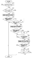
図4は、実施形態に係る各車輪14の位置を特定する処理を示すフローチャートである。まず、制御部40は、イグニッションスイッチ(IG)26がONされたかどうか判定する(S10)。制御部40は、イグニッションスイッチ26がONされていないと判定すれば(S10のN)、処理を終える。   FIG. 4 is a flowchart showing processing for specifying the position of each wheel 14 according to the embodiment. First, the control unit 40 determines whether the ignition switch (IG) 26 is turned on (S10). If it is determined that the ignition switch 26 is not turned on (N in S10), the control unit 40 ends the process.

制御部40は、イグニッションスイッチ26がONされたと判定すれば(S10のY)、車両10がグランドスペアタイヤを有するかどうかを判定する(S12)。   If it determines with the ignition switch 26 having been turned ON (Y of S10), the control part 40 will determine whether the vehicle 10 has a ground spare tire (S12).

制御部40は、車両10がグランドスペアタイヤを有しないと判定すれば(S12のN)、車輪位置特定処理の実行を開始させる(S14)。ここで、車輪位置特定処理が最大で所定のセット回数実行されてよい。   If it determines with the vehicle 10 not having a grand spare tire (N of S12), the control part 40 will start execution of a wheel position specific process (S14). Here, the wheel position specifying process may be executed a predetermined number of times at maximum.

制御部40は、車輪位置特定処理が完了したかどうか、すなわち車輪位置特定部34が各車輪14の位置を全て特定することができたかを判定する(S16)。制御部40は、車輪位置特定処理が完了したと判定すれば(S16のY)、処理を終える。   The control unit 40 determines whether or not the wheel position specifying process has been completed, that is, whether or not the wheel position specifying unit 34 has specified all the positions of the wheels 14 (S16). If it determines with the control part 40 having completed the wheel position specific process (Y of S16), a process will be complete | finished.

制御部40は、車輪位置特定処理が未完了であると判定すれば(S16のN)、走行検出部42が車両10の走行を検出したかどうかを判定する(S18)。また、制御部40は、車両10がグランドスペアタイヤを有すると判定すれば(S12のY)、走行検出部42が車両10の走行を検出したかどうかを判定する(S18)。制御部40は、走行検出部42が車両10の走行を検出するまで判定する(S18のN)。制御部40は、走行検出部42が車両10の走行を検出したと判定すれば(S18のY)、車輪位置特定処理を実行する(S20)。これにより、車輪14の回転角が変化した状態で車輪位置特定処理を実行することができる。また、車両走行時にグランドスペアタイヤを特定し、グランドスペアタイヤを除いた走行輪に対して車輪位置特定処理を実行することができる。ここで、車輪位置特定処理が最大で所定のセット回数実行されてよい。   If it is determined that the wheel position specifying process has not been completed (N in S16), the control unit 40 determines whether the traveling detection unit 42 has detected the traveling of the vehicle 10 (S18). If it is determined that the vehicle 10 has a ground spare tire (Y in S12), the control unit 40 determines whether the travel detection unit 42 has detected the travel of the vehicle 10 (S18). The control unit 40 determines until the traveling detection unit 42 detects the traveling of the vehicle 10 (N in S18). If it determines with the driving | running | working detection part 42 having detected driving | running | working of the vehicle 10 (Y of S18), the control part 40 will perform a wheel position specific process (S20). Thereby, a wheel position specific | specification process can be performed in the state which the rotation angle of the wheel 14 changed. In addition, it is possible to specify the ground spare tire when the vehicle is traveling and to execute the wheel position specifying process on the traveling wheels excluding the ground spare tire. Here, the wheel position specifying process may be executed a predetermined number of times at maximum.

制御部40は、車輪位置特定処理が完了したかどうかを判定する(S22)。制御部40は、車輪位置特定処理が完了したと判定すれば(S22のY)、処理を終える。   The control unit 40 determines whether the wheel position specifying process is completed (S22). If it is determined that the wheel position specifying process has been completed (Y in S22), the control unit 40 ends the process.

制御部40は、車輪位置特定処理が未完了であると判定すれば(S22のN)、ループ回数iを0とする(S24)。制御部40は、受信機20が車輪状態信号を受信していないことを示す未受信情報が生成されたかどうかを判定する(S26)。すなわち、制御部40は、受信機20が車輪状態信号を受信しているかどうかを判定する。制御部40は、未受信情報が生成されたと判定すれば(S26のY)、所定時間を経過毎に未受信情報が生成されたかどうかを判定する処理を繰り返す。   If it is determined that the wheel position specifying process has not been completed (N in S22), the control unit 40 sets the loop count i to 0 (S24). The control unit 40 determines whether or not unreceived information indicating that the receiver 20 has not received the wheel state signal has been generated (S26). That is, the control unit 40 determines whether or not the receiver 20 has received a wheel state signal. If it is determined that the unreceived information has been generated (Y in S26), the control unit 40 repeats the process of determining whether the unreceived information has been generated every predetermined time.

制御部40は、未受信情報が生成されていないと判定すれば(S26のN)、車輪位置特定処理の実行する(S28)。これにより、通信状況が良好とされる場合に車輪位置特定処理を実行することで、車輪位置特定処理を完了させる可能性を高めることができる。ここで、車輪位置特定処理が最大で所定のセット回数実行されてよい。   If it determines with the non-received information not being produced | generated (N of S26), the control part 40 will perform a wheel position specific process (S28). Thereby, the possibility of completing the wheel position specifying process can be increased by executing the wheel position specifying process when the communication status is good. Here, the wheel position specifying process may be executed a predetermined number of times at maximum.

制御部40は、車輪位置特定処理が完了したかどうかを判定する(S30)。制御部40は、車輪位置特定処理が完了したと判定すれば(S30のY)、処理を終える。制御部40は、車輪位置特定処理が未完了であると判定すれば(S30のN)、ループ回数iをインクリメントする(S32)。制御部40は、ループ回数iが所定のループ回数Nに達したかどうか判定する(S34)。制御部40は、ループ回数iが所定のループ回数Nに達するまで、車輪位置特定処理を繰り返す(S34のN)。制御部40は、ループ回数iが所定のループ回数Nに達したと判定すれば(S34のY)、処理を終える。所定時間毎に車輪位置特定処理の繰り返し回数に上限を設定することで、電力消費を抑えることができる。   The control unit 40 determines whether the wheel position specifying process is completed (S30). If it is determined that the wheel position specifying process has been completed (Y in S30), the control unit 40 ends the process. If it is determined that the wheel position specifying process is not completed (N in S30), the control unit 40 increments the loop count i (S32). The control unit 40 determines whether or not the loop count i has reached a predetermined loop count N (S34). The control unit 40 repeats the wheel position specifying process until the loop count i reaches a predetermined loop count N (N in S34). If it is determined that the loop count i has reached the predetermined loop count N (Y in S34), the control unit 40 ends the process. By setting an upper limit to the number of repetitions of the wheel position specifying process every predetermined time, power consumption can be suppressed.

以上、実施の形態をもとに本発明を説明した。これらの実施形態は例示であり、各構成要素にいろいろな変形例が可能なこと、またそうした変形例も本発明の範囲にあることは当業者に理解されるところである。   The present invention has been described above based on the embodiment. It is to be understood by those skilled in the art that these embodiments are exemplifications, and that various modifications are possible for each component, and that such modifications are also within the scope of the present invention.

たとえば、車輪位置特定部34は、車輪位置特定処理が完了したことを示す完了フラグを前輪と後輪に分けて、それぞれ独立に生成してよい。すなわち、車輪位置特定部34は、前輪の完了フラグと後輪の完了フラグを生成する。このとき、それぞれの完了フラグの生成に応じて車輪位置特定処理を終えてよい。これにより、車輪位置特定処理における電力消費を抑えることができる。   For example, the wheel position specifying unit 34 may divide the completion flag indicating that the wheel position specifying process has been completed into a front wheel and a rear wheel, and independently generate them. That is, the wheel position specifying unit 34 generates a front wheel completion flag and a rear wheel completion flag. At this time, the wheel position specifying process may be completed according to the generation of each completion flag. Thereby, the power consumption in the wheel position specifying process can be suppressed.

また、制御部40は、車輪位置特定処理を所定のループ回数試行しても、車輪位置特定処理が未完了であれば、警報装置24を介して車輪位置特定処理が未完了であることを運転者に伝達してよい。   Further, if the wheel position specifying process is incomplete even if the wheel position specifying process is tried a predetermined number of loops, the control unit 40 determines that the wheel position specifying process is incomplete via the alarm device 24. May be communicated to the person.

実施形態に係る車輪位置特定システムの全体構成図である。It is a whole lineblock diagram of the wheel position specific system concerning an embodiment. 車輪の回転角と、送受信機と受信機との通信状態の関係を示す図である。図2(a)は、車輪の回転角と、送受信機から送信された電波を受信機が受信したときの強度の関係を示す。図2(b)は、車輪の通信不良状態の回転角を示す。It is a figure which shows the relationship between the rotation angle of a wheel, and the communication state of a transmitter / receiver and a receiver. FIG. 2A shows the relationship between the rotation angle of the wheel and the intensity when the receiver receives the radio wave transmitted from the transceiver. FIG.2 (b) shows the rotation angle of the communication failure state of a wheel. 実施形態に係るECUの機能構成を示す図である。It is a figure which shows the function structure of ECU which concerns on embodiment. 実施形態に係る各車輪の位置を特定する処理を示すフローチャートである。It is a flowchart which shows the process which pinpoints the position of each wheel which concerns on embodiment.

符号の説明Explanation of symbols

10 車両、 12 車両本体、 14 車輪、 16 送受信機、 18 発信機、 20 受信機、 22 車体用センサ類、 24 警報装置、 26 イグニッションスイッチ、 28 車輪用センサ類、 30 車輪信号取得部、 32 車輪状態検出部、 34 車輪位置特定部、 36 車輪識別情報保持部、 38 未受信警報部、 40 制御部、 42 走行検出部、 44 指示部、 100 ECU、 200 車輪位置特定システム。   DESCRIPTION OF SYMBOLS 10 Vehicle, 12 Vehicle body, 14 Wheel, 16 Transmitter / receiver, 18 Transmitter, 20 Receiver, 22 Body sensor, 24 Alarm device, 26 Ignition switch, 28 Wheel sensor, 30 Wheel signal acquisition unit, 32 Wheel State detection unit, 34 wheel position specifying unit, 36 wheel identification information holding unit, 38 unreceived alarm unit, 40 control unit, 42 traveling detection unit, 44 indicating unit, 100 ECU, 200 wheel position specifying system.

Claims (5)

車輪位置特定処理を実行する車輪位置特定システムであって、
各車輪に設けられ、車輪の識別情報を送信する送信機と、
各車輪が装着された車両本体に設けられ、前記識別情報を受信する受信機と、
前記識別情報にもとづいて、前記識別情報を送信した前記送信機が設けられている車輪の位置を特定する車輪位置特定手段と、
前記車輪位置特定処理を制御し、前記車輪位置特定手段が各車輪の位置を特定したかどうかを判定する制御手段と、
車両の走行を検出する車両走行検出手段と、を備え、
前記制御手段は、車両停止時に前記車輪位置特定手段が各車輪の位置を特定していないと判定する場合に、前記車両走行検出手段が車両の走行を検出したのちに、前記車輪位置特定処理を再実行することを特徴とする車輪位置特定システム。
A wheel position specifying system for executing wheel position specifying processing,
A transmitter provided on each wheel for transmitting the wheel identification information;
A receiver that is provided in a vehicle main body to which each wheel is mounted, and that receives the identification information;
Wheel position specifying means for specifying the position of the wheel provided with the transmitter that has transmitted the identification information based on the identification information;
Control means for controlling the wheel position specifying process, and determining whether the wheel position specifying means specified the position of each wheel;
Vehicle running detection means for detecting the running of the vehicle,
When the control unit determines that the wheel position specifying unit does not specify the position of each wheel when the vehicle is stopped, the control unit performs the wheel position specifying process after the vehicle travel detecting unit detects the travel of the vehicle. A wheel location system characterized by re-execution.
前記制御手段は、前記車輪位置特定処理を所定回数実行して、各車輪の位置を特定できなければ、前記車輪位置特定処理を停止することを特徴とする請求項1に記載の車輪位置特定システム。   The wheel position specifying system according to claim 1, wherein the control means executes the wheel position specifying process a predetermined number of times, and stops the wheel position specifying process if the position of each wheel cannot be specified. . 前記送信機は、前記車輪位置特定処理における送信処理とは別に、車輪に設けられたセンサにより検出された車輪状態情報を所定周期で前記受信機に送信し、
前記制御手段は、前記車輪位置特定手段が各車輪の位置を特定していない場合に、前記受信機が前記車輪状態情報を受信していれば、前記車輪位置特定処理を再実行することを特徴とする請求項1または2に記載の車輪位置特定システム。
The transmitter transmits wheel state information detected by a sensor provided on a wheel to the receiver at a predetermined period, separately from the transmission process in the wheel position specifying process,
The control means re-executes the wheel position specifying process if the receiver has received the wheel state information when the wheel position specifying means has not specified the position of each wheel. The wheel position specifying system according to claim 1 or 2.
前記車輪位置特定手段は、各車輪に設けられる加速度センサの出力にもとづいて走行輪とスペアタイヤとを区別することを特徴とする請求項1〜3のいずれかに記載の車輪位置特定システム。   The wheel position specifying system according to any one of claims 1 to 3, wherein the wheel position specifying means distinguishes a traveling wheel and a spare tire based on an output of an acceleration sensor provided on each wheel. 前記制御手段は、前記スペアタイヤを備える車両において、前記スペアタイヤを特定するまで、前記車輪位置特定処理を実行しないことを特徴とする請求項4に記載の車輪位置特定システム。   The wheel position specifying system according to claim 4, wherein the control unit does not execute the wheel position specifying process until the spare tire is specified in a vehicle including the spare tire.
JP2008324570A 2008-12-19 2008-12-19 Wheel position specifying system Pending JP2010143485A (en)

Priority Applications (1)

Application Number Priority Date Filing Date Title
JP2008324570A JP2010143485A (en) 2008-12-19 2008-12-19 Wheel position specifying system

Applications Claiming Priority (1)

Application Number Priority Date Filing Date Title
JP2008324570A JP2010143485A (en) 2008-12-19 2008-12-19 Wheel position specifying system

Publications (1)

Publication Number Publication Date
JP2010143485A true JP2010143485A (en) 2010-07-01

Family

ID=42564353

Family Applications (1)

Application Number Title Priority Date Filing Date
JP2008324570A Pending JP2010143485A (en) 2008-12-19 2008-12-19 Wheel position specifying system

Country Status (1)

Country Link
JP (1) JP2010143485A (en)

Cited By (4)

* Cited by examiner, † Cited by third party
Publication number Priority date Publication date Assignee Title
JP2012144223A (en) * 2011-01-14 2012-08-02 Tokai Rika Co Ltd System for monitoring tire pneumatic pressure
WO2013187016A1 (en) * 2012-06-11 2013-12-19 株式会社デンソー Wheel location detector device and tire air pressure detector device comprising same
JP2016022888A (en) * 2014-07-23 2016-02-08 太平洋工業株式会社 Tire condition monitoring device
JP2016144961A (en) * 2015-02-06 2016-08-12 トヨタ自動車株式会社 Tire pressure sensor unit, tire pressure notification device and vehicle

Cited By (6)

* Cited by examiner, † Cited by third party
Publication number Priority date Publication date Assignee Title
JP2012144223A (en) * 2011-01-14 2012-08-02 Tokai Rika Co Ltd System for monitoring tire pneumatic pressure
WO2013187016A1 (en) * 2012-06-11 2013-12-19 株式会社デンソー Wheel location detector device and tire air pressure detector device comprising same
JP2013256157A (en) * 2012-06-11 2013-12-26 Denso Corp Wheel position detecting device and tire air pressure detecting device including the same
JP2016022888A (en) * 2014-07-23 2016-02-08 太平洋工業株式会社 Tire condition monitoring device
JP2016144961A (en) * 2015-02-06 2016-08-12 トヨタ自動車株式会社 Tire pressure sensor unit, tire pressure notification device and vehicle
US10093139B2 (en) 2015-02-06 2018-10-09 Toyota Jidosha Kabushiki Kaisha Tire-pressure sensor unit, a tire-pressure notification device, and vehicle

Similar Documents

Publication Publication Date Title
JP4650077B2 (en) Wheel state acquisition device
JP4270284B2 (en) Wheel state monitoring system and wheel state detection device
JP5186475B2 (en) Tire condition monitoring device with keyless entry function
JP2008074163A (en) Tire air pressure detecting device
JP4810894B2 (en) Vehicle body side communication device for receiving tire pressure information, tire pressure transmitter for detecting and transmitting tire pressure of own wheel, and tire pressure monitoring system
JP5181965B2 (en) Wheel position detecting device and tire air pressure detecting device having the same
US7750798B2 (en) Wheel position detecting device that verifies accuracy of detection using trigger signal reception strength and tire air pressure detecting device including the same
JP4924189B2 (en) Wheel position detecting device and tire air pressure detecting device having the same
JP2008273477A (en) Vehicle sensor system
JP4218586B2 (en) Tire pressure detector
JP2010143485A (en) Wheel position specifying system
WO2020075776A1 (en) Tire pressure monitoring system
JP2006007902A (en) Tire state monitoring device
KR101850638B1 (en) Wheel assembly rotational position identifying apparatus
JP5018220B2 (en) Wheel position detecting device and tire air pressure detecting device having the same
JP2008024169A (en) Tire air pressure monitoring system
JP2010241384A (en) Tire air pressure monitoring system and tire air pressure monitoring unit
JP2013222428A (en) Tire air pressure detection device
JP4677808B2 (en) Wheel mounting position determination device, wheel position information setting device, and wheel information acquisition device
JP2016022889A (en) Tire condition monitoring device
JP5082375B2 (en) Detection target wheel identification system of the wheel state detection unit
JP2008112372A (en) Wheel status monitoring system and wheel information transmitting device
JP2006327324A (en) Tire state monitoring device
JP4984901B2 (en) Wheel condition monitoring system
JP2008080897A (en) Wheel information transmitting device, wheel condition monitoring system and wheel condition monitoring method