JP2010143369A - Pneumatic tire - Google Patents
Pneumatic tire Download PDFInfo
- Publication number
- JP2010143369A JP2010143369A JP2008322058A JP2008322058A JP2010143369A JP 2010143369 A JP2010143369 A JP 2010143369A JP 2008322058 A JP2008322058 A JP 2008322058A JP 2008322058 A JP2008322058 A JP 2008322058A JP 2010143369 A JP2010143369 A JP 2010143369A
- Authority
- JP
- Japan
- Prior art keywords
- belt
- tire
- width direction
- steel cord
- carcass
- Prior art date
- Legal status (The legal status is an assumption and is not a legal conclusion. Google has not performed a legal analysis and makes no representation as to the accuracy of the status listed.)
- Pending
Links
- 229910000831 Steel Inorganic materials 0.000 claims description 35
- 239000010959 steel Substances 0.000 claims description 35
- 239000011324 bead Substances 0.000 claims description 13
- 230000000694 effects Effects 0.000 description 4
- 239000010432 diamond Substances 0.000 description 3
- 229910003460 diamond Inorganic materials 0.000 description 2
- 239000000945 filler Substances 0.000 description 2
- 238000005259 measurement Methods 0.000 description 1
- 238000000034 method Methods 0.000 description 1
- 230000003014 reinforcing effect Effects 0.000 description 1
- 239000007787 solid Substances 0.000 description 1
Images

Landscapes
- Tires In General (AREA)
Abstract
Description
本発明は、空気入りタイヤに関し、更に詳しくは、氷路面上の走行性能および乾燥した通常の路面上の走行性能との両立を図ることができる空気入りタイヤに関する。 The present invention relates to a pneumatic tire, and more particularly to a pneumatic tire capable of achieving both running performance on an icy road surface and running performance on a dry normal road surface.
一般に、JATMA(社団法人 日本自動車タイヤ協会)の最大荷重における接地幅を100%とした場合、乗用車の前輪に装着した空気入りタイヤの接地幅は75〜85%程度で使用されている。 In general, when the contact width at the maximum load of JATMA (Japan Automobile Tire Association) is 100%, the contact width of a pneumatic tire attached to the front wheel of a passenger car is about 75 to 85%.
一方、四輪駆動車やSUV(スポーツ・ユーティリティ・ビークル)では、前輪に装着した空気入りタイヤは55〜65%という低い接地幅である。 On the other hand, in a four-wheel drive vehicle and SUV (Sports Utility Vehicle), a pneumatic tire attached to the front wheel has a low ground contact width of 55 to 65%.
ここで、接地幅が小さいと、氷路面上の走行性能が低下するため、特に、四輪駆動車やSUV等の車両では接地面積を高めることによって、氷路面上の走行性能を向上させることが求められている。 Here, if the ground contact width is small, the running performance on the icy road surface is lowered. In particular, in a vehicle such as a four-wheel drive vehicle or an SUV, the running performance on the icy road surface can be improved by increasing the ground contact area. It has been demanded.
通常、カーカスの頂部には、2層のベルト層が設けられており、トレッド部の剛性を保持しており(例えば、特許文献1参照)、このベルト層の剛性を適宜変更することによって接地面積を変えることができる。
しかしながら、前述した従来の空気入りタイヤでは、2層のベルト層によってトレッド部の剛性は向上するが、トレッド部のみならず、ショルダー部の剛性も向上するため、タイヤの接地幅が小さくなり、氷路面上の走行性能が低下するおそれがあった。 However, in the conventional pneumatic tire described above, the rigidity of the tread portion is improved by the two belt layers, but not only the tread portion but also the rigidity of the shoulder portion is improved. There is a possibility that the running performance on the road surface may be deteriorated.
そこで、本発明は、このような状況に鑑みてなされたものであり、氷路面上の走行性能および乾燥した通常の路面上の走行性能との両立を図ることができる空気入りタイヤを提供することを目的とする。 Therefore, the present invention has been made in view of such a situation, and provides a pneumatic tire capable of achieving both running performance on an icy road surface and running performance on a dry normal road surface. With the goal.
前述した課題を解決するため、本発明は、次のような特徴を有している。 In order to solve the above-described problems, the present invention has the following features.
まず、本発明の第1の特徴において、タイヤ幅方向に離間して配置された一対のビード部(ビード部9,9)と、一対のビード部同士をクラウン状に結ぶカーカス(カーカス3)と、該カーカスの頂部のタイヤ径方向外側に配設されたベルト層(ベルト層4)と、カーカスを覆うように配設されたトレッド部(トレッド部5)およびサイドウォール部(サイドウォール部6)とを備えた空気入りタイヤ(空気入りタイヤ1)であって、ベルト層は、カーカスの頂部のタイヤ径方向外側に配置された第1ベルト(第1ベルト10)と、該第1ベルトのタイヤ径方向外側に配置され、タイヤ幅方向に沿った幅寸法が第1ベルトよりも小さく形成された第2ベルト(第2ベルト11)とからなり、この第2ベルトのタイヤ幅方向両側における幅方向端縁(幅方向端縁11a)は、第1ベルトの幅方向端縁(幅方向端縁10a)からタイヤ幅方向内側に向けて10〜15mmの範囲に位置している。
First, in the first feature of the present invention, a pair of bead portions (bead
このように、第2ベルトの幅寸法を第1ベルトの幅寸法よりも小さくして有効ベルト幅を小さく設定することにより、ショルダー部におけるタイヤの剛性を低下させて接地面積を拡大させ、氷路面上の走行性能および通常の路面上の走行性能を向上させることができる。 Thus, by setting the width dimension of the second belt smaller than the width dimension of the first belt and setting the effective belt width small, the rigidity of the tire at the shoulder portion is reduced, the ground contact area is expanded, and the icy road surface It is possible to improve the running performance on the road and the running performance on the normal road surface.
その他の特徴において、ベルト層(ベルト層4)を構成する第1ベルト(第1ベルト10)および第2ベルト(第2ベルト11)には、それぞれ複数のスチールコードが設けられており、第2ベルトに設けられたスチールコード(スチールコード22)の引張強度は、第1ベルトに設けられたスチールコード(スチールコード21)の引張強度よりも大きい値に設定されている。 In other features, the first belt (first belt 10) and the second belt (second belt 11) constituting the belt layer (belt layer 4) are provided with a plurality of steel cords, respectively. The tensile strength of the steel cord (steel cord 22) provided on the belt is set to a value larger than the tensile strength of the steel cord (steel cord 21) provided on the first belt.
その他の特徴において、第2ベルト(第2ベルト11)におけるスチールコードのタイヤ周方向に対する交差角θ2を、第1ベルト(第1ベルト10)におけるスチールコードのタイヤ周方向に対する交差角θ1よりも大きく設定している。 In other features, the crossing angle θ2 of the steel cord in the second belt (second belt 11) with respect to the tire circumferential direction is larger than the crossing angle θ1 of the steel cord in the first belt (first belt 10) with respect to the tire circumferential direction. It is set.
その他の特徴において、第2ベルト(第2ベルト11)のタイヤ幅方向両側における幅方向端縁(幅方向端縁11a)は、第1ベルト(第1ベルト10)の幅方向端縁(幅方向端縁10a)からタイヤ幅方向内側に向けて5〜15mmの範囲に位置している。
In other features, the width direction edge (
本発明によれば、氷路面上の走行性能および乾燥した通常の路面上の走行性能との両立を図ることができる空気入りタイヤを提供することができる。 ADVANTAGE OF THE INVENTION According to this invention, the pneumatic tire which can aim at coexistence with the driving | running | working performance on an ice road surface and the driving | running | working performance on the normal dry road surface can be provided.
次に、本発明に係る空気入りタイヤの実施形態について、図面を参照しながら説明する。なお、以下の図面の記載において、同一または類似の部分には、同一または類似の符号を付している。ただし、図面は概略的なものであり、各寸法の比率などは現実のものとは異なることに留意すべきである。 Next, an embodiment of a pneumatic tire according to the present invention will be described with reference to the drawings. In the following description of the drawings, the same or similar parts are denoted by the same or similar reference numerals. However, it should be noted that the drawings are schematic and ratios of dimensions and the like are different from actual ones.
したがって、具体的な寸法などは以下の説明を参酌して判断すべきものである。また、図面相互間においても互いの寸法の関係や比率が異なる部分が含まれていることは勿論である。 Accordingly, specific dimensions and the like should be determined in consideration of the following description. Moreover, it is a matter of course that portions having different dimensional relationships and ratios are included between the drawings.
[第1実施形態]
まず、本発明の第1実施形態について説明する。
[First embodiment]
First, a first embodiment of the present invention will be described.
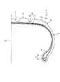
図1は、本発明の第1実施形態による空気入りタイヤのタイヤ幅方向の断面図である。 FIG. 1 is a sectional view in the tire width direction of a pneumatic tire according to a first embodiment of the present invention.
この空気入りタイヤ1は、タイヤ幅方向に離間して配置された一対の円環状のビードコア2,2と、これらのビードコア同士2,2をクラウン状に結ぶカーカス3と、該カーカス3の頂部上に配置されたベルト層4と、カーカス3の頂部に設けられたトレッド部5と、該トレッド部5のタイヤ幅方向両側に形成されたショルダー部12およびサイドウォール部6とを備えている。トレッド部5には、タイヤ周方向に延びる周方向溝7が形成されている。また、ビードコア2のタイヤ径方向外側には、ビードフィラ8が配設されており、これらのビードコア2とビードフィラ8とによってビード部9が構成されている。なお、図1中、CLはタイヤ赤道線である。
The pneumatic tire 1 includes a pair of
図1,2に示すように、ベルト層4は、カーカス3の上(即ち、タイヤ径方向外側)に載置された第1ベルト10と、該第1ベルト10の上(即ち、タイヤ径方向外側)に載置された第2ベルト11とから構成されており、第2ベルト11の幅寸法は、第1ベルト10の幅寸法よりも狭く形成されている。具体的には、タイヤ幅方向両側において、第2ベルト11の幅方向端縁11aは、第1ベルト10の幅方向端縁10aよりもタイヤ幅方向内側に配置されている。また、第1ベルト10の幅方向端縁10aと第2ベルト11の幅方向端縁11aとのタイヤ幅方向に沿った距離の差Dは、10〜15mmに設定されているここで、前記Dの距離が10mm未満の場合は、氷路面上の走行性能が低下するという問題があり、前記Dの距離が15mmよりも大きい場合は、乾燥した通常の路面上又は濡れた路面上の走行性能が低下するという問題がある。
As shown in FIGS. 1 and 2, the belt layer 4 includes a
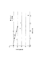
図3は、本発明の第1実施形態による有効ベルト幅寸法に対する接地幅比を示すグラフであり、車両の前輪に装着した空気入りタイヤについて示したものである。 FIG. 3 is a graph showing a contact width ratio with respect to an effective belt width dimension according to the first embodiment of the present invention, and shows a pneumatic tire mounted on a front wheel of a vehicle.
このグラフでは、内部が黒塗りされた菱形は、ベルト層4の上に図外のキャップを配設した空気入りタイヤについて示しており、内部が白抜きの菱形は、ベルト層4の上にキャップを配設し、該キャップの端部上を覆う図外の補助層が設けられた空気入りタイヤについて示している。また、縦軸については、内圧が200kPaで荷重が9.32kNの条件における車両前輪の接地幅を、JATMA最大荷重時の接地幅で割った比率を示している。横軸は、車両の前輪に空気入りタイヤを組み付けたときの有効ベルト幅である。ここで、有効ベルト幅とは、実車の接地幅に対する第2ベルトの幅寸法の比率を示す。測定に用いたタイヤのタイヤサイズは、265/70R16であり、タイヤの内圧は200kPaであり、荷重は5.32kNである。 In this graph, a diamond with a black interior shows a pneumatic tire in which a cap (not shown) is arranged on the belt layer 4, and a diamond with a white inside shows a cap on the belt layer 4. And a pneumatic tire provided with an auxiliary layer (not shown) covering the end of the cap. The vertical axis represents the ratio obtained by dividing the ground contact width of the vehicle front wheel under the conditions of an internal pressure of 200 kPa and a load of 9.32 kN by the ground contact width at the maximum load of JATMA. The horizontal axis represents the effective belt width when a pneumatic tire is assembled to the front wheel of the vehicle. Here, the effective belt width indicates the ratio of the width dimension of the second belt to the ground contact width of the actual vehicle. The tire size of the tire used for the measurement is 265 / 70R16, the internal pressure of the tire is 200 kPa, and the load is 5.32 kN.
このグラフによれば、第2ベルトの幅寸法が小さくなると、接地幅が向上することが判る。 According to this graph, it can be seen that when the width dimension of the second belt is reduced, the ground contact width is improved.
<作用・効果>
ベルト層4は、カーカス3の頂部のタイヤ径方向外側に配置された第1ベルト10と、該第1ベルト10のタイヤ径方向外側に配置され、タイヤ幅方向に沿った幅寸法が第1ベルト10よりも小さく形成された第2ベルト11とからなり、この第2ベルト11のタイヤ幅方向両側における幅方向端縁11aは、第1ベルト10の幅方向端縁10aからタイヤ幅方向内側に向けて10〜15mmの範囲に位置している。
<Action / Effect>
The belt layer 4 is disposed on the outer side in the tire radial direction of the top portion of the
このように、第2ベルト11の幅寸法を第1ベルト10の幅寸法よりも小さくして有効ベルト幅を小さく設定することにより、ショルダー部12におけるタイヤの剛性を低下させて接地面積を拡大させ、氷路面上の走行性能を向上させることができる。
Thus, by setting the width dimension of the
[第2実施形態]
次いで、本発明の第2実施形態について説明する。
[Second Embodiment]
Next, a second embodiment of the present invention will be described.
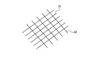
図4は、本発明の第2実施形態によるベルト層のスチールコードを示す概略図である。 FIG. 4 is a schematic view showing a steel cord of a belt layer according to a second embodiment of the present invention.
第1実施形態で説明したベルト層4を構成する第1ベルト10および第2ベルト11には、図4に示すように、それぞれ複数のスチールコードが設けられている。第1ベルト10内に配設された複数のスチールコード21と第2ベルト11内に配設された複数のスチールコード22とは互いに交差して配置されている。また、第2ベルト11に設けられたスチールコード22の引張強度は、第1ベルト10に設けられたスチールコード21の引張強度よりも大きい値に設定されている。
As shown in FIG. 4, each of the
<作用・効果>
本実施形態では、第2ベルト11に設けられたスチールコード22の引張強度は、第1ベルト10に設けられたスチールコード21の引張強度よりも大きい値に設定されている。従って、第1実施形態において第2ベルト11の幅寸法を第1ベルト10の幅よりも小さくしたことで低下したタイヤ剛性を向上させることができる。これにより、乾燥した通常の路面上の走行性能を向上させることができる。
<Action / Effect>
In the present embodiment, the tensile strength of the
[第3実施形態]
次いで、本発明の第3実施形態について説明する。
[Third embodiment]
Next, a third embodiment of the present invention will be described.
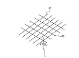
図5は、本発明の第3実施形態によるベルト層のスチールコードを示す概略図である。 FIG. 5 is a schematic view showing a steel cord of a belt layer according to a third embodiment of the present invention.
第1ベルト10におけるスチールコード21の延設方向は、タイヤ周方向Lに対してθ1の交差角をもって交差している。また、第2ベルト11におけるスチールコード22のタイヤ周方向Lに対する交差角はθ2である。この交差角θ2を交差角θ1よりも大きく設定している。
The extending direction of the
<作用・効果>
本実施形態では、交差角θ2を交差角θ1よりも大きく設定しているため、車両走行時において車両に横方向の荷重がかかった場合に、横力に対する抗力が増大してタイヤ変形を抑制することができる。即ち、第2ベルト11の引張強度を第1ベルト10の引張強度よりも大きくすることによって、ショルダー部12の剛性が低下して車両の直進走行性が低下するが、交差角θ2を交差角θ1よりも大きく設定することによって、その直進走行性が低下を抑制することができる。
<Action / Effect>
In the present embodiment, since the intersection angle θ2 is set to be larger than the intersection angle θ1, when a lateral load is applied to the vehicle during traveling of the vehicle, the resistance against the lateral force is increased to suppress tire deformation. be able to. That is, by making the tensile strength of the
<その他の実施形態>
前述したように、本発明の実施形態を通じて本発明の内容を開示したが、この開示の一部をなす論述及び図面は、本発明を限定するものであると理解すべきではない。この開示から当業者には様々な代替実施の形態、実施例及び運用技術が明らかとなろう。例えば、ベルト層4の上にキャップや補強層を設けても良い。
<Other embodiments>
As described above, the contents of the present invention have been disclosed through the embodiments of the present invention. However, it should not be understood that the descriptions and drawings constituting a part of this disclosure limit the present invention. From this disclosure, various alternative embodiments, examples and operational techniques will be apparent to those skilled in the art. For example, a cap or a reinforcing layer may be provided on the belt layer 4.
このように、本発明は、ここでは記載していない様々な実施の形態などを含むことは勿論である。したがって、本発明の技術的範囲は、前述の説明から妥当な特許請求の範囲に係る発明特定事項によってのみ定められるものである。 As described above, the present invention naturally includes various embodiments that are not described herein. Therefore, the technical scope of the present invention is determined only by the invention specifying matters according to the scope of claims reasonable from the above description.
次に、本発明の効果を明確にするため、空気入りタイヤを用いて行った試験結果について説明する。 Next, in order to clarify the effect of the present invention, the results of tests performed using pneumatic tires will be described.
<実施例1>
まず、実施例1では、第2ベルトを第1ベルトよりも幅狭に設定した実験例を示す。
<Example 1>
First, Example 1 shows an experimental example in which the second belt is set narrower than the first belt.
供試タイヤは、タイヤサイズが265/70R16であり、内圧が200kPaで、荷重が5.32kNであった。この供試タイヤを車両の前輪に装着した状態で、有効ベルト幅と接地面積との関係を検証した。 The test tire had a tire size of 265 / 70R16, an internal pressure of 200 kPa, and a load of 5.32 kN. With the test tire mounted on the front wheel of the vehicle, the relationship between the effective belt width and the contact area was verified.
その結果を図6のグラフに示す。図6において、縦軸の接地面積は100を基準値とした各タイヤの相対的な指標である。キャップを配設した5つのデータ(黒塗りの菱形の点)には、直線に沿った相関関係が見受けられる。このように、第2ベルトの幅寸法を狭くして有効ベルト幅を小さく設定することによって接地面積が上昇することが判明した。 The result is shown in the graph of FIG. In FIG. 6, the contact area on the vertical axis is a relative index of each tire with 100 as a reference value. Correlation along a straight line can be seen in the five data with the caps (black diamond points). Thus, it has been found that the ground contact area is increased by reducing the width of the second belt and setting the effective belt width to be small.
<実施例2>
次いで、実施例2では、第2ベルトに設けられたスチールコードの強度を第1ベルトのものよりも大きくした実験結果を示す。
<Example 2>
Next, Example 2 shows experimental results in which the strength of the steel cord provided on the second belt is made larger than that of the first belt.
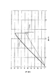
図7は、2種類のベルトに引張荷重を加えた場合における荷重と歪との関係を示すグラフである。図7において、実線はベルトbを示し、破線はベルトaを示す。 FIG. 7 is a graph showing the relationship between load and strain when a tensile load is applied to two types of belts. In FIG. 7, a solid line indicates the belt b, and a broken line indicates the belt a.
ここで、ベルトaに配設されたスチールコードは、1本のシースフィラメントの直径が0.225mmであり、このシースフィラメントを円周状に5本配置して撚った単撚りの1×5構造のスチールコードである。該スチールコードを50mmの幅の中に36本打ち込んでベルトaが得られる。 Here, the steel cord disposed on the belt a has a diameter of one sheath filament of 0.225 mm, and a single twist of 1 × 5 is twisted by arranging five sheath filaments circumferentially. Steel cord with structure. 36 belts a are obtained by driving 36 steel cords into a width of 50 mm.
また、ベルトbに配設されたスチールコードは、中央側に1本のコアフィラメントが配置され、該コアフィラメントの周囲に円周状に6本のシースフィラメントが配置された単撚りの1+6構造のスチールコードであり、コアフィラメントおよびシースフィラメントの直径は0.24mmである。該スチールコードを50mmの幅の中に22本打ち込んでベルトbが得られる。 Further, the steel cord disposed on the belt b has a single twist 1 + 6 structure in which one core filament is disposed at the center side, and six sheath filaments are disposed circumferentially around the core filament. It is a steel cord, and the diameter of the core filament and the sheath filament is 0.24 mm. The belt b is obtained by driving 22 steel cords into a width of 50 mm.
これらのベルトa,bを軸方向に引っ張ったときの引張荷重と歪との関係が図7のグラフに示されている。同一荷重を加えた場合に、実線のベルトbの歪は、破線のベルトaよりも歪量が小さい。これは、ベルトbの方がベルトaよりも引張強度が大きいことを意味している。 The relationship between tensile load and strain when these belts a and b are pulled in the axial direction is shown in the graph of FIG. When the same load is applied, the distortion of the solid belt b is smaller than that of the broken belt a. This means that the belt b has a higher tensile strength than the belt a.
本発明では、第1ベルトとして例えばベルトaを適用し、第2ベルトとして例えばベルトbを適用することができる。 In the present invention, for example, the belt a can be applied as the first belt, and the belt b can be applied as the second belt.
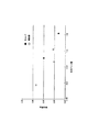
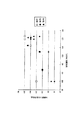
また、図8は実施例2における接地面積と氷路面上の走行性能との関係を示すグラフである。このグラフにおいて、系列1は−8℃の路面を走行した場合を示し、系列2は0℃の路面を走行した場合を示し、系列3は0℃以下の路面を走行した場合を示す。
FIG. 8 is a graph showing the relationship between the ground contact area and the running performance on the icy road surface in Example 2. In this graph, Series 1 shows a case where the vehicle travels on a road surface of −8 ° C.,
このように、第2ベルトのスチールコードの引張強度を第2ベルトのスチールコードの引張強度よりも大きくすることによって、車両の氷路面上の走行性能を高めることができることが判明した。 Thus, it has been found that the running performance on the icy road surface of the vehicle can be improved by making the tensile strength of the steel cord of the second belt larger than the tensile strength of the steel cord of the second belt.
1 空気入りタイヤ
3 カーカス
4 ベルト層
5 トレッド部
6 サイドウォール部
9 ビード部
10 第1ベルト
10a,11a 幅方向端縁
11 第2ベルト
21,22 スチールコード
DESCRIPTION OF SYMBOLS 1
Claims (4)
前記ベルト層は、前記カーカスの頂部のタイヤ径方向外側に配置された第1ベルトと、前記第1ベルトのタイヤ径方向外側に配置され、タイヤ幅方向に沿った幅寸法が前記第1ベルトよりも小さく形成された第2ベルトとからなり、
前記第2ベルトのタイヤ幅方向両側における幅方向端縁は、前記第1ベルトの幅方向端縁からタイヤ幅方向内側に向けて10〜15mmの範囲に位置していることを特徴とする空気入りタイヤ。 A pair of bead portions spaced apart in the tire width direction; a carcass that connects the pair of bead portions in a crown shape; a belt layer disposed on the outer side in the tire radial direction of the top of the carcass; and the carcass A pneumatic tire provided with a tread portion and a sidewall portion arranged to cover
The belt layer is disposed on the outer side in the tire radial direction of the top of the carcass, and is disposed on the outer side in the tire radial direction of the first belt, and the width dimension along the tire width direction is greater than that of the first belt. And the second belt formed to be small,
The pneumatic belt characterized in that the widthwise edges on both sides of the second belt in the tire width direction are located within a range of 10 to 15 mm from the widthwise edge of the first belt toward the inside in the tire width direction. tire.
前記第2ベルトに設けられたスチールコードの引張強度は、前記第1ベルトに設けられたスチールコードの引張強度よりも大きい値に設定されたことを特徴とする請求項1に記載の空気入りタイヤ。 Each of the first belt and the second belt is provided with a plurality of steel cords,
2. The pneumatic tire according to claim 1, wherein the tensile strength of the steel cord provided on the second belt is set to a value larger than the tensile strength of the steel cord provided on the first belt. .
Priority Applications (1)
| Application Number | Priority Date | Filing Date | Title |
|---|---|---|---|
| JP2008322058A JP2010143369A (en) | 2008-12-18 | 2008-12-18 | Pneumatic tire |
Applications Claiming Priority (1)
| Application Number | Priority Date | Filing Date | Title |
|---|---|---|---|
| JP2008322058A JP2010143369A (en) | 2008-12-18 | 2008-12-18 | Pneumatic tire |
Publications (1)
| Publication Number | Publication Date |
|---|---|
| JP2010143369A true JP2010143369A (en) | 2010-07-01 |
Family
ID=42564252
Family Applications (1)
| Application Number | Title | Priority Date | Filing Date |
|---|---|---|---|
| JP2008322058A Pending JP2010143369A (en) | 2008-12-18 | 2008-12-18 | Pneumatic tire |
Country Status (1)
| Country | Link |
|---|---|
| JP (1) | JP2010143369A (en) |
Citations (6)
| Publication number | Priority date | Publication date | Assignee | Title |
|---|---|---|---|---|
| JPS51122202A (en) * | 1975-04-07 | 1976-10-26 | Firestone Tire & Rubber Co | Pneumatic tire |
| JPH03169716A (en) * | 1989-11-30 | 1991-07-23 | Sumitomo Rubber Ind Ltd | Radial tire |
| JPH06270608A (en) * | 1993-03-22 | 1994-09-27 | Sumitomo Rubber Ind Ltd | Pneumatic tire |
| JPH07329508A (en) * | 1994-06-14 | 1995-12-19 | Sumitomo Rubber Ind Ltd | Pneumatic tire |
| JP2008105667A (en) * | 2006-09-29 | 2008-05-08 | Bridgestone Corp | Pneumatic radial tire |
| JP2008143347A (en) * | 2006-12-08 | 2008-06-26 | Bridgestone Corp | Pneumatic tire |
-
2008
- 2008-12-18 JP JP2008322058A patent/JP2010143369A/en active Pending
Patent Citations (6)
| Publication number | Priority date | Publication date | Assignee | Title |
|---|---|---|---|---|
| JPS51122202A (en) * | 1975-04-07 | 1976-10-26 | Firestone Tire & Rubber Co | Pneumatic tire |
| JPH03169716A (en) * | 1989-11-30 | 1991-07-23 | Sumitomo Rubber Ind Ltd | Radial tire |
| JPH06270608A (en) * | 1993-03-22 | 1994-09-27 | Sumitomo Rubber Ind Ltd | Pneumatic tire |
| JPH07329508A (en) * | 1994-06-14 | 1995-12-19 | Sumitomo Rubber Ind Ltd | Pneumatic tire |
| JP2008105667A (en) * | 2006-09-29 | 2008-05-08 | Bridgestone Corp | Pneumatic radial tire |
| JP2008143347A (en) * | 2006-12-08 | 2008-06-26 | Bridgestone Corp | Pneumatic tire |
Similar Documents
| Publication | Publication Date | Title |
|---|---|---|
| JP6214490B2 (en) | Pneumatic tire | |
| US10105992B2 (en) | Pneumatic tire | |
| JP6467949B2 (en) | Pneumatic tire | |
| JP2009214760A (en) | Pneumatic tire for heavy load | |
| JP2014184808A (en) | Pneumatic tire | |
| JP6665561B2 (en) | Pneumatic tire | |
| CN112770919B (en) | Pneumatic tire | |
| WO2015159538A1 (en) | Pneumatic tire | |
| KR20130112763A (en) | Pneumatic tire | |
| CN106414114A (en) | Vehicle tyres | |
| JP2018095042A (en) | Pneumatic tire | |
| JP2017121888A (en) | Pneumatic tire | |
| CN105682940B (en) | Tire | |
| JP2012071791A (en) | Pneumatic tire | |
| JP5308781B2 (en) | Pneumatic tire | |
| WO2015156154A1 (en) | Tire | |
| JP6040039B2 (en) | Tires for motorcycles | |
| JP6087571B2 (en) | Pneumatic tire | |
| CN110843425B (en) | Pneumatic tire | |
| JP2010143369A (en) | Pneumatic tire | |
| JP4634888B2 (en) | Pneumatic tire | |
| JP2017185984A (en) | Pneumatic tire | |
| JP2008149986A (en) | Pneumatic tire | |
| JP2008149904A (en) | Pneumatic tire | |
| JP2009154685A (en) | Tire |
Legal Events
| Date | Code | Title | Description |
|---|---|---|---|
| A621 | Written request for application examination |
Free format text: JAPANESE INTERMEDIATE CODE: A621 Effective date: 20111214 |
|
| A131 | Notification of reasons for refusal |
Free format text: JAPANESE INTERMEDIATE CODE: A131 Effective date: 20130122 |
|
| A977 | Report on retrieval |
Free format text: JAPANESE INTERMEDIATE CODE: A971007 Effective date: 20130123 |
|
| A521 | Written amendment |
Free format text: JAPANESE INTERMEDIATE CODE: A523 Effective date: 20130322 |
|
| A02 | Decision of refusal |
Free format text: JAPANESE INTERMEDIATE CODE: A02 Effective date: 20130813 |