JP2010143101A - Wiping device of letterpress machine - Google Patents
Wiping device of letterpress machine Download PDFInfo
- Publication number
- JP2010143101A JP2010143101A JP2008323332A JP2008323332A JP2010143101A JP 2010143101 A JP2010143101 A JP 2010143101A JP 2008323332 A JP2008323332 A JP 2008323332A JP 2008323332 A JP2008323332 A JP 2008323332A JP 2010143101 A JP2010143101 A JP 2010143101A
- Authority
- JP
- Japan
- Prior art keywords
- cleaning
- wiping
- wiping roller
- roller
- intaglio printing
- Prior art date
- Legal status (The legal status is an assumption and is not a legal conclusion. Google has not performed a legal analysis and makes no representation as to the accuracy of the status listed.)
- Pending
Links
Images


Landscapes
- Rotary Presses (AREA)
- Inking, Control Or Cleaning Of Printing Machines (AREA)
Abstract
【課題】 凹版印刷機のワイピング装置として、ワイピングローラ表面に残存する余剰インキを迅速かつ確実に除去するとともに、長時間にわたって良好な印刷物を得ることと高速印刷を可能とし、併せてオペレータの負担軽減を図る。
【解決手段】 ワイピングローラと接触しローラ表面の余剰インキを除去する複数の洗浄粒子と、自重沈殿にて降下した洗浄粒子を載置する洗浄粒子載置用部材と、洗浄粒子載置用部材の下部に配置され、洗浄粒子をワイピングローラに指向し投射させる吐出圧供給装置とから構成される洗浄機構を少なくとも1組以上備えている凹版印刷機のワイピング装置とした。
【選択図】 図1PROBLEM TO BE SOLVED: To quickly and surely remove excess ink remaining on a surface of a wiping roller as a wiping device of an intaglio printing press, to obtain a good printed matter for a long time and to enable high-speed printing, and to reduce an operator's burden. Plan.
SOLUTION: A plurality of cleaning particles that come into contact with a wiping roller to remove excess ink on a roller surface, a cleaning particle mounting member for mounting cleaning particles lowered by its own weight precipitation, and a cleaning particle mounting member A wiping device for an intaglio printing press provided with at least one cleaning mechanism, which is arranged at the lower part and includes a discharge pressure supply device that directs and projects cleaning particles toward the wiping roller.
[Selection] Figure 1
Description
本発明は、凹版印刷機のワイピングローラを洗浄するワイピング装置に関するものである。 The present invention relates to a wiping device for cleaning a wiping roller of an intaglio printing press.
一般に、凹版印刷機のワイピング装置は、図10に示すように凹版胴(8)に装着された凹版版面上の余剰なインキを拭き取る樹脂製のワイピングローラ(7)と、このワイピングローラ(7)上に付着したインキを溶解及び分散させるための洗浄液(15)を満たした浸漬型洗浄槽と称されるワイピング槽(6)と、このワイピングローラ(7)に接触して機械的にインキを取り除く機能を有する複数個のブラシ群(4)から構成される洗浄部材及び/又はこのブラシ群(4)の上にインキの抜けを阻害しない開き目を有し、かつ柔軟性がある合成繊維製のタワシ(5)を載せてワイピングローラ(7)と面接触させる支軸(2)に固定された洗浄部材(3)と、この洗浄部材(3)の下流側に位置してワイピングローラ(7)の表面上に残存する洗浄液(15)を拭き取る鋼製又は樹脂製の仕上げブレード(9)から構成され、図示しない印刷部にて用紙に印刷が施される。 In general, a wiping device for an intaglio printing machine includes a resin wiping roller (7) for wiping off excess ink on an intaglio plate surface mounted on an intaglio cylinder (8) and a wiping roller (7) as shown in FIG. A wiping tank (6) called an immersion type cleaning tank filled with a cleaning liquid (15) for dissolving and dispersing the ink adhering to the ink, and the ink is mechanically removed by contact with the wiping roller (7). Made of a synthetic fiber having a cleaning member composed of a plurality of brush groups (4) having a function and / or an opening on the brush group (4) that does not impair ink removal and is flexible. A cleaning member (3) fixed on a support shaft (2) on which a scrubber (5) is placed and brought into surface contact with the wiping roller (7), and a wiping roller (7) positioned downstream of the cleaning member (3) On the surface of Exists is composed of a steel or made of a resin finishing blades wipe a cleaning liquid (15) (9), printed on the paper is performed by the printing section (not shown).
従来の浸漬型ワイピング装置では、枚葉紙9,000枚/時間未満の印刷速度において、洗浄液あるいは洗浄部材とワイピングローラが接触する時間が長く、ワイピングローラ表面に付着したインキを完全に溶解及び分散させることができる。また、インキを溶解及び分散させた後にローラ表面に残存する薄い洗浄液の薄膜層も仕上げブレードにより取り除かれ、完全に清浄化されたワイピングローラが再び凹版版面上のインキを拭き取るためのサイクルに入ることで、汚れのない凹版印刷物を連続的に印刷することが可能であった。 In the conventional immersion type wiping device, at a printing speed of less than 9,000 sheets / hour, the cleaning liquid or the cleaning member and the wiping roller are in contact with each other for a long time, and the ink adhering to the surface of the wiping roller is completely dissolved and dispersed. Can be made. Also, the thin film layer of the thin cleaning liquid remaining on the roller surface after the ink is dissolved and dispersed is removed by the finishing blade, and the completely cleaned wiping roller enters the cycle for wiping off the ink on the intaglio plate again. Thus, it was possible to continuously print intaglio prints without stains.
しかしながら、上述したような従来のワイピング装置にあっては、洗浄液が新しい状態においては拭き取られたインキが効率的に洗浄液中に溶解及び分散するが、印刷時間の経過とともに洗浄液中のインキ濃度が高くなり、このためにインキの溶解及び分散能力が低下し、洗浄部材の上部に位置する合成繊維性のタワシに未溶解のインキが徐々に蓄積されるようになる。そのため、連続印刷枚数が枚葉紙で約5万枚以上に達すると、ワイピングローラ上のインキが完全に拭き取れず、僅かに残ったインキが印刷物に付着する「拭き残り」と称する印刷欠陥や、汚れた洗浄液が印刷物に付着する「溶剤汚れ」と称する印刷欠陥が生じていた。このような事象が生じた場合、オペレータは印刷機械を一旦停止させ、洗浄部材を洗浄したり、洗浄液を交換する等の措置を講じる必要があり、不稼働時間が増加したり、また、この洗浄作業がオペレータにとって作業服や手が汚れる好ましくない作業であるという問題があった。 However, in the conventional wiping apparatus as described above, when the cleaning liquid is new, the wiped ink is efficiently dissolved and dispersed in the cleaning liquid. However, as the printing time elapses, the ink concentration in the cleaning liquid increases. As a result, the ability to dissolve and disperse the ink decreases, and undissolved ink gradually accumulates in the synthetic fibrous scrubber located above the cleaning member. Therefore, when the number of continuous prints reaches about 50,000 sheets or more with a sheet of paper, the ink on the wiping roller cannot be completely wiped off, and a printing defect called “wiping residue” in which a slight amount of remaining ink adheres to the printed matter, There was a printing defect called “solvent stain” in which the dirty cleaning liquid adheres to the printed matter. When such an event occurs, the operator must stop the printing machine and take measures such as cleaning the cleaning member or replacing the cleaning liquid. There has been a problem that the work is an unfavorable work for the operator to contaminate work clothes and hands.
一方、枚葉紙9,000枚/時間以上の高速印刷になると、ワイピング槽に満たした洗浄液がワイピングローラの増速により、ワイピングローラ上に厚い洗浄膜厚層を形成し、下流に位置する仕上げブレードに衝撃となって現われ、この仕上げブレードを強く押し上げるため、ワイピングローラと仕上げブレードとの間に極僅かな隙間が生じて洗浄液を完全に除去できない現象が生じる。この現象は「液上がり現象」と称しているが、ワイピングローラ表面に洗浄液を残したまま次の版面の洗浄サイクルに入ることから、凹版版面内のインキを溶解して印刷物をにじませたり、印刷用紙に洗浄液が付着したりするなど印刷物の品質を著しく損ねることから、凹版印刷機の高速化を阻害するという問題があった。 On the other hand, when high-speed printing is performed at 9,000 sheets / hour or more, the cleaning liquid filled in the wiping tank forms a thick cleaning film thickness layer on the wiping roller due to the accelerating speed of the wiping roller, and the finish located downstream An impact appears on the blade, and this finishing blade is pushed up strongly, so that a very slight gap is formed between the wiping roller and the finishing blade, and the cleaning liquid cannot be completely removed. This phenomenon is called "liquid rising phenomenon", but since it enters the next plate surface cleaning cycle with the cleaning liquid remaining on the surface of the wiping roller, the ink in the intaglio plate surface is dissolved to smear the printed matter, There has been a problem that the speed of the intaglio printing machine is hindered because the quality of the printed matter is remarkably impaired, for example, the cleaning liquid adheres to the printing paper.
この問題点を解消する方策として、凹版印刷機のワイピング部において、洗浄部材上のインキ堆積を抑制するとともに、長時間にわたって良好な印刷物を得ることと高速印刷を可能とし、併せてオペレータの負担軽減を図るため、ワイピングローラ表面に付着したインキを洗浄する装置の洗浄機構がある。この洗浄装置として、機械的にインキを取り除く洗浄部材と洗浄部材の下部に置いたインキを溶解及び分散させるための洗浄液を噴射する装置とが一体となって構成される第1段の洗浄部材と、ワイピングローラ上に残存する洗浄液を機械的に取り除く第2段の洗浄液回収装置を第1段の洗浄部材の下流側に設けた凹版印刷機のワイピング装置がある(例えば、特許文献1参照)。 In order to solve this problem, in the wiping section of the intaglio printing press, while suppressing ink accumulation on the cleaning member, it is possible to obtain a good printed material for a long time and to perform high-speed printing, and to reduce the burden on the operator. Therefore, there is a cleaning mechanism of a device for cleaning ink adhering to the surface of the wiping roller. As the cleaning device, a first-stage cleaning member configured integrally with a cleaning member for removing ink mechanically and a device for spraying a cleaning liquid for dissolving and dispersing ink placed under the cleaning member; There is a wiping device for an intaglio printing machine in which a second-stage cleaning liquid recovery device that mechanically removes the cleaning liquid remaining on the wiping roller is provided on the downstream side of the first-stage cleaning member (see, for example, Patent Document 1).
また、凹版印刷機のワイピング部において、中間噴射装置及びワイピング槽下部洗浄噴射装置を新たに設け、既存の噴射装置である噴射装置付きプレブラシ及び噴射装置付きメインブラシと、新たに設置した中間噴射装置及びワイピング槽下部洗浄噴射装置から洗浄水を噴射することによって、ワイピング槽を印刷機械に固定した状態でワイピング槽、ワイピングローラ、噴射装置付きプレブラシ、噴射装置付きメインブラシ及び各溶液配管内の洗浄を同時に行う装置及び方法がある(例えば、特許文献2参照)。 In addition, in the wiping section of the intaglio printing press, an intermediate injection device and a wiping tank lower cleaning injection device are newly provided, and the existing pre-brush with the injection device and the main brush with the injection device, and the newly installed intermediate injection device And cleaning the inside of each solution pipe with the wiping tank, the wiping roller, the pre-brush with the spraying device, the main brush with the spraying device, with the wiping bath fixed to the printing machine There is an apparatus and a method that perform simultaneously (see, for example, Patent Document 2).
上述した先行技術である特許文献1の技術を用いた場合、ワイピングローラで拭き取られたインキは、噴射洗浄液によって溶解及び分散され、この洗浄液を回収、再循環、再噴射のサイクルを繰り返すことにより、第1段の洗浄部材がワイピングローラと接触する部位における未溶解インキの蓄積を抑制することができる。また、第1段の洗浄部材の下流にワイピングローラに残存する膜状の洗浄液を効果的に取り除く第2段の洗浄液回収装置を設けたことにより、ワイピングローラ上の洗浄液を取り除くことが可能となる。
In the case of using the technology of
さらに、枚葉紙9,000枚/時間以上の高速印刷時であっても、ワイピングローラ上に形成される洗浄液の皮膜層が薄いため、下流に位置する仕上げブレードに衝撃を与えにくく、ワイピングローラと仕上げブレードとの接触を低速時と同様の状態に保つことが可能となる。これらの手段を講じても、ワイピングローラが凹版版面との間で起こる押圧力にて摩耗し、このために生じる第1段の洗浄部材との微妙な隙間がインキの蓄積を許し、印刷物に汚れが発生することがあるが、このような場合でも印刷機械を停止させることなく用紙の供給のみを停止して、噴射洗浄装置による自浄作用で洗浄部材を洗浄することが可能になり、従来の浸漬型ワイピング装置と異なり、「溶剤汚れ」及び「液上がり現象」がなくなり、良好な印刷物を安定して生産することが可能となる。 Furthermore, even during high-speed printing at 9,000 sheets / hour or more, since the coating layer of the cleaning liquid formed on the wiping roller is thin, it is difficult to give impact to the finishing blade located downstream, and the wiping roller And the finish blade can be kept in the same state as at low speed. Even if these measures are taken, the wiping roller is worn by the pressing force generated between the intaglio plate surface, and the fine gap with the first-stage cleaning member that occurs for this reason allows the accumulation of ink, resulting in stains on the printed matter. However, even in such a case, it is possible to stop only the paper supply without stopping the printing machine, and to clean the cleaning member by the self-cleaning action by the jet cleaning device. Unlike the mold wiping apparatus, “solvent stain” and “liquid rising phenomenon” are eliminated, and a good printed product can be stably produced.
しかしながら、特許文献1の技術は、ある程度タワシへの未溶解インキの蓄積を抑制することが可能であるが、洗浄部材がワイピングローラ表面と接触した状態で洗浄部材の下部に配置した噴射装置から洗浄液を噴射させ、タワシ表面のインキを除去させる洗浄仕組であることから、タワシ上の未溶解インキを全領域に亘って完全に除去することはできず、徐々にインキが堆積することになり、やがて洗浄不良等の不具合が生じることになる。これらを勘案すると、近年主流となっている高速印刷(枚葉紙12,000枚/時間)を実施した場合、印刷速度に対応することができない場合もあり、良質な印刷製品を連続的に生産することが困難となる。
However, although the technique of
また、特許文献2の技術を用いた場合、中間噴射装置を噴射装置付きプレブラシと噴射装置付きメインブラシとの間に設置することによって、洗浄液を噴射装置付きメインブラシにまで送流することができ、過剰なインキやインキ滓が噴射装置付きメインブラシに送られることが抑制できる。このことで、噴射装置付きメインブラシの延命使用が可能となる。また、ワイピングローラ、ワイピング槽、洗浄部材並びに仕上げ洗浄部材を取り外して洗浄するといった人手の介在が無くなるため、これらの部材等を再度取り付ける際に懸念されるワイピングローラへの損傷が無くなり、時間浪費の改善及び材料にかかるコスト低減が図れ有用である。
Further, when the technique of
しかしながら、特許文献2の技術は、噴射装置付きプレブラシ及び噴射装置付きメインブラシへのインキ堆積が大幅に抑制できるもののインキ堆積が皆無になることはなく、時間の経過とともにそれぞれのブラシへインキ滓が堆積することになる。また、それぞれのブラシは、回動するワイピングローラと接触していることから、摩滅損耗することが避けられない。このブラシの交換頻度を遅らせると、場合によっては、ワイピングローラ表面上に存するインキの拭き取りが十分でなくなり、「溶剤汚れ」及び「液上がり現象」といった印刷欠陥が発生する場合があり、所望する高品質な印刷製品を得ることができない。この対策として、ブラシ等の洗浄部材を定期的に洗浄又は交換しなければならず、オペレータにとって作業手間が増大するばかりでなく、かかるコストが増加する。これらの理由により必ずしも先行技術に移行しない現状がある。現時点において、上述した問題点への対策が施されておらず、少なからず改善の余地があった。
However, although the technique of
上記のような課題を解決するため、本発明の凹版印刷機のワイピング装置は、凹版印刷機のワイピング部において、ワイピングローラ表面に付着した余剰インキを洗浄する装置として、ワイピングローラと接触しローラ表面の余剰インキを除去する複数の洗浄粒子と、自重沈殿にて降下した洗浄粒子を載置する洗浄粒子載置用部材と、洗浄粒子載置用部材の下部に配置され、洗浄粒子をワイピングローラに指向し投射させる吐出圧供給装置とから構成される洗浄機構を少なくとも1組以上備えていることを特徴とする。 In order to solve the above-described problems, the wiping device for an intaglio printing press according to the present invention is a device that comes into contact with the wiping roller as a device for cleaning excess ink adhering to the surface of the wiping roller in the wiping portion of the intaglio printing press. A plurality of cleaning particles for removing the excess ink, a cleaning particle mounting member for mounting the cleaning particles lowered by the self-weight precipitation, and a cleaning particle mounting member disposed below the cleaning particle mounting member. It is characterized by comprising at least one cleaning mechanism comprising a discharge pressure supply device that directs and projects.
また、本発明の凹版印刷機のワイピング装置は、洗浄機構に対して、ワイピングローラ回転方向下流側に、ワイピングローラ上に残存する余剰インキを機械的に取り除く吸引装置を備えていることを特徴とする。 Further, the wiping device of the intaglio printing press according to the present invention includes a suction device that mechanically removes excess ink remaining on the wiping roller on the downstream side in the rotation direction of the wiping roller with respect to the cleaning mechanism. To do.
また、本発明の凹版印刷機のワイピング装置は、洗浄機構に対して、ワイピングローラ回転方向下流側に、ワイピングローラ上に残存する余剰インキを機械的に取り除く、複数列のブラシ群の上にインキの抜けを阻害しない開き目を有し、かつ柔軟性がある合成繊維製不織布又は樹脂を載せ、ワイピングローラと面接触する機能を有する洗浄補助機構を備えていることを特徴とする。 Further, the wiping device of the intaglio printing press according to the present invention is configured to remove the ink remaining on the wiping roller mechanically on the downstream side in the rotation direction of the wiping roller with respect to the cleaning mechanism. It is characterized by having a cleaning auxiliary mechanism that has a function of contacting the surface of the wiping roller with a synthetic fiber non-woven fabric or resin that has an opening that does not impede omission and is flexible.
また、本発明の凹版印刷機のワイピング装置における洗浄粒子載置用部材の形状は、格子状メッシュ又はスルーホールであることを特徴とする。 In addition, the shape of the cleaning particle mounting member in the wiping device of the intaglio printing press according to the present invention is a lattice mesh or a through hole.
また、本発明の凹版印刷機のワイピング装置における吐出圧供給装置は、溶剤、水、油、空気から選択される成分のいずれかにより洗浄粒子をワイピングローラに指向し投射することを特徴とする。 Further, the discharge pressure supply device in the wiping device of the intaglio printing press according to the present invention is characterized in that the cleaning particles are directed and projected to the wiping roller by any one of components selected from a solvent, water, oil and air.
また、本発明の凹版印刷機のワイピング装置における洗浄粒子は、金属、樹脂又はゴムのいずれかの材質から形成されており、表面形状を多面体としていることを特徴とする。 In addition, the cleaning particles in the wiping device of the intaglio printing press according to the present invention are made of any material of metal, resin, or rubber, and have a polyhedron surface shape.
さらに、本発明の凹版印刷機のワイピング装置における洗浄機構は、ワイピング槽に洗浄液を満たした浸漬型ワイピング装置に用いていることを特徴とする。 Further, the cleaning mechanism in the wiping device of the intaglio printing press according to the present invention is used in an immersion type wiping device in which a wiping tank is filled with a cleaning liquid.
本発明の凹版印刷機のワイピング装置は、洗浄液中において洗浄粒子をワイピングローラに指向し投射する機構であることから、常時洗浄部材をワイピングローラに接触させていた従前技術とは異なり、洗浄部材へのインキ堆積による洗浄不良の発生がなくなる。また、洗浄部材をワイピングローラに接触し続けた場合に誘発されるワイピングローラの熱膨張及びワイピングローラの表面硬度の軟化による顕著な摩滅損耗を気にすることなく洗浄できるとともに、ワイピングローラ表面に存するインキ滓等を適宜効果的に除去できることから、均質な製品を長期間において連続的かつ安定的に得ることが可能となるといった充実した製品品質が保全できるという効果を奏する。 Since the wiping device of the intaglio printing press according to the present invention is a mechanism that directs and projects the cleaning particles to the wiping roller in the cleaning liquid, unlike the conventional technology in which the cleaning member is always in contact with the wiping roller, Occurrence of poor cleaning due to ink accumulation is eliminated. Further, the cleaning member can be cleaned without worrying about remarkable wear and wear due to thermal expansion of the wiping roller and softening of the surface hardness of the wiping roller induced when the cleaning member is kept in contact with the wiping roller. Since ink fountains and the like can be effectively removed as appropriate, there is an effect that a complete product quality can be maintained such that a homogeneous product can be obtained continuously and stably over a long period of time.
また、本発明の凹版印刷機のワイピング装置は、ワイピングローラ表面に存するインキ滓等を除去する手段として、ワイピングローラへ洗浄粒子を接触させることでなされることから、ワイピングローラへの洗浄媒体の接触時間を最小限に設計できる。このことで、従前まで懸念されていたワイピングローラへのインキ滓等の浸透が大幅に規制できるとともに、過剰な洗浄部材の接触によって誘発されるローラの軟化による局所的磨耗が抑制できる。その結果、ワイピングローラは延命使用することが可能となり、交換頻度の大幅な削減、ワイピングローラの焼成、研磨等にかかる負担の低減、従前まで多々使用していたタワシ等の消耗品の削減が実現でき、従前に比して大幅なコスト低減が図れるという効果を奏する。 Further, the wiping device of the intaglio printing press according to the present invention is made by bringing cleaning particles into contact with the wiping roller as means for removing ink fountain etc. existing on the surface of the wiping roller. Design time to a minimum. As a result, the penetration of ink fountain and the like into the wiping roller, which has been a concern in the past, can be greatly restricted, and local wear due to softening of the roller induced by contact with an excessive cleaning member can be suppressed. As a result, it is possible to extend the life of the wiping roller, greatly reducing the replacement frequency, reducing the burden on firing and polishing of the wiping roller, and reducing consumables such as scrubber that have been used many times before. This is advantageous in that the cost can be greatly reduced as compared with the prior art.
また、本発明の凹版印刷機のワイピング装置は、洗浄媒体としての洗浄粒子が繰り返し使用できることから、これまでインキや溶剤を含み産業廃棄物として処理していたタワシ等の消耗品が発生しなくなるといった環境特性における改善が図れるという効果を奏する。 In addition, the wiping device of the intaglio printing press according to the present invention can repeatedly use cleaning particles as a cleaning medium, so that consumables such as scrubbing that have been treated as industrial waste up to now include ink and solvent are not generated. There is an effect that the environmental characteristics can be improved.
さらに、本発明の凹版印刷機のワイピング装置を用いることで、ワイピングローラの十分な洗浄が可能となるとともに、この課題における印刷機械の高速化が制限されなくてよくなり、加えて、ワイピングローラの延命化に寄与できることから、作業負荷の低減が図れる。また、ワイピングローラの交換等に付随する作業手間が少なくて済み、従前までオペレータにより行われていた各種調整作業が減少することによる作業性の大幅な改善及び印刷機械の不稼働時間が低減できるという効果を奏する。 Further, by using the wiping device of the intaglio printing press according to the present invention, it is possible to sufficiently clean the wiping roller, and it is not necessary to limit the speeding up of the printing machine in this problem. Since it can contribute to prolonging the life, the workload can be reduced. In addition, the labor associated with the replacement of the wiping roller can be reduced, and various adjustment operations previously performed by the operator can be reduced, thereby greatly improving workability and reducing the downtime of the printing machine. There is an effect.
図1乃至図10に基づき、この発明の実施形態を説明する。図1は本発明における凹版印刷機のワイピング装置の概略図であり、図2乃至図4は別形態のワイピング装置の概略図である。また、図5及び図6は洗浄粒子の形態の一例を示す概略図であり、図7は洗浄粒子載置用部材の一例を示す図である。さらに、図8乃至図10は一般的な凹版印刷機のワイピング装置の概略図である。 An embodiment of the present invention will be described with reference to FIGS. FIG. 1 is a schematic view of a wiping device of an intaglio printing press according to the present invention, and FIGS. 2 to 4 are schematic views of another type of wiping device. 5 and 6 are schematic views showing an example of the form of the cleaning particles, and FIG. 7 is a view showing an example of the cleaning particle mounting member. Further, FIGS. 8 to 10 are schematic views of a general intaglio printing machine wiping apparatus.
まず、一般的な凹版印刷機におけるワイピング装置について説明する。図10に示す一般的な凹版印刷機は、凹版胴(8)に装着した図示しない凹版版面へ付着した余剰インキの除去を行うワイピングローラ(7)の洗浄機構として、支軸(2)に固定された洗浄部材(3)に複数本のナイロン製のブラシ(4)を埋め込み、該ブラシ(4)の上部に合成繊維製不織布(例えば、タワシ)(5)が存する態様である。ここで、ワイピングローラ(7)は、洗浄液(15)を満たしたワイピング槽(6)に懸架されており、凹版版面から拭き取った余剰インキをワイピングローラ(7)に対して一定圧力にて押圧して接触させたタワシ(5)により除去し、下流に配した仕上げブレード(9)により残留した洗浄液(15)を掻き落とし、ワイピングローラ(7)を完全に洗浄して、次回の凹版版面の洗浄に備えるものである。 First, a wiping device in a general intaglio printing press will be described. The general intaglio printing machine shown in FIG. 10 is fixed to a support shaft (2) as a cleaning mechanism for a wiping roller (7) that removes excess ink adhering to an intaglio plate surface (not shown) mounted on an intaglio cylinder (8). A plurality of nylon brushes (4) are embedded in the washed member (3), and a synthetic fiber nonwoven fabric (for example, scrubbing) (5) is present on the upper part of the brush (4). Here, the wiping roller (7) is suspended in a wiping tank (6) filled with the cleaning liquid (15), and presses excess ink wiped off from the intaglio plate surface against the wiping roller (7) at a constant pressure. The cleaning liquid (15) removed by the finishing blade (9) disposed downstream is scraped off by the scrubbing brush (5) that has been brought into contact with it, and the wiping roller (7) is thoroughly cleaned to clean the next intaglio plate surface. To prepare for.
また、図8に示す一般的な凹版印刷機のワイピング装置は、ワイピング槽(6)に洗浄液(15)を滞留させず、図示しない洗浄液供給機構からの洗浄液(15)を支軸(2)に固定された洗浄部材(3)に配置した噴射装置(12)の噴射ノズル(13)から一定の吐出圧を有する洗浄液(15)をワイピングローラ(7)との間に配置したタワシ(5)を介して供給する機構であり、その下流にはインキ滓成分を含む洗浄液(15)を吸引及び回収する吸引装置(10)、さらにその下流には補助ブレード(11)、最下流には仕上げブレード(9)をそれぞれ配置している態様である。また、図9に示す一般的な凹版印刷機のワイピング装置は、2箇所配置された洗浄部材(3)の間に中間噴射装置(14)を配置している態様である。 Further, in the general intaglio printing machine wiping device shown in FIG. 8, the cleaning liquid (15) does not stay in the wiping tank (6), and the cleaning liquid (15) from the cleaning liquid supply mechanism (not shown) is used as the support shaft (2). A scrubber (5) in which a cleaning liquid (15) having a constant discharge pressure is disposed between the wiping roller (7) from the spray nozzle (13) of the spray device (12) disposed in the fixed cleaning member (3). A suction device (10) that sucks and collects the cleaning liquid (15) containing the ink fountain component downstream, an auxiliary blade (11) downstream, and a finishing blade ( 9). Moreover, the wiping apparatus of the general intaglio printing machine shown in FIG. 9 is the aspect which has arrange | positioned the intermediate | middle injection apparatus (14) between the washing | cleaning members (3) arrange | positioned at two places.
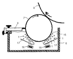
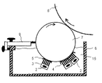
一方、図1に示すように本発明の凹版印刷機のワイピング装置は、凹版胴(8)に装着された図示しない凹版版面から拭き取り、ワイピングローラ(7)の表面に存する余剰インキの洗浄手段として、洗浄液(15)を滞留させたワイピング槽(6)の内部に存し、ワイピングローラ(7)に対して、適宜、接触又は離間する複数個の洗浄粒子(1)と、洗浄粒子(1)をワイピングローラ(7)に指向し投射させる支軸(2)に固定された吐出圧供給装置(16)と、自重沈殿にて降下した洗浄粒子(1)を載置する支軸(2)に固定された洗浄粒子載置用部材(17)とから形成される洗浄機構を少なくとも1組以上備えた態様であり、そのローラ回転方向の下流には、ワイピングローラ(7)の表面を完全に洗浄する仕上げブレード(9)を配置している態様である。 On the other hand, as shown in FIG. 1, the wiping device of the intaglio printing press according to the present invention wipes from an intaglio plate surface (not shown) mounted on the intaglio cylinder (8) and serves as a means for cleaning excess ink existing on the surface of the wiping roller (7). A plurality of cleaning particles (1), which are present in the wiping tank (6) in which the cleaning liquid (15) is retained and which are appropriately brought into contact with or separated from the wiping roller (7), and the cleaning particles (1) On the support shaft (2) fixed to the support shaft (2) for directing and projecting to the wiping roller (7), and the support shaft (2) on which the cleaning particles (1) lowered by the self-weight precipitation are placed. It is an aspect provided with at least one or more cleaning mechanisms formed from a fixed cleaning particle mounting member (17), and the surface of the wiping roller (7) is completely cleaned downstream in the roller rotation direction. Finishing blade ( ) A manner are arranged.
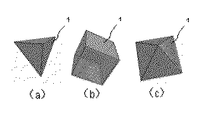
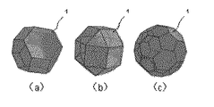
また、ワイピングローラ(7)の洗浄に用いる洗浄粒子(1)は、洗浄液(15)による腐蝕、劣化が抑制される材質であればよく、例えば、ステンレス鋼のような金属類、PVC(塩化ビニル)のような樹脂類、NBR(ニトリルゴム)のようなゴム類のいずれかの材質により形成している。また、洗浄粒子(1)の形状を多面体形状としている。図5及び図6に代表的な洗浄粒子(1)の形状を示している。例えば、図5(a)に示すように洗浄粒子(1)の形状を正四面体とすること、図5(b)に示すように正六面体とすること、図5(c)に示すように正八面体とするような正多面体形状に設計する場合や、図6(a)に示すように切頂八面体とすること、図6(b)に示すように斜方立方八面体とすること、図6(c)に示すように切頂二十面体とするような半正多面体形状に設計する場合がある。なお、洗浄粒子(1)の大きさは、粒子径2mm〜8mmの範疇にて任意に形成している。 The cleaning particles (1) used for cleaning the wiping roller (7) may be any material that can be prevented from being corroded and deteriorated by the cleaning liquid (15). For example, metals such as stainless steel, PVC (vinyl chloride) ) Or a rubber such as NBR (nitrile rubber). The shape of the cleaning particles (1) is a polyhedral shape. FIG. 5 and FIG. 6 show the shape of a typical cleaning particle (1). For example, the shape of the cleaning particles (1) is a regular tetrahedron as shown in FIG. 5 (a), a regular hexahedron as shown in FIG. 5 (b), and as shown in FIG. 5 (c). When designing into a regular polyhedron shape such as a regular octahedron, a truncated octahedron as shown in FIG. 6 (a), an orthorhombic cubic octahedron as shown in FIG. 6 (b), As shown in FIG.6 (c), it may design to a semi-regular polyhedral shape which makes it a truncated icosahedron. In addition, the magnitude | size of the washing | cleaning particle | grains (1) is arbitrarily formed in the category of particle diameter 2mm-8mm.
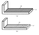
また、ワイピングローラ(7)に接触した後、自重沈殿により降下した洗浄粒子(1)を載置する洗浄粒子載置用部材(17)の材質についても、洗浄液(15)への耐抗性が良好な材質であればよく、金属類、樹脂類、ゴム類のいずれでもよい。また、洗浄粒子載置用部材(17)の形状としては、図7(a)に示すように格子状メッシュ(18)とする場合や、図7(b)に示すようにスルーホール(19)とする場合がある。ここでは、ワイピングローラ(7)から乖離したインキ滓が洗浄粒子載置用部材(17)に堆積しないように、十分な開孔率(90%〜98%)を有した洗浄粒子載置用部材(17)としている。例えば、線径0.10mm〜0.20mm、目開き0.20〜0.30mm、メッシュ数50〜80としたステンレスメッシュ(18)とする場合や、センターピッチ5mm以下、角度45°以下の千鳥抜とし、インキ抜けを阻害しない程度の十分な孔径を有したスルーホールであるパンチメタル(19)とした場合がある。 Further, the material of the cleaning particle mounting member (17) on which the cleaning particles (1) lowered by the self-weight precipitation after contacting the wiping roller (7) are also resistant to the cleaning liquid (15). Any suitable material may be used, and any of metals, resins, and rubbers may be used. Further, the shape of the cleaning particle mounting member (17) may be a lattice mesh (18) as shown in FIG. 7 (a) or a through hole (19) as shown in FIG. 7 (b). It may be. Here, the cleaning particle mounting member having a sufficient aperture ratio (90% to 98%) so that the ink fountain separated from the wiping roller (7) does not accumulate on the cleaning particle mounting member (17). (17). For example, when a stainless steel mesh (18) having a wire diameter of 0.10 mm to 0.20 mm, an opening of 0.20 to 0.30 mm, and a mesh number of 50 to 80 is used, or a zigzag with a center pitch of 5 mm or less and an angle of 45 ° or less. In some cases, the punch metal (19) is a through hole having a sufficient hole diameter that does not hinder ink removal.
また、吐出圧供給装置(16)は、十分な開孔率を有している洗浄粒子載置用部材(17)の下部に配置され、洗浄粒子載置用部材(17)を介して洗浄粒子(1)に例えば、溶剤、水、油、空気等の媒体を、一つのノズル当り吐出圧0.1MPa〜2.0MPa、流量10ml/min〜500ml/minにて供給することが可能である。また、媒体の供給量は任意に可変することが可能である。また、吐出圧供給装置(16)に用いる媒体については、使用するインキの性質に対応させて、任意に選択することになる。なお、本洗浄機構は、非浸漬型ワイピング装置に用いた場合には効果が乏しく、洗浄液(15)をワイピング槽(6)に滞留させた浸漬型ワイピング装置に用いることで大きな効果を発揮する。 Further, the discharge pressure supply device (16) is disposed below the cleaning particle mounting member (17) having a sufficient aperture ratio, and the cleaning particles are placed via the cleaning particle mounting member (17). In (1), for example, a medium such as a solvent, water, oil, or air can be supplied at a discharge pressure of 0.1 MPa to 2.0 MPa and a flow rate of 10 ml / min to 500 ml / min per nozzle. Further, the supply amount of the medium can be arbitrarily changed. The medium used for the discharge pressure supply device (16) is arbitrarily selected according to the properties of the ink used. Note that this cleaning mechanism is less effective when used in a non-immersion type wiping apparatus, and exhibits a great effect when used in an immersion type wiping apparatus in which the cleaning liquid (15) is retained in the wiping tank (6).
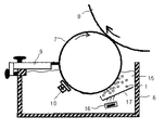
また、図2に示すように、本発明のワイピング装置は、洗浄粒子(1)にてワイピングローラ(7)の洗浄を行う洗浄機構の下流に残存するインキ滓を吸引及び回収する吸引装置(10)を備えており、また、最下流にワイピングローラ(7)の表面を完全に洗浄する仕上げブレード(9)を配置している態様とする場合もある。ここで、吸引装置(10)は、ワイピング槽(6)に固着された支軸(2)に固定されている態様である。なお、吸引装置(10)は、図示しない制御装置によりワイピングローラ(7)への接触状態及び吸引量を自在に調整することが可能である。 As shown in FIG. 2, the wiping device of the present invention is a suction device (10) that sucks and collects ink fountain remaining downstream of the cleaning mechanism that cleans the wiping roller (7) with the cleaning particles (1). ) And a finishing blade (9) that completely cleans the surface of the wiping roller (7) may be disposed on the most downstream side. Here, the suction device (10) is a mode fixed to the support shaft (2) fixed to the wiping tank (6). The suction device (10) can freely adjust the contact state and suction amount to the wiping roller (7) by a control device (not shown).
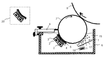
また、本発明のワイピング装置は、図3に示すように洗浄粒子(1)にてワイピングローラ(7)の洗浄を行う洗浄機構の下流に残存するインキ滓を除去する複数列のブラシ群の上にインキの抜けを阻害しない開き目を有し、かつ柔軟性がある合成繊維製不織布(例えば、タワシ)又は樹脂を載せ、ワイピングローラと面接触する機能を有する洗浄補助機構(20)を備えており、また、最下流にワイピングローラ(7)の表面を完全に洗浄する仕上げブレード(9)を配置している態様とする場合もある。 Further, as shown in FIG. 3, the wiping device of the present invention is provided on a plurality of rows of brush groups for removing ink fountain remaining downstream of a cleaning mechanism for cleaning the wiping roller (7) with cleaning particles (1). A cleaning auxiliary mechanism (20) having a function of contacting the surface of the wiping roller with a synthetic fiber nonwoven fabric (for example, scrubbing) or resin having an opening that does not hinder ink omission In some cases, a finishing blade (9) that completely cleans the surface of the wiping roller (7) is disposed on the most downstream side.
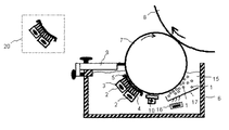
さらに、本発明のワイピング装置は、図4に示すように洗浄粒子(1)にてワイピングローラ(7)の洗浄を行う洗浄機構の下流に上述した吸引装置(10)及び洗浄補助機構(20)を併用して配置しており、また、最下流にワイピングローラ(7)の表面を完全に洗浄する仕上げブレード(9)を配置している態様とする場合もある。 Furthermore, as shown in FIG. 4, the wiping device of the present invention has the above-described suction device (10) and cleaning auxiliary mechanism (20) downstream of the cleaning mechanism that cleans the wiping roller (7) with the cleaning particles (1). The finishing blade (9) that completely cleans the surface of the wiping roller (7) may be disposed at the most downstream side.
本発明における実施の例示について詳細に説明する。図1に示すように本発明の凹版印刷機のワイピング装置は、凹版胴(8)に装着された図示しない凹版版面から対接するワイピングローラ(7)にて拭き取ったインキ滓等の余剰インキを洗浄する方法として、約150リットルの洗浄液(15)を滞留させたワイピング槽(6)の内部に設置した粒子径を約4mm、材質をステンレス鋼、形状を図6(c)に示すように半正多面体である切頂二十面体として作製した約300個の洗浄粒子(1)と、この洗浄粒子(1)をワイピングローラ(7)に指向し、吐出圧1.5MPa、流量300ml/minの洗浄液(15)を投射させる吐出圧供給装置(16)と、自重沈殿にて降下した洗浄粒子(1)を載置する線径0.15mm、目開き0.24mm、メッシュ数60であるステンレスメッシュ(18)をL型形状とした洗浄粒子載置用部材(19)とから形成した洗浄機構により、約50万枚の凹版印刷を実施した。なお、ワイピングローラ(7)には、表面に塩化ビニル樹脂(PVC)を巻き付けたものを使用しており、また、ワイピング槽(6)には、ワイピングローラ(7)からのインキ滓の乖離状態を観察するため、一部に透明樹脂製の観察用小窓を取設したものを使用した。 Examples of implementation in the present invention will be described in detail. As shown in FIG. 1, the wiping device for an intaglio printing press according to the present invention cleans excess ink such as ink fountains wiped by a wiping roller (7) that contacts an intaglio plate surface (not shown) mounted on an intaglio cylinder (8). As a method, a particle diameter of about 4 mm, a material of stainless steel, and a shape of half positive as shown in FIG. 6C are placed inside a wiping tank (6) in which about 150 liters of cleaning liquid (15) is retained. About 300 cleaning particles (1) prepared as a truncated icosahedron that is a polyhedron, and the cleaning particles (1) are directed to the wiping roller (7), and the cleaning liquid has a discharge pressure of 1.5 MPa and a flow rate of 300 ml / min. (15) and a discharge pressure supply device (16), and a stainless steel device having a wire diameter of 0.15 mm, a mesh opening of 0.24 mm, and a mesh number of 60 on which the cleaning particles (1) lowered by the self-weight precipitation are placed. The cleaning mechanism that shoe (18) is formed from the cleaning particles placing member which is L-shaped (19), was performed approximately 500,000 sheets of intaglio printing. The wiping roller (7) has a surface wrapped with vinyl chloride resin (PVC), and the wiping tank (6) has an ink fountain separated from the wiping roller (7). In order to observe the above, a transparent resin observation window made in part was used.
最初に、吐出圧供給装置(16)から供給された洗浄液(15)により、洗浄粒子(1)がワイピングローラ表面上に存するインキ滓と接触しており、該インキ滓はワイピングローラ(7)から乖離している状態になっていた。また、一部、洗浄粒子(1)に一時的に接着したインキ滓についても洗浄液中を降下する段階において、乖離している状態になっていた。 First, the cleaning particles (1) are in contact with the ink fountain existing on the surface of the wiping roller by the cleaning liquid (15) supplied from the discharge pressure supply device (16), and the ink fountain comes from the wiping roller (7). It was in a state of divergence. In addition, the ink fountain temporarily adhered to the cleaning particles (1) was in a state of being separated at the stage of descending the cleaning liquid.
次に、吐出圧供給装置(16)から供給された洗浄液(15)により、ワイピングローラ(7)に投射された洗浄粒子(1)は、ローラに接触後、自重沈殿にて洗浄粒子載置用部材(17)に載置されることになる。この時、洗浄粒子載置用部材(17)は所定角度の傾き(実施例では、30°)を有しており、吐出圧供給装置(16)からの媒体が効率よく洗浄粒子(1)に供給できるようになっている。その後再び吐出圧供給装置(16)から供給された洗浄液(15)により、洗浄粒子(1)はローラに向けて投射されることになるが、その際、吐出する洗浄液(15)により、洗浄粒子(15)はクリーニングされていたことを確認した。また、洗浄液中に分散されたインキ滓については、洗浄粒子載置用部材(17)の開孔部を抜けてワイピング槽(6)の底部に沈積していることを確認した。 Next, the cleaning particles (1) projected onto the wiping roller (7) by the cleaning liquid (15) supplied from the discharge pressure supply device (16) come into contact with the rollers, and then are placed on the cleaning particles by self-weight precipitation. It will be mounted on a member (17). At this time, the cleaning particle mounting member (17) has a predetermined angle of inclination (in the embodiment, 30 °), and the medium from the discharge pressure supply device (16) efficiently becomes the cleaning particles (1). It can be supplied. Thereafter, the cleaning liquid (15) supplied from the discharge pressure supply device (16) again projects the cleaning particles (1) toward the roller. At this time, the cleaning liquid (15) discharged discharges the cleaning particles. (15) confirmed that it was cleaned. Further, it was confirmed that the ink fountain dispersed in the cleaning liquid passed through the opening of the cleaning particle mounting member (17) and was deposited on the bottom of the wiping tank (6).
また、ワイピング装置稼動中におけるワイピングローラ(7)の表面温度を非接触式温度計にて測定した結果、従前のワイピング装置を用いた場合、印刷使用前の約60℃から2時間印刷後の表面温度が約67℃となるのに対して、本発明のワイピング装置を用いた場合、ワイピングローラ(7)の表面温度は、同条件において印刷使用前の約60℃から2時間印刷後の表面温度が約61℃であった。また、ワイピング装置稼働中におけるワイピングローラ(7)の表面凹凸状態の変動についても確認したが、従前技術に比して凹凸発生程度が小さく、至って良好な状態であることを確認した。なお、表面凹凸状態の計測にはレーザ式変位計を用いており、検出値は電波により図示しない表示装置に出力することが可能である。 Further, as a result of measuring the surface temperature of the wiping roller (7) during operation of the wiping device with a non-contact type thermometer, the surface after printing for about 2 hours from about 60 ° C. before printing is used when the conventional wiping device is used. Whereas the temperature is about 67 ° C., when the wiping device of the present invention is used, the surface temperature of the wiping roller (7) is the surface temperature after printing for 2 hours from about 60 ° C. before printing use under the same conditions. Was about 61 ° C. Moreover, although the fluctuation | variation of the surface uneven | corrugated state of the wiping roller (7) during operation of a wiping apparatus was also confirmed, the uneven | corrugated generation | occurrence | production degree was small compared with the prior art, and it confirmed that it was in a very favorable state. Note that a laser displacement meter is used to measure the surface unevenness, and the detected value can be output to a display device (not shown) by radio waves.
また、洗浄粒子(1)の形状を図5(b)に示すように正多面体である正六面体とした場合、図6(b)に示すように半正多面体である斜方立方八面体とした場合についても同様の条件において確認した。その結果、いずれについても、おおよそ良好な洗浄結果を得ることができた。但し、細かく観察すると、正多面体形状の洗浄粒子(1)を用いた場合は、洗浄液の吐出圧、流量ともに大きく設定する必要があることを確認した。これは、用いるインキの性質にも左右されるが、ワイピングローラ表面に固着したインキ滓を乖離させるためには、稜を多く有する多面体を用いることが有利であるということを確認した。 Further, when the shape of the cleaning particles (1) is a regular hexahedron as shown in FIG. 5 (b), an orthorhombic cubic octahedron as a half regular polyhedron is used as shown in FIG. 6 (b). The cases were confirmed under the same conditions. As a result, almost good cleaning results could be obtained for both. However, when closely observed, it was confirmed that when the regular polyhedral-shaped cleaning particles (1) were used, it was necessary to set both the discharge pressure and the flow rate of the cleaning liquid to be large. Although this depends on the properties of the ink used, it has been confirmed that it is advantageous to use a polyhedron having many ridges in order to separate the ink fountain fixed on the surface of the wiping roller.
また、洗浄粒子(1)の使用個数についても変動させて確認したが、洗浄粒子(1)を多量(例えば、500個)に用いると、ワイピングローラ(7)への投射時に互いの洗浄粒子(1)が干渉し合い有用ではない。また、洗浄粒子(1)を少量(例えば、50個)とすると、洗浄効果として満足し難い結果となることを確認した。同様に、洗浄粒子(1)の粒子径についても変動させて確認したが、洗浄粒子(1)を大きく設計するとワイピングローラ(7)への投射時に互いの洗浄粒子(1)が干渉し合い有用ではなく、洗浄粒子(1)を小さく設計とすると、洗浄効果として満足し難い結果となることを確認した。 Moreover, although the number of cleaning particles (1) used was also varied and confirmed, when a large amount (for example, 500 particles) of cleaning particles (1) are used, each cleaning particle (1) is projected on the wiping roller (7). 1) interferes with each other and is not useful. In addition, it was confirmed that when the amount of the cleaning particles (1) is small (for example, 50), the cleaning effect is hardly satisfied. Similarly, the particle diameter of the cleaning particles (1) was confirmed to be varied, but if the cleaning particles (1) are designed to be large, the cleaning particles (1) interfere with each other when projected onto the wiping roller (7), which is useful. Instead, it was confirmed that if the cleaning particle (1) is designed to be small, the cleaning effect is hardly satisfied.
また、洗浄液(15)の吐出圧、流量についても変動させて確認したが、吐出圧、流量ともに極端に大きく設定すると、洗浄液(15)がはく離し乱流状態になりやすく、洗浄効果が低下することから有用でないことを確認した。また、吐出圧、流量ともに極端に小さく設定すると、洗浄粒子(1)がワイピングローラ(7)の表面に存するインキ滓を乖離し難くなるので有用でないことを確認した。 Further, although the discharge pressure and flow rate of the cleaning liquid (15) were also varied, it was confirmed that if both the discharge pressure and flow rate are set to be extremely large, the cleaning liquid (15) tends to peel off and become a turbulent state, and the cleaning effect is reduced. This confirmed that it was not useful. Further, it was confirmed that if both the discharge pressure and the flow rate are set to be extremely small, the cleaning particles (1) are not useful because they are difficult to separate the ink fountain existing on the surface of the wiping roller (7).
さらに、粘性の高いインキを用いた場合として、上述した洗浄機構の下流に残存するインキ滓成分を吸引及び回収する吸引装置(10)を配置した場合、また、複数列のブラシ群の上に合成繊維製不織布(例えば、タワシ)を載せ、ワイピングローラ(7)と面接触する機能を有する洗浄補助機構(20)を配置した場合、また、上述した吸引装置(10)及び洗浄補助機構(20)を併用して配置した場合についても確認した。いずれについても有用な結果が得られることを鋭意努力した結果、我々は承知している。 Furthermore, when a highly viscous ink is used, a suction device (10) for sucking and collecting the ink fountain component remaining downstream of the above-described cleaning mechanism is disposed, and the composition is combined on a plurality of rows of brush groups. When a non-woven fabric made of fiber (for example, scrubbing) is placed and a cleaning auxiliary mechanism (20) having a function of making surface contact with the wiping roller (7) is disposed, the above-described suction device (10) and cleaning auxiliary mechanism (20) are also provided. It confirmed also when arranging together. We are aware of the results of our diligent efforts to obtain useful results.
上述したいずれの実施例においても、ワイピングローラ(7)の表面に存するインキ滓等が確実に除去できており、ワイピングローラ(7)の表面には光沢がある状態であった。また、枚葉紙約50万枚印刷後においてもワイピングローラ(7)の拭き取り能力は目立って劣化しているものではなく、さらなる印刷を実施することが可能であった。 In any of the above-described embodiments, the ink fountain and the like existing on the surface of the wiping roller (7) can be reliably removed, and the surface of the wiping roller (7) is in a glossy state. Further, even after printing about 500,000 sheets of paper, the wiping capability of the wiping roller (7) was not noticeably deteriorated, and further printing could be performed.
上述した実施例はあくまで例示の一例に過ぎず、特許請求の範囲に記載されている範囲において、あらゆる実施の形態が存在することは言うまでもない。実施例では、洗浄粒子(1)を投射する吐出圧供給装置(16)を1箇所に配置したが、当然、複数箇所に配置することや、任意に洗浄粒子(1)への投射角度を変更する場合なども容易に推量できるものである。 The above-described embodiments are merely examples, and it goes without saying that all embodiments exist within the scope described in the claims. In the embodiment, the discharge pressure supply device (16) for projecting the cleaning particles (1) is arranged in one place, but naturally, it is arranged in a plurality of places, and the projection angle to the washing particles (1) is arbitrarily changed. It can be easily guessed when doing so.
1 洗浄粒子
2 支軸
3 洗浄部材
4 ブラシ群
5 合成繊維製不織布(タワシ)
6 ワイピング槽
7 ワイピングローラ
8 凹版胴
9 仕上げブレード
10 吸引装置
11 補助ブレード
12 噴射装置
13 噴射ノズル
14 中間噴射装置
15 洗浄液
16 吐出圧供給装置
17 洗浄粒子載置用部材
18 格子状メッシュ
19 スルーホール(パンチメタル)
20 洗浄補助機構
DESCRIPTION OF
6
20 Cleaning assist mechanism
Claims (7)
Priority Applications (1)
| Application Number | Priority Date | Filing Date | Title |
|---|---|---|---|
| JP2008323332A JP2010143101A (en) | 2008-12-19 | 2008-12-19 | Wiping device of letterpress machine |
Applications Claiming Priority (1)
| Application Number | Priority Date | Filing Date | Title |
|---|---|---|---|
| JP2008323332A JP2010143101A (en) | 2008-12-19 | 2008-12-19 | Wiping device of letterpress machine |
Publications (1)
| Publication Number | Publication Date |
|---|---|
| JP2010143101A true JP2010143101A (en) | 2010-07-01 |
Family
ID=42564024
Family Applications (1)
| Application Number | Title | Priority Date | Filing Date |
|---|---|---|---|
| JP2008323332A Pending JP2010143101A (en) | 2008-12-19 | 2008-12-19 | Wiping device of letterpress machine |
Country Status (1)
| Country | Link |
|---|---|
| JP (1) | JP2010143101A (en) |
Cited By (1)
| Publication number | Priority date | Publication date | Assignee | Title |
|---|---|---|---|---|
| US8857334B2 (en) | 2012-03-05 | 2014-10-14 | Samsung Electronics Co., Ltd | Cleaning apparatuses for printing plates and printing apparatuses including the same |
-
2008
- 2008-12-19 JP JP2008323332A patent/JP2010143101A/en active Pending
Cited By (1)
| Publication number | Priority date | Publication date | Assignee | Title |
|---|---|---|---|---|
| US8857334B2 (en) | 2012-03-05 | 2014-10-14 | Samsung Electronics Co., Ltd | Cleaning apparatuses for printing plates and printing apparatuses including the same |
Similar Documents
| Publication | Publication Date | Title |
|---|---|---|
| JP5433794B2 (en) | Rolling roll cleaning apparatus and cleaning method | |
| JP5277502B2 (en) | Intaglio printing machine wiping device | |
| US9381745B1 (en) | Printhead cleaning assembly | |
| JP3709537B2 (en) | Intaglio printing machine wiping device | |
| TWI327488B (en) | ||
| JP2006159880A (en) | Cylinder cleaning device for printing machine | |
| JP2018047609A (en) | Wiping device and discharge device | |
| US20030167948A1 (en) | Method and apparatus for steam cleaning anilox inking rollers | |
| JP2016129933A (en) | Wiping device including vibration mechanism using ultrasonic wave and ultrasonic wave control method | |
| JP2010143101A (en) | Wiping device of letterpress machine | |
| JP2008302533A (en) | Wiper blade of wiping mechanism for ink jet device | |
| CN100431714C (en) | Nozzle cleaning device | |
| CN103466956B (en) | Start filling treatment process and start filling treatment unit | |
| JP2009255455A (en) | Wiping apparatus and method of intaglio printing machine | |
| CN105327952A (en) | Cleaning system for improving roller surface wear of polishing machine | |
| US20160355018A1 (en) | Ink jet printer with maintenance unit | |
| CN109049985A (en) | A kind of automatic cleaning apparatus of inkjet style printer piezoelectric type spray head | |
| JP4135964B1 (en) | Silicone film repair method | |
| JP2013014116A (en) | Wiping device for intaglio printing machine | |
| JP2015120277A (en) | Intaglio printing machine wiping device | |
| JP2011084042A (en) | Wiping device of intaglio printing machine | |
| TWI704062B (en) | Pollution prevention device for ink tank for offset printing machine | |
| JP2011189691A (en) | Cleaning member for wiping roller of intaglio printing machine and method for shaping cleaning member | |
| JP2018158497A (en) | Wiping cleaning device for intaglio printing press | |
| JPH11268252A (en) | Wiping device for intaglio printing press |