JP2010143052A - Image forming apparatus - Google Patents
Image forming apparatus Download PDFInfo
- Publication number
- JP2010143052A JP2010143052A JP2008322191A JP2008322191A JP2010143052A JP 2010143052 A JP2010143052 A JP 2010143052A JP 2008322191 A JP2008322191 A JP 2008322191A JP 2008322191 A JP2008322191 A JP 2008322191A JP 2010143052 A JP2010143052 A JP 2010143052A
- Authority
- JP
- Japan
- Prior art keywords
- image data
- unit
- transfer destination
- processing unit
- data
- Prior art date
- Legal status (The legal status is an assumption and is not a legal conclusion. Google has not performed a legal analysis and makes no representation as to the accuracy of the status listed.)
- Pending
Links
Images


Abstract
Description
本発明は、画像形成媒体に画像形成するためのノズル群を画像データに基づいて制御する画像形成装置に関する。 The present invention relates to an image forming apparatus that controls a nozzle group for forming an image on an image forming medium based on image data.
従来、用紙の幅方向の一列全体に対してインクを吐出させることのできるヘッド列を備え、ヘッドの移動を伴わずに用紙幅方向の印刷が可能なラインインクジェットプリンターが知られている。このようなラインインクジェットプリンターにおいては、例えば、高画質化や多色化を実現するために、ヘッド列を用紙の搬送方向に複数並べているものがある。 2. Description of the Related Art Conventionally, a line inkjet printer that includes a head row that can eject ink over an entire row in the paper width direction and that can print in the paper width direction without moving the head is known. In such a line ink jet printer, for example, in order to realize high image quality and multiple colors, a plurality of head arrays are arranged in the paper transport direction.
例えば、このようなラインインクジェットプリンターにおいては、ヘッド列が複数のヘッドにより構成され、各ヘッド(各ヘッドに形成されたノズル群)を制御するための複数のヘッドコントローラーが備えられているものがある。このようなラインインクジェットプリンターにおいては、外部装置から受信した画像データを複数のヘッドコントローラーに転送する必要がある。 For example, in such a line inkjet printer, there is a type in which a head row is configured by a plurality of heads and a plurality of head controllers for controlling each head (a group of nozzles formed in each head). . In such a line inkjet printer, it is necessary to transfer image data received from an external device to a plurality of head controllers.
例えば、1つの基板上に形成された処理部により、複数のヘッドコントローラーに画像データを転送するためには、当該基板上にヘッドコントローラーへのデータの出力口(スロット)を複数設ける必要がある。この場合には、基板上の配線が多くなり物理的に難しくなると共に、ノイズの影響も大きくなるという問題が生じる虞がある。 For example, in order to transfer image data to a plurality of head controllers by a processing unit formed on one substrate, it is necessary to provide a plurality of data output ports (slots) to the head controller on the substrate. In this case, there is a possibility that a problem arises that the number of wirings on the substrate increases and it becomes physically difficult, and the influence of noise increases.
これに対して、ある程度の数のヘッドコントローラーと接続可能な分配処理部を複数備え、外部装置から受信した画像データを転送処理部が複数の分配処理部に送信し、分配処理部が画像データをそれぞれに接続されたヘッドコントローラーに送信することが考えられている。この場合には、転送処理部が複数の分配処理部に対して画像データを送信する必要がある。 In contrast, a plurality of distribution processing units that can be connected to a certain number of head controllers are provided, the transfer processing unit transmits image data received from an external device to the plurality of distribution processing units, and the distribution processing unit receives the image data. It is considered to transmit to each head controller connected to each. In this case, the transfer processing unit needs to transmit image data to a plurality of distribution processing units.
例えば、複数の通信対象物の間におけるデータ通信の技術としては、例えば、主制御器と、複数の従制御器との間をデータバスと制御バスで接続し、主制御器と任意の従制御器との間で相互伝送を可能とする技術が知られている(例えば、特許文献1参照)。 For example, as a technique of data communication between a plurality of communication objects, for example, a master controller and a plurality of slave controllers are connected by a data bus and a control bus, and the master controller and an arbitrary slave control are connected. A technique that enables mutual transmission between devices is known (for example, see Patent Document 1).
例えば、転送処理部が複数の分配処理部に対して画像データを送信する構成として、特許文献1の技術を用いると、転送処理部と、複数の分配処理部との配線長が異なっているので、適切に信号を受信できるようにするための設計が困難である。また、新たに分配処理部を追加するように構成を拡張する際においては、追加する分配処理部と転送処理部とのインピーダンス整合等を考慮する必要があり、非常に困難である。また、分配処理部の数の異なる装置を新たに作成する際にも、各分配処理部と転送処理部とのインピーダンス整合等を考慮する必要があり、非常に設計が困難である。
For example, if the technique of
一方、プリンターが故障した際には、迅速且つ容易にメンテナンスできることが要請されている。 On the other hand, when a printer breaks down, it is required that maintenance can be performed quickly and easily.
本発明は、上記課題に鑑みなされたものであり、その目的は、装置の拡張、構成変更、設計変更等を容易に行うことのできる技術を提供することにある。また、他の目的は、迅速且つ容易にメンテナンスすることのできる技術を提供することにある。 The present invention has been made in view of the above problems, and an object thereof is to provide a technique capable of easily performing expansion, configuration change, design change, and the like of an apparatus. Another object is to provide a technique that can be maintained quickly and easily.
上記目的達成のため、本発明の第1の態様に係る画像形成装置は、画像形成媒体に画像形成するためのノズル群を画像データに基づいて制御する複数のコントローラーと、複数のコントローラーの内の一部のコントローラーに接続され、当該コントローラーが担当する前記ノズル群を制御するための画像データを、コントローラーに送信する複数の分配処理部と、複数の分配処理部に画像データを転送するための転送処理部とを有する画像形成装置であって、最上位となる第1の分配処理部から最下位となる第2の分配処理部まで、上位の分配処理部と下位の分配処理部とが通信可能に接続されるとともに、第1の分配処理部は、転送処理部と通信可能に接続されて構成され、転送処理部は、画像データを記憶するメモリーと、転送先とするコントローラーを示す転送先識別情報を決定する転送先決定手段と、転送先のコントローラーに送信する画像データをメモリーから読み出す画像データ読出手段と、転送先識別情報と画像データとを第1の分配処理部に送信するデータ送信手段とを有し、分配処理部は、転送処理部又は上位の分配処理部から画像データと、転送先識別情報とを受信する受信手段と、受信した転送先識別情報が示すコントローラーが、当該分配処理部自身が担当するコントローラーである場合に、受信した画像データをコントローラーに送信する配信手段と、画像データと、転送先識別情報とを下位の分配処理部に送信する下位送信手段とを有する。 To achieve the above object, an image forming apparatus according to a first aspect of the present invention includes a plurality of controllers that control a nozzle group for forming an image on an image forming medium based on image data, and a plurality of controllers among the plurality of controllers. A plurality of distribution processing units that are connected to a part of the controller and transmit the image data for controlling the nozzle group that the controller is responsible for to the controller, and a transfer for transferring the image data to the plurality of distribution processing units An image forming apparatus having a processing unit, wherein a higher-level distribution processing unit and a lower-level distribution processing unit can communicate from a first distribution processing unit as the highest level to a second distribution processing unit as the lowest level. And the first distribution processing unit is configured to be communicably connected to the transfer processing unit. The transfer processing unit is a memory for storing image data and a transfer destination. Transfer destination determining means for determining transfer destination identification information indicating a controller, image data reading means for reading out image data to be transmitted to a transfer destination controller from the memory, transfer destination identification information and image data in a first distribution process The distribution processing unit includes: a receiving unit that receives image data and transfer destination identification information from the transfer processing unit or a higher-level distribution processing unit; and the received transfer destination identification information When the controller shown is the controller that the distribution processing unit itself is in charge of, the distribution unit that transmits the received image data to the controller, the lower level that transmits the image data and the transfer destination identification information to the lower distribution processing unit Transmitting means.
係る画像形成装置によると、各分配処理部は、受信した転送先識別情報が示すコントローラーが、当該分配処理部自身が担当するコントローラーである場合に、受信した画像データをコントローラーに送信し、また、転送先識別情報と画像データとを下位の分配処理部に送信する。このため、最下位の分配処理部に対して、新たな分配処理部を接続することにより、新たな分配処理部に対して画像データを送信させることができる。したがって、新たな分配処理部に接続されたコントローラーを示す転送先識別情報を指定することにより、新たな分配処理部に接続されたコントローラーに対して画像データを適切に送信することができる。 According to such an image forming apparatus, each distribution processing unit transmits the received image data to the controller when the controller indicated by the received transfer destination identification information is the controller in charge of the distribution processing unit itself, The transfer destination identification information and the image data are transmitted to the lower distribution processing unit. For this reason, by connecting a new distribution processing unit to the lowest distribution processing unit, image data can be transmitted to the new distribution processing unit. Therefore, by specifying the transfer destination identification information indicating the controller connected to the new distribution processing unit, it is possible to appropriately transmit the image data to the controller connected to the new distribution processing unit.
また、上記画像形成装置において、転送処理部は、外部装置から分配処理部へのコントローラーの接続状態を示す状態情報を受信する状態情報受信手段を更に有し、転送先決定手段は、状態情報に基づいて、画像データの転送先識別情報を決定するようにしてもよい。係る画像形成装置によると、分配処理部へのコントローラーの接続状態に基づいて、画像データの転送先を決定するので、コントローラーが接続された分配処理部に対して適切に画像データを送信し、当該コントローラーに画像データを転送させることができる。このため、例えば、1以上のコントローラーを接続可能な分配処理部を備えておき、他の分配処理部においてコントローラーを接続できない故障が生じた場合に、接続可能な分配処理部を用いてコントローラーを接続させるようにすることができる。これにより、故障時に迅速かつ容易にメンテナンスすることができる。 In the image forming apparatus, the transfer processing unit further includes a status information receiving unit that receives status information indicating a connection state of the controller from the external device to the distribution processing unit, and the transfer destination determining unit includes the status information. Based on this, the transfer destination identification information of the image data may be determined. According to the image forming apparatus, since the transfer destination of the image data is determined based on the connection state of the controller to the distribution processing unit, the image data is appropriately transmitted to the distribution processing unit to which the controller is connected. Image data can be transferred to the controller. For this reason, for example, a distribution processing unit to which one or more controllers can be connected is provided, and a controller is connected using a connectable distribution processing unit in the event that a failure occurs in which other controllers cannot be connected. You can make it. Thereby, maintenance can be performed quickly and easily at the time of failure.
また、上記画像形成装置において、複数の分配処理部は、ハードウエア構成が同一であってもよい。係る画像形成装置によると、分配処理部を製造するコストを低減することができる。 In the image forming apparatus, the plurality of distribution processing units may have the same hardware configuration. According to such an image forming apparatus, the cost of manufacturing the distribution processing unit can be reduced.
また、上記画像形成装置において、分配処理部は、転送処理部又は上位の分配処理部とを通信可能に接続するための上位コネクターと、下位の分配処理部とを通信可能に接続するための下位コネクターとを有し、上位コネクターと下位コネクターとは、分配処理部を構成するためのボードに対して略対称な位置に配置されていてもよい。係る画像形成装置によると、分配処理部を同一形状とすることができ、分配処理部を製造するコストを低減することができる。 Further, in the image forming apparatus, the distribution processing unit includes a host connector for communicatively connecting a transfer processing unit or a higher-order distribution processing unit and a lower-level connector for communicatively connecting a lower-level distribution processing unit. The upper connector and the lower connector may be arranged at a position that is substantially symmetric with respect to the board for configuring the distribution processing unit. According to such an image forming apparatus, the distribution processing unit can have the same shape, and the cost for manufacturing the distribution processing unit can be reduced.
本発明の実施形態について、図面を参照して説明する。なお、以下に説明する実施形態は特許請求の範囲に係る発明を限定するものではなく、また実施形態の中で説明されている諸要素及びその組み合わせの全てが発明の解決手段に必須であるとは限らない。 Embodiments of the present invention will be described with reference to the drawings. The embodiments described below do not limit the invention according to the claims, and all the elements and combinations described in the embodiments are essential for the solution of the invention. Is not limited.
まず、本発明の第1実施形態に係る画像形成装置の一例としてのラインインクジェットプリンター(以下、プリンターという)を含む画像形成システムを説明する。 First, an image forming system including a line inkjet printer (hereinafter referred to as a printer) as an example of an image forming apparatus according to a first embodiment of the present invention will be described.
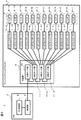
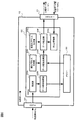
図1は、本発明の第1実施形態に係る画像形成システムの構成図である。 FIG. 1 is a configuration diagram of an image forming system according to the first embodiment of the present invention.
画像形成システム1は、PC(Personal Computer)2と、プリンター3とを有する。
The
PC2は、PC本体部4と、転送部5とを有する。PC本体部4は、例えば、CPU(Central Processing Unit)、ROM(Read Only Memory)、RAM(Random Access Memory)等を有し、プリンター3に印刷させる画像データを生成し、転送部5に渡す処理を実行する。転送部5は、PC本体部4から受け取った画像データに基づいて、プリンター3用の画像データを生成する。転送部5は、例えば、プリンター3により形成する1枚の画像についての各色(例えば、C(シアン)、M(マゼンタ)、Y(イエロー)、K(ブラック))ごとの画像データを生成する。また、転送部5は、各色毎の画像データをプリンター3に送信する。
The PC 2 includes a PC
また、転送部5は、プリンター3の分配部6を設定するための分配部設定情報を送信する。本実施形態では、分配部設定情報は、印刷する画像の色数と、搬送方向の画像サイズと、幅方向の画像サイズと、ヘッドコントローラー接続状態情報とを含む。ヘッドコントローラー接続状態情報とは、分配部6の分配ボード部11のスロット27に対するヘッドコントローラー7の接続状態(接続有無)を示す情報であり、例えば、各スロット27における接続状態を示すデータとしてそれぞれ1ビットずつ割り当て、対応するスロット27にヘッドコントローラー7が接続されている場合には、ビットを”1”とし、接続されていない場合には、ビットを”0”とするようにしている。
Further, the
プリンター3は、分配部6と、複数(例えば、12個)のヘッドコントローラー7−1〜7−12(特定のヘッドコントローラーを示さない場合には、ヘッドコントローラー7と記載する場合がある)と、複数(例えば、12個)のヘッド8−1〜8−12(特定のヘッドを示さない場合には、ヘッド8と記載する場合がある)とを有する。本実施形態では、1つのヘッドコントローラー7は、1つのヘッド8に接続され、当該1つのヘッド8を制御するようになっている。なお、1つのヘッドコントローラー7が複数のヘッド8に接続され、複数のヘッド8を制御するようにしてもよい。分配部6は、受信ボード部(転送処理部)10と、複数の分配ボード部(分配処理部)11−1〜11−3(特定の分配ボード部を示さない場合には、分配ボード11と記載する場合がある。)とを有する。本実施形態では、分配ボード部11には、複数(例えば、4つ)のヘッドコントローラー7が接続されている。
The
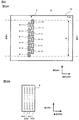
図2は、本発明の第1実施形態に係るヘッドの配置及び構成を説明する図である。図2Aは、ヘッドの配置を示すプリンター3の上面図であり、図2Bは、ヘッドの上面図である。なお、図2A、図2Bにおいては、各ノズルについては、上面から透視した様子を示している。
FIG. 2 is a diagram illustrating the arrangement and configuration of the head according to the first embodiment of the present invention. FIG. 2A is a top view of the
プリンター3には、図示しない給紙トレイから供給される紙、OHPシート、布等の用紙(画像形成媒体)を搬送するベルト12が備えられている。ベルト12は、図示しないモータにより駆動される。ベルト12は、用紙に印刷(画像形成)を行う際には、用紙を搬送方向X、すなわち、上流側(図2A左側)から下流側(図2A右側)に略一定の速度で搬送する。
The
プリンター3においては、複数のサイズの用紙に印刷を行うことができるようになっている。本実施形態では、プリンター3においては、図2Aに示すように幅W(最大印刷可能幅)までの種々のサイズの用紙の印刷が可能である。本実施形態のプリンター3は、用紙のサイズによらず、用紙の幅方向Yの略中心がベルト12の幅方向Yの略中心を搬送されるように構成されている。
The
プリンター3には、複数のヘッド8(8−1〜8−12)が備えられており、これら複数のヘッド8により、幅方向Yの最大印刷可能幅Wの全体に亘って所定の解像度によりインクを噴射できるようになっている。なお、最大印刷可能幅Wの全体に亘って印刷できるように構成されているヘッド8の組をヘッド列ということとする。
The
ヘッド8は、図2Bに示すように、画像形成材の一例としてのインクを噴射する複数のノズル(ノズル群:例えば、シアンインク吐出用の複数のノズル80Cと、マゼンタインク吐出用の複数のノズル80Mと、イエローインク吐出用の複数のノズル80Yと、ブラックインク吐出用の複数のノズル80K)が、用紙が搬送される側(図面奥行き方向)に向けて設けられている。本実施形態では、ヘッド8には、例えば、幅方向Yに複数個(例えば、180個)のシアンインクのノズル80Cが並んだシアン用のノズル列と、複数個のノズル80Mが並んだマゼンタ用のノズル列と、複数個のノズル80Yが並んだイエロー用のノズル列と、複数個のノズル80Kが並んだブラック用のノズル列とが、搬送方向Xに並んで形成されている。ヘッド8においては、各ノズル(80C、80M、80Y、80K)に対応するように、供給される駆動信号に応じて伸縮する図示しない圧電振動子が設けられており、圧電振動子の伸縮を制御することにより、各ノズルからのインクの吐出を制御できるようになっている。
As shown in FIG. 2B, the
ヘッド列9は、図2Aに示すように、複数のヘッド8が幅方向Yに対して千鳥状(互い違い)に並ぶようになっている。ヘッド列9の上流側に配置された複数のヘッド8(8−1、8−3、8−5、8−7、8−9、8−11)は、所定の間隔をあけて幅方向Yに沿って配列されている。下流側に配置された複数のヘッド8(8−2、8−4、8−6、8−8、8−10、8−12)のそれぞれは、最大印刷可能幅において上流側のヘッド8によって印刷できない部分(例えば、各ヘッド8の間)の印刷を補うように配置されている。このように、複数のヘッド8を配置することによって、幅方向Yの最大印刷可能幅Wの全体に亘って所定の解像度によりインクを噴射できるようになっている。
As shown in FIG. 2A, the
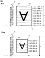
図3は、本発明の第1実施形態に係る画像データ及び各ヘッドの制御に用いられる画像データを説明する図である。図3Aは、最大印刷可能幅Wの画像の画像データを説明する図であり、図3Bは、最大印刷可能幅Wより短い幅の画像の画像データを説明する図である。 FIG. 3 is a diagram illustrating image data and image data used for controlling each head according to the first embodiment of the present invention. FIG. 3A is a diagram illustrating image data of an image having a maximum printable width W, and FIG. 3B is a diagram illustrating image data of an image having a width shorter than the maximum printable width W.
図3Aに示すように、印刷する画像が最大印刷可能幅Wの画像である場合には、転送部5は、形成する画像の色毎の画像データGCについて、最先に印刷される画像の角に位置する画素GSに対応する画素データから搬送方向Xの逆向きの順で各画素に対応する画素データを1ライン分読出し、次に、画素GSの横(図面上側)のラインについて同様に画素データを読み出すようにして、各ラインについての画素データを読み出す処理を繰り返し実行することにより、画素GEに対応する画素データまで読み出し、読み出した画像データをプリンター3に送信する。この画像データは、それぞれの画素の幅方向Yの位置を担当するヘッド8の制御に利用され、本実施形態では、読み出した順に、ヘッド8−1用データ〜ヘッド8−12用データとなっている。
As shown in FIG. 3A, when the image to be printed is an image having the maximum printable width W, the
また、図3Bに示すように、印刷する画像が最大印刷可能幅Wよりも短い幅の画像である場合には、転送部5は、形成する画像の色毎の画像データGCについて、最先に印刷される画像の角に位置する画素GSに対応する画素データから搬送方向Xの逆向きの順で各画素に対応する画素データを1ライン分読出し、次に、画素GSの横(図面上側)のラインについて同様に画素データを読み出すようにして、各ラインについての画素データを読み出す処理を繰り返し実行することにより、画素GEに対応する画素データまで読み出し、読み出した画像データをプリンター3に送信する。この画像データは、それぞれの画素の幅方向Yの位置を担当するヘッド8の制御に利用され、本実施形態では、例えば、読み出した順に、ヘッド8−3用データ〜ヘッド8−10用データとなっている。
Further, as shown in FIG. 3B, when the image to be printed is an image having a width shorter than the maximum printable width W, the
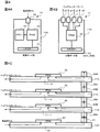
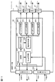
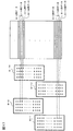
図4は、本発明の第1実施形態に係る分配部のハードウエア構成図である。図4Aは、受信ボード部10の構成を示し、図4Bは、分配ボード部11の構成を示し、図4Cは、受信ボード部10と分配ボード部11との接続状態を示す図である。
FIG. 4 is a hardware configuration diagram of the distribution unit according to the first embodiment of the present invention. 4A shows a configuration of the receiving
受信ボード部10においては、図4Aに示すように、ボード10A上に、複数の分配ボード部11の内の最上位の分配ボード部11−1と通信可能に接続するためのオスのコネクター21と、各種処理を実行するFPGA(Field Programmable Gate Array)22と、メモリー23と、転送部5との間の通信線を接続するためのスロット24とが配置されている。ここで、分配ボード部11の上位とは、通信に関して受信ボード部10側にあることを意味している。
In the receiving
分配ボード部11においては、図4Bに示すように、ボード11A上に、上位の部位(受信ボード部10又は分配ボード部11)と通信可能に接続するためのメスのコネクター25Aと、下位の分配ボード部11と通信可能に接続するためのオスのコネクター25Bと、各種処理を実行するFPGA26と、複数のヘッドコントローラー7との間の通信線を接続するための複数(例えば、4個)のスロット27とが配置されている。本実施形態では、スロット27に対して1つのヘッドコントローラー7が接続可能である。コネクター25Aと、コネクター25Bとは、図4Cに示すように、ボード11Aに対して略対称な位置に配置されている。このようにコネクター25A及びコネクター25Bを配置しているので、各分配ボード部11を同一の形状とすることができる。これにより、各分配ボード部11の製造コストを低減することができる。
In the
分配部6においては、図4Cに示すように、受信ボード部10のオスのコネクター21と、最上位の分配ボード部11−1のメスのコネクター25Aとが接続され、分配ボード部11−1のオスのコネクター25Bと、分配ボード部11−2のメスのコネクター25Aとが接続され、分配ボード部11−2のオスのコネクター25Bと、本実施形態では、最下位となる分配ボード部11−3のメスのコネクター25Aとが接続されている。
In the
本実施形態では、図4Cに示すように、転送部5と受信ボード部10のFPGA22との間で通信できるようになっている。また、受信ボード部10のFPGA22と、最上位の分配ボード部11−1のFPGA26とが、コネクター21及びコネクター25Aを介して通信できるようになっている。また、分配ボード部11−1のFPGA26と、下位の分配ボード部11−2のFPGA26とが、コネクター25B及びコネクター25Aを介して通信できるようになっている。また、分配ボード部11−2のFPGA26と、下位の分配ボード部11−3のFPGA26とが、コネクター25B及びコネクター25Aを介して通信できるようになっている。
In the present embodiment, as shown in FIG. 4C, communication can be performed between the
図5は、本発明の第1実施形態に係る分配部の信号線を説明する図である。 FIG. 5 is a diagram illustrating signal lines of the distribution unit according to the first embodiment of the present invention.
分配部6においては、受信ボード部10と、複数の分配ボード部11−1〜11−3とがカスケード接続されている。すなわち、受信ボード部10と、分配ボード部11−1との間は、データバスと、アドレスバスと、後述するValid信号を送信するためのValid信号線と、後述するBusy(ビジー)信号を送信するためのBusy信号線とが接続されている。また、分配ボード部11−1と、分配ボード部11−2との間は、データバスと、アドレスバスと、Valid信号線と、Busy信号線とが接続されている。また、分配ボード部11−2と、分配ボード部11−3との間は、データバスと、アドレスバスと、Valid信号線と、Busy信号線とが接続されている。
In the
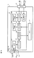
図6は、本発明の第1実施形態に係る受信ボード部の機能構成図である。 FIG. 6 is a functional configuration diagram of the receiving board unit according to the first embodiment of the present invention.
受信ボード部10のFPGA22には、受信部22Aと、データ格納処理部22Bと、読出アドレス生成部22Cと、画像データ読出手段の一例としてのデータ読出処理部22Dと、転送先決定手段の一例としての転送先アドレス生成部22Eと、データ送信手段の一例としてのデータ転送部22Fと、状態情報受信手段の一例としてのBusy管理部22Gとが構築されている。
The
受信部22Aは、転送部5から送信される画像データを受信し、受信した画像データを逐次データ格納処理部22Bに渡す。データ格納処理部22Bは、受信部22Aから受け取った画像データをメモリー23に格納する。本実施形態では、データ格納処理部22Bは、受信部Aから受け取った画像データを連続して格納する。
The receiving
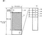
図7は、本発明の第1実施形態に係るメモリー内の領域を説明する図である。 FIG. 7 is a diagram for explaining an area in the memory according to the first embodiment of the present invention.
データ格納処理部22Bは、図7に示すように、メモリー23のメモリー空間を複数のメモリーブロックMBに分け、1つのメモリーブロックMBに1ページ分の画像の1色の画像データを格納する。例えば、印刷用の画像データがCMYKの4色の画像データで構成されている場合には、データ格納処理部22Bは、1ページ分のシアンの画像データ、1ページ分のマゼンタの画像データ、1ページ分のイエローの画像データ、1ページ分のブラックの画像データのそれぞれを1つのメモリーブロックMBに格納する。なお、メモリー23のメモリー空間に余裕があれば、他のページの画像データも格納される。
As shown in FIG. 7, the data
メモリーブロックMBは、画像データを構成する画素データを記憶することのできるライン数が、最大印刷可能幅Wの1色の印刷を担当する全ノズル数となっており、また、各ラインのサイズとしては、転送される画像データのラインサイズ(画像を構成する搬送方向の画素数)の画素データを格納できるサイズとなっており、最大印刷可能幅Wの画像の1色の画像データが格納できるようになっている。なお、転送される画像データのラインサイズや、幅方向のライン数等の情報は、画像データが転送される前に、転送部5から予め送信されている。
In the memory block MB, the number of lines that can store the pixel data constituting the image data is the total number of nozzles in charge of printing one color of the maximum printable width W, and the size of each line Is a size that can store pixel data of the line size of the image data to be transferred (the number of pixels in the transport direction constituting the image), so that one color image data of an image with the maximum printable width W can be stored. It has become. Information such as the line size of the image data to be transferred and the number of lines in the width direction is transmitted from the
例えば、図3Bに示すような最大印刷可能幅Wよりも小さい幅の画像データである場合には、データ格納処理部22Bは、図7に示すように、印刷時にインクを吐出しないノズル用のデータを格納する領域(格納開始オフセット)を空けて、画像データGCが格納される。画像データGCは、最先に印刷される画像の角に位置する画素GSに対応する画素データが領域の左上に格納され、画素GEに対応する画素データが領域の右下に格納される。この画像データGCの格納されているラインの総数は、画像の実ライン数となっている。
For example, in the case of image data having a width smaller than the maximum printable width W as shown in FIG. 3B, the data
図8は、本発明の第1実施形態に係るメモリーブロックの状態及び画像データの転送を説明する図である。図8Aは、メモリーブロックに格納されている画像データと送信すべきヘッドコントローラーとの対応関係を示し、図8Bは、画像データの各ラインの転送順番を示している。 FIG. 8 is a diagram for explaining the state of the memory block and image data transfer according to the first embodiment of the present invention. FIG. 8A shows the correspondence between the image data stored in the memory block and the head controller to be transmitted, and FIG. 8B shows the transfer order of each line of the image data.
画像データが格納されたメモリーブロックMBにおいては、図8Aに示すように、最も上の領域から順に、ヘッドコントローラー7−1に転送する画像データ(ヘッド8−1用の画像データ)が格納され、ヘッドコントローラー7−2に転送する画像データ(ヘッド8−2用の画像データ)が格納され、ヘッドコントローラー7−3に転送する画像データ(ヘッド8−3用の画像データ)が格納され、ヘッドコントローラー7−4に転送する画像データ(ヘッド8−4用の画像データ)が格納され、以降、ヘッドコントローラー7−5(ヘッド8−5用の画像データ)に転送する画像データからヘッドコントローラー7−12に転送する画像データ(ヘッド8−12用の画像データ)まで格納される。なお、最大印刷可能幅Wよりも小さい幅の画像の画像データである場合には、図8Aに示すように、最も上の領域と、最も下の領域には、予めメモリーブロックMBに格納されているインクの吐出がないことを示すNULL値が設定されている。 In the memory block MB in which the image data is stored, as shown in FIG. 8A, image data (image data for the head 8-1) to be transferred to the head controller 7-1 is stored in order from the uppermost area. Image data to be transferred to the head controller 7-2 (image data for the head 8-2) is stored, and image data to be transferred to the head controller 7-3 (image data for the head 8-3) is stored. The image data to be transferred to the head 7-4 (image data for the head 8-4) is stored. Thereafter, the image data to be transferred to the head controller 7-5 (the image data for the head 8-5) is transferred to the head controller 7-12. Up to the image data to be transferred (image data for the head 8-12). When the image data is an image having a width smaller than the maximum printable width W, the uppermost area and the lowermost area are stored in advance in the memory block MB as shown in FIG. 8A. A NULL value indicating that no ink is ejected is set.
読出アドレス生成部22Cは、予め設定された情報に基づいて、データを読み出すべきメモリー23のアドレスを生成してデータ読出処理部22Dに通知する。なお、実際の画像データがメモリーブロックMBの一部に格納されている場合であっても、メモリーブロックMBの全てのデータを読み出すようにアドレスを生成している。
The read
ここで、転送部5から受信ボード部10に画像データを転送し、メモリー23に格納する速度と、メモリー23から画像データを読み出す速度とに比べて、分配ボード部11がヘッドコントローラー7に画像データを転送する速度が遅い。このため、同一のヘッドコントローラー7に送信する画像データを連続して送信すると、分配ボード部11が同一のヘッドコントローラー7に送信する速度の影響により、全てのヘッドコントローラー7への画像データを送信し終えるまで長時間を要してしまうこととなる。
Here, the
そこで、本実施形態では、読出アドレス生成部22Cは、所定のN(1以上の整数)ライン毎に異なるヘッドコントローラー7への画像データが転送できるようにするために、Nライン毎に異なるヘッドコントローラー7への画像データが格納されているアドレスを生成するようにしている。
Therefore, in the present embodiment, the read
例えば、1ライン毎に異なるヘッドコントローラー7へ画像データが転送されるようにする場合には、図8Bに示すような順番でアドレスを生成する。すなわち、読出アドレス生成部22Cは、ヘッドコントローラー7−1に転送するデータである、1番のラインの画像データLを示すアドレスを生成し、次に、ヘッドコントローラー7−2に転送するデータである2番のラインの画像データLを示すアドレスを生成するようにし、同様にして、各ヘッドコントローラー7−3〜7−11に転送するデータを示すアドレスを生成し、ヘッドコントローラー7−12に転送するデータである12番のラインの画像データLを示すアドレスを生成した後に、再び、ヘッドコントローラー7−1に転送するデータを示すアドレスを生成するようにして、メモリーブロックMB内の全てのデータが読み出されるようにアドレスを生成する。このようにして、例えば、ヘッドコントローラー7−1に転送するデータのアドレスは、1番目、13番目、25番目、37番目・・・に生成され、ヘッドコントローラー7−2に転送するデータのアドレスは、2番目、14番目、26番目、38番目・・・に生成され、ヘッドコントローラー7−12に転送するデータのアドレスは、12番目、24番目、36番目、48番目・・・に生成されることとなる。
For example, when image data is transferred to a
データ読出処理部22Dは、読出アドレス生成部22Cにより生成されたアドレスに対応するデータをメモリー23から読み出す。本実施形態では、データ読出処理部22Dは、アドレスに対応する1ラインのデータを単位として、Nライン分読み出し、データ転送部22Fに送信する。
The data read
次に、読出アドレス生成部22Cが各ヘッドコントローラー7に送る画像データの単位となるライン数Nを決定する処理について説明する。
Next, a process for determining the number N of lines as a unit of image data sent from the read
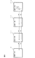
図9は、本発明の第1実施形態に係るビジー信号のレイテンシーを説明する図である。 FIG. 9 is a diagram illustrating the latency of the busy signal according to the first embodiment of the present invention.
本実施形態では、後述するように、一の転送先に画像データを転送している際に、並行して、次の転送先となるヘッドコントローラーを担当する(に接続されている)分配ボード部11からの画像データの受入可能か否かを示すビジー信号の受信を行うようにしている。このため、次の転送先となるヘッドコントローラー7を担当する分配ボード部11から画像データを受入可能であるとのビジー信号を受け取る前には、次の転送先へ画像データを転送することができない。
In this embodiment, as will be described later, when image data is transferred to one transfer destination, a distribution board unit in charge of (connected to) the head controller that is the next transfer destination in parallel A busy signal indicating whether or not image data from 11 can be received is received. For this reason, the image data cannot be transferred to the next transfer destination before receiving a busy signal indicating that the image data can be received from the
このような場合に、一の転送先の画像データの転送が終わってしまうと、いずれの画像データも転送されていない状態となり、データ転送効率が低下してしまう。 In such a case, when the transfer of the image data of one transfer destination is finished, no image data is transferred, and the data transfer efficiency is lowered.
そこで、本実施形態では、転送先からのビジー信号を受信するまでの時間において、画像データを転送しておくことができるようにするために、1つのヘッドコントローラー7に送信する画像データのライン数を調整するようにしている。
Therefore, in the present embodiment, the number of lines of image data to be transmitted to one
ここで、ビジー信号に関わるレイテンシ(遅延)としては、以下の5種類がある。 Here, there are the following five types of latency (delay) related to the busy signal.
すなわち、受信ボード部10から出力したアドレスデータ(次転送先アドレス)を分配ボード部11−1がラッチするまでの時間TAと、アドレスデータをラッチしてから次(下位)の分配ボード部11がラッチするまでの時間TBと、アドレスデータをラッチしてから、分配ボード部11において画像データを受入可能か否かのビジー判定をし、前(上位)の分配ボード部11に返信する準備ができるまでの時間TCと、ビジー信号を出力してから前の分配ボード部11が更に前の分配ボード部11に返す準備ができるまでの時間TDと、分配ボード部11−1からビジー信号を受信ボード部10に送信して、受信ボード部10がビジー信号の判定をできるまでの時間TEとがある。
That is, the time TA until the distribution board unit 11-1 latches the address data (next transfer destination address) output from the receiving
本実施形態では、画像データのライン数の調整については、クリティカルパス、すなわち、最下位の分配ボード11−3からのビジー信号が戻ってくる経路を基準に判断するようにしている。 In the present embodiment, the adjustment of the number of lines of image data is determined based on a critical path, that is, a path on which a busy signal from the lowest distribution board 11-3 returns.
最下位の分配ボード11−3からビジー信号が戻ってくるまでのレイテンシーTLは、次式で表される。 The latency TL until the busy signal returns from the lowest distribution board 11-3 is expressed by the following equation.
TL=TA+TE+TC+(TB+TD)×(分配ボード部11の接続数−1)
ここで、TA、TB、TC、TD、TE、TLの単位は、それぞれ基準クロックのクロック数であり、各値は、予め測定されて読出アドレス生成部22Cに記憶されている。
TL = TA + TE + TC + (TB + TD) × (number of connections of
Here, the unit of TA, TB, TC, TD, TE, and TL is the number of clocks of the reference clock, and each value is measured in advance and stored in the read
本実施形態では、このようなレイテンシーTL以上の転送時間を要するデータ量を単位として各転送先に送信するようにしている。例えば、1画素のデータを1ビットとすると、TL×データバス幅(ビット/1クロック)≦1ラインサイズ×Nとなるようなライン数Nを各転送先に送信するデータの単位として決定している。このようにすることにより、ビジー信号を受信する前における、データを転送しない時間の発生を低減することができる。 In the present embodiment, such a data amount that requires a transfer time equal to or higher than the latency TL is transmitted to each transfer destination as a unit. For example, if 1 pixel data is 1 bit, the number of lines N such that TL × data bus width (bit / 1 clock) ≦ 1 line size × N is determined as a unit of data to be transmitted to each transfer destination. Yes. By doing so, it is possible to reduce the occurrence of time during which data is not transferred before the busy signal is received.
転送先アドレス生成部22Eは、データ読出処理部22Dにより読み出された画像データの転送先となるヘッドコントローラー7を示すアドレス(転送先アドレス:転送先識別情報)を生成し、データ転送部22Fに出力する。なお、転送先となるヘッドコントローラー7は、読出アドレス生成部22Cの生成するメモリー23のアドレスに対応するデータを転送すべきヘッドコントローラー7であって、プリンター3のヘッド8の配置、構成及び読出アドレス生成部22Cのアドレスを生成する規則に従って、決定することができる。ヘッドコントローラー7は、いずれかのスロット27に接続されているので、本実施形態では、ヘッドコントローラー7のアドレスとして、当該ヘッドコントローラー7へ接続されるスロット27の識別情報(スロットID)と、そのスロット27を有する分配ボード部11の識別情報(分配ボード部ID)とを用いている。また、本実施形態では、ヘッドコントローラー接続情報を参照することにより、画像データを転送すべきヘッドコントローラー7の接続されているスロット27を特定し、対応する転送先アドレスを生成するようにしている。このため、分配ボード部11において、ヘッドコントローラー7が接続されていないスロット27があっても問題がない。例えば、いずれかの分配ボード部11にヘッドコントローラー7が接続されていない予備のスロット27を確保しておき、いずれかのスロット27が故障した場合に、予備のスロット27を用いてヘッドコントローラー7の接続を行い、以降において当該スロット27のアドレスを指定することにより、ヘッドコントローラー7に画像データを適切に転送することができる。また、新たな分配ボード部11を分配ボード部11−3の下位に接続するようにして、新たに追加した分配ボード部11のスロット27を用いてヘッドコントローラー7を接続するようにすることもでき、例えば、この場合における接続状態に対応する接続情報を受け取っておくことで、ヘッドコントローラー7が接続されたスロット27のアドレスを指定して適切に画像データを所望のヘッドコントローラー7に送信することができる。
The transfer destination
また、転送先アドレス生成部22Eは、次の転送先となるヘッドコントローラー7のアドレス(次転送先アドレス:次転送先識別情報)を生成し、データ転送部22Fに出力する。
Further, the transfer destination
本実施形態では、次のように転送先アドレスを管理している。 In the present embodiment, the transfer destination address is managed as follows.
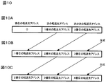
図10は、本発明の第1実施形態に係る転送先アドレスの管理を説明する図である。 FIG. 10 is a diagram for explaining the management of transfer destination addresses according to the first embodiment of the present invention.
転送先アドレス生成部22Eは、3つのレジスターで構成されるシフトレジスターを内部に備えている。シフトレジスターの左側のレジスターは、現在の転送先アドレスを格納し、中央のレジスターは、次の転送先アドレスを格納し、右側のレジスターは、次の次の転送先アドレスを格納する。このシフトレジスターは、各レジスターのデータを左のレジスターに移動(シフト)することができるようになっている。
The transfer destination
転送先アドレス生成部22Eは、画像データの転送を開始する際において、図10Aに示すように、画像データを転送する1番目の転送先アドレスを生成して中央のレジスターに格納し、次に画像データを転送する2番目の転送先アドレスを生成して右側のレジスターに格納する。そして、転送先アドレス生成部22Eは、左側のレジスターの値(初期値0)を現在の転送先アドレスとして、中央のレジスターの値(2番目の転送先アドレス)を次の転送先アドレスとしてデータ転送部22Fに送信する。これにより、1番目の転送先アドレスに対応する転送先についてのビジー信号の確認が行なわれることとなる。
When starting transfer of image data, the transfer destination
次いで、図10Bに示すように、転送先アドレス生成部22Eは、シフトレジスターの値を左にシフトさせ、次の次の転送先アドレス(3番目の転送先アドレス)を生成して右側のレジスターに格納し、左側のレジスターの値(1番目の転送先アドレス)を現在の転送先アドレスとして、中央のレジスターの値(2番目の転送先アドレス)を次転送先アドレスとしてデータ転送部22Fに送信する。これにより、1番目の転送先への画像データの転送が行なわれ、2番目の転送先についてのビジー信号の確認が行なわれる。
Next, as illustrated in FIG. 10B, the transfer destination
次いで、図10Cに示すように、転送先アドレス生成部22Eは、シフトレジスターの値を左にシフトさせ、次の次の転送先アドレスを生成して右側のレジスターに格納し、左側のレジスターの値を現在の転送先アドレスとして、中央のレジスターの値を次の転送先アドレスとしてデータ転送部22Fに送信する。以降は、転送先アドレス生成部22Eは、この処理を繰り返し実行する。
Next, as illustrated in FIG. 10C, the transfer destination
データ転送部22Fは、FIFO(First In First Out)又はダブルバッファ構造の内部メモリー(一時記憶部)を有しており、データ読出処理部22Dからの画像データを一時的に格納する。
The
データ転送部22Fは、Busy管理部22Gから転送を開始する転送先が画像データを受入可能であるとの通知を受け取った場合に、内部メモリーの対応する転送先への画像データと、当該データの転送先として受け取った転送先アドレスと、次の転送先として受け取った次転送先アドレスとをコネクター21を介して分配ボード部11−1に送信する。なお、本実施形態では、分配ボード部11−1に、画像データと、転送先アドレスと、次転送先アドレスとを送信すると、下位の分配ボード部11−2、11−3までこれらデータが送信される。本実施形態では、データ転送部22Fは、FPGA22が発生する1クロックに合わせて、転送対象の画像データの1クロック分のデータをデータバスにより送信し、また、転送先アドレス及び次転送先アドレスをアドレスバスにより送信する。なお、このように、1クロック分のデータと、転送先アドレスとを、1クロックに合わせて送信するようにしているので、例えば、1クロック毎に転送先アドレスを替えて送信することもできる。また、データ転送部22Fは、画像データを送信する際には、送信している画像データが有効であることを示す信号、すなわちH(ハイ)状態のValid信号を送信する。
When the
Busy管理部22Gは、分配ボード部11−1から送信されるビジー信号に基づいて、次の転送先がデータの受入可能であるか否かを判定し、その結果をデータ転送部22Fに通知する。本実施形態では、転送先がデータ受入可能な場合には、ビジー信号はH(ハイ)状態にされ、転送先がデータ受入可能でない場合には、ビジー信号はL(ロー)状態にされるようになっている。
The
図11は、本発明の第1実施形態に係る分配ボード部の機能構成図である。 FIG. 11 is a functional configuration diagram of the distribution board unit according to the first embodiment of the present invention.
分配ボード部11のFPGA26には、受信手段及び下位送信手段の一例としての受信部26Aと、Busy判定部26Bと、自身データ判定部26Cと、転送先判定部26Dと、複数のヘッドコン転送部(配信手段)26Eとが構築されている。
The
受信部26Aは、上位側のコネクター25Aから送信されるクロック、画像データ、転送先アドレス、次転送先アドレス、及びValid信号を受信する。また、受信部26Aは、Valid信号がデータが有効であることを示している場合(Valid信号がH状態である場合)には、画像データと、転送先アドレスとを自身データ判定部26Cに渡し、Valid信号がデータが有効でないことを示している場合(Valid信号がL状態である場合)には、画像データ、転送先アドレスを破棄する。また、受信部26Aは、次転送先アドレスをBusy判定部26Bに渡す。また、受信部26Aは、自身の分配ボード部11で生成したクロックを下位の分配ボード部11に送信するとともに、当該クロックに合わせて、受信した画像データ、転送先アドレス、及び次転送先アドレスを送信し、また、Valid信号も送信する。ここで、分配ボード部11が自身で生成したクロックに合わせて、画像データ、転送先アドレス、及び次転送先アドレスを送信するので、当該分配ボード部11に送信された際に発生していたクロックと各データとのずれを排除して下位の分配ボード部11に送信することができる。従って、下位の分配ボード部11においては、適切に各データを受信することができる。
The receiving
自身データ判定部26Cは、受信部26Aから受け取った転送先アドレスが、自身の分配ボード部11に接続されたヘッドコントローラー7を示している否かを判定する。ここで、自身の分配ボード部11に接続されたヘッドコントローラー7を示している否かは、転送先アドレスに自身の識別情報(分配ボード部ID)が格納されているか否かにより判定することができる。ここで、分配ボード部11自身の識別情報は、例えば、図示しないディップスイッチによって設定されている。また、自身データ判定部26Cは、自身の分配ボード部11に接続されたヘッドコントローラー7を示していると判定した場合には、受信部26Aから受けとった画像データと、転送先アドレスとを転送先判定部26Dに渡す一方、自身の分配ボード部11に接続されたヘッドコントローラー7を示していないと判定した場合には、画像データ、転送先アドレスを破棄する。
The own data determination unit 26C determines whether or not the transfer destination address received from the
転送先判定部26Dは、自身データ判定部26Cから受け取った転送先アドレスから、送信すべきスロット27を特定する。本実施形態では、転送先アドレスの内のスロット27のIDによりスロット27を特定することができる。転送先判定部26Dは、特定したスロット27に接続されているヘッドコン転送部26Eに画像データを送信する。
The transfer
ヘッドコン転送部26Eは、ヘッドコントローラー7に送信する画像データを一時的に記憶するためのFIFOの内部メモリーを有している。ヘッドコン転送部26Eは、転送先判定部26Dから送信された画像データを内部メモリーに格納し、内部メモリーから画像データを取り出して、スロット27を介してヘッドコントローラー7に画像データを送信する。また、ヘッドコン転送部26Eは、FIFOの内部メモリーに格納されている画像データの記憶量が所定の閾値を超えた場合には、画像データを受入不可能であることを示す信号(H状態のビジー信号)をBusy判定部26Bに出力し、それ以外の場合には、画像データを受入可能であることを示す信号(H状態のビジー信号)をBusy判定部26Bに送信する。閾値としては、例えば、送信単位であるNライン分の画像データを格納する容量が残されていない場合における記憶量であってもよい。
The head
Busy判定部26Bは、受信部26Aから受け取った次転送先アドレスが自身の分配ボード部11に接続されたヘッドコントローラー7を示している否かを判定する。Busy判定部26Bは、次転送先アドレスが自身の分配ボード部11に接続されたヘッドコントローラー7を示している場合には、次転送先アドレスに対応するスロット27に接続されているヘッドコン転送部26Eを特定し、当該ヘッドコン転送部26Eから送信されるビジー信号を選択して、上位の部位(受信ボード部10又は分配ボード部11)に送信する。一方、Busy判定部26Bは、次転送先アドレスが自身の分配ボード部11に接続されたヘッドコントローラー7を示していない場合には、下位の部位(分配ボード部11)から送信されているビジー信号を受け取り、上位の部位(受信ボード部10又は分配ボード部11)に送信する。
The
次に、プリンター3の受信ボード部10による画像データの送信処理について説明する。
Next, image data transmission processing by the receiving
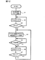
図12は、本発明の第1実施形態に係る受信ボード部による画像データの送信処理のフローチャートである。 FIG. 12 is a flowchart of image data transmission processing by the reception board unit according to the first embodiment of the present invention.
この画像データの送信処理は、受信ボード部10の受信部22Aが転送部5から画像データを受信し、データ格納処理部22Bがメモリー23に画像データを格納した後に開始される。
The image data transmission process is started after the receiving
まず、転送先アドレス生成部22Eが画像データを最初に送信する転送先のヘッドコントローラー7を示す転送先アドレスを次転送先アドレスとして、データ転送部22Fに渡す。データ転送部22Fは、次転送先アドレスを、コネクター21を介して分配ボード部11−1に送信する(ステップS1)。これによって、分配ボード部11−1から次転送先アドレスに対応する分配ボード部11から画像データが受入可能か否かを示すビジー信号が戻ってくることとなる。
First, the transfer destination
これと並行して、読出アドレス生成部22Cは、次に転送する画像データを読み出すメモリー23のアドレスを生成して、データ読出し処理部22Dに渡す。データ読出処理部22Dは、渡されたアドレスに格納されている画像データをメモリー23から読み出して、データ転送部22Fに渡す。これにより、データ転送部22Fに画像データが格納されることとなる。一方、転送先アドレス生成部22Eは、画像データを転送する転送先アドレスと、その次の画像データを転送する次転送先アドレスとを生成し、データ転送部22Fに出力する。
In parallel with this, the read
Busy管理部22Gは、コネクター21を介して受信したビジー信号をチェックし(ステップS2)、ビジー信号が受入不可能であること(ビジーであること)を示している場合(ステップS3:YES)には、ステップS2に戻る。一方、ビジー信号が受入不可能でないことを示している場合(ステップS3:NO)には、その旨をデータ転送部22Fに通知する。
The
データ転送部22Fは、内部メモリーに記憶している画像データと、転送先アドレスと、次転送先アドレスとを分配ボード部11−1に送信するとともに、Valid信号をH状態にして送信する(ステップS4)。これによって、分配ボード部11−1から次転送先アドレスに対応する分配ボード部11から画像データが受入可能か否かを示すビジー信号が戻ってくることとなる。
The
これと並行して、読出アドレス生成部22Cは、次に転送する画像データを読み出すメモリー23のアドレスを生成して、データ読出処理部22Dに渡す。データ読出処理部22Dは、渡されたアドレスに格納されている画像データをメモリー23から読み出して、データ転送部22Fに渡す。これにより、データ転送部22Fの内部メモリーに画像データが格納されることとなる。一方、転送先アドレス生成部22Eは、画像データを転送する転送先アドレスと、その次の画像データを転送する次転送先アドレスとを生成し、データ転送部22Fに出力する。
In parallel with this, the
データ転送部22Fは、ステップS4のデータ送信が完了したか否かを判断し(ステップS5)、データ送信が完了していない場合(ステップS5:NO)には、データ送信が完了するまで待つ。
The
一方、データ送信が完了した場合(ステップS5:YES)には、Busy管理部22Gは、コネクター21を介して受信したビジー信号をチェックし(ステップS6)、ビジー信号が受入不可能であること(ビジーであること)を示している場合(ステップS7:YES)には、ステップS6に戻る。一方、ビジー信号が受入不可能でないことを示している場合(ステップS7:NO)には、その旨をデータ転送部22Fに通知する。これにより、ステップS4以降の処理が実行されることとなり、次の順番の転送先への画像データが送信されることとなる。
On the other hand, when the data transmission is completed (step S5: YES), the
次に、上記した画像データの送信処理の具体的な例を、図13を参照して説明する。 Next, a specific example of the above-described image data transmission process will be described with reference to FIG.
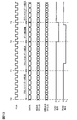
図13は、本発明の第1実施形態に係る画像データの送信に関わる各種信号のタイミングチャートである。 FIG. 13 is a timing chart of various signals related to transmission of image data according to the first embodiment of the present invention.
図12のステップS3で最初の転送先が受入可能であると判定された場合には、データ転送部22Fは、図14の時刻T0以降に示すように、クロック信号CLKの各クロックに合わせて、転送先”1”(最初の転送先)への画像データの1クロック分のデータDATAと、転送先アドレス(”1”)と、次の転送先アドレス(”2”)とを繰り返して送信し、また、Valid信号をH状態として送信する。
When it is determined in step S3 in FIG. 12 that the first transfer destination is acceptable, the
この転送先”1”への画像データの送信が完了する前までには、次の転送先”2”からのビジー信号が戻ってくる。ここで、転送先”1”への画像データの送信が完了した時刻T1においては、ビジー信号がH状態であるので、次の転送先”2”は、画像データの受入が可能であることを示している。 Before the transmission of the image data to the transfer destination “1” is completed, the busy signal from the next transfer destination “2” is returned. Here, since the busy signal is in the H state at the time T1 when the transmission of the image data to the transfer destination “1” is completed, the next transfer destination “2” can accept the image data. Show.
転送先”1”への画像データの送信が完了した後に、データ転送部22Fは、時刻T1以降に示すように、クロック信号CLKの各クロックに合わせて、転送先”2”への画像データの1クロック分のデータDATAと、転送先アドレス(”2”)と、次の転送先アドレス(”3”)とを繰り返して送信し、また、Valid信号をH状態として送信する。
After the transmission of the image data to the transfer destination “1” is completed, the
この転送先”2”への画像データの送信が完了する前までには、次の転送先”3”からのビジー信号が戻ってくる。ここで、時刻T2よりも前において、ビジー信号がL状態となっているので、次の転送先”3”は、画像データの受入が不可能であることを示している。 Before the transmission of the image data to the transfer destination “2” is completed, the busy signal from the next transfer destination “3” is returned. Here, since the busy signal is in the L state before the time T2, the next transfer destination “3” indicates that the image data cannot be received.
転送先”2”への画像データの送信が完了した時刻T2においても、ビジー信号がL状態のままであり、次の転送先”3”は、画像データの受入が不可能であることを示しているので、データ転送部22Fは、転送先”3”への画像データの転送を行なわない。なお、この場合には、データ転送部22Fは、クロック信号CLKの各クロックに合わせて、転送先アドレス(”2”)と、次の転送先アドレス(”3”)とを送信し、また、Valid信号をデータが有効でないことを示すL状態として送信する。
Even at time T2 when the transmission of the image data to the transfer destination “2” is completed, the busy signal remains in the L state, and the next transfer destination “3” indicates that the image data cannot be received. Therefore, the
そして、ビジー信号がH状態に変わったときは、次の転送先”3”は、画像データの受入が可能であることを示しているので、その後の時刻T3以降に示すように、データ転送部22Fは、クロック信号CLKの各クロックに合わせて、転送先”3”への画像データの1クロック分のデータDATAと、転送先アドレス(”3”)と、次の転送先アドレス(”4”)とを繰り返して送信し、また、Valid信号をH状態として送信する。
When the busy signal is changed to the H state, the next transfer destination “3” indicates that the image data can be received. Therefore, as shown after the time T3, the
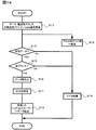
図14は、本発明の第1実施形態に係る分配ボード部による画像データの受信処理のフローチャートである。 FIG. 14 is a flowchart of image data reception processing by the distribution board unit according to the first embodiment of the present invention.
分配ボード部11の受信部26Aは、上記の部位(受信ボード部10又は上位の分配ボード部11)からデータ、転送先アドレス、次転送先アドレス、及びValid信号を受信する(ステップS11)。
The receiving
受信部26Aは、下位の分配ボード部11があれば、下位の分配ボード部11に対して、自身のクロックに合わせて、受信したデータ、転送先アドレス及び次転送先アドレスを転送するとともに、受信したValid信号を転送する(ステップS12)。
If there is a lower
また、これと並行して、受信部26Aは、Valid信号が、データが有効であることを示しているか否かを判定し(ステップS13)、データが有効でない場合には、データを破棄し(ステップS14)、処理を終了する。
In parallel with this, the receiving
一方、Valid信号が、データが有効であることを示している場合(ステップS13:YES)には、データ、転送先アドレスを自身データ判定部26Cに渡す。自身データ判定部26Cは、転送先アドレスが自身の分配ボード部11に接続されたヘッドコントローラー7を示している否か、すなわち、転送先アドレスに自身の分配ボード部11の識別情報が含まれているか否かを判定し(ステップS15)、自身の分配ボード部11の識別情報が含まれていない場合(ステップS15:NO)には、データを破棄し(ステップS14)、処理を終了する。
On the other hand, when the Valid signal indicates that the data is valid (step S13: YES), the data and the transfer destination address are passed to the own data determination unit 26C. The own data determination unit 26C determines whether or not the transfer destination address indicates the
一方、自身の分配ボード部11の識別情報が含まれている場合(ステップS15:YES)には、自身データ判定部26Cは、データと、転送先アドレスとを取り込んで、転送先判定部26Dに渡す(ステップS16)、転送先判定部26Dは、転送先アドレスに対応するヘッドコン転送部26Eを特定し(ステップS17)、特定したヘッドコン転送部26Eに画像データを転送する。ヘッドコン転送部26Eは、スロット27を介して、転送された画像データをヘッドコントローラー7に送信する(ステップS18)。これによって、ヘッドコントローラー7は、画像データに基づいて自身に接続されたヘッド8を制御することとなる。
On the other hand, when the identification information of its own
次に、本発明の第2実施形態に係る画像形成システムについて説明する。 Next, an image forming system according to a second embodiment of the present invention will be described.
図15は、本発明の第2実施形態に係る画像形成システムの構成図である。なお、第1実施形態に係る画像形成システムと同様な部分については同一符号を付すこととする。 FIG. 15 is a configuration diagram of an image forming system according to the second embodiment of the present invention. The same reference numerals are given to the same parts as those in the image forming system according to the first embodiment.
第2実施形態に係るプリンター3は、第1実施形態に係るプリンター3において、複数のヘッド列9−1、9−2を備えるようにしたものであり、それに伴って、ヘッドコントローラー7−13〜7−24と、分配部6−2とを更に備えるようにしたものである。
The
第2実施形態に係る画像形成システム1においては、転送部5と、分配部6−1と、下位の分配部6−2とによってリング型のネットワークが形成されている。すなわち、転送部5と分配部6−1の受信ボード部10とが通信可能に接続され、分配部6−1の受信ボード部10と下位の分配部6−2の受信ボード部10とが通信可能に接続され、分配部6−2の受信ボード部10と転送部5とが通信可能に接続されている。
In the
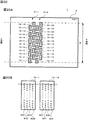
図16は、本発明の第2実施形態に係るヘッドの配置及び構成を説明する図である。図16Aは、ヘッドの配置を示すプリンター3の上面図であり、図16Bは、ヘッドの上面図である。なお、図16A、図16Bにおいては、各ノズルについては、上面から透視した様子を示している。
FIG. 16 is a diagram illustrating the arrangement and configuration of the head according to the second embodiment of the present invention. FIG. 16A is a top view of the
プリンター3においては、複数のヘッド列9−1、9−2が配置されている。ヘッド列9−1、9−2のそれぞれにおけるヘッド8の構成及びヘッド8の配列については、第1実施形態のヘッド列9のヘッド8の構成及びヘッド8の配列とほぼ同様である。
In the
本実施形態においては、ヘッド列9−1の各ヘッド8と、ヘッド列9−2の対応する各ヘッド8(ノズル列内における対応する位置に配置されているヘッド8)とのノズル80C、80M、80Y、80Kの幅方向における配置位置が異なっている。
In the present embodiment, the
すなわち、図16Bに示すように、ノズル列9−1のヘッド8−1におけるノズル80C、80M、80Y、80Kの幅方向における配置位置は、ノズル列9−2の対応するヘッド8−13のノズル80C、80M、80Y、80Kの幅方向における配置位置とは、ノズルピッチの半分だけずれている。このように、2つのヘッド列の対応するヘッド同士のノズルの幅方向の配置位置が、ノズルピッチの半分だけずれているので、2つのヘッド列により画像を形成すると、1つのヘッド列で形成できる画像の倍の解像度の画像を形成することができる。
That is, as shown in FIG. 16B, the arrangement positions of the
図17は、本発明の第2実施形態に係る画像データ及びヘッドに送信される画像データを説明する図である。 FIG. 17 is a diagram illustrating image data and image data transmitted to the head according to the second embodiment of the present invention.
本実施形態においては、複数のヘッド列9−1、9−2で幅方向の解像度を第1実施形態の2倍の解像度として画像を形成することとなるので、同一のサイズの画像を印刷する場合には、画像データとしては、幅方向に2倍の解像度が必要である。また、幅方向に隣り合う画素を形成するノズルが属するヘッド列が異なっているので、画像データにおける各ラインのデータは、各ヘッド列で使用されるデータが交互に並んでいることとなる。 In the present embodiment, an image is formed with a plurality of head arrays 9-1 and 9-2 with a resolution in the width direction that is twice that of the first embodiment, so an image of the same size is printed. In this case, the image data needs to have a double resolution in the width direction. In addition, since the head rows to which the nozzles forming pixels adjacent in the width direction belong are different, the data used in each head row is alternately arranged in the data of each line in the image data.
例えば、図17に示すように、画像データにおいては、ヘッド列9−1のヘッド8−1用のデータと、ヘッド列9−2のヘッド8−13用のデータとが交互に並び、また、同様に、ヘッド列9−1のヘッド8−2用のデータと、ヘッド列9−2のヘッド8−14用のデータとが交互に並んでいる。 For example, as shown in FIG. 17, in the image data, the data for the head 8-1 in the head row 9-1 and the data for the head 8-13 in the head row 9-2 are alternately arranged, Similarly, the data for the head 8-2 in the head row 9-1 and the data for the head 8-14 in the head row 9-2 are alternately arranged.
図18は、本発明の第2実施形態に係る受信ボード部の機能構成図である。 FIG. 18 is a functional configuration diagram of the receiving board unit according to the second embodiment of the present invention.
第2実施形態に係る受信ボード部10は、第1実施形態に係る受信ボード部10において、更に、スロット24Bと、フィルタリング部22Hとを備えると共に、受信部22Aに新たな機能を追加したものである。
The receiving
スロット24Bは、次の順番の部位(他の受信ボード部10又は転送部5)との間の通信回線が接続可能となっている。
The
受信部22Aは、上位側のスロット24から送信される画像データ等を受信する。また、受信部22Aは、受信した画像データ等を次の部位(下位の受信ボード部10又は転送部5)にスロット24Bを介して送信する。
The receiving
フィルタリング部22Hは、受信部22Aが受信した画像データから自身に接続された分配ボード部11に接続されているヘッドコントローラー7で必要なデータのみを取り込んで、データ格納処理部22Bに渡す。本実施形態では、フィルタリング部22Hには、予め画像データ中の取込対象となるラインが設定されており、当該設定に基づいて、画像データから必要なラインの画像データのみを取り込んでいる。
The
例えば、図17に示す画像データを受信部22Aから受け取った場合には、受信ボード部6−1のフィルタリング部22Hであれば、画像データ中のヘッド列9−1のヘッド8−1〜8−12用のデータであるラインのみの画像データを取り込む一方、受信ボード部6−2のフィルタリング部22Hであれば、画像データ中のヘッド列9−2のヘッド8−13〜8−24用のデータであるラインのみの画像データを取り込む。
For example, when the image data shown in FIG. 17 is received from the receiving
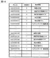
図19は、本発明の第2実施形態に係る分配部設定情報を説明する図である。 FIG. 19 is a diagram for explaining distribution unit setting information according to the second embodiment of the present invention.
本実施形態においては、分配部6−1、6−2が必要とする情報の一部について、配信部5から送信される分配部設定情報に基づいて、分配部6自身が内部の図示しないレジスターに設定できるようになっている。分配部設定情報は、設定する分配部6を特定する分配部IDに対して、画像データの色数と、搬送方向の画像サイズと、幅方向の画像サイズと、分配部6が取り込むべき画像データの色(取込対象色)と、分配部6が取り込むべき画像データのライン(取込対象ライン)と、ヘッドコントローラー接続状態とを対応付けた情報となっている。
In the present embodiment, for a part of information required by the distribution units 6-1 and 6-2, the
ここで、ヘッドコントローラー接続状態情報とは、対応する分配部6の分配ボード部11のスロット27に対するヘッドコントローラー7の接続状態(接続有無)を示す情報であり、例えば、各スロット27における接続状態を示すデータとしてそれぞれ1ビットずつ割り当て、対応するスロット27にヘッドコントローラー7が接続されている場合には、ビットを”1”とし、接続されていない場合には、ビットを”0”とするようにしている。このヘッドコントローラー接続状態を参照することにより、一部のスロット27に対してヘッドコントローラー7が接続されていない場合であっても、転送先アドレス生成部22Eが画像データを転送すべきヘッドコントローラー7の接続されているスロット27を特定し、対応する転送先アドレスを生成することができる。
Here, the head controller connection state information is information indicating the connection state (connection presence / absence) of the
次に、本発明の第3実施形態に係るプリンターについて説明する。 Next, a printer according to a third embodiment of the invention will be described.
本発明の第3実施形態に係るプリンターは、図15に示す第2実施形態に係るプリンターとは、使用しているヘッドの構成及び配置が異なるとともに、受信ボード部10のフィルタリング部22Hの機能が異なっているのみであり、その他の構成については同様である。
The printer according to the third embodiment of the present invention differs from the printer according to the second embodiment shown in FIG. 15 in the configuration and arrangement of the heads used, and the function of the
図20は、本発明の第3実施形態に係るヘッドの配置及び構成を説明する図である。図20Aは、ヘッドの配置を示すプリンター3の上面図であり、図20Bは、ヘッドの上面図である。なお、図20A、図20Bにおいては、各ノズルについては、上面から透視した様子を示している。
FIG. 20 is a diagram illustrating the arrangement and configuration of the head according to the third embodiment of the invention. FIG. 20A is a top view of the
本実施形態のプリンター3においては、複数のヘッド列9−1、9−2が配置されている。ヘッド列9−1は、シアン及びマゼンタの印刷を担当し、ヘッド列9−2は、イエロー及びブラックの印刷を担当するようになっている。
In the
本実施形態のヘッド15(15−1〜15−24)は、図20Bに示すように幅方向にノズル80C、80M、80Y,80Kが並んでいる4つのノズル列を有する。上流側の2つのノズル列と、下流側の2つのノズル列とは、それぞれ異なる1色のインクを吐出するためのノズル列である。すなわち、ヘッド15−1〜15−12については、上流側の2つのノズル列がシアンを吐出するためのノズル列であり、下流側の2つのノズル列がマゼンタを吐出するためのノズル列である。また、ヘッド15−13〜15−24については、上流側の2つのノズル列がイエローを吐出するためのノズル列であり、下流側の2つのノズル列がブラックを吐出するためのノズル列である。各色のインクを吐出するための2つのノズル列のノズルの幅方向Yの位置は、互いにノズルピッチの半分だけずれている。 The head 15 (15-1 to 15-24) of this embodiment has four nozzle rows in which nozzles 80C, 80M, 80Y, and 80K are arranged in the width direction as shown in FIG. 20B. The two upstream nozzle rows and the two downstream nozzle rows are nozzle rows for ejecting different colors of ink. That is, for the heads 15-1 to 15-12, the two upstream nozzle rows are nozzle rows for discharging cyan, and the two downstream nozzle rows are nozzle rows for discharging magenta. . Regarding the heads 15-13 to 15-24, the two upstream nozzle rows are nozzle rows for discharging yellow, and the two downstream nozzle rows are nozzle rows for discharging black. . The positions in the width direction Y of the nozzles of the two nozzle rows for ejecting ink of each color are shifted from each other by half the nozzle pitch.
本実施形態では、ヘッド列9−1におけるヘッド15−1〜15−12のノズル80C、80Mの幅方向における配置位置は、ヘッド列9−2のヘッド15−13〜15−24のノズル80Y、80Kの幅方向における配置位置と同じ位置となっている。
In the present embodiment, the positions of the
本実施形態では、受信ボード部10のハードウエア構成は第2実施形態の受信ボード部10と同様であり、第2実施形態とは、受信ボード部10における設定情報を異ならせることにより、フィルタリング部22Hが異なる機能を有するようになっている。
In this embodiment, the hardware configuration of the receiving
フィルタリング部22Hには、画像データ中の取込対象となるカラーが設定されている。フィルタリング部22Hは、当該設定に基づいて、画像データから必要なカラーの画像データのみを取り込んでいる。例えば、分配部6−1の受信ボード部10のフィルタリング部22Hには、シアンとマゼンタの画像データを取り込むように設定され、分配部6−2の受信ボード部10のフィルタリング部22Hには、イエローとブラックの画像データを取り込むように設定されている。なお、フィルタリング部22Hの設定については、図18に示す分配部設定情報中の取込対象色に基づいて設定することができる。
In the
以上、本発明を実施形態に基づいて説明したが、本発明は上述した実施の形態に限られず、他の様々な態様に適用可能である。 Although the present invention has been described based on the embodiments, the present invention is not limited to the above-described embodiments, and can be applied to various other modes.
例えば、上記実施形態では、ヘッド列は、最大印刷可能幅の全体を印刷可能にするために、最大印刷可能幅の一部のみを印刷可能なヘッドを複数備えるとともに、これらヘッドを最大印刷可能幅の全体の印刷を可能にするように配置していたが、本発明はこれに限られず、最大印刷可能幅の全体を印刷可能な1つのヘッド、すなわち、最大印刷可能幅の全体を印刷できるように複数のノズルが配置されている1つのヘッドを備えるようにしてもよい。また、上記実施形態では、複数のノズルが幅方向に並ぶようにしていたが、本発明はこれに限られず、複数のノズルが幅方向とは異なる、搬送方向と交差する方向に並ぶようにしてもよく、要は、幅方向の全体に亘ってノズルが配置されるようにすればよい。 For example, in the above-described embodiment, the head row includes a plurality of heads capable of printing only a part of the maximum printable width in order to enable printing of the entire maximum printable width, and these heads are provided with the maximum printable width. However, the present invention is not limited to this, and one head capable of printing the entire maximum printable width, that is, the entire maximum printable width can be printed. One head in which a plurality of nozzles are arranged may be provided. In the above embodiment, the plurality of nozzles are arranged in the width direction. However, the present invention is not limited to this, and the plurality of nozzles are arranged in a direction that is different from the width direction and intersects the conveyance direction. In short, the nozzle may be arranged over the entire width direction.
また、上記実施形態では、ヘッド全体の複数のノズル(ノズル群)を最小の単位として制御するヘッドコントローラーを備えるようにしていたが、本発明はこれに限られず、例えば、ヘッドの一部のノズル群を単位として制御するコントローラーを備えるようにし、分配ボード部は、1以上のコントローラーに対して対応する画像データを送信するようにしてもよい。 In the above embodiment, the head controller that controls the plurality of nozzles (nozzle group) of the entire head as a minimum unit is provided. However, the present invention is not limited to this. For example, some nozzles of the head A controller that controls a group as a unit may be provided, and the distribution board unit may transmit corresponding image data to one or more controllers.
また、上記実施形態では、画像データと、転送先アドレスと、次転送先アドレスとを組として、1クロックに合わせて別の信号線で送信するようにしていたが、これに限られず、画像データと、転送先アドレスと、次転送先アドレスとを組としたデータを同一の信号線により送信するようにしてもよい。 In the above-described embodiment, the image data, the transfer destination address, and the next transfer destination address are paired and transmitted through another signal line in synchronization with one clock. However, the present invention is not limited to this. In addition, data including a combination of the transfer destination address and the next transfer destination address may be transmitted through the same signal line.
また、上記実施形態では、受信ボード部10と複数の分配ボード部11−1〜11−3とは、カスケード接続していたが、これに限られず、例えば、受信ボード部10と、複数の分配ボード部11−1〜11−3とをバス型のネットワークで接続するようにしてもよく、要は、受信ボード部10から分配ボード部に対して直接又は、間接的にデータを送信できればよい。
In the above-described embodiment, the
また、上記実施形態では、転送先アドレスと、次転送先アドレスとを同時に送信するようにしていたが、これに限られず、少なくとも転送先への画像データの転送が終了する前に、次転送先アドレスを送信するようにすればよい。このようにすると、転送先への画像データの送信が完了した後に、次の転送先の状態の問い合わせを開始する場合に比して、迅速に判断結果が返ってくるので、迅速に次の転送先への画像データの送信を開始することができ、通信効率を向上することができる。 In the above embodiment, the transfer destination address and the next transfer destination address are transmitted at the same time. However, the present invention is not limited to this, and at least before the transfer of the image data to the transfer destination is completed, the next transfer destination is sent. The address may be transmitted. In this way, after the transmission of image data to the transfer destination is completed, the judgment result is returned more quickly than when an inquiry about the status of the next transfer destination is started. Transmission of image data to the destination can be started, and communication efficiency can be improved.
また、上記実施形態では、搬送方向に2列のヘッド列を備えるようにしていたが、本発明はこれに限られず、搬送方向に3列以上のヘッド列を備えるようにしてもよい。 In the above embodiment, two head rows are provided in the transport direction. However, the present invention is not limited to this, and three or more head rows may be provided in the transport direction.
また、上記実施形態では、画像形成装置としてラインインクジェットプリンターを例に説明していたが、本発明はこれに限られず、インク以外の液体を噴射させる画像形成装置や、トナー等の粉状体を飛翔させる画像形成装置にも適用できる。 In the above embodiment, a line inkjet printer has been described as an example of the image forming apparatus. However, the present invention is not limited to this, and an image forming apparatus that ejects a liquid other than ink or a powdery substance such as toner is used. The present invention can also be applied to an image forming apparatus that flies.
1 画像形成システム、2 PC、3 ラインインクジェットプリンター PC本体部、5 転送部、6 分配部、7(7−1〜7−12) ヘッドコントローラー、8(8−1〜8−24) ヘッド、9 ヘッド列、10 受信ボード部、11 分配ボード部、12 ベルト、21 コネクター、22 FPGA、22A 受信部、22B データ格納処理部、22C 読出アドレス生成部、22D データ読出処理部、22E 転送先アドレス生成部、22F データ転送部、22G Busy管理部、23 メモリー、24 スロット、25 コネクター、26 FPGA、26A 受信部、26B Busy判定部、26C 自身データ判定部、26D 転送先判定部、26E ヘッドコン転送部、27 スロット。
DESCRIPTION OF
Claims (4)
最上位となる第1の分配処理部から最下位となる第2の分配処理部まで、上位の分配処理部と下位の分配処理部とが通信可能に接続されるとともに、前記第1の分配処理部は、前記転送処理部と通信可能に接続されて構成され、
前記転送処理部は、
画像データを記憶するメモリーと、
転送先とするコントローラーを示す転送先識別情報を決定する転送先決定手段と、
前記転送先の前記コントローラーに送信する画像データを前記メモリーから読み出す画像データ読出手段と、
前記転送先識別情報と前記画像データとを前記第1の分配処理部に送信するデータ送信手段とを有し、
前記分配処理部は、
転送処理部又は上位の分配処理部から前記画像データと、前記転送先識別情報とを受信する受信手段と、
受信した前記転送先識別情報が示すコントローラーが、当該分配処理部自身が担当するコントローラーである場合に、受信した前記画像データを前記コントローラーに送信する配信手段と、
前記画像データと、前記転送先識別情報とを下位の分配処理部に送信する下位送信手段とを有する画像形成装置。 A plurality of controllers for controlling the nozzle group for forming an image on the image forming medium based on the image data and a part of the plurality of controllers for controlling the nozzle group in charge of the controller A plurality of distribution processing units for transmitting the image data to the controller, and a transfer processing unit for transferring the image data to the plurality of distribution processing units,
An upper distribution processing unit and a lower distribution processing unit are communicably connected to the first distribution processing unit from the first distribution processing unit that is the highest level to the second distribution processing unit that is the lowest level. The unit is configured to be communicably connected to the transfer processing unit,
The transfer processing unit
A memory for storing image data;
Transfer destination determining means for determining transfer destination identification information indicating a controller as a transfer destination;
Image data reading means for reading image data to be transmitted to the transfer destination controller from the memory;
Data transmission means for transmitting the transfer destination identification information and the image data to the first distribution processing unit;
The distribution processing unit includes:
Receiving means for receiving the image data and the transfer destination identification information from a transfer processing unit or a higher-level distribution processing unit;
When the controller indicated by the received transfer destination identification information is a controller in charge of the distribution processing unit itself, a distribution unit that transmits the received image data to the controller;
An image forming apparatus comprising: a lower transmission unit that transmits the image data and the transfer destination identification information to a lower distribution processing unit.
外部装置から前記分配処理部へのコントローラーの接続状態を示す状態情報を受信する状態情報受信手段を更に有し、
前記転送先決定手段は、前記状態情報に基づいて、前記画像データの前記転送先識別情報を決定する
請求項1に記載の画像形成装置。 The transfer processing unit
It further has status information receiving means for receiving status information indicating the connection status of the controller from the external device to the distribution processing unit,
The image forming apparatus according to claim 1, wherein the transfer destination determination unit determines the transfer destination identification information of the image data based on the state information.
請求項1又は請求項2に記載の画像形成装置。 The image forming apparatus according to claim 1, wherein the plurality of distribution processing units have the same hardware configuration.
請求項1乃至請求項3のいずれか一項に記載の画像形成装置。 The distribution processing unit has an upper connector for communicably connecting the transfer processing unit or the upper distribution processing unit and a lower connector for communicably connecting the lower distribution processing unit. 4. The image forming apparatus according to claim 1, wherein the upper connector and the lower connector are disposed at substantially symmetrical positions with respect to a board for configuring the distribution processing unit. 5. .
Priority Applications (1)
| Application Number | Priority Date | Filing Date | Title |
|---|---|---|---|
| JP2008322191A JP2010143052A (en) | 2008-12-18 | 2008-12-18 | Image forming apparatus |
Applications Claiming Priority (1)
| Application Number | Priority Date | Filing Date | Title |
|---|---|---|---|
| JP2008322191A JP2010143052A (en) | 2008-12-18 | 2008-12-18 | Image forming apparatus |
Publications (1)
| Publication Number | Publication Date |
|---|---|
| JP2010143052A true JP2010143052A (en) | 2010-07-01 |
Family
ID=42563985
Family Applications (1)
| Application Number | Title | Priority Date | Filing Date |
|---|---|---|---|
| JP2008322191A Pending JP2010143052A (en) | 2008-12-18 | 2008-12-18 | Image forming apparatus |
Country Status (1)
| Country | Link |
|---|---|
| JP (1) | JP2010143052A (en) |
-
2008
- 2008-12-18 JP JP2008322191A patent/JP2010143052A/en active Pending
Similar Documents
| Publication | Publication Date | Title |
|---|---|---|
| EP2072260B1 (en) | Head element substrate, recording head, and recording apparatus | |
| US7874630B2 (en) | Recording system having a plurality of controllers arranged respectively for a plurality of recording heads | |
| US8570575B2 (en) | Image forming apparatus, method of controlling the same, and image processing apparatus performing image formation on the basis of a plurality of pieces of image data for different colors | |
| JP5470834B2 (en) | Image forming apparatus | |
| US10434768B2 (en) | Printing system comprising a microelectromechanical die and an application specific integrated circuit | |
| JP5446248B2 (en) | Image forming apparatus, image forming system, and head device | |
| US9630402B2 (en) | Ink jet head and printing apparatus | |
| JP5233649B2 (en) | Image forming apparatus | |
| JP2010143052A (en) | Image forming apparatus | |
| JP5202394B2 (en) | Droplet discharge head and droplet discharge apparatus | |
| US8491077B2 (en) | Printing device and printing method | |
| JP2010240937A (en) | Image formation device, image forming system, and image forming method | |
| US20130070270A1 (en) | Printing device and control method of printing device | |
| JP2022141103A (en) | recording device | |
| JP6938978B2 (en) | Image forming device, ink ejection method, liquid ejection device | |
| JP2010149340A (en) | Image forming apparatus | |
| JP6877244B2 (en) | Recording device and its control method | |
| JP2010120331A (en) | Image forming apparatus | |
| JP2023011385A (en) | Head system, liquid discharge device and liquid discharge method | |
| JP2010076147A (en) | Liquid droplet ejection control apparatus and liquid droplet ejecting apparatus | |
| JP4865534B2 (en) | Substrate for liquid discharge head and liquid discharge head | |
| JP2010194837A (en) | Image forming apparatus | |
| JP2012181585A (en) | Device system and chip | |
| JP2009149027A (en) | Image forming apparatus and image forming program | |
| JP2006259990A (en) | Printer controller |