JP2010143049A - Liquid jetting head and liquid jetting device - Google Patents

Liquid jetting head and liquid jetting device Download PDF

Info

Publication number
JP2010143049A
JP2010143049A JP2008322134A JP2008322134A JP2010143049A JP 2010143049 A JP2010143049 A JP 2010143049A JP 2008322134 A JP2008322134 A JP 2008322134A JP 2008322134 A JP2008322134 A JP 2008322134A JP 2010143049 A JP2010143049 A JP 2010143049A
Authority
JP
Japan
Prior art keywords
liquid
nozzle
flow path
droplet discharge
droplet
Prior art date
Legal status (The legal status is an assumption and is not a legal conclusion. Google has not performed a legal analysis and makes no representation as to the accuracy of the status listed.)
Withdrawn
Application number
JP2008322134A
Other languages
Japanese (ja)
Inventor
Torahiko Kanda
虎彦 神田
Current Assignee (The listed assignees may be inaccurate. Google has not performed a legal analysis and makes no representation or warranty as to the accuracy of the list.)
Fujifilm Business Innovation Corp
Original Assignee
Fuji Xerox Co Ltd
Priority date (The priority date is an assumption and is not a legal conclusion. Google has not performed a legal analysis and makes no representation as to the accuracy of the date listed.)
Filing date
Publication date
Application filed by Fuji Xerox Co Ltd filed Critical Fuji Xerox Co Ltd
Priority to JP2008322134A priority Critical patent/JP2010143049A/en
Publication of JP2010143049A publication Critical patent/JP2010143049A/en
Withdrawn legal-status Critical Current

Links

Images

Landscapes

  • Particle Formation And Scattering Control In Inkjet Printers (AREA)

Abstract

<P>PROBLEM TO BE SOLVED: To provide a liquid jetting head and liquid droplet jetting device that highly efficiently and stably jet a highly viscous liquid mixture. <P>SOLUTION: Each channel member 12 is bendable in a liquid droplet jetting direction and its reverse direction, and jets a liquid that has reached a nozzle 16 through a channel 13, as a liquid droplet 2 in the jetting direction by virtue inertia. Until reaching the nozzle 16, liquids A and B are fed within the channel 13 from both the ends in longitudinal direction as shown in Fig.5(B). In a section M which is a reaction progress area shown by an ellipse in Fig.5(C), the liquids A and B brought into contact with each other near the nozzle 16 are mixed, and consequently their reaction progresses and the mixture becomes highly viscous. Then, as shown in Fig.5(D), a liquid droplet 2 is jetted from the nozzle 16. <P>COPYRIGHT: (C)2010,JPO&INPIT

Description

本発明は液滴吐出ヘッドおよび液滴吐出装置に関し、特に高粘度の液を液滴として吐出する液滴吐出ヘッドおよび液滴吐出装置に関する。 The present invention relates to a droplet discharge head and a droplet discharge device, and more particularly to a droplet discharge head and a droplet discharge device that discharge high-viscosity liquid as droplets.

液滴吐出装置として知られている現在市販されている水性インクジェットプリンターは、概ね粘度5cps前後、高々10cpsオーダの染料液や顔料インクを採用している。媒体に着弾した際の液滲み防止や、光学的な色濃度アップ、含水量低減による媒体の膨潤抑制/短時間乾燥、あるいは、そうした高品質液をトータル設計するに当たり自由度が大きくとれる等の理由から、インク粘度を増加することによってプリント性能は向上できることが知られている。   A currently marketed aqueous inkjet printer known as a droplet discharge device employs a dye solution or pigment ink having a viscosity of about 5 cps or so and an order of 10 cps at most. Reasons such as prevention of liquid bleeding when landing on the medium, increase in optical color density, suppression of swelling / short time drying of the medium due to reduced water content, or greater freedom in total design of such high quality liquid Therefore, it is known that the printing performance can be improved by increasing the ink viscosity.

本願発明者らは、梁に圧縮と回転運動を与え、座屈曲げ方向が反転する際の急峻な上下運動を利用して、ノズルから高粘度液滴を所望の方向に慣性離脱させる液滴吐出ヘッドを先に出願した(特許文献1〜4参照)。   The inventors of the present application have applied a compressive and rotational motion to the beam, and a droplet discharge that causes a high-viscosity droplet to inertially release from the nozzle in a desired direction using the steep vertical motion when the seat bending direction is reversed. The head was filed earlier (see Patent Documents 1 to 4).

ところで、主に吐出液滴(インク)の色濃度制御を目的として、異なる2液を混合し吐出する技術が従来から知られている(特許文献5〜6参照)。
特願2004−322341号公報 特願2004−322342号公報 特願2004−322343号公報 特願2004−322344号公報 特開平6−071901号公報 特開平6−122201号公報
By the way, techniques for mixing and discharging two different liquids have been conventionally known mainly for the purpose of controlling the color density of discharged droplets (ink) (see Patent Documents 5 to 6).
Japanese Patent Application No. 2004-322341 Japanese Patent Application No. 2004-322342 Japanese Patent Application No. 2004-322343 Japanese Patent Application No. 2004-322344 JP-A-6-071901 JP-A-6-122201

本発明は、高粘度な混合液を高効率かつ安定に吐出できる液滴吐出ヘッドおよび液滴吐出装置を提供することを目的とする。   It is an object of the present invention to provide a droplet discharge head and a droplet discharge device that can discharge a highly viscous mixed liquid with high efficiency and stability.

請求項1に記載の液滴吐出ヘッドは、液滴を吐出するノズルと、混合により粘度が増加する少なくとも2種類の液体が前記ノズルに向けて別々に供給される液体流路部材と、前記液体流路部材と接合もしくは液体流路部材を含み、液滴吐出面に凹となるように座屈反転変形した後、液滴吐出方向に凸となるよう座屈反転変形し、前記ノズル近傍の液体に吐出方向の慣性を与えることにより、前記ノズルの近傍で混合された混合液の液滴を前記ノズルより吐出させる梁部材と、を備えたことを特徴とする。   The droplet discharge head according to claim 1 includes a nozzle that discharges droplets, a liquid flow path member that supplies at least two kinds of liquids whose viscosity increases by mixing to the nozzles separately, and the liquid The liquid in the vicinity of the nozzle includes a liquid flow path member joined to the flow path member, buckled and reversed so as to be concave on the droplet discharge surface, and then buckled and reversed so as to be convex in the droplet discharge direction. And a beam member for discharging droplets of the mixed liquid mixed in the vicinity of the nozzle from the nozzle by giving inertia in the discharge direction.

請求項2に記載の液滴吐出ヘッドは、請求項1に記載の構成において、前記液体流路部材の両端部からそれぞれ種類の異なる液体が前記ノズルに向けて供給されることを特徴とする。   According to a second aspect of the present invention, the liquid droplet ejection head according to the first aspect is characterized in that different types of liquid are supplied toward the nozzles from both ends of the liquid flow path member.

請求項3に記載の液滴吐出ヘッドは、請求項1または請求項2に記載の構成において、前記液体流路部材の流路は、長手方向に沿って仕切部材で仕切られていることを特徴とする。   According to a third aspect of the present invention, in the configuration of the first or second aspect, the flow path of the liquid flow path member is partitioned by a partition member along the longitudinal direction. And

請求項4に記載の液滴吐出ヘッドは、請求項1〜請求項3の何れか1項に記載の構成において、前記梁部材あるいは前記梁部材および前記液体流路部材は、前記ノズルより溢れた液体を液滴吐出方向の反対側に排出する液体排出部を備えたことを特徴とする。   The droplet discharge head according to claim 4 is the configuration according to any one of claims 1 to 3, wherein the beam member or the beam member and the liquid flow path member overflow from the nozzle. A liquid discharge unit that discharges the liquid to the side opposite to the droplet discharge direction is provided.

請求項5に記載の液滴吐出ヘッドは、請求項1〜請求項4の何れか1項に記載の構成において、吸引口が前記ノズルの近傍に向いた吸引路と、前記吸引路に負圧を発生させる負圧発生手段と、を備えたことを特徴とする。   According to a fifth aspect of the present invention, in the liquid droplet ejection head according to the first aspect, the suction path in which the suction port faces the vicinity of the nozzle and the negative pressure in the suction path in the configuration according to any one of the first to fourth aspects. And negative pressure generating means for generating.

請求項6に記載の液滴吐出ヘッドは、請求項5に記載の構成において、前記吸引路の前記吸引口へ空気を送る送風路と、前記送風路に正圧を発生させる送風手段と、を備えたことを特徴とする。   According to a sixth aspect of the present invention, in the configuration of the fifth aspect, the liquid droplet ejection head includes: a blower path that sends air to the suction port of the suction path; and a blower unit that generates a positive pressure in the blower path. It is characterized by having.

請求項7に記載の液滴吐出装置は、請求項1〜請求項6の何れか1項に記載の液滴吐出ヘッドを備えたことを特徴とする。   According to a seventh aspect of the present invention, there is provided a liquid droplet ejection apparatus including the liquid droplet ejection head according to any one of the first to sixth aspects.

請求項1に記載の液滴吐出ヘッドの構成によれば、本構成を有していない場合と比較して、混合により粘度が増加した混合液を高効率かつ安定に吐出できる液滴吐出ヘッドとすることができる。   According to the configuration of the droplet discharge head according to claim 1, the droplet discharge head capable of discharging the mixed liquid whose viscosity has been increased by mixing with high efficiency and stability compared to the case where the present configuration is not provided. can do.

請求項2に記載の液滴吐出ヘッドの構成によれば、本構成を有していない場合と比較して、ノズル位置を中心とする梁部材の構造対称性を高くし、梁部材の座屈動作を高精度化することができる。   According to the configuration of the droplet discharge head according to claim 2, compared to the case without the present configuration, the structural symmetry of the beam member around the nozzle position is increased, and the beam member is buckled. The operation can be made highly accurate.

請求項3に記載の液滴吐出ヘッドの構成によれば、本構成を有していない場合と比較して、2液の混合点がノズル箇所より外れることなく、かつ流路端部を加工して簡易にノズル形成を可能とすることができる。   According to the configuration of the droplet discharge head of the third aspect, compared with the case where the present configuration is not provided, the mixing point of the two liquids is not deviated from the nozzle portion, and the end of the flow path is processed. Thus, it is possible to easily form a nozzle.

請求項4に記載の液滴吐出ヘッドの構成によれば、本構成を有していない場合と比較して、ノズル近傍での液停滞を抑制できる。   According to the configuration of the droplet discharge head of the fourth aspect, liquid stagnation in the vicinity of the nozzle can be suppressed as compared with the case where the configuration is not provided.

請求項5に記載の液滴吐出ヘッドの構成によれば、本構成を有していない場合と比較して、ノズル近傍を清浄に保つことができる。   According to the configuration of the droplet discharge head of the fifth aspect, the vicinity of the nozzle can be kept clean as compared with the case where the configuration is not provided.

請求項6に記載の液滴吐出ヘッドの構成によれば、本構成を有していない場合と比較して、吸引口からノズル近傍のゴミや残留液の吸引を容易にすることができる。   According to the configuration of the droplet discharge head of the sixth aspect, it is possible to facilitate the suction of dust and residual liquid in the vicinity of the nozzle from the suction port as compared with the case where the present configuration is not provided.

請求項7に記載の液滴吐出装置の構成によれば、本構成を有していない場合と比較して、座屈反転変形を採用しない場合と比べ、混合により粘度が増加した混合を、高効率かつ安定に吐出できる液滴吐出装置とすることができる。   According to the configuration of the droplet discharge device according to the seventh aspect, compared to the case where the present configuration is not provided, compared to the case where the buckling reversal deformation is not adopted, the mixing whose viscosity is increased by mixing is increased. It can be set as the droplet discharge apparatus which can discharge efficiently and stably.

<基本構成>
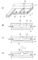
図1には、本発明の実施形態に係る液滴吐出ヘッドの基本構造が示されている。
<Basic configuration>
FIG. 1 shows a basic structure of a droplet discharge head according to an embodiment of the present invention.

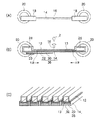
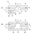
図1(A)、(B)に示すように液滴吐出ヘッド10は、内部に液流路13を備え長さ方向略中央にノズル16を備えた中空チューブ状の流路部材12と、流路部材12を支持する梁部材14とが柱状に接合され、両端を支持部材18が支持する構造となっている。   As shown in FIGS. 1 (A) and 1 (B), the droplet discharge head 10 includes a hollow tube-shaped flow path member 12 having a liquid flow path 13 therein and a nozzle 16 at a substantially central portion in the length direction, and a flow path. The beam member 14 that supports the road member 12 is joined in a columnar shape, and the support member 18 supports both ends.

梁部材14にはピエゾ素子30が接合され、さらにピエゾ素子30には信号電極32が接合され梁部材14、ピエゾ素子30、信号電極32でアクチュエータ36を構成している。梁部材14はピエゾ素子30の共通電極を兼ねており、梁部材14と信号電極32とでピエゾ素子30を挟む構造となっている。信号電極32の一方の端には電極パッド33が設けられ、配線34にて図示しないスイッチングICと接続されている。このスイッチングICからの信号によりピエゾ素子30は駆動され、梁部材14を撓ませるか撓ませないかの制御が行われる。   A piezo element 30 is joined to the beam member 14, and a signal electrode 32 is joined to the piezo element 30, and the beam member 14, the piezo element 30, and the signal electrode 32 constitute an actuator 36. The beam member 14 also serves as a common electrode of the piezo element 30, and has a structure in which the piezo element 30 is sandwiched between the beam member 14 and the signal electrode 32. An electrode pad 33 is provided at one end of the signal electrode 32, and is connected to a switching IC (not shown) by a wiring 34. The piezo element 30 is driven by a signal from the switching IC, and the beam member 14 is controlled to be bent or not bent.

流路部材12は、液滴吐出方向(図中上)および逆方向に撓み可能であり、液溜まり24から供給され液流路13を通ってノズル16まで達した液を、慣性によって吐出方向に液滴として吐出する。   The flow path member 12 can bend in the liquid droplet ejection direction (upper direction in the drawing) and in the opposite direction, and the liquid supplied from the liquid reservoir 24 and reaches the nozzle 16 through the liquid flow path 13 in the ejection direction by inertia. Discharge as droplets.

このとき、回転エンコーダ20に設けられた2箇所の液溜まり24からはそれぞれ別個の液体、すなわちA液とB液とが液流路13に供給され、長手方向両端よりノズル16近傍にて合流、混合され、ノズル16より液滴2として吐出される。   At this time, separate liquids, that is, A liquid and B liquid, are supplied to the liquid flow path 13 from the two liquid reservoirs 24 provided in the rotary encoder 20, and merge in the vicinity of the nozzle 16 from both ends in the longitudinal direction. It is mixed and discharged as a droplet 2 from the nozzle 16.

支持部材18は回転エンコーダ20の回転中心からオフセットされた位置にて両側から押圧され、あるいは曲げ方向に力が加えられインク液吐出方向あるいは逆方向に梁部材14と接合した流路部材12を撓ませる。支持部材18は、例えば図1(A)の紙面前後方向に長い棒状でもよく、支持部材18に複数の流路部材12が設けられた梯子状の構造であってもよい。   The support member 18 is pressed from both sides at a position offset from the rotation center of the rotary encoder 20, or a force is applied in the bending direction to bend the flow path member 12 joined to the beam member 14 in the ink discharge direction or in the opposite direction. I will. The support member 18 may have, for example, a rod shape that is long in the front-rear direction of FIG. 1A, or may have a ladder-like structure in which a plurality of flow path members 12 are provided on the support member 18.

図1(C)は、梁部材14の斜視図である。図1(C)に示すように流路部材12は中空チューブ状の部材を複数並べ、長さ方向の略同一位置にノズル16を切り欠いて設けた構造とされている。   FIG. 1C is a perspective view of the beam member 14. As shown in FIG. 1C, the flow path member 12 has a structure in which a plurality of hollow tube-like members are arranged and the nozzles 16 are cut out at substantially the same position in the length direction.

ここで用いられる液は前述のように、主に吐出液滴(インク)の色濃度制御を目的として、異なる2液を混合し吐出するものであり、また混合に伴い粘度が高くなるような液体である。   As described above, the liquid used here is a liquid in which two different liquids are mixed and discharged mainly for the purpose of controlling the color density of the discharged droplets (ink), and the liquid whose viscosity increases with mixing. It is.

<座屈反転吐出>
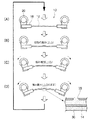
図2および図3には本発明に係る液滴吐出ヘッドの梁部材あるいは流路部材の撓み方向と座屈反転の関係が示されている。両図とも、支持部材に複数の流路部材が梯子状に設けられた構造の液滴吐出ヘッドにおいて、その中の1本の流路部材に注目して変形の様子を表したものである。
<Buckling reversal discharge>
2 and 3 show the relationship between the bending direction of the beam member or flow path member of the droplet discharge head according to the present invention and the buckling reversal. In both figures, in a droplet discharge head having a structure in which a plurality of flow path members are provided on a support member in a ladder shape, the state of deformation is shown paying attention to one of the flow path members.

液滴2を吐出しないように制御された場合、まず図2(A)のように回転エンコーダ20が逆回転(流路部材12を引き伸ばす方向へ回転)し、初期状態では吐出方向へ凸形状となっている流路部材12を真っ直ぐに伸ばす。   When control is performed so as not to eject the droplet 2, first, the rotary encoder 20 rotates in the reverse direction (rotates in the direction in which the flow path member 12 is stretched) as shown in FIG. The formed flow path member 12 is straightened.

次いで図2(B)のように、流路部材12の伸びを緩めると、流路部材12に吐出を指示する信号が送られないためアクチュエータ36が駆動されず、吐出方向に凸となるように撓んだ状態のままとなる。   Next, as shown in FIG. 2B, when the extension of the flow path member 12 is loosened, the actuator 36 is not driven because the signal instructing the discharge is not sent to the flow path member 12, so that it becomes convex in the discharge direction. It remains in a bent state.

さらに図2(C)および図2(D)で回転エンコーダ20を吐出方向に正回転させ続けると、吐出方向に凸となるように撓んだ状態のまま撓み量が増大してゆくが、座屈反転による流路部材12の吐出方向への変形が起こらないため、ノズル16より液滴2の吐出には至らない。   2C and 2D, if the rotary encoder 20 is continuously rotated in the forward direction in the discharge direction, the amount of flexure increases while remaining bent in the direction of discharge. Since the deformation in the discharge direction of the flow path member 12 due to bending inversion does not occur, the liquid droplet 2 is not discharged from the nozzle 16.

これに対して液滴2を吐出するように液滴吐出ヘッド10が制御された場合、まず図3(A)のように回転エンコーダ20が反転(流路部材12を引き伸ばす方向へ回転)し、初期状態では吐出方向へ凸形状となっている流路部材12を真っ直ぐに伸ばし、撓みのない状態とする。   On the other hand, when the droplet discharge head 10 is controlled so as to discharge the droplet 2, first, the rotary encoder 20 is reversed (rotated in the direction of extending the flow path member 12) as shown in FIG. In the initial state, the flow path member 12 having a convex shape in the discharge direction is straightly extended so as not to bend.

次いで図3(B)のように流路部材12に吐出を指示する信号が図示しないスイッチングICより送られてアクチュエータ36が駆動され、吐出方向に凹となるように撓んだ状態となる。   Next, as shown in FIG. 3B, a signal for instructing ejection to the flow path member 12 is sent from a switching IC (not shown), and the actuator 36 is driven to bend so as to be concave in the ejection direction.

さらに図3(C)で回転エンコーダ20を図中矢印方向に正回転させると、流路部材12は回転エンコーダ20に近い方、すなわち長手方向両端側から次第に吐出方向(図中上)に凸へと撓み方向が変化する。   Further, when the rotary encoder 20 is rotated forward in the direction of the arrow in FIG. 3C, the flow path member 12 gradually protrudes toward the discharge direction (upward in the figure) from the side closer to the rotary encoder 20, that is, from both ends in the longitudinal direction. The bending direction changes.

この変化が両端から中央に近付くと、流路部材12(あるいは梁部材14)はある点で急峻な座屈反転を起こし、図3(D)に示すように液滴吐出方向(図中上)へと急激に変形する。   When this change approaches the center from both ends, the flow path member 12 (or the beam member 14) undergoes a steep buckling reversal at a certain point, and as shown in FIG. Deforms rapidly.

流路部材12の長さ方向略中央にはノズル16が設けられているため、流路部材12内部を給送されノズル16まで達している液はこの座屈反転による流路部材12の吐出方向への変形に伴い、ノズル16から液滴2として吐出される。   Since the nozzle 16 is provided substantially at the center in the length direction of the flow path member 12, the liquid fed through the flow path member 12 and reaching the nozzle 16 is discharged from the flow path member 12 by this buckling inversion. Along with the deformation, the liquid is ejected as a droplet 2 from the nozzle 16.

さらに図3(D)で撓み量が最大となり回転エンコーダ20が停止したのち、逆回転して流路部材12を平坦にする(図3(A))ことで流路部材12は初期位置図3(A)へ復帰する。   Further, in FIG. 3D, after the amount of bending becomes maximum and the rotary encoder 20 stops, the flow path member 12 is flattened by rotating backward (FIG. 3A) so that the flow path member 12 is in the initial position. Return to (A).

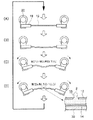
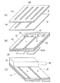
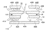
図4には本実施形態に係る液滴吐出ヘッドの、他の構造が示されている。すなわち、梁部材14の長手方向一端を回転エンコーダ20に保持された支持部材18に固定され、長手方向他端は固定端として、固定された支持部材18Bに保持されている。   FIG. 4 shows another structure of the droplet discharge head according to the present embodiment. That is, one end in the longitudinal direction of the beam member 14 is fixed to the support member 18 held by the rotary encoder 20, and the other end in the longitudinal direction is held as a fixed end by the fixed support member 18B.

また梁部材14に設けられた流路部材12には長手方向両端より液流路13が設けられており、長手方向一端よりA液が、長手方向他端よりB液が、それぞれ長手方向中央近傍に設けられたノズル16に向けて給送され、ノズル16近傍で混合される。   Further, the flow path member 12 provided in the beam member 14 is provided with a liquid flow path 13 from both ends in the longitudinal direction, and the liquid A from one end in the longitudinal direction and the liquid B from the other longitudinal end are respectively near the center in the longitudinal direction. Is fed toward the nozzle 16 provided in the nozzle 16 and mixed in the vicinity of the nozzle 16.

図4(A)に示すように梁部材14の回転エンコーダ20側半分を吐出側に凹、他端側半分を吐出側に凸とした初期状態より、図4(B)に示すように梁部材14(流路部材12)の両端よりA液、B液が液流路13内を給送され、ノズル16近傍で混合される。   From the initial state in which the half of the beam member 14 on the rotary encoder 20 side is concave on the discharge side and the other half of the beam member 14 is convex on the discharge side as shown in FIG. Liquid A and liquid B are fed from both ends of 14 (flow path member 12) through the liquid flow path 13 and mixed in the vicinity of the nozzle 16.

さらに図4(C)に示すように回転エンコーダ20が吐出方向に回転すると支持部材18によって保持されている梁部材14の一端より、吐出方向に凸となるように変形し始め、図4(D)に示すようにノズル16近傍(長手方向中央付近)が吐出方向に座屈反転し、ノズル16よりA液とB液が混合された液滴2が吐出される。   Further, as shown in FIG. 4C, when the rotary encoder 20 rotates in the discharge direction, it starts to deform so as to be convex in the discharge direction from one end of the beam member 14 held by the support member 18, and FIG. ), The vicinity of the nozzle 16 (near the center in the longitudinal direction) is buckled and reversed in the discharge direction, and the droplet 2 in which the liquid A and the liquid B are mixed is discharged from the nozzle 16.

<液混合と吐出>
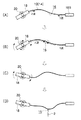
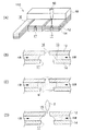
図5には本発明の第1実施形態に係る液滴吐出ヘッドのノズル近傍における液の混合と液滴の吐出が示されている。
<Liquid mixing and discharge>
FIG. 5 shows mixing of liquids and discharge of liquid droplets in the vicinity of the nozzles of the liquid droplet discharge head according to the first embodiment of the present invention.

図5(A)には液滴吐出ヘッド10のノズル16近傍の断面図が示されている。支持部材18に一端を保持された梁部材14上には流路部材12が設けられ、流路部材12の内部には長手方向に液流路13が設けられている。   FIG. 5A shows a cross-sectional view of the vicinity of the nozzle 16 of the droplet discharge head 10. A flow path member 12 is provided on the beam member 14 whose one end is held by the support member 18, and a liquid flow path 13 is provided in the longitudinal direction inside the flow path member 12.

例えばYAGレーザ50などによる貫通加工で形成されたノズル16に至るまで、図5(B)に示すように長手方向両端より液流路13の内部をそれぞれA液、B液が給送される。図5(C)に楕円で示される反応進行領域である区間Mでは、ノズル16近傍で接触したA液とB液とが混合され、反応が進行し高粘度化が起こる。   For example, the liquid A and the liquid B are fed through the inside of the liquid flow path 13 from both ends in the longitudinal direction as shown in FIG. 5B until reaching the nozzle 16 formed by the penetration processing using the YAG laser 50 or the like. In the section M, which is a reaction progress region indicated by an ellipse in FIG. 5C, the liquid A and the liquid B in contact with each other in the vicinity of the nozzle 16 are mixed, and the reaction proceeds to increase the viscosity.

次いで図5(D)に示されるようにノズル16より液滴2が吐出される。この液滴2は反応したA液、B液の混合液の大部分であり、高粘度化が進行し粘性が高い状態となっているが、梁部材14の座屈反転による慣性離脱で吐出されるため、高粘度の液滴2であっても吐出可能であり、剛体で形成された圧力室、絞り等を必要としない。   Next, as shown in FIG. 5D, the droplet 2 is discharged from the nozzle 16. These droplets 2 are the majority of the liquid mixture of the liquid A and the liquid B that have reacted, and the viscosity has been increased and the viscosity has been increased. However, the liquid droplets 2 are discharged by inertial separation due to the buckling reversal of the beam member 14. Therefore, even the highly viscous droplet 2 can be discharged, and a pressure chamber, a throttle, etc. formed of a rigid body are not required.

ここで、上記のA液およびB液について具体的に説明する。本発明ではAB2液として公知のDCLS(Double-Component Liquid System)技術を使用する。   Here, the A liquid and the B liquid will be specifically described. In the present invention, a well-known DCLS (Double-Component Liquid System) technique is used as the AB2 liquid.

従来から、2液を別々のヘッドで吐出し、媒体上で着弾した液体を混合することにより、色材の凝集を起こし、印字性能を向上する技術が知られている。媒体表面で色材を凝集させることで、媒体の内部に色材が浸透することを抑制でき、溶媒等は媒体の内部に浸透する。光学濃度の向上や滲みの防止を実現することを目的としている。   2. Description of the Related Art Conventionally, a technique is known in which two liquids are ejected by separate heads, and liquids that have landed on a medium are mixed to cause agglomeration of coloring materials and improve printing performance. By aggregating the color material on the surface of the medium, it is possible to suppress the color material from penetrating into the medium, and the solvent or the like penetrates into the medium. The objective is to improve optical density and prevent bleeding.

本発明では、上記のような液(インク)として、既に知られている酸−塩基(イオン)反応の2液(共に4cps程度)を混合吐出した。2液の一方(A液)として、例えばカルボン酸を有する高分子分散材を使った黒顔料インクを、また、他方(B液)には、例えば多価金属塩を含有する水溶液を用いた。   In the present invention, as the liquid (ink) as described above, two liquids (both of about 4 cps) of the already known acid-base (ion) reaction are mixed and discharged. As one of the two liquids (liquid A), for example, a black pigment ink using a polymer dispersion material having carboxylic acid was used, and as the other liquid (liquid B), an aqueous solution containing, for example, a polyvalent metal salt was used.

この場合、主溶媒は水であり、他に界面活性剤、粘度調整や保湿のためグリセリンを添加したものであり、混合前の2液のそれぞれの粘度は約50mPa・sに調整した。なお、粘度範囲は2〜200mPa・s、さらに好適には10〜100mPa・sが望ましい。すなわち2液の粘度が高過ぎると、2液がノズル16近傍の液流路13内部でぶつかった界面で混合(相互拡散)が起こりにくく、均一な反応をコントロールし難く、加えて着弾時のレベリングが進まずに液滴2が媒体表面で盛り上がった印字状態になってしまう。一方、A液およびB液が低粘度過ぎると、ノズル16近傍で急激に混合が進むため、やはり混合反応の制御が困難になる。   In this case, the main solvent was water, in addition to surfactant, glycerin added for viscosity adjustment and moisturization, and the viscosity of each of the two liquids before mixing was adjusted to about 50 mPa · s. The viscosity range is preferably 2 to 200 mPa · s, more preferably 10 to 100 mPa · s. That is, if the viscosity of the two liquids is too high, mixing (mutual diffusion) hardly occurs at the interface where the two liquids collide in the liquid flow path 13 in the vicinity of the nozzle 16, and it is difficult to control a uniform reaction. However, the liquid droplet 2 rises on the surface of the medium without progressing. On the other hand, if the liquid A and the liquid B are too low in viscosity, mixing rapidly proceeds in the vicinity of the nozzle 16, so that it is difficult to control the mixing reaction.

A液、B液の2液がノズル16近傍で混合された後は、色材の凝集、それに伴う液体の高粘度化が進行する。本願発明者らの検討によると、凝集の進行具合からミリ秒オーダで高粘度化が始まり、最終的には数千mPa・s以上に高粘度化する。液滴2として吐出の段階では概ね、数十〜数百mPa・sに高粘度化していると考えられる。   After the two liquids of liquid A and liquid B are mixed in the vicinity of the nozzle 16, aggregation of the coloring material and accompanying increase in the viscosity of the liquid proceed. According to the study by the inventors of the present application, the increase in viscosity starts on the order of milliseconds from the progress of aggregation, and finally the viscosity increases to several thousand mPa · s or more. It is considered that the viscosity of the droplet 2 is generally increased to several tens to several hundreds mPa · s at the stage of ejection.

なお、混合2液の組合せは、上述のようにイオン反応で高粘度化するものに限定されない。例えば、混合によってポリマー化するような液体の組合せにおいても、同様の効果を得ることができる。   In addition, the combination of 2 liquid mixture is not limited to what raises viscosity by an ionic reaction as mentioned above. For example, the same effect can be obtained in a combination of liquids that are polymerized by mixing.

<製造工程>
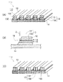
図6には、本発明の第1実施形態に係る液滴吐出ヘッドの製造工程が示されている。先ず厚さ20μm程度のSUS板をスリット幅70μm程度で一列飛ばしにエッチング処理(スリットエッチ)し、梁部材14とする。
<Manufacturing process>
FIG. 6 shows a manufacturing process of the droplet discharge head according to the first embodiment of the present invention. First, an SUS plate having a thickness of about 20 μm is subjected to etching processing (slit etching) in a row with a slit width of about 70 μm to form a beam member 14.

図6(A)に示すように、吐出面裏側にPI(ポリイミド)フィルム12Bを融着した厚さ10μm程度のSUS板を流路部材12Bとしてスリット幅70μmでスリットエッチ処理する。   As shown in FIG. 6A, slit etching is performed with a slit width of 70 μm using a SUS plate having a thickness of about 10 μm with a PI (polyimide) film 12B fused to the back side of the discharge surface as a flow path member 12B.

次いで図6(C)に示されるように、流路部材12Bの吐出面側にPIフィルム12Cを熱融着する。YAGレーザ50などでノズル16を穿孔し、支持部材18の長手方向に並列に設けられた梁部材14を互いに分離する。また同時に流路部材12Bに設けられたスリット(=液流路13)と連通する液溜まり24がPIフィルム12Cを除去することで設けられる。このとき梁部材14、流路部材12Bは予めスリットエッチ処理が行われているので、表面のPIフィルム12Cのみレーザアブレーションで除去する。   Next, as shown in FIG. 6C, the PI film 12C is heat-sealed to the discharge surface side of the flow path member 12B. The nozzle 16 is perforated with a YAG laser 50 or the like, and the beam members 14 provided in parallel in the longitudinal direction of the support member 18 are separated from each other. At the same time, a liquid reservoir 24 communicating with a slit (= liquid flow path 13) provided in the flow path member 12B is provided by removing the PI film 12C. At this time, since the beam member 14 and the flow path member 12B have been slit-etched in advance, only the surface PI film 12C is removed by laser ablation.

さらに吐出裏面からは長手方向半分までの領域に、予め信号電極32が形成されたピエゾ素子30が接合される。支持部材18内に設けられた液溜まり24に、図示しない送液ポンプより液を供給される供給ポート25が接続され、液滴吐出ヘッド10として形成される。   Furthermore, the piezoelectric element 30 on which the signal electrode 32 is formed in advance is joined to a region from the discharge back surface to the half in the longitudinal direction. A supply port 25 to which a liquid is supplied from a liquid feed pump (not shown) is connected to a liquid reservoir 24 provided in the support member 18, and is formed as a droplet discharge head 10.

<背面開放>
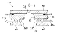
図7には、本発明の第2実施形態に係る液滴吐出ヘッド110のノズル16近傍の断面図が示されている。液滴吐出ヘッド110は支持部材18に一端を保持された梁部材14上に流路部材12が設けられ、流路部材12の内部には長手方向に液流路13が設けられている。
<Rear opening>
FIG. 7 shows a cross-sectional view of the vicinity of the nozzle 16 of the droplet discharge head 110 according to the second embodiment of the present invention. In the droplet discharge head 110, a flow path member 12 is provided on a beam member 14 held at one end by a support member 18, and a liquid flow path 13 is provided in the longitudinal direction inside the flow path member 12.

図7(A)に示すように液滴吐出ヘッド110の流路部材12は、内部長手方向に貫通した液流路13と、長さ方向略中央に設けられたノズル16とを備え、ノズル16の裏側(反吐出方向側)にはノズル16から梁部材14まで吐出方向に貫通した開口17が設けられている。開口17は、例えばYAGレーザ50などによる貫通加工で形成され、例えば表面(吐出側面)に50μmのノズル16が、裏面(反吐出面側)に75μmの開口17が形成されている。   As shown in FIG. 7A, the flow path member 12 of the droplet discharge head 110 includes a liquid flow path 13 penetrating in the internal longitudinal direction, and a nozzle 16 provided substantially at the center in the length direction. An opening 17 penetrating in the discharge direction from the nozzle 16 to the beam member 14 is provided on the back side of 16 (the counter discharge direction side). The opening 17 is formed by, for example, a penetrating process using a YAG laser 50 or the like. For example, a 50 μm nozzle 16 is formed on the front surface (discharge side), and a 75 μm opening 17 is formed on the back surface (counter discharge surface side).

図7(B)に示すように、ノズル16に至るまで長手方向両端より液流路13の内部をそれぞれA液、B液が給送される。図7(C)に楕円で示される反応進行領域である区間Mでは、ノズル16近傍で接触したA液とB液とが混合され、反応が進行し高粘度化が起こる点は第1実施形態に係る液滴吐出ヘッド10と同様である。   As shown in FIG. 7B, the liquid A and the liquid B are fed into the liquid flow path 13 from both ends in the longitudinal direction until the nozzle 16 is reached. In the section M, which is a reaction progress region indicated by an ellipse in FIG. 7C, the liquid A and the liquid B in contact with each other in the vicinity of the nozzle 16 are mixed, and the reaction proceeds to increase the viscosity. This is the same as the droplet discharge head 10 according to FIG.

次いで図7(D)に示されるようにノズル16より液滴2が吐出される。この液滴2は反応したA液、B液の混合液の大部分であり、高粘度化が進行し粘性が高い状態となっているが、梁部材14の座屈反転による慣性離脱で吐出されるため、高粘度の液滴2であっても吐出可能であり、剛体で形成された圧力室、絞り等を必要としない点もまた第1実施形態に係る液滴吐出ヘッド10と同様である。   Next, as shown in FIG. 7D, the droplet 2 is discharged from the nozzle 16. These droplets 2 are the majority of the liquid mixture of the liquid A and the liquid B that have reacted, and the viscosity has been increased and the viscosity has been increased. However, the liquid droplets 2 are discharged by inertial separation due to the buckling reversal of the beam member 14. Therefore, even the high-viscosity droplet 2 can be discharged, and the pressure chamber formed by a rigid body, the restriction, etc. are not required, and is the same as the droplet discharge head 10 according to the first embodiment. .

本実施形態では、上記の点に加えて裏面に開口17を形成したことによって、開放流路構造となるため、液滴2吐出時の液体せん断抵抗や液流路13内面からの剥離力が軽減され、より弱い慣性力によって液滴2の吐出が可能となる。さらに、定期的に強制的な吸引による排出を行い、余剰混合液(区間Mで混合されながら液滴2として吐出されず、ノズル16近傍の液流路13内部に残った液)の停滞を抑制している。   In this embodiment, since the opening 17 is formed on the back surface in addition to the above points, an open channel structure is formed, so that the liquid shear resistance when the droplet 2 is discharged and the peeling force from the inner surface of the liquid channel 13 are reduced. Thus, the droplet 2 can be ejected by a weaker inertial force. Further, the liquid is periodically discharged by forced suction to suppress the stagnation of the excess liquid mixture (the liquid remaining in the liquid flow path 13 near the nozzle 16 that is not discharged as the liquid droplet 2 while being mixed in the section M). is doing.

<平行流路>
図8には、本発明の第3実施形態に係る液滴吐出ヘッド111の断面図が示されている。
<Parallel flow path>
FIG. 8 shows a cross-sectional view of a droplet discharge head 111 according to the third embodiment of the present invention.

本発明の第3実施形態に係る液滴吐出ヘッド111は、図8(A)に示されているように、流路部材12の内部において液流路13に沿って長手方向に設けられた仕切部材130によって、液流路13は液流路131と液流路132とに分割される。   As shown in FIG. 8A, the droplet discharge head 111 according to the third embodiment of the present invention is a partition provided in the longitudinal direction along the liquid flow path 13 inside the flow path member 12. The liquid flow path 13 is divided into a liquid flow path 131 and a liquid flow path 132 by the member 130.

これにより図8(B)に示されるように、流路部材12の長手方向片側(一方の支持部材18側)からAB2液を供給することができる。図示しない液溜まりから給送されたA液・B液はノズル16近傍で接触、混合され、液滴2として吐出される。   As a result, as shown in FIG. 8B, the AB2 liquid can be supplied from one side of the flow path member 12 in the longitudinal direction (one support member 18 side). Liquid A and liquid B fed from a liquid reservoir (not shown) are contacted and mixed in the vicinity of the nozzle 16 and are discharged as droplets 2.

なお製造工程としては、例えば図6に示した工程に加え、SUSスリット板とPIフィルムの積層工程とを繰り返すことによって、吐出方向に積層された仕切部材130を液流路13の内部に設けることができる。   As a manufacturing process, for example, in addition to the process shown in FIG. 6, the partition member 130 stacked in the discharge direction is provided in the liquid flow path 13 by repeating the stacking process of the SUS slit plate and the PI film. Can do.

液流路13をこの構成とすることによって、図8(B)のように流路部材12の端面をノズル16とすることができる。ヘッドが実現できる。これにより第1および第2実施形態におけるノズル16加工のように高精度な孔加工が不要となり、単純なレーザーや機械加工を用いて流路部材12の端部を斜めにカットする方法で製造することが可能となる。   By adopting this configuration for the liquid flow path 13, the end face of the flow path member 12 can be used as the nozzle 16 as shown in FIG. A head can be realized. This eliminates the need for high-precision hole machining like the nozzle 16 machining in the first and second embodiments, and manufactures by a method of cutting the end of the flow path member 12 obliquely using a simple laser or machining. It becomes possible.

また図8(A)、(B)に示す本実施形態では仕切部材130を梁部材14と平行に設けたが、これに限定せず図8(C)に示す液滴吐出ヘッド112のように、吐出方向に平行な仕切部材130Bを液流路13の内部に設け、液流路131および液流路132として分割してもよい。   In the present embodiment shown in FIGS. 8A and 8B, the partition member 130 is provided in parallel to the beam member 14, but the present invention is not limited to this, as in the liquid droplet ejection head 112 shown in FIG. 8C. Alternatively, the partition member 130 </ b> B parallel to the discharge direction may be provided inside the liquid flow path 13 and divided as the liquid flow path 131 and the liquid flow path 132.

<送風・吸引>
図9には、本発明の第4実施形態に係る液滴吐出ヘッド112のノズル16近傍の断面図が示されている。
<Ventilation / Suction>
FIG. 9 shows a cross-sectional view of the vicinity of the nozzle 16 of the droplet discharge head 112 according to the fourth embodiment of the present invention.

本発明の第4実施形態に係る液滴吐出ヘッド112は、図9(A)に示されているように、梁部材14の吐出面裏側に沿って通風路部材40が設けられ、梁部材14との間に吸引路42が形成されている。通風路部材40は梁部材14の長手方向一方よりノズル16の背面に設けられた開口17近傍まで延設され、開口17に向けて吸引口39が設けられている。   As shown in FIG. 9A, the droplet discharge head 112 according to the fourth embodiment of the present invention is provided with the ventilation path member 40 along the back side of the discharge surface of the beam member 14, and the beam member 14. A suction path 42 is formed between the two. The ventilation path member 40 extends from one longitudinal direction of the beam member 14 to the vicinity of the opening 17 provided on the back surface of the nozzle 16, and a suction port 39 is provided toward the opening 17.

この吸引路42は図示しない負圧発生手段(吸引ポンプなど)と連通し、負圧を印加されることにより矢印41のように吸引口39より外気を吸引する。このためA液、B液が混合しながら液滴2として吐出されなかった液滴2Bやノズル16の背面に付着する虞のあるゴミ等を吸引口39より吸引路42に吸引する。   This suction path 42 communicates with a negative pressure generating means (such as a suction pump) not shown, and sucks outside air from the suction port 39 as indicated by an arrow 41 when a negative pressure is applied. For this reason, the liquid 2B that has not been discharged as the liquid droplet 2 while the liquid A and the liquid B are mixed, or dust that may adhere to the back surface of the nozzle 16 is sucked into the suction path 42 from the suction port 39.

図9(B)には、本発明の第4実施形態の別の構造に係る液滴吐出ヘッド112のノズル16近傍の断面図が示されている。   FIG. 9B shows a cross-sectional view of the vicinity of the nozzle 16 of the droplet discharge head 112 according to another structure of the fourth embodiment of the present invention.

液滴吐出ヘッド112は、図9(B)に示されているように梁部材14の吐出方向裏側の全長にわたって通風路部材40が設けられ、開口17の近傍は通風路部材40で封止されている。   As shown in FIG. 9B, the droplet discharge head 112 is provided with the ventilation path member 40 over the entire length on the back side in the ejection direction of the beam member 14, and the vicinity of the opening 17 is sealed with the ventilation path member 40. ing.

梁部材14の長手方向一方から開口17まで通風路部材40と梁部材14との間は吸引路42として図示しない負圧発生手段と連通し矢印41のように開口17近傍の空気を吸引すると同時に、他方からは開口17へ空気を給送する送風路44として図示しない送風ファンなどの送風手段と連通し、矢印43のように開口17近傍へ空気を給送する。このとき、送風路44の途中にはゴミ等を除去するフィルタや、A液、B液の乾燥を防止するため溶媒の蒸気を添加する加湿手段が設けられていてもよい。   Between the ventilation path member 40 and the beam member 14 from one longitudinal direction of the beam member 14 to the opening 17, a suction path 42 communicates with a negative pressure generating means (not shown) and simultaneously sucks air in the vicinity of the opening 17 as indicated by an arrow 41. From the other side, air is fed to the vicinity of the opening 17 as indicated by an arrow 43, and communicates with a blowing means such as a blower fan (not shown) as a blowing path 44 for feeding air to the opening 17. At this time, a filter for removing dust and the like, and a humidifying means for adding solvent vapor to prevent drying of the A liquid and the B liquid may be provided in the air passage 44.

これによりA液、B液が混合しながら液滴2として吐出されなかった残留混合液を吸引口39より吸引路42に吸引しつつ、送風路44より清浄な空気を給送することで、ノズル16の背面に付着する虞のあるゴミ等の混入を防止する。   As a result, while the liquid A and the liquid B are mixed and the residual mixed liquid that has not been discharged as the droplets 2 is sucked into the suction path 42 from the suction port 39, clean air is fed from the blower path 44, so that the nozzle 16 prevents dust and the like that may adhere to the back surface of 16.

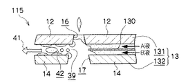
図10には、本発明の第5実施形態に係る液滴吐出ヘッド113のノズル16近傍の断面図が示されている。   FIG. 10 is a cross-sectional view of the vicinity of the nozzle 16 of the droplet discharge head 113 according to the fifth embodiment of the present invention.

本発明の第5実施形態に係る液滴吐出ヘッド113は、図10に示されているように、梁部材14の全長にわたって通風路部材40が設けられ、ノズル16の背面に設けられた開口17の近傍は通風路部材40で封止されている。   As shown in FIG. 10, the droplet discharge head 113 according to the fifth embodiment of the present invention is provided with the ventilation path member 40 over the entire length of the beam member 14, and the opening 17 provided on the back surface of the nozzle 16. Is sealed with a ventilation path member 40.

梁部材14の長手方向一方から開口17まで通風路部材40Aと梁部材14との間は吸引路42Aとして図示しない負圧発生手段と連通し矢印41Aのように開口17近傍の空気を吸引すると同時に、他方からは開口17へ空気を給送する送風路44Aとして図示しない送風ファンなどの送風手段と連通し、矢印43Aのように開口17近傍へ空気を給送する。このとき、送風路44Aの途中には第4実施形態と同様、ゴミ等を除去するフィルタや、A液、B液の乾燥を防止するため溶媒の蒸気を添加する加湿手段が設けられていてもよい。   Between the airflow path member 40A and the beam member 14 from one longitudinal direction of the beam member 14 to the opening 17, the suction path 42A communicates with a negative pressure generating means (not shown) and simultaneously sucks air near the opening 17 as indicated by an arrow 41A. From the other side, the air passage 44A for feeding air to the opening 17 communicates with a blowing means such as a blower fan (not shown), and feeds air to the vicinity of the opening 17 as indicated by an arrow 43A. At this time, similarly to the fourth embodiment, a filter for removing dust or the like, or a humidifying means for adding solvent vapor to prevent drying of the A liquid and the B liquid may be provided in the middle of the air passage 44A. Good.

さらに流路部材12の長手方向一方からノズル16まで流路部材12の全長にわたって吐出側面に通風路部材40Bが設けられ、通風路部材40Bと流路部材12との間は吸引路42Bとして図示しない負圧発生手段と連通し矢印41Bのようにノズル16近傍の空気を吸引すると同時に、他方からはノズル16へ空気を給送する送風路44Bとして図示しない送風ファンなどの送風手段と連通し、矢印43Bのようにノズル16近傍へ空気を給送する。このとき、送風路44Bの途中にもゴミ等を除去するフィルタや、A液、B液の乾燥を防止するため溶媒の蒸気を添加する加湿手段が設けられていてもよい。   Further, a ventilation path member 40B is provided on the discharge side surface over the entire length of the flow path member 12 from one longitudinal direction of the flow path member 12 to the nozzle 16, and the suction path 42B is not shown between the ventilation path member 40B and the flow path member 12. The negative pressure generating means communicates with the blowing means such as a blower fan (not shown) as the air passage 44B for sucking the air in the vicinity of the nozzle 16 as shown by the arrow 41B and at the same time supplying the air to the nozzle 16 from the other, and the arrow Air is fed to the vicinity of the nozzle 16 as in 43B. At this time, a filter for removing dust and the like in the middle of the air passage 44B, and a humidifying means for adding a vapor of a solvent to prevent drying of the liquid A and liquid B may be provided.

これによりA液、B液が混合しながら液滴2として吐出されなかった残留混合液を吸引路42Aに吸引しつつ、送風路44より清浄な空気を給送することで、ノズル16の背面に付着する虞のあるゴミ等の混入を防止する。同時にノズル16周囲の吐出面側に発生する可能性のある液溜まりを吸引路42Bに吸引しつつ、ノズル16の周囲に付着する虞のあるゴミ等の混入を防止する。   As a result, clean air is fed from the air passage 44 to the back surface of the nozzle 16 while sucking the residual mixed liquid that has not been discharged as the droplet 2 while mixing the liquid A and liquid B into the suction path 42A. Prevent contamination of dust that may adhere. At the same time, a liquid pool that may be generated on the ejection surface side around the nozzle 16 is sucked into the suction path 42B, and mixing of dust or the like that may adhere to the periphery of the nozzle 16 is prevented.

図11には、本発明の第6実施形態に係る液滴吐出ヘッド114のノズル16近傍の断面図が示されている。   FIG. 11 shows a cross-sectional view of the vicinity of the nozzle 16 of the droplet discharge head 114 according to the sixth embodiment of the present invention.

本発明の第6実施形態に係る液滴吐出ヘッド114は、図11に示されているように、梁部材14の全長にわたって通風路部材40が設けられ、ノズル16の背面に設けられた開口17の近傍は通風路部材40による封止が存在せず、開口43として大気中に開放されている。   As shown in FIG. 11, the droplet discharge head 114 according to the sixth embodiment of the present invention is provided with the ventilation path member 40 over the entire length of the beam member 14, and the opening 17 provided on the back surface of the nozzle 16. Is not sealed by the air passage member 40 and is open to the atmosphere as an opening 43.

梁部材14の長手方向一方から開口17まで、通風路部材40と梁部材14との間は吸引路42Aとして図示しない負圧発生手段と連通し、矢印41Aのように開口17近傍の空気を吸引する。同時に長手方向他方から開口17まで、通風路部材40と梁部材14との間は吸引路42Bとして図示しない負圧発生手段と連通し、矢印41Bのように開口17近傍の空気を吸引する。   From one longitudinal direction of the beam member 14 to the opening 17, the ventilation path member 40 and the beam member 14 communicate with a negative pressure generating means (not shown) as a suction path 42 </ b> A, and suck air near the opening 17 as indicated by an arrow 41 </ b> A. To do. At the same time, from the other side in the longitudinal direction to the opening 17, the air passage member 40 and the beam member 14 communicate with a negative pressure generating means (not shown) as a suction passage 42B, and suck air near the opening 17 as indicated by an arrow 41B.

これによりA液、B液が混合しながら液滴2として吐出されなかった残留混合液を吸引路42Aおよび42Bにて吸引し、ノズル16の背面に付着する虞のあるゴミ等の混入を防止する。   As a result, the remaining mixed liquid that has not been discharged as the droplet 2 while mixing the liquid A and liquid B is sucked by the suction passages 42A and 42B, thereby preventing entry of dust or the like that may adhere to the back surface of the nozzle 16. .

図12には、本発明の第7実施形態に係る液滴吐出ヘッド115のノズル16近傍の断面図が示されている。   FIG. 12 shows a cross-sectional view of the vicinity of the nozzle 16 of the droplet discharge head 115 according to the seventh embodiment of the present invention.

本発明の第7実施形態に係る液滴吐出ヘッド115は、図12に示されているように、梁部材14の吐出面側に沿って長手方向一方より流路部材12が設けられ、梁部材14との間に液流路13が形成されている。液流路13は内部で長手方向に沿って延設された仕切部材130によって液流路131、132に分割されている。   As shown in FIG. 12, the droplet discharge head 115 according to the seventh embodiment of the present invention is provided with the flow path member 12 from one side in the longitudinal direction along the discharge surface side of the beam member 14. A liquid flow path 13 is formed between the two. The liquid flow path 13 is divided into liquid flow paths 131 and 132 by a partition member 130 extending along the longitudinal direction inside.

一方、梁部材14の吐出面側に沿って長手方向他方よりノズル16まで設けられた流路部材12との間には吸引路42が形成されている。梁部材14にはノズル16の背面に開口17が設けられ、吸引路42は開口17で大気に連通している。吸引路42はノズル16の裏側で液流路13に向けて吸引口39として開口している。   On the other hand, a suction path 42 is formed between the beam member 14 and the flow path member 12 provided from the other longitudinal direction to the nozzle 16 along the discharge surface side. The beam member 14 is provided with an opening 17 on the back surface of the nozzle 16, and the suction path 42 communicates with the atmosphere through the opening 17. The suction path 42 opens as a suction port 39 toward the liquid flow path 13 on the back side of the nozzle 16.

この吸引路42は図示しない負圧発生手段(吸引ポンプなど)と連通し、負圧を印加されることにより矢印41のように吸引口39より外気を吸引する。このためA液、B液が混合しながら液滴2として吐出されなかった液滴2Bやノズル16の背面に付着する虞のあるゴミ等を吸引口39より吸引路42に吸引する。吸引口39は開口17で大気中に連通しているため、液流路13に負圧は印加されない。   This suction path 42 communicates with a negative pressure generating means (such as a suction pump) not shown, and sucks outside air from the suction port 39 as indicated by an arrow 41 when a negative pressure is applied. For this reason, the liquid 2B that has not been discharged as the liquid droplet 2 while the liquid A and the liquid B are mixed, or dust that may adhere to the back surface of the nozzle 16 is sucked into the suction path 42 from the suction port 39. Since the suction port 39 communicates with the atmosphere through the opening 17, no negative pressure is applied to the liquid flow path 13.

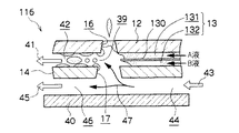
図13には、本発明の第8実施形態に係る液滴吐出ヘッド116のノズル16近傍の断面図が示されている。   FIG. 13 shows a cross-sectional view of the vicinity of the nozzle 16 of the droplet discharge head 116 according to the eighth embodiment of the present invention.

本発明の第8実施形態に係る液滴吐出ヘッド116は、図13に示されているように、梁部材14の吐出面側に沿って長手方向一方より流路部材12が設けられ、梁部材14との間に液流路13が形成されている。液流路13は内部で長手方向に沿って延設された仕切部材130によって液流路131、132に分割されている。   As shown in FIG. 13, the droplet discharge head 116 according to the eighth embodiment of the present invention is provided with the flow path member 12 from one side in the longitudinal direction along the discharge surface side of the beam member 14. A liquid flow path 13 is formed between the two. The liquid flow path 13 is divided into liquid flow paths 131 and 132 by a partition member 130 extending along the longitudinal direction inside.

一方、梁部材14の吐出面側に沿って長手方向他方よりノズル16まで設けられた流路部材12との間には吸引路42が形成されている。梁部材14にはノズル16の背面に開口17が設けられ、吸引路42は開口17を介して後述する送風路44に連通している。吸引路42はノズル16の裏側で液流路13に向けて吸引口39として開口している。   On the other hand, a suction path 42 is formed between the beam member 14 and the flow path member 12 provided from the other longitudinal direction to the nozzle 16 along the discharge surface side. The beam member 14 is provided with an opening 17 on the back surface of the nozzle 16, and the suction path 42 communicates with an air blowing path 44 described later via the opening 17. The suction path 42 opens as a suction port 39 toward the liquid flow path 13 on the back side of the nozzle 16.

また、梁部材14の吐出面裏側に沿って通風路部材40が設けられ、梁部材14との間に送風路44および回収路46が形成されている。通風路部材40は梁部材14の長手方向に沿って延設され、梁部材14のノズル16背面に設けられた開口17で吸引口39と連通している。   Further, a ventilation path member 40 is provided along the back side of the discharge surface of the beam member 14, and a blower path 44 and a recovery path 46 are formed between the beam member 14 and the ventilation path member 40. The ventilation path member 40 extends along the longitudinal direction of the beam member 14, and communicates with the suction port 39 through the opening 17 provided on the back surface of the nozzle 16 of the beam member 14.

ノズル16へ空気を給送する送風路44は図示しない送風ファンなどの送風手段と連通し、矢印43Bようにノズル16近傍へ空気を給送する。このとき、送風路44の途中にもゴミ等を除去するフィルタや、A液、B液の乾燥を防止するため溶媒の蒸気を添加する加湿手段が設けられていてもよい。   The air passage 44 for feeding air to the nozzle 16 communicates with air blowing means such as a blower fan (not shown), and feeds air to the vicinity of the nozzle 16 as indicated by an arrow 43B. At this time, a filter for removing dust and the like in the middle of the air passage 44 and a humidifying means for adding a vapor of a solvent to prevent drying of the liquid A and liquid B may be provided.

吸引路42は図示しない負圧発生手段(吸引ポンプなど)と連通し、負圧を印加されることにより矢印41のように吸引口39よりノズル16近傍の空気を吸引する。このためA液、B液が混合しながら液滴2として吐出されなかった液滴2Bやノズル16の背面に付着する虞のあるゴミ等を吸引口39より吸引路42に吸引する。また、開口17を通じて送風路44より給送された空気を矢印47のように吸引する。   The suction path 42 communicates with a negative pressure generating means (such as a suction pump) (not shown), and sucks air near the nozzle 16 from the suction port 39 as indicated by an arrow 41 when a negative pressure is applied. For this reason, the liquid 2B that has not been discharged as the liquid droplet 2 while the liquid A and the liquid B are mixed, or dust that may adhere to the back surface of the nozzle 16 is sucked into the suction path 42 from the suction port 39. Further, the air fed from the air blowing path 44 through the opening 17 is sucked as indicated by an arrow 47.

一方、回収路46は図示しない循環ポンプなどのような回収手段と連通し、矢印45のようにノズル16近傍の空気を一旦吸引すると同時に、送風路44あるいは送風手段に連通することで、空気を循環させる。   On the other hand, the collection path 46 communicates with a collection means such as a circulation pump (not shown), and once sucks air near the nozzle 16 as indicated by an arrow 45, and at the same time communicates with the blow path 44 or the blow means, Circulate.

<その他>
尚、本発明は、上記の実施の形態に限定されるものではない。例えば、上記実施の形態では、A液、B液をノズル近傍で混合する2液混合とされているが、3液またはそれ以上の液を混合する構成であっても良い。
<Others>
In addition, this invention is not limited to said embodiment. For example, in the above-described embodiment, the two liquid mixing is performed in which the A liquid and the B liquid are mixed in the vicinity of the nozzle.

また、本明細書における液滴吐出ヘッドはインクジェット記録ヘッドを例にあげているが、必ずしもインクを用いた記録紙上への文字や画像の記録に限定されるものではない。すなわち、記録媒体は紙に限定されるものでなく、また吐出される液体もインクに限定されるものではない。例えば、高分子フィルムやガラス上に液を吐出してディスプレイ用カラーフィルターを作成したり、液状の半田を基板上に吐出して部品実装用のバンプを形成したりするなど、工業用的に用いられる液滴噴射装置全般に対して本発明を利用することが可能である。   In addition, although the ink jet recording head is taken as an example of the droplet discharge head in the present specification, it is not necessarily limited to recording characters and images on recording paper using ink. That is, the recording medium is not limited to paper, and the ejected liquid is not limited to ink. For example, it is used industrially, for example, to create a color filter for display by discharging liquid onto a polymer film or glass, or to form bumps for component mounting by discharging liquid solder onto a substrate. The present invention can be applied to all types of liquid droplet ejecting apparatuses.

本発明に係る液滴吐出ヘッドの構造を示す側面図、断面図および斜視図である。FIG. 3 is a side view, a cross-sectional view, and a perspective view showing a structure of a droplet discharge head according to the present invention. 本発明に係る液滴吐出ヘッドの動作を示す側面図である。It is a side view which shows operation | movement of the droplet discharge head which concerns on this invention. 本発明に係る液滴吐出ヘッドの動作を示す側面図である。It is a side view which shows operation | movement of the droplet discharge head which concerns on this invention. 本発明に係る液滴吐出ヘッドの動作を示す側面図である。It is a side view which shows operation | movement of the droplet discharge head which concerns on this invention. 本発明に係る液滴吐出ヘッドのノズル近傍における構造を示す斜視図および断面図である。FIG. 4 is a perspective view and a cross-sectional view showing a structure in the vicinity of a nozzle of a droplet discharge head according to the present invention. 本発明に係る液滴吐出ヘッドの製造工程を示す斜視図である。It is a perspective view which shows the manufacturing process of the droplet discharge head which concerns on this invention. 本発明の第2実施形態に係る液滴吐出ヘッドのノズル近傍における構造を示す斜視図および断面図である。It is the perspective view and sectional drawing which show the structure in the nozzle vicinity of the droplet discharge head which concerns on 2nd Embodiment of this invention. 本発明の第3実施形態に係る液滴吐出ヘッドのノズル近傍における構造を示す斜視図および断面図である。It is the perspective view and sectional view which show the structure in the nozzle vicinity of the droplet discharge head which concerns on 3rd Embodiment of this invention. 本発明の第4実施形態に係る液滴吐出ヘッドのノズル近傍における構造を示す断面図である。It is sectional drawing which shows the structure in the nozzle vicinity of the droplet discharge head which concerns on 4th Embodiment of this invention. 本発明の第5実施形態に係る液滴吐出ヘッドのノズル近傍における構造を示す断面図である。It is sectional drawing which shows the structure in the nozzle vicinity of the droplet discharge head which concerns on 5th Embodiment of this invention. 本発明の第6実施形態に係る液滴吐出ヘッドのノズル近傍における構造を示す断面図である。It is sectional drawing which shows the structure in the nozzle vicinity of the droplet discharge head which concerns on 6th Embodiment of this invention. 本発明の第7実施形態に係る液滴吐出ヘッドのノズル近傍における構造を示す断面図である。It is sectional drawing which shows the structure in the nozzle vicinity of the droplet discharge head which concerns on 7th Embodiment of this invention. 本発明の第8実施形態に係る液滴吐出ヘッドのノズル近傍における構造を示す断面図である。It is sectional drawing which shows the structure in the nozzle vicinity of the droplet discharge head which concerns on 8th Embodiment of this invention.

符号の説明Explanation of symbols

2 液滴
10 液滴吐出ヘッド
12 流路部材
13 流液路
14 梁部材
16 ノズル
17 開口
18 支持部材
20 回転エンコーダ
30 ピエゾ素子
36 アクチュエータ
39 吸引口
40 通風路部材
42 吸引路
44 送風路
46 回収路
50 レーザ
130 仕切部材
131 液流路
132 液流路
2 Droplet 10 Droplet discharge head 12 Flow path member 13 Flow liquid path 14 Beam member 16 Nozzle 17 Opening 18 Support member 20 Rotary encoder 30 Piezo element 36 Actuator 39 Suction port 40 Ventilation path member 42 Suction path 44 Blower path 46 Collection path 50 Laser 130 Partition member 131 Liquid flow path 132 Liquid flow path

Claims (7)

液滴を吐出するノズルと、
混合により粘度が増加する少なくとも2種類の液体が前記ノズルに向けて別々に供給される液体流路部材と、
前記液体流路部材と接合もしくは液体流路部材を含み、液滴吐出面に凹となるように座屈反転変形した後、液滴吐出方向に凸となるよう座屈反転変形し、前記ノズル近傍の液体に吐出方向の慣性を与えることにより、前記ノズルの近傍で混合された混合液の液滴を前記ノズルより吐出させる梁部材と、を備えた液滴吐出ヘッド。
A nozzle for discharging droplets;
A liquid flow path member to which at least two kinds of liquids whose viscosity is increased by mixing are separately supplied toward the nozzle;
In the vicinity of the nozzle, including the liquid flow path member or including the liquid flow path member, buckling and reversing deformation so as to be concave on the droplet discharge surface, and then buckling and reversing deformation so as to be convex in the droplet discharge direction. And a beam member that discharges droplets of the mixed liquid mixed in the vicinity of the nozzles from the nozzles by applying inertia in the discharge direction to the liquid.
前記液体流路部材の両端部からそれぞれ種類の異なる液体が前記ノズルに向けて供給される請求項1に記載の液滴吐出ヘッド。 The liquid droplet ejection head according to claim 1, wherein different types of liquid are supplied toward the nozzles from both ends of the liquid flow path member. 前記液体流路部材の流路は、長手方向に沿って仕切部材で仕切られている請求項1または請求項2に記載の液滴吐出ヘッド。 The droplet discharge head according to claim 1, wherein the flow path of the liquid flow path member is partitioned by a partition member along a longitudinal direction. 前記梁部材あるいは前記梁部材および前記液体流路部材は、前記ノズルより溢れた液体を液滴吐出方向の反対側に排出する液体排出部を備えた請求項1〜請求項3の何れか1項に記載の液滴吐出ヘッド。 The said beam member or the said beam member and the said liquid flow path member are provided with the liquid discharge part which discharges | emits the liquid overflowing from the said nozzle to the other side of a droplet discharge direction. The droplet discharge head described in 1. 吸引口が前記ノズルの近傍に向いた吸引路と、
前記吸引路に負圧を発生させる負圧発生手段と、
を備えた請求項4に記載の液滴吐出ヘッド。
A suction path whose suction port faces the vicinity of the nozzle;
Negative pressure generating means for generating a negative pressure in the suction path;
A droplet discharge head according to claim 4, comprising:
前記吸引路の前記吸引口へ空気を送る送風路と、
前記送風路に正圧を発生させる送風手段と、
を備えた請求項5に記載の液滴吐出ヘッド。
A blower path for sending air to the suction port of the suction path;
A blowing means for generating a positive pressure in the blowing path;
A droplet discharge head according to claim 5, comprising:
請求項1〜請求項6の何れか1項に記載の液滴吐出ヘッドを備えた液滴吐出装置。 A droplet discharge device comprising the droplet discharge head according to claim 1.
JP2008322134A 2008-12-18 2008-12-18 Liquid jetting head and liquid jetting device Withdrawn JP2010143049A (en)

Priority Applications (1)

Application Number Priority Date Filing Date Title
JP2008322134A JP2010143049A (en) 2008-12-18 2008-12-18 Liquid jetting head and liquid jetting device

Applications Claiming Priority (1)

Application Number Priority Date Filing Date Title
JP2008322134A JP2010143049A (en) 2008-12-18 2008-12-18 Liquid jetting head and liquid jetting device

Publications (1)

Publication Number Publication Date
JP2010143049A true JP2010143049A (en) 2010-07-01

Family

ID=42563982

Family Applications (1)

Application Number Title Priority Date Filing Date
JP2008322134A Withdrawn JP2010143049A (en) 2008-12-18 2008-12-18 Liquid jetting head and liquid jetting device

Country Status (1)

Country Link
JP (1) JP2010143049A (en)

Similar Documents

Publication Publication Date Title
JP7069875B2 (en) Liquid discharge head and liquid discharge device
US8123335B2 (en) Liquid droplet ejecting head and liquid droplet ejecting apparatus
JP3675272B2 (en) Liquid discharge head and method for manufacturing the same
CN109203678B (en) Liquid ejection head and liquid ejection apparatus
CN103025530A (en) Fluid ejection assembly with circulation pump
JP2010201872A (en) Fluid injection device and control method therefor
US10882316B2 (en) Liquid ejecting head and liquid ejecting apparatus
JP5107891B2 (en) Droplet ejection device
JP2005254579A (en) Droplet ejector
JP2016055555A (en) Liquid discharge device
JP2010143049A (en) Liquid jetting head and liquid jetting device
JP2002321354A (en) Ink jet recording head and ink jet recording apparatus
JP2000158657A (en) Ink jet print head and ink jet printing device mounting the head
JP2001277499A (en) Inkjet recording head
JP2006130682A (en) Liquid discharge head and recording apparatus
CN100446976C (en) drip ejector assembly
JPH05293963A (en) Inkjet printer head
CN100453321C (en) drip ejector assembly
JP2012111087A (en) Liquid jet head and liquid jet apparatus
JP2002240279A (en) Ink jet head and ink jet recording apparatus
JP4353290B2 (en) Liquid ejector
JP2008307840A (en) Liquid ejector
US10807363B2 (en) Liquid ejecting head and liquid ejecting apparatus
JP2003266689A (en) Droplet discharge head, method of manufacturing the same, and ink jet recording apparatus
JP7309359B2 (en) Liquid ejector

Legal Events

Date Code Title Description
A761 Written withdrawal of application

Free format text: JAPANESE INTERMEDIATE CODE: A761

Effective date: 20110216