JP2010142852A - Press machine, method for discriminating the bottom dead center position thereof and adjustment method therefor - Google Patents
Press machine, method for discriminating the bottom dead center position thereof and adjustment method therefor Download PDFInfo
- Publication number
- JP2010142852A JP2010142852A JP2008324363A JP2008324363A JP2010142852A JP 2010142852 A JP2010142852 A JP 2010142852A JP 2008324363 A JP2008324363 A JP 2008324363A JP 2008324363 A JP2008324363 A JP 2008324363A JP 2010142852 A JP2010142852 A JP 2010142852A
- Authority
- JP
- Japan
- Prior art keywords
- dead center
- bottom dead
- center position
- slide
- protrusions
- Prior art date
- Legal status (The legal status is an assumption and is not a legal conclusion. Google has not performed a legal analysis and makes no representation as to the accuracy of the status listed.)
- Pending
Links
- 238000000034 method Methods 0.000 title claims abstract description 34
- 238000003825 pressing Methods 0.000 claims abstract description 18
- 230000009471 action Effects 0.000 claims abstract description 16
- 238000012545 processing Methods 0.000 claims description 71
- 230000007246 mechanism Effects 0.000 claims description 11
- 238000013461 design Methods 0.000 claims description 5
- 239000000463 material Substances 0.000 description 11
- 230000013011 mating Effects 0.000 description 8
- 239000002184 metal Substances 0.000 description 6
- 230000008569 process Effects 0.000 description 5
- 238000012937 correction Methods 0.000 description 4
- 230000008859 change Effects 0.000 description 3
- 238000003754 machining Methods 0.000 description 3
- 238000005452 bending Methods 0.000 description 2
- 238000005516 engineering process Methods 0.000 description 2
- 238000003384 imaging method Methods 0.000 description 2
- 238000005259 measurement Methods 0.000 description 2
- 238000004080 punching Methods 0.000 description 2
- 230000004044 response Effects 0.000 description 2
- 238000010008 shearing Methods 0.000 description 2
- 229910000831 Steel Inorganic materials 0.000 description 1
- 230000015572 biosynthetic process Effects 0.000 description 1
- 238000006243 chemical reaction Methods 0.000 description 1
- 238000007796 conventional method Methods 0.000 description 1
- 230000007423 decrease Effects 0.000 description 1
- 230000003247 decreasing effect Effects 0.000 description 1
- 238000006073 displacement reaction Methods 0.000 description 1
- 238000007689 inspection Methods 0.000 description 1
- 238000004519 manufacturing process Methods 0.000 description 1
- 238000012986 modification Methods 0.000 description 1
- 230000004048 modification Effects 0.000 description 1
- 238000007781 pre-processing Methods 0.000 description 1
- 230000009467 reduction Effects 0.000 description 1
- 239000010959 steel Substances 0.000 description 1
- 238000012546 transfer Methods 0.000 description 1
- 238000012795 verification Methods 0.000 description 1
Images


Landscapes
- Control Of Presses (AREA)
Abstract
Description
本発明は、曲げ加工、打ち抜き加工および絞り加工等に用いられるプレス機の下死点位置が適正か否かを判定する方法、下死点の調整方法およびこれら方法を実施するのに好適なプレス機に関する。 The present invention relates to a method for determining whether or not the bottom dead center position of a press machine used for bending, punching, drawing, etc. is appropriate, a method for adjusting bottom dead center, and a press suitable for carrying out these methods. Related to the machine.
プレス機を用いた精密加工では、製品精度は、プレス機、該プレス機のボルスタおよび該ボルスタに近づく方向およびこれから離れる方向へ移動するスライドにそれぞれ取り付けられる一対の金型(上金型および下金型)および被加工材である材料のそれぞれの精度に影響を受ける。 In precision machining using a press machine, the product accuracy is determined by the press machine, the bolster of the press machine, and a pair of molds (upper mold and lower mold) attached to the slide moving in the direction approaching and away from the bolster. Mold) and the accuracy of the material being processed.
プレス機に関しては、上金型が取り付けられるスライドの下死点位置の設定が重要となる。このスライドの下死点位置の設定のために、一般的には、実際の製品の撮影画像から該製品の精度を計測し、そのデータに基づいてスライドの下死点位置が適正値に設定されている(例えば、非特許文献1参照)。 Regarding the press machine, it is important to set the bottom dead center position of the slide to which the upper mold is attached. In order to set the bottom dead center position of this slide, generally, the accuracy of the product is measured from a photographed image of the actual product, and the bottom dead center position of the slide is set to an appropriate value based on the data. (For example, refer nonpatent literature 1).
しかしながら、プレス機は、その作動中の温度変化によってスライドの下死点位置に変化を生じることがあり、また、プレス機に取り付けられた金型の温度変化によっても実質的にスライドの下死点位置に変化を生じることがある。 However, the press machine may change the bottom dead center position of the slide due to the temperature change during its operation, and the slide bottom dead center is also substantially changed by the temperature change of the mold attached to the press machine. Changes in position may occur.
したがって、プレス機の始動時に、従来の前記した下死点位置の調整方法を用いて、たとえ適正な下死点位置に設定しても、該下死点位置にずれが生じることがある。ところが、この下死点位置のずれによって製品精度が低下しても、従来では、このずれを確認するためには、その都度、前記したような実際の製品の撮影画像を不可欠とする判定作業が必要となる。 Therefore, when the press machine is started, even if it is set to an appropriate bottom dead center position using the conventional method for adjusting the bottom dead center position, the bottom dead center position may be displaced. However, even if the accuracy of the product is reduced due to the shift of the bottom dead center position, conventionally, in order to confirm this shift, a determination operation that makes it necessary to take a photographed image of the actual product as described above is necessary. Necessary.
この製品の撮影画像に基づく精度判定では、実際の製品を写真撮影するについて、製品のいずれの部分をいずれの方向から撮影するかを製品毎に検証して決める必要があり、その判定は製品の形状および材質毎に必要となる。そのため、実際の製品の撮影画像を不可欠とする前記したような判定作業では、製品の精度判定を迅速かつ簡易的に行うことはできなかった。 In the accuracy judgment based on the photographed image of this product, it is necessary to verify and determine for each product which part of the product is photographed from which direction when photographing the actual product. Required for each shape and material. For this reason, in the above-described determination work in which a photographed image of an actual product is indispensable, the accuracy of the product cannot be determined quickly and easily.
しかも、前記した製品の撮影画像に基づく従来の判定方法では、下死点位置のずれに起因して製品精度が低下したことが煩雑な検証を伴う精度測定によってたとえ判定できたとしても、下死点位置のずれが上方および下方のいずれの方向にどの程度ずれているのかを知るには、熟練および経験を必要とし、その調整にも熟練と経験とを要した。また、製品の撮影画像の情報に基づいて下死点位置を自動調整するためには、高価で複雑な画像処理装置や電子制御機器が必要となった。 In addition, in the conventional determination method based on the photographed image of the product described above, even if it is possible to determine that the product accuracy has deteriorated due to the shift of the bottom dead center position by accuracy measurement with complicated verification, In order to know how much the position of the point is shifted in the upward or downward direction, skill and experience are required, and the adjustment also requires skill and experience. Further, in order to automatically adjust the bottom dead center position based on the information of the photographed image of the product, an expensive and complicated image processing apparatus and electronic control device are required.
そのため、製品精度に大きな影響を与えるプレス機の下死点位置が適正であるか否かを従来に比較して容易かつ簡易に判定し、あるいはこの判定に基づいて容易に下死点位置を適正に調整することが望まれていた。 Therefore, it is easier and simpler to determine whether the bottom dead center position of a press that has a major impact on product accuracy is appropriate, or the bottom dead center position is easily determined based on this determination. It was desired to adjust to.
よって、本発明の目的は、プレス機による実際の製品の精度を計測することなく、容易かつ迅速にプレス機の下死点位置が適正位置にあるか否かを判定する方法および容易かつ迅速に下死点位置を適正位置に調整する方法、さらには本発明の方法を実施するのに好適なプレス機を提供することにある。 Therefore, an object of the present invention is to easily and quickly determine whether or not the bottom dead center position of the press machine is in an appropriate position and easily and quickly without measuring the accuracy of the actual product by the press machine. Another object of the present invention is to provide a press machine suitable for carrying out the method of adjusting the bottom dead center position to an appropriate position, and further the method of the present invention.
本発明に係る方法は、ボルスタに近づく方向およびこれから離れる方向へ移動可能のスライドを備えるプレス機における前記スライドの下死点位置が適正であるか否かを判定する方法であって、前記ボルスタおよび前記スライドに取り付けられた一対の加工部の少なくとも一方に形成された刻印部分により、前記スライドの単一ストロークでの下死点位置で定位置にある被加工材の非製品領域に、前記刻印部分の押圧作用でもってマークを形成し、前記下死点位置で形成された前記マークの情報に基づいて前記スライドの下死点位置が適正であるか否かを判定することを特徴とする。 The method according to the present invention is a method for determining whether or not a bottom dead center position of the slide is appropriate in a press machine provided with a slide movable in a direction approaching and away from the bolster, the bolster and The stamped portion is formed on at least one of a pair of processed portions attached to the slide to the non-product region of the workpiece at a bottom dead center position in a single stroke of the slide. A mark is formed by the pressing action of, and it is determined whether or not the bottom dead center position of the slide is appropriate based on the information of the mark formed at the bottom dead center position.
本発明に係る前記方法によれば、前記プレス機のスライドの下死点位置が適正位置にあるときに前記被加工材の非製品領域に形成される前記マークの情報、例えばマークの平面形状あるいはマーク数等の情報が求められる。このマーク情報を基準値と比較することにより、判定作業毎に従来のような加工製品の画像情報を得ることなく、前記下死点位置が適正か否か判定することができる。 According to the method of the present invention, information on the mark formed in a non-product area of the workpiece when the bottom dead center position of the slide of the press machine is at an appropriate position, for example, the planar shape of the mark or Information such as the number of marks is required. By comparing this mark information with a reference value, it is possible to determine whether or not the bottom dead center position is appropriate without obtaining image information of a processed product as in the past for each determination operation.
前記刻印部分は、高さ寸法を異にする複数の突部または深さ寸法を異にする複数の凹部で構成することができる。この場合、前記スライドの単一ストロークでの下死点位置で定位置にある被加工材の非製品領域に、前記刻印部分の押圧作用でもって前記突部または凹部に対応したマークが形成されるので、前記下死点位置で形成された前記マークの数に基づいて前記スライドの下死点位置が適正であるか否かを判定することができる。 The marking portion may be composed of a plurality of protrusions having different height dimensions or a plurality of recesses having different depth dimensions. In this case, a mark corresponding to the protruding portion or the recessed portion is formed in the non-product region of the workpiece at a fixed position at the bottom dead center position in the single stroke of the slide by the pressing action of the stamped portion. Therefore, it can be determined whether or not the bottom dead center position of the slide is appropriate based on the number of the marks formed at the bottom dead center position.
前記突部または凹部に対応して形成される前記マーク数についての基準値は、予め求められる。すなわち、基準値となる所定のマーク数は、前記した従来技術による製品の撮影画像の画像処理を用いた手法によって求めることができる。あるいは、これに代えて、後述するような被加工材への加工内容やプレス機の特性に基づいて、設定することができる。いずれにしても、一旦、適正な所定のマーク数を知ることができると、高さ寸法を異にする複数の突部または深さ寸法を異にする複数の凹部を有する刻印部分の押圧作用でもって前記被加工材のプレス加工時に前記突部または凹部に対応して前記被加工部材の非製品領域に形成される前記マーク数が所定数であるか否かを判定することにより、前記下死点位置の適正値からのずれの有無を極めて容易に判定することができる。 A reference value for the number of marks formed corresponding to the protrusions or recesses is obtained in advance. That is, the predetermined number of marks serving as the reference value can be obtained by a technique using image processing of a captured image of a product according to the above-described conventional technology. Or it can replace with this and can set based on the content of processing to a processed material and the characteristic of a press as mentioned below. In any case, once the proper predetermined number of marks can be known, the pressing action of the marking portion having a plurality of protrusions having different height dimensions or a plurality of recesses having different depth dimensions. Accordingly, by determining whether or not the number of the marks formed in the non-product region of the workpiece corresponding to the protrusion or the recess during the pressing of the workpiece is a predetermined number, The presence or absence of deviation from the appropriate value of the point position can be determined very easily.
すなわち、前記刻印部分が例えば高さ寸法を異にする複数の突部を有する場合、プレス加工時、所定の高さ寸法以上の高さを有する前記突部の押圧作用により、当該突部の数に対応した所定数の前記凹所が前記マークとして前記被加工部材の非製品領域に形成される。しかし、下死点位置が前記適正位置から上方にずれると、高さ寸法の小さな順で、前記突部による押圧作用が失われることから、この場合、前記被加工材の非製品領域に形成される前記凹所の個数が減少する。これとは逆に、下死点位置が前記適正位置から下方にずれると、前記所定の高さよりも低い前記突部が押圧作用を発揮することから、前記押圧作用を生じる突部数の増大に伴って前記非製品領域に形成される前記凹所の個数が増大する。 That is, when the stamped portion has, for example, a plurality of protrusions having different height dimensions, the number of protrusions due to the pressing action of the protrusions having a height equal to or higher than a predetermined height dimension during pressing. A predetermined number of the recesses corresponding to is formed in the non-product area of the workpiece as the mark. However, if the bottom dead center position is shifted upward from the appropriate position, the pressing action by the protrusions is lost in the order of decreasing height dimension, and in this case, it is formed in the non-product region of the workpiece. The number of the recesses decreases. On the contrary, when the bottom dead center position is shifted downward from the appropriate position, the protrusion lower than the predetermined height exerts the pressing action, so that the number of protrusions causing the pressing action increases. Thus, the number of the recesses formed in the non-product area increases.
したがって、前記したように、例えば被加工材の材質や加工内容に応じて、最適な下死点位置では前記刻印部分の前記突部または凹部によって前記被加工材の非製品領域に何個のマークが形成されるかを予め求めておくことにより、例えば前記マークの数を目視で確認し、その数を所定数と比較することにより、実際の製品の精度を計測することなく、プレス機のスライドの下死点位置が適正であるか否かを判定することができる。 Therefore, as described above, the number of marks in the non-product area of the workpiece by the protrusion or recess of the stamped portion at the optimum bottom dead center position, for example, depending on the material of the workpiece and the processing content For example, by visually checking the number of the marks and comparing the number with a predetermined number, the slide of the press machine is measured without measuring the accuracy of the actual product. It is possible to determine whether or not the bottom dead center position is appropriate.
また、本発明によれば、前記下死点位置で形成された前記マークの情報に基づいて前記スライドの下死点位置を調整することを特徴とする、プレス機の下死点位置の調整方法が提供される。 According to the present invention, the bottom dead center position of the press is adjusted based on the information of the mark formed at the bottom dead center position. Is provided.
例えば、前記刻印部分が前記したように高さ寸法を異にする複数の突部あるいは深さ寸法を異にする複数の凹部で構成される場合、各突部または凹部で形成される前記マークの数が所定値よりも多いかあるいは少ないかにより、下死点位置が上下のいずれの方向にずれているかを容易に判定することができるので、前記マーク数の情報に基づいて、予め前記突部のそれぞれの高さ寸法差あるいは前記凹部のそれぞれの深さ寸法差を把握しておくことにより、前記マークの数から適正な下死点位置への必要調整量を容易に推定することができ、この情報に基づいて容易に下死点位置を適正値に調整することが可能となる。 For example, when the engraved portion is composed of a plurality of protrusions having different height dimensions or a plurality of recesses having different depth dimensions as described above, the mark formed on each protrusion or recess Depending on whether the number is larger or smaller than a predetermined value, it is possible to easily determine in which direction the bottom dead center position is shifted in the vertical direction. By grasping each height dimension difference or each depth dimension difference of the recess, it is possible to easily estimate the necessary adjustment amount to the appropriate bottom dead center position from the number of the marks, Based on this information, the bottom dead center position can be easily adjusted to an appropriate value.
さらに、本発明に係るプレス機は、相対的に近づく方向および離れる方向へ移動可能の上金型のような上加工部および下金型のような下加工部を有し、前記両加工部の少なくとも一方の面には、前記上加工部の下死点位置で定位置にある被加工材の非製品領域に凹所を形成すべく高さ寸法を異にする複数の突部または深さ寸法を異にする複数の凹部を有する刻印部分が形成されていることを特徴とする。 Furthermore, the press according to the present invention has an upper working part such as an upper mold and a lower working part such as a lower mold that are movable in a relatively approaching direction and a separating direction. On at least one surface, a plurality of protrusions or depth dimensions having different height dimensions so as to form a recess in a non-product region of the workpiece at a fixed position at the bottom dead center position of the upper processed portion A marking portion having a plurality of recesses having different diameters is formed.
本発明に係るプレス機によれば、前記したように、前記被加工材の非製品領域に形成される前記マークの数の情報から、下死点位置が適正であるか否かを知ることができ、また前記マーク数の情報に基づいて下死点位置を適正値に調整できることから、本発明に係る前記両方法を容易かつ確実に実行することができる。 According to the press according to the present invention, as described above, it is possible to know whether the bottom dead center position is appropriate from the information on the number of the marks formed in the non-product area of the workpiece. In addition, since the bottom dead center position can be adjusted to an appropriate value based on the information on the number of marks, both the methods according to the present invention can be executed easily and reliably.
前記刻印部分が前記突部を有する場合、該各突部は、所定値毎の高低差を有することができる。前記各突部の高低差が例えば2μmでありかつ被加工材に当該突部による4つの凹所が観察されたときにスライドあるいは該スライドに取り付けられた金型が適正な下死点位置にあると判断できる場合、実際に2個の前記凹所が観察されたときは、下死点位置を4μm下方に移動させる必要があると判定できる。 When the marking portion has the protrusions, the protrusions can have a height difference for each predetermined value. When the height difference between the protrusions is 2 μm, for example, and the four recesses due to the protrusions are observed on the workpiece, the slide or the die attached to the slide is at an appropriate bottom dead center position. If two recesses are actually observed, it can be determined that it is necessary to move the bottom dead center position downward by 4 μm.
前記突部は、全体に矩形の横断面形状を有し、平坦な矩形頂面を有するように形成することができる。この複数の突部は、該突部間にスペースを設けることなく階段状に隣接して並列的に連続して形成することができる。 The protrusion may have a rectangular cross-sectional shape as a whole and may have a flat rectangular top surface. The plurality of protrusions can be formed continuously in parallel adjacent to each other without providing a space between the protrusions.
この突部は、製品のための上金型あるいは下金型の合わせ面、すなわち被加工材の非製品領域に対応する平坦面部分に形成することができる。上金型および下金型の一方に前記刻印部分として複数の突部を形成した場合、他方の金型の前記刻印部分に対応する面部分は、平坦面とすることができる。 This protrusion can be formed on the mating surface of the upper mold or the lower mold for the product, that is, on the flat surface portion corresponding to the non-product region of the workpiece. When a plurality of protrusions are formed as the marking portion on one of the upper die and the lower die, the surface portion corresponding to the marking portion of the other die can be a flat surface.
また、前記刻印部分は、製品加工のための上金型あるいは下金型に形成することに代えて、刻印部分のための専用金型に形成することができる。この専用金型の刻印部分が形成される面は、前記製品加工のための上金型あるいは下金型の合わせ面と同一レベルに設定される。前記専用金型を用いることにより、前記製品のための上金型あるいは下金型の製作費の増大を防止することができる。 Further, the stamped portion can be formed in a dedicated die for the stamped portion instead of being formed in the upper die or the lower die for product processing. The surface on which the stamped portion of the dedicated mold is formed is set at the same level as the mating surface of the upper mold or the lower mold for processing the product. By using the dedicated mold, it is possible to prevent an increase in the manufacturing cost of the upper mold or the lower mold for the product.
前記刻印部分の前記複数の突部あるいは凹部は、前記被加工材の前記非製品領域に対応する領域で、高さ順あるいは深さ順に整列するように形成することが望ましい。 It is desirable that the plurality of protrusions or recesses of the marking portion be formed so as to be aligned in order of height or depth in a region corresponding to the non-product region of the workpiece.
さらに、本発明に係るプレス機は、前記上加工部である上金型の下死点を調整するための調整機構を含むことができる。前記被加工材の前記非製品領域に形成された前記凹所の個数に応じて前記調整機構を作動させることができる。 Furthermore, the press according to the present invention can include an adjusting mechanism for adjusting the bottom dead center of the upper die that is the upper processing portion. The adjustment mechanism can be operated according to the number of the recesses formed in the non-product region of the workpiece.
さらに、本発明に係るプレス機は、前記刻印部により前記被加工材に形成された凹所を撮影するための撮影手段を有する画像処理装置と、該画像処理装置により得られた画像から前記凹所の個数を求める演算処理装置とを含むことができる。該演算処理装置により求められた前記凹所の個数に応じて前記調整機構を作動させることにより、人手による目視を不要として、自動的に下死点位置を最適に調整することができる。 Furthermore, the press machine according to the present invention includes an image processing device having a photographing means for photographing the recess formed in the workpiece by the marking portion, and the concave portion from the image obtained by the image processing device. And an arithmetic processing unit for obtaining the number of locations. By operating the adjusting mechanism in accordance with the number of the recesses determined by the arithmetic processing unit, it is possible to automatically adjust the bottom dead center position automatically without the need for manual inspection.
本発明に係る前記撮影手段は、従来のような製品の複雑な画像を得るためのものではなく、前記刻印部分の前記突部または凹部によって前記被加工材に形成さえれる凹所を撮影することから、その撮影画像を処理する前記画像処理装置および演算処理装置に求められる機能も製品の画像を取り扱う従来装置に比較してその負荷が著しく軽減される。したがって、従来に比較して極めて安価にこれら撮影手段、画像処理装置および演算処理装置を含む自動制御システムを構成することが可能となる。 The imaging means according to the present invention is not for obtaining a complex image of a product as in the prior art, but for imaging a recess that can be formed in the workpiece by the protrusion or recess of the stamped portion. Therefore, the function required for the image processing apparatus and the arithmetic processing apparatus for processing the photographed image is remarkably reduced as compared with the conventional apparatus for handling product images. Therefore, it is possible to configure an automatic control system including these photographing means, image processing apparatus, and arithmetic processing apparatus at an extremely low cost as compared with the prior art.
本発明によれば、前記したように、被加工材の非製品領域に形成されるマーク情報によって、プレス機の下死点位置が適正であるか否かを判定することができるので、プレス加工を受けた実際の製品の精度を計測することなく、迅速かつ容易に適正に下死点位置が適正であるか否かを判定することができる。 According to the present invention, as described above, it is possible to determine whether or not the bottom dead center position of the press machine is appropriate based on the mark information formed in the non-product area of the workpiece. It is possible to determine whether or not the bottom dead center position is appropriate, promptly and easily, without measuring the accuracy of the actual product received.
さらに、前記刻印部分を高さ寸法の異なる複数の突部または深さ寸法の異なる凹部で構成し、また、予め前記刻印部分の前記突部の高さ寸法あるいは凹部の深さ寸法についての情報を得ておくことにより、前記マークの数情報に基づいて下死点位置を適正値に調整することができる。したがって、比較的簡単な構成で迅速かつ容易に高品質のプレス製品を得ることができる。 Further, the stamped portion is constituted by a plurality of protrusions having different height dimensions or recesses having different depth dimensions, and information on the height dimension of the protrusion or the depth dimension of the recess of the stamped portion in advance. By obtaining the information, the bottom dead center position can be adjusted to an appropriate value based on the number information of the marks. Therefore, a high-quality press product can be obtained quickly and easily with a relatively simple configuration.
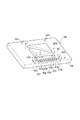
本発明に係る方法の実施に好適なプレス機10は、図1に示されているように、ボルスタ12が設けられる下部フレーム14と、該下部フレームに間隔をおいて支持された上部フレーム16とを含む。ボルスタ12上には、金型18の下型18aが載置される。上部フレーム16には、従来よく知られているように、例えばクランク機構のような運動変換機構を介して、スライド20をその上死点と下死点との間で往復運動させる往復運動装置22が搭載されている。スライド20の下面には、金型18の上型18bが下方の下型18aに対向して取り付けられており、上型18bは、往復運動装置22の作動により、下型18aに向けおよびこれから離れる方向へ往復運動する。下型18aおよび上型18bは、下加工部および上加工部をそれぞれ構成し、両型18a、18bはプレス機10の加工部を構成する。
As shown in FIG. 1, a
金型18の両型18a、18bの互いに対向する平坦な合わせ面24間には、フィーダ26を経て帯状の鋼材のような被加工材28が間歇的に供給される。往復運動装置22は、被加工材28の前記した間歇供給に同期して上型18bを下型18aへ向けおよびこれから離れる方向へ往復運動させる。この往復運動により、被加工材28は、下型18aおよび上型18bの押圧作用により、該両型の合わせ面24間で、該合わせ面24に形成された互いに対応する型面部分24a(図2参照)に応じた加工を受ける。
A
この加工には、例えば絞り加工、曲げ加工、抜き加工、つぶし加工あるいは剪断加工のような機械プレス加工が含まれるが、いずれにしても製品の加工精度は、上型18bが取り付けられるスライド20の下死点の高さ位置に大きな影響を受ける。剪断加工では、切断面の加工精度が下死点の高さ位置に大きな影響を受ける。また、プレス機10が剪断機である場合、下加工部は下刃を意味し、上加工部は上刃を意味する。このようなプレス機10には、往復運動装置22に関連して前記下死点位置を調整するための従来よく知られたサーボモータ30が設けられている。
This processing includes mechanical press processing such as drawing processing, bending processing, punching processing, crushing processing, or shearing processing. In any case, the processing accuracy of the product is that of the
サーボモータ30は、制御装置32の制御を受ける。この制御装置32は、基本的には、カメラ34aで得られた撮影画像を取り扱うための画像処理装置34と、該画像処理装置により得られた画像情報に基づいて適正な制御信号を生成する演算処理装置36と、該演算処理装置により得られた前記制御信号で前記サーボモータ30の作動を制御するサーボモータ制御回路38とを備える。
The
カメラ34aは、例えばCCDのようなデジタルカメラからなり、被加工材28の金型18を経た部分を撮影するように、下部フレーム14に支持される。カメラ34aは、プレス機10の外方に搬出された被加工材28を撮影すべくプレス機10の外方に設置することができる。画像処理装置34は、カメラ34aで撮影された画像に、該画像からサーボモータ30の動作の制御に用いる画像情報を抽出するに必要な処理を施す。この情報の抽出のために、画像処理装置34はカメラ34aで撮影された画像に例えば2値化処理のような前処理を施すことができる。演算処理装置36は、画像処理装置34で得られた処理画像から得られる情報と、スライド20の適正な下死点位置に対応した基準値とを比較し、その差をサーボモータ制御回路38に出力する。サーボモータ制御回路38は、画像処理装置34からの出力に基づいた作動制御信号をサーボモータ30に出力する。サーボモータ30は、サーボモータ制御回路38からの前記作動制御信号に基づいて、往復運動装置22のスライド下死点位置を適正値に調整する。したがって、サーボモータ制御回路38およびサーボモータ30は前記下死点位置の調整機構を構成する。
The
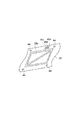
本発明に係る前記プレス機10に用いられる金型18は、図2に示すように、例えば上型18bの合わせ面24の型面部分24aを除く平坦面領域、すなわち被加工材28の非製品部分に対応する領域に、刻印部分40が形成されている。図2には、この刻印部分40が明確に示されるように、上型18bがその姿勢を上下に反転させた状態で示されている。
As shown in FIG. 2, the
図示の例では、上型18bの合わせ面24に設けられた4本のパイロットピン42(42a、42a、42b、42b)のうち、被加工材28の移送方向に沿って合わせ面24の一側に配列された一対のパイロットピン42a、42a間の平坦面部分に、刻印部分40が形成されている。上型18bのパイロットピン42は、プレス時、被加工材28の非製品部分を貫通して下型18aの対応するホール(図示せず)に受け入れられる。これにより、金型18と被加工材28との相対位置が確実に保持される。
In the illustrated example, of the four pilot pins 42 (42a, 42a, 42b, 42b) provided on the
図3ないし図5には、プレス時にパイロットピン42により被加工材28に形成された貫通穴44が示されている。この貫通穴44は、従来よく知られているように、被加工材28の材質に応じて、予め被加工材28に形成しておくことができる。
3 to 5 show a through
再び図2を参照するに、一対のパイロットピン42a、42a間に形成された刻印部分40は、図示の例では10個の突部40a〜40jから成る。各突部40a〜40jは、合わせ面24に平行な断面で見て、縦(x)×横(y)の各寸法が例えば約0.5mm×約0.2mmの同一の矩形平面形状を有する。また、各突部40a〜40jの突起高さ(h)はそれぞれ合わせ面24から所定の高さ寸法差を有するように、形成されている。図示の例では、例えば最も高い突部40aには、約20μmの高さ(h)が与えられ、以下、最も低い例えば約2μmの高さ(h)が与えられた突部40jに向けて順次約2μmずつ高さ寸法が減じられている。これら突部40a〜40jは、その横(y)方向を一対のパイロットピン42a、42aの整列方向に沿わせて、相互に例えば約0.2mmの所定の間隔(t)をおいて一列に配列されている。
Referring to FIG. 2 again, the engraved
この突部40a〜40jの個数およびそれぞれの高さ寸法は、例えば型面部分24aの高さ寸法dや金型18の設計時に設定されるダイハイト、すなわちボルスタ12の上面から設計上の下死点位置にあるスライド20の下面までの距離を基準にして、選択される。
The number of the protrusions 40a to 40j and the height dimensions of the protrusions 40a to 40j are, for example, the height d of the
例えば、スライド20の最適な下死点位置では、プレス機10の単一ストロークでの金型18によるプレス時に、最も高い高さの突部40aから順次低い高さを有する突部40eに至る全5個の突部40a〜40eによる押圧作用によって、被加工材28の上型18bに対向する面には、図3に示されているように対応する5つの凹所46a〜46eが形成されるように、刻印部分40の突部40a〜40jが設定されている。被加工材28に形成される凹所46a〜46eの深さ寸法は、対応する突部40a〜40eの高さ寸法にほぼ等しい。なお、下型18aには、被加工材28の材質などに応じて、適宜上型18bの突部40a〜40jに対応した凹部を設けることができるが、これに代えて突部40a〜40jに対応する下型18aの面部分を平坦面とすることができる。
For example, at the optimal bottom dead center position of the
本発明に係るプレス機10では、従来よく知られた下型18aおよび上型18bの共同の加工作用により、被加工材28には金型18の型面部分24aに対応した製品部分28a(図3ないし図5参照)が形成される。また、このプレス加工に伴い、前記したように、被加工材28の製品部分28aの外方、すなわち刻印部分40に対応する非製品部分には、突部40a〜40jから成る刻印部分40により、スライド20の下死点位置に応じた数の凹所46が形成される。
In the
刻印部分40について、前記したように、スライド20の最適な下死点位置で所定値である例えば5個の凹所46a〜46eが形成されるように刻印部分40が設定されている場合、所定値よりも少ない凹所46が形成されると、下死点位置が適正値より上方にずれたと判定することができる。図4に示される例では、適正値の一例である5個よりも少ない3つの凹所46a〜46cが形成された例が示されている。他方、所定値よりも多い凹所46が形成されると、下死点位置が適正値より下方にずれたと判定することができる。例えば図5に示す例では、突部40a〜40jに対応する全10個の凹所46a〜46jが形成された例を示す。しかも、予め各突部40a〜40jの高さ寸法差(t)を知ることにより、さらに、所定値からのずれがいかほどかを知ることができる。
As described above, when the marking
すなわち、図4に示す例では、所定数である5および観察される凹所46の数である3の差(2)と、各突部40a〜40jの高さの寸法差(2μm)との積(2×2μm)に等しい値分(4μm分)、下死点の適正値より上方(プラス方向)にずれていることを知ることができる。他方、図5に示す例では、所定数である5および観察される凹所46の数である10の差(−5)と、各突部40a〜40jの高さ寸法差(2μm)との積(2×−5μm)に等しい値分(10μm分)、下方(マイナス方向)にずれていることを知ることができる。 That is, in the example shown in FIG. 4, the difference between the predetermined number of 5 and the difference of 3 which is the number of the recesses 46 to be observed (2) and the dimensional difference (2 μm) between the heights of the protrusions 40a to 40j It can be seen that the value (4 μm) equal to the product (2 × 2 μm) is shifted upward (plus direction) from the appropriate value of the bottom dead center. On the other hand, in the example shown in FIG. 5, the difference between the predetermined number of 5 and the difference between the number of observed recesses 46 (−5) and the height dimension difference (2 μm) between the protrusions 40 a to 40 j. It can be seen that the value (10 μm) equal to the product (2 × −5 μm) is shifted downward (in the minus direction).
したがって、プレス機10を用いた本発明に係る方法によれば、前記したように金型18を経た被加工材28の非製品部分に形成される凹所46の個数を観察して、その個数を知ることにより、スライド20の下死点位置が最適に保持されているか否かを判定することができる。さらに、各突部40a〜40jの高さの寸法差についての情報を予め得ることにより、適正値からのずれの方向およびその量を知ることができる。そのため、例えばプレス機10の操作者が目視で凹所46の数を確認し、手動で前記調整機構のサーボモータ制御回路38を介してサーボモータ30の作動を制御することにより、比較的容易にスライド20の下死点位置のずれを修正することができる。
Therefore, according to the method of the present invention using the
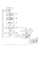
また、図1に示した制御装置32を用いることにより、スライド20の下死点位置のずれを自動的に修正することができる。以下、図6のフローチャートに沿ってプレス機10の作動を説明する。
Further, by using the
往復運動装置22の作動によって被加工材28へのプレス加工が開始されると、前記したように、金型18による製品部分28aの形成に伴って、被加工材28の非製品部分には、スライド20の下死点位置に応じて、刻印部分40により、その突部40a〜40jに対応した凹所46(46a〜46j)が形成される(ステップS1)。
When the press work to the
フィーダ26の間歇送り作用によって被加工材28の凹所46が金型18を通過すると、この間歇送り動作毎に、被加工材28の凹所46を含む領域が被加工材28の上面よりカメラ34aにより撮影される(ステップS2)。
When the recess 46 of the workpiece 28 passes through the
カメラ34aにより撮影された画像は、画像処理装置34での例えば2値化処理により凹所46の像を明確化された後、従来よく知られた画像切り取りのような従来よく知られた画像処理技術により、凹所46領域を判定され、該判定結果を含む画像情報が演算処理装置36に出力される(ステップS3)。
For an image taken by the
演算処理装置36には、スライド20の最適な下死点位置で形成される適正マーク数について情報(P0)が予め入力されている。演算処理装置36は、演算処理装置36から入力された前記判定結果から測定された凹所46すなわちマーク46の数(P)を求め、この測定マーク数(P)が適正マーク数(P0)に等しいか否かを判定する(ステップS4)。
Information (P 0 ) is input in advance to the
測定マーク数(P)が適正マーク数(P0)に等しいとき、例えば演算処理装置36が被加工材28の引き続く部分への同様な加工が必要か否かを判定する(ステップS5)。前記引き続く部分への加工が必要と判定された場合、再びステップS1に戻り、ステップS2〜S4を繰り返す。また、ステップS5で前記引き続く部分への同様な加工が不要と判定された場合、プレス機10のプレス加工が停止される。
When the number of measurement marks (P) is equal to the appropriate number of marks (P 0 ), for example, the
ステップS4で、測定マーク数(P)が適正マーク数(P0)に等しくないと判定されると、続いて演算処理装置36は、いずれが大きいかを判定すると共に、どれだけ大きいかを求める(ステップS6)。
If it is determined in step S4 that the number of measured marks (P) is not equal to the number of appropriate marks (P 0 ), the
ステップS6で測定マーク数(P)が適正マーク数(P0)より大きいと判定され、またその差が演算処理36により求められると、その差分に基づいて求められた修正信号がサーボモータ制御回路38に出力される。また、この修正信号を受けてサーボモータ制御回路38は、サーボモータ30を作動させてスライド20の下死点位置を適正値に向けて上方に修正する(ステップS7)。その後、最適な下死点位置での製品プレスのために、ステップS1に戻り、前記したと同様にステップS1〜ステップS4を繰り返す。
When it is determined in step S6 that the number of measured marks (P) is larger than the number of appropriate marks (P 0 ) and the difference is obtained by the
他方、ステップS6で測定マーク数(P)が適正マーク数(P0)より小さいと判定され、またその差が演算処理36により求められると、その差分に基づいて求められた修正信号がサーボモータ制御回路38に出力される。また、この修正信号を受けてサーボモータ制御回路38は、サーボモータ30を作動させてスライド20の下死点位置を適正値に向けて下方に修正する(ステップS8)。その後、最適な下死点位置での製品プレスのために、ステップS1に戻り、前記したと同様にステップS1〜ステップS4を繰り返す。
On the other hand, when it is determined in step S6 that the number of measured marks (P) is smaller than the number of appropriate marks (P 0 ) and the difference is obtained by the
このように、制御装置32を備えるプレス機10によれば、例えばSPM(ストローク数/分)や熱変動によってたとえスライド20の下死点位置にずれを生じても、そのずれを例えば数μmの単位で検出し、直ちにそのずれを自動的に修正することができるので、スライド20の下死点位置の大きなずれによる製品部分28aの精度低下を招くことなく、高精度でのプレス加工が可能となる。
As described above, according to the
しかも、下死点位置のずれの判定は従来のような製品の複雑な撮影画像からの情報に基づくことなく、前記マークの単純な画像情報に基づいてなされる。さらに、ずれの量は、前記マーク数に基づいて算出できる。このことから、従来に比較して画像処理の負荷が著しく軽減されるので、画像処理装置34および制御装置32を含むプレスシステムを従来に比較して迅速に作動させることができる。さらに、前記したように、画像処理の負荷が著しく軽減されることから、画像処理装置34および制御装置32の構成の単純化を図ることによって前記プレスシステムを従来に比較して安価に構成することができる。
In addition, the determination of the position of the bottom dead center position is made based on simple image information of the mark, not based on information from a complex captured image of a product as in the prior art. Further, the amount of deviation can be calculated based on the number of marks. As a result, the load of image processing is significantly reduced as compared with the prior art, so that the press system including the
前記したところでは、適正マーク数(P0)が金型18の設計時に設計ダイハイトに基づいて設定される例に沿って本願発明を説明したが、従来よく知られているように金型18を経た製品の撮影画像に基づいて適正マーク数(P0)を求めることができる。
As described above, the present invention has been described along the example in which the appropriate number of marks (P 0 ) is set based on the design die height when the
しかしながら、この場合、異なるマーク数(P0)を出現させるそれぞれの下死点位置で形成された製品毎に撮影画像を求め、それぞれの撮影画像から最適の製品精度を示す製品を選定し、当該製品が得られたときのマーク数(P0)を求める必要があるので、最適マーク数(P0)すなわち所定のマーク数(P0)を求めるための手順が煩雑化する。そのため、この所定のマーク数(P0)を簡単に決めるために、前記したように、金型18の設計時に所定のマーク数(P0)を決定することが望ましい。
However, in this case, a photographed image is obtained for each product formed at each bottom dead center position where a different number of marks (P 0 ) appears, and a product showing the optimum product accuracy is selected from each photographed image. Since it is necessary to obtain the number of marks (P 0 ) when the product is obtained, the procedure for obtaining the optimum number of marks (P 0 ), that is, the predetermined number of marks (P 0 ) becomes complicated. Therefore, in order to determine the predetermined number of marks (P 0) easily, as described above, it is desirable to determine the predetermined number of marks (P 0) in the design of the
本発明は、上記実施例に限定されず、その趣旨を逸脱しない限り、種々に変更することができる。例えば、刻印部分40を複数の突部で構成することに代えて、複数の凹部で構成することができる。この場合、前記複数の凹部は深さ寸法を互に異にして形成される。また、前記複数の凹部からなる刻印部分によって前記マークは被加工材の非製品領域に突起として形成されることから、該突起の数に基づいて、スライドの下死点位置のずれや程度が判定される。
The present invention is not limited to the above embodiments, and various modifications can be made without departing from the spirit of the present invention. For example, instead of configuring the marking
さらに、金型18の上型18bに刻印部分40を形成した例を示したが、上型18bに代えて下型18aに同様な刻印部分を形成することができる。
Furthermore, although the example which formed the marking
さらに、刻印部分40を複数の突部40a〜40jで構成する場合、各突部間のスペースすなわち間隔(t)を不要とし、前記したように、各突部40a〜40jを隣接して連続的に階段状に形成することができる。さらに、この階段状に隣接して形成された複数の突部により構成される階段状の段面に代えて、該段面を傾斜した連続平端面とすることができる。この場合、前記刻印部分によって被加工材に形成される単一凹所の長さ(複数の突部の連結方向すなわちy方向に沿った長さ)あるいは単一凹所の最深寸法を計測し、該計測値を基準値と比較することにより、スライドの下死点位置のずれを判定することができ、またそのずれを修正することができる。
Further, when the stamped
10 プレス機
12 ボルスタ
18 加工部(金型)
18a 下加工部(下金型)
18b 上加工部(上金型)
20 スライド
24 金型の合わせ面
28 被加工材
30、38 調整機構
34 画像処理装置
34a カメラ(撮影手段)
36 演算処理装置
40 刻印部分
40a〜40j 突部
46 マーク
46a〜46j 凹所
10
18a Lower machining part (lower mold)
18b Upper processing part (upper die)
20
36
Claims (15)
Priority Applications (1)
| Application Number | Priority Date | Filing Date | Title |
|---|---|---|---|
| JP2008324363A JP2010142852A (en) | 2008-12-19 | 2008-12-19 | Press machine, method for discriminating the bottom dead center position thereof and adjustment method therefor |
Applications Claiming Priority (1)
| Application Number | Priority Date | Filing Date | Title |
|---|---|---|---|
| JP2008324363A JP2010142852A (en) | 2008-12-19 | 2008-12-19 | Press machine, method for discriminating the bottom dead center position thereof and adjustment method therefor |
Publications (1)
| Publication Number | Publication Date |
|---|---|
| JP2010142852A true JP2010142852A (en) | 2010-07-01 |
Family
ID=42563824
Family Applications (1)
| Application Number | Title | Priority Date | Filing Date |
|---|---|---|---|
| JP2008324363A Pending JP2010142852A (en) | 2008-12-19 | 2008-12-19 | Press machine, method for discriminating the bottom dead center position thereof and adjustment method therefor |
Country Status (1)
| Country | Link |
|---|---|
| JP (1) | JP2010142852A (en) |
Cited By (1)
| Publication number | Priority date | Publication date | Assignee | Title |
|---|---|---|---|---|
| US9586375B2 (en) | 2013-07-03 | 2017-03-07 | Aida Engineering, Ltd. | Press machine controller |
-
2008
- 2008-12-19 JP JP2008324363A patent/JP2010142852A/en active Pending
Cited By (1)
| Publication number | Priority date | Publication date | Assignee | Title |
|---|---|---|---|---|
| US9586375B2 (en) | 2013-07-03 | 2017-03-07 | Aida Engineering, Ltd. | Press machine controller |
Similar Documents
| Publication | Publication Date | Title |
|---|---|---|
| EP1258298B1 (en) | Measuring device for a blank processing machine | |
| JP6585374B2 (en) | Press system and control method of press system | |
| JP3587208B1 (en) | Stereolithography processing reference correction method and stereolithography device | |
| KR101526935B1 (en) | A manufacturing device and method of the valve body | |
| CN108856445A (en) | Stamping device | |
| CN113365750A (en) | Method for manufacturing press-formed article and press line | |
| KR101932033B1 (en) | Method of Manufacturing Products Using Progressive Mold Without Cutting Bended Points at the Edge | |
| EP3153286B1 (en) | Processing workpieces with dies being level compensated with a compensation element | |
| JP2014512276A (en) | Method and apparatus for manufacturing flanged drawn member by simultaneous cutting | |
| KR20180018476A (en) | Method for performing precise laser cutting on a ribbon sheet and apparatus for carrying out the method | |
| JP2010142852A (en) | Press machine, method for discriminating the bottom dead center position thereof and adjustment method therefor | |
| JP6913476B2 (en) | Press brake and bending shape correction method | |
| US6832526B2 (en) | Bending method and single elongation value specifying device of bending apparatus | |
| US12214403B2 (en) | Method and device for determining a bending angle on a bending machine | |
| JP6889049B2 (en) | Press brake and bending method | |
| JP5785299B1 (en) | Inspection method for slippage of flat plate punching device | |
| JP2005211928A (en) | Press system | |
| JP2002178037A (en) | Sheet metal processing method and sheet metal processing system, blank processing apparatus used for the sheet metal processing system, work thickness measuring apparatus, springback measuring apparatus | |
| KR100788438B1 (en) | Laser processing method and device | |
| KR101305650B1 (en) | A metal flow control method in a press | |
| JP2017113798A (en) | Press machine | |
| JP2003191015A (en) | Step-bending method, bending device, and die for step- bending used for the device | |
| CN100558216C (en) | Connector stamping device and method | |
| US20250020448A1 (en) | Measuring device and forming machine | |
| JP4902343B2 (en) | Shaving method |