JP2010142836A - Plate bending device - Google Patents
Plate bending device Download PDFInfo
- Publication number
- JP2010142836A JP2010142836A JP2008321891A JP2008321891A JP2010142836A JP 2010142836 A JP2010142836 A JP 2010142836A JP 2008321891 A JP2008321891 A JP 2008321891A JP 2008321891 A JP2008321891 A JP 2008321891A JP 2010142836 A JP2010142836 A JP 2010142836A
- Authority
- JP
- Japan
- Prior art keywords
- pressing
- bending
- plate
- plate material
- punch
- Prior art date
- Legal status (The legal status is an assumption and is not a legal conclusion. Google has not performed a legal analysis and makes no representation as to the accuracy of the status listed.)
- Pending
Links
Images


Landscapes
- Bending Of Plates, Rods, And Pipes (AREA)
Abstract
Description
本発明は、板材の曲げ型面が形成されたダイスと、前記板材を前記曲げ型面に押し付ける押圧面が形成された押圧部材と、前記押圧面を前記曲げ型面に向けて押し付ける加圧機構とを備えている板曲げ装置に関する。 The present invention includes a die formed with a bending die surface of a plate material, a pressing member formed with a pressing surface that presses the plate material against the bending die surface, and a pressing mechanism that presses the pressing surface toward the bending die surface. The present invention relates to a plate bending apparatus.
上記板曲げ装置では、従来、曲げ型面が形成されたダイスに鋼鈑などの金属板材を載置し、その金属板材に曲げ型面と相似形状の押圧面が形成された押圧部材としてのポンチを一方向から押し付けることにより、板材を曲げ加工できるように構成してある(例えば、特許文献1参照。)。 In the above plate bending apparatus, conventionally, a punch as a pressing member in which a metal plate material such as a steel plate is placed on a die formed with a bending die surface, and a pressing surface similar in shape to the bending die surface is formed on the metal plate material. Is pressed from one direction so that the plate material can be bent (see, for example, Patent Document 1).
上記従来の板曲げ装置では、ダイスに載置した板材にポンチを一方向から押し付けながら曲げるために、押し付け途中において、板材がダイスやポンチに対して滑り、その結果、曲げ加工後の板材にダイスやポンチなどによる擦り痕が生じ易く、曲げ加工後の板材の外観品質が低下し易い欠点がある。
さらに、板材の内部に発生した弾性歪みが回復する現象(スプリングバック)により、所望の曲げ形状を得難い欠点がある。
本発明は上記実情に鑑みてなされたものであって、曲げ加工後の板材に擦り痕が生じ難く、所望の曲げ形状を得ることができる板曲げ装置を提供することを目的とする。
In the conventional plate bending apparatus described above, the punch is bent from one direction against the plate placed on the die, so that the plate slides against the die or the punch during the pressing, and as a result, the plate is bent into the plate after bending. There is a drawback that scratch marks are easily generated by a punch or a punch, and the appearance quality of the plate material after bending is easily deteriorated.
Furthermore, there is a drawback that it is difficult to obtain a desired bent shape due to a phenomenon (spring back) in which elastic strain generated in the plate material is recovered.
The present invention has been made in view of the above circumstances, and an object of the present invention is to provide a plate bending apparatus in which a scratch mark is hardly generated on a plate material after bending and a desired bending shape can be obtained.
本発明の第1特徴構成は、板材の曲げ型面が形成されたダイスと、前記板材を前記曲げ型面に押し付ける押圧面が形成された押圧部材と、前記押圧面を前記曲げ型面に向けて押し付ける加圧機構と、前記押圧面の押し付けに際して、前記押圧部材の移動方向を、前記押圧面が前記板材に対する押圧箇所を支点にして前記曲げ型面に向けて傾動するように案内するガイド機構とを備えている点にある。 A first characteristic configuration of the present invention includes a die formed with a bending die surface of a plate material, a pressing member formed with a pressing surface that presses the plate material against the bending die surface, and the pressing surface facing the bending die surface. A pressing mechanism that presses the pressing surface, and a guide mechanism that guides the moving direction of the pressing member so that the pressing surface tilts toward the bending mold surface with a pressing position against the plate material as a fulcrum when pressing the pressing surface. It is in the point equipped with.
〔作用及び効果〕
本構成の板曲げ装置であれば、押圧面の曲げ型面に向けた押し付けに際して、押圧部材の移動方向が、押圧面が板材に対する押圧箇所を支点にして曲げ型面に向けて傾動するように案内される。
したがって、板材をダイスや押圧部材に対して滑らせることなく、板材を曲げ型面になぞらせながら曲げることができるので、曲げ加工後の板材に擦り痕が生じ難い。
[Action and effect]
In the case of the plate bending apparatus of this configuration, when the pressing surface is pressed toward the bending die surface, the moving direction of the pressing member is tilted toward the bending die surface with the pressing surface serving as a fulcrum for the pressing portion against the plate material. Guided.
Therefore, it is possible to bend the plate material while tracing the plate material on the bending mold surface without sliding the plate material against the die or the pressing member.
本発明の第2特徴構成は、前記曲げ型面が円弧面であると共に、前記押圧面が平面であり、前記ガイド機構が、前記押圧面の前記板材に対する押圧箇所の軌跡が、前記円弧面の中心軸芯に沿う方向視において、前記円弧面に沿って曲げられた前記板材部分に対するインボリュート曲線となるように構成してある点にある。 According to a second characteristic configuration of the present invention, the bending die surface is an arc surface, the pressing surface is a flat surface, and the guide mechanism has a locus of a pressing portion of the pressing surface with respect to the plate material, When viewed in a direction along the central axis, the involute curve is formed with respect to the plate portion bent along the arc surface.
〔作用及び効果〕
本構成であれば、押圧面の板材に対する押圧箇所の軌跡が、円弧面の中心軸芯に沿う方向視において、円弧面に沿って曲げられた板材部分に対するインボリュート曲線となるように、押圧部材の移動方向が案内される。
したがって、押圧部材を所望の押圧ストロークで移動させながら、押圧面を板材に対する押圧箇所を支点にして曲げ型面に向けて傾動させて、板材を曲げ型面に精度良くなぞらせながら曲げることができる。
また、押圧ストロークを調整することにより、板材の内部に発生した弾性歪みが回復する現象(スプリングバック)を考慮した曲げ加工を実施し易い。
[Action and effect]
With this configuration, the locus of the pressing member with respect to the plate member of the pressing surface is an involute curve with respect to the plate member portion bent along the arc surface in a direction view along the center axis of the arc surface. The direction of movement is guided.
Therefore, while moving the pressing member with a desired pressing stroke, the pressing surface can be tilted toward the bending die surface with the pressing portion against the plate material as a fulcrum, and the plate material can be bent while accurately tracing the bending die surface. it can.
Further, by adjusting the pressing stroke, it is easy to perform a bending process in consideration of a phenomenon (spring back) in which the elastic strain generated inside the plate material is recovered.
本発明の第3特徴構成は、前記ガイド機構は、前記押圧部材に設けたガイドローラと、前記ガイドローラを案内するガイド溝とを備えている点にある。 According to a third characteristic configuration of the present invention, the guide mechanism includes a guide roller provided in the pressing member and a guide groove for guiding the guide roller.
〔作用及び効果〕
本構成であれば、押圧部材の姿勢変化が極めて滑らかとなり、かつ、繰り返し精度良く案内することができる。
[Action and effect]
If it is this structure, the attitude | position change of a press member will become very smooth, and it can guide with sufficient repeatability.
以下に本発明の実施の形態を図面に基づいて説明する。
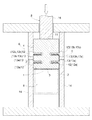
図1,図2は、本発明による鋼板(板材の一例)Aの板曲げ装置を示す。
板曲げ装置は、鋼板Aの曲げ型面1が形成されたダイス2と、鋼板Aを曲げ型面1に押し付ける押圧面3が形成されたポンチ(押圧部材の一例)4と、ポンチ4を押し下げて押圧面3を曲げ型面1に向けて押し付ける加圧機構5と、押圧面3の曲げ型面1に向けた押し付けに際して、ポンチ4の移動方向を案内するガイド機構6とを備えている。
Embodiments of the present invention will be described below with reference to the drawings.
1 and 2 show a plate bending apparatus for a steel plate (an example of a plate material) A according to the present invention.
The plate bending apparatus includes a
ダイス2は、鋼板Aを載置する水平方向に沿う扁平な載置面7と、その載置面7に対して交差する方向に沿う扁平な側面8と、載置面7と側面8とが交差する角部(出隅部)に形成した曲げ型面1とを備えている。
The die 2 includes a
曲げ型面1は、半径が数mm程度の円弧面で構成してあり、載置面7及び側面8の夫々は曲げ型面(円弧面)1に対して接線方向から連続している。
The
ダイス2の上方には、載置面7に載置した鋼板Aを動かないように把持するために、水平方向に沿う扁平な矩形のクランプ面9を備えた厚肉のクランプ板10を図示しない装置フレームなどに固定してある。
A
ダイス2は、載置面7をクランプ面9と平行に保持して、クランプ面9に対する遠近方向に、図示しない油圧装置などで昇降操作自在に設けてある。
The
ポンチ4は、加圧機構5で下向きに加圧される被加圧面11と、押圧面3とを上下に備え、被加圧面11は加工が容易な円弧面に形成してあり、押圧面3は扁平な矩形平面に形成してある。
The
クランプ板10は、図3に示すように、クランプ面9の、曲げ型面1の側の端縁P1が、鋼板Aを載置面7とクランプ面9との間に挟み込んでいる状態で、曲げ型面1の曲り開始位置P2よりも僅か(本実施形態では0.5〜1.0mm程度)に載置面7の側に入り込む位置となるように固定してある。
As shown in FIG. 3, the
ガイド機構6は、ポンチ4の左右側面の夫々に設けてある三つのガイドローラ12(12a,12b,12c)と、これらのガイドローラ12を各別に案内する三つのガイド溝13(13a,13b,13c)を形成した左右のガイドブロック14とを備えている。
ガイドブロック14は、ポンチ4の左右両側に位置させて、図示しない装置基台などに固定してある。
The
The
ポンチ4と図示しない装置フレームなどとに亘って引張スプリング15を装着してあり、曲げ動作を行わない待機位置で待機しているポンチ4は、引張スプリング15の付勢力により、図1に示すように、各ガイドローラ12がガイド溝13の上側終端部に接当して、押圧面3がクランプ面9と面一になる姿勢に保持されている。
A
加圧機構5は、油圧装置などで昇降操作自在なパンチ16を備えた汎用プレス機で構成してある。
パンチ16はポンチ4と略同じ横幅を備えている。パンチ16を下降させることにより、被加圧面11が下向きに押圧されて、ポンチ4が引張スプリング15の付勢力に抗してガイド溝13に沿って回動しながら押し下げられ、ポンチ4の押圧面3が、鋼板Aを挟んで、曲げ型面1に向けて押し付けられる。
The pressurizing
The
ポンチ4が押し下げられる際には、三つのガイドローラ12のうちの、曲げ型面1に近い側のガイドローラ12aは、ガイド溝13aの曲げ型面1に近い側のガイド面19aに押し付けられながら転動し、残りのガイドローラ12b,12cは、ガイド溝13b,13cの曲げ型面1から遠い側のガイド面19b,cに押し付けられながら転動する。
When the
よって、ポンチ4は、ガイドブロック14の夫々に対して三つのガイドローラ12によって回動径方向に突っ張る状態で回動するので、その回動姿勢が安定する。
尚、ガイド溝13の数は、可能であれば、四つ以上でも良い。
Therefore, since the
The number of
ポンチ4がガイド溝13に沿って押し下げられるに伴って、ポンチ4とパンチ16とが互いに干渉しないように、パンチ16の下部を入り込みを許容する溝17をポンチ4に形成してある。
A
尚、パンチ16の被加圧面11に対する押圧部を、例えばポンチ4の横幅と略同じ長さの押圧ローラで構成して、この押圧ローラを、パンチ16の下部にガイドローラ12の回転軸芯と平行な軸芯周りで遊転自在に支持してあってもよい。
The pressing portion of the
三つのガイド溝13は、図3に示すように、ポンチ4の押し下げに伴う押圧面3の鋼板Aに対する押圧箇所Q1,Q2,Q3………の移動軌跡が、曲げ型面である円弧面1の中心軸芯Xに沿う方向において、曲げ型面(円弧面)1に沿って曲げられた板材部分18に対するインボリュート曲線R1,R2,R3………となるように形成してある。
As shown in FIG. 3, the three
したがって、ポンチ4の押し下げに伴って、押圧面3が鋼板Aに対する押圧箇所Q1,Q2,Q3………を支点にして曲げ型面1に向けて傾動するように、ポンチ4の移動方向が案内される。
Therefore, as the
上記板曲げ装置による鋼板Aの曲げ動作を説明する。
図4に示すように、ポンチ4を待機位置に位置させておくと共に、ダイス2を下降させて、鋼板Aを載置面7に載置する。
The bending operation of the steel plate A by the plate bending apparatus will be described.
As shown in FIG. 4, the
次に、ダイス2を上昇させることにより、図5に示すように、鋼板Aを載置面7とクランプ面9との間に挟み込んで、動かないように把持する。
この状態では、ポンチ4の押圧面3のクランプ板10の側の端縁P3は、クランプ面9の曲げ型面1の側の端縁P1と、曲げ型面1の曲り開始位置P2との中間に位置している。
Next, by raising the
In this state, the edge P3 on the
次に、パンチ16を下降させて被加圧面11を押圧することにより、図6に示すように、所定の押圧ストローク(本実施形態では、鋼板Aがダイス2の側面8とポンチ4の押圧面3との間に挟み込まれるまでのストローク)で、ポンチ4を引張スプリング15の付勢力に抗してガイド溝13に沿って押し下げる。
Next, by lowering the
このポンチ4を押し下げる動作に伴って、鋼板Aをダイス2やポンチ4に対して滑らせることなく、鋼板Aを曲げ型面(円弧面)1になぞらせながら曲げることができる
Along with the operation of pushing down the
次に、パンチ16を上昇させると、ポンチ4が引張スプリング15の付勢力でガイド溝13に沿って引き上げられて待機位置に移動し、図7に示すように、ダイス2を下降させて、曲げ加工された後の鋼板Aを取り出す。
Next, when the
〔その他の実施形態〕
1.本発明による板曲げ装置は、断面形状が楕円形の一部となる曲げ型面や断面形状が多角形の一部となる曲げ型面がダイスに形成されていてもよい。
2.本発明による板曲げ装置は、二つの平面が直角或いは鈍角で交差する角部 (出隅部)に曲げ型面を形成してあるダイスを備えていてもよい。
3.本発明による板曲げ装置は、湾曲面からなる押圧面が押圧部材に形成されていてもよい。
4.本発明による板曲げ装置は、鋼板以外の各種金属製の板材を曲げるためのものであってもよい。
[Other Embodiments]
1. In the plate bending apparatus according to the present invention, a bending die surface whose cross-sectional shape becomes a part of an ellipse and a bending die surface whose cross-sectional shape becomes a part of a polygon may be formed on the die.
2. The plate bending apparatus according to the present invention may include a die in which a bending die surface is formed at a corner (protruding corner) where two planes intersect at a right angle or an obtuse angle.
3. In the plate bending apparatus according to the present invention, a pressing surface made of a curved surface may be formed on the pressing member.
4). The plate bending apparatus according to the present invention may be for bending various metal plate materials other than steel plates.
1 曲げ型面
2 ダイス
3 押圧面
4 押圧部材
5 加圧機構
6 ガイド機構
12 ガイドローラ
13 ガイド溝
18 板材部分
A 板材
Q1,Q2,Q3 押圧箇所
R1,R2,R3 インボリュート曲線
X 中心軸芯
DESCRIPTION OF
Claims (3)
前記板材を前記曲げ型面に押し付ける押圧面が形成された押圧部材と、
前記押圧面を前記曲げ型面に向けて押し付ける加圧機構と、
前記押圧面の押し付けに際して、前記押圧部材の移動方向を、前記押圧面が前記板材に対する押圧箇所を支点にして前記曲げ型面に向けて傾動するように案内するガイド機構とを備えている板曲げ装置。 A die on which a bending die surface of the plate material is formed;
A pressing member formed with a pressing surface for pressing the plate material against the bending mold surface;
A pressure mechanism for pressing the pressing surface toward the bending mold surface;
A plate bending provided with a guide mechanism that guides the moving direction of the pressing member when the pressing surface is pressed so that the pressing surface tilts toward the bending mold surface with a pressing portion against the plate material as a fulcrum. apparatus.
前記ガイド機構が、前記押圧面の前記板材に対する押圧箇所の軌跡が、前記円弧面の中心軸芯に沿う方向視において、前記円弧面に沿って曲げられた前記板材部分に対するインボリュート曲線となるように構成してある請求項1記載の板曲げ装置。 The bending mold surface is an arc surface, and the pressing surface is a plane,
The guide mechanism is such that the locus of the pressing portion of the pressing surface with respect to the plate material becomes an involute curve with respect to the plate material portion bent along the arc surface in a direction view along the central axis of the arc surface. The plate bending apparatus according to claim 1, which is configured.
Priority Applications (1)
| Application Number | Priority Date | Filing Date | Title |
|---|---|---|---|
| JP2008321891A JP2010142836A (en) | 2008-12-18 | 2008-12-18 | Plate bending device |
Applications Claiming Priority (1)
| Application Number | Priority Date | Filing Date | Title |
|---|---|---|---|
| JP2008321891A JP2010142836A (en) | 2008-12-18 | 2008-12-18 | Plate bending device |
Publications (1)
| Publication Number | Publication Date |
|---|---|
| JP2010142836A true JP2010142836A (en) | 2010-07-01 |
Family
ID=42563810
Family Applications (1)
| Application Number | Title | Priority Date | Filing Date |
|---|---|---|---|
| JP2008321891A Pending JP2010142836A (en) | 2008-12-18 | 2008-12-18 | Plate bending device |
Country Status (1)
| Country | Link |
|---|---|
| JP (1) | JP2010142836A (en) |
Cited By (1)
| Publication number | Priority date | Publication date | Assignee | Title |
|---|---|---|---|---|
| CN115415419A (en) * | 2022-09-22 | 2022-12-02 | 苏红军 | Efficient metal plate stamping process |
-
2008
- 2008-12-18 JP JP2008321891A patent/JP2010142836A/en active Pending
Cited By (1)
| Publication number | Priority date | Publication date | Assignee | Title |
|---|---|---|---|---|
| CN115415419A (en) * | 2022-09-22 | 2022-12-02 | 苏红军 | Efficient metal plate stamping process |
Similar Documents
| Publication | Publication Date | Title |
|---|---|---|
| CN110814100B (en) | Plate bending forming device | |
| JP6618669B2 (en) | Bending machine | |
| KR101545086B1 (en) | Press mold for bending machine | |
| TW200817133A (en) | Machining apparatus of sides of plate | |
| JP2011036916A (en) | Variable linear geometry machine for continuously forming square tube | |
| KR20090122671A (en) | Width-variable guidance apparatus for a steel plate cutter | |
| KR20140111160A (en) | Press die | |
| JP5835328B2 (en) | Electric heating apparatus and method | |
| JP2010142836A (en) | Plate bending device | |
| KR101845727B1 (en) | Roller banding device | |
| JP4164618B2 (en) | Bending test equipment | |
| US20180264532A1 (en) | Step-bending die device | |
| JP2008012572A (en) | Roller hemming device | |
| CN105522064A (en) | Locating device for bending machine and bending machine with same | |
| JP2013146750A (en) | Plate material bending method and plate material bending machine | |
| JP6106481B2 (en) | Cold roll forming machine and cold roll forming method | |
| JPH10216835A (en) | Steel plate camber simple straightening device | |
| JP2003220528A (en) | Clamping device for moving body | |
| JP6403288B2 (en) | Butt joining device for strip metal sheet | |
| JP3587288B2 (en) | Cutter lifting mechanism for equipment with cutting function | |
| JP7050984B2 (en) | Method of reducing residual stress at the edge of the work | |
| CN215315234U (en) | Auxiliary supporting device for mechanical stamping forming | |
| JP2003181543A (en) | Bending device for material | |
| JP2000317529A (en) | Rotary type bending machine | |
| JP7145132B2 (en) | Tapered tube press bending device |