JP2010142801A - 空気分離モジュールに所定の温度の空気を供給する装置および方法 - Google Patents
空気分離モジュールに所定の温度の空気を供給する装置および方法 Download PDFInfo
- Publication number
- JP2010142801A JP2010142801A JP2009264487A JP2009264487A JP2010142801A JP 2010142801 A JP2010142801 A JP 2010142801A JP 2009264487 A JP2009264487 A JP 2009264487A JP 2009264487 A JP2009264487 A JP 2009264487A JP 2010142801 A JP2010142801 A JP 2010142801A
- Authority
- JP
- Japan
- Prior art keywords
- air
- path
- separation module
- heat exchanger
- temperature
- Prior art date
- Legal status (The legal status is an assumption and is not a legal conclusion. Google has not performed a legal analysis and makes no representation as to the accuracy of the status listed.)
- Pending
Links
- 238000000926 separation method Methods 0.000 title claims abstract description 63
- 238000000034 method Methods 0.000 title claims description 9
- 238000011144 upstream manufacturing Methods 0.000 claims description 3
- 239000000203 mixture Substances 0.000 abstract description 6
- 230000001105 regulatory effect Effects 0.000 abstract description 3
- 239000003570 air Substances 0.000 description 155
- 238000001816 cooling Methods 0.000 description 13
- 239000001301 oxygen Substances 0.000 description 9
- 229910052760 oxygen Inorganic materials 0.000 description 9
- QVGXLLKOCUKJST-UHFFFAOYSA-N atomic oxygen Chemical compound [O] QVGXLLKOCUKJST-UHFFFAOYSA-N 0.000 description 8
- IJGRMHOSHXDMSA-UHFFFAOYSA-N Atomic nitrogen Chemical compound N#N IJGRMHOSHXDMSA-UHFFFAOYSA-N 0.000 description 5
- 239000002828 fuel tank Substances 0.000 description 4
- 229910052757 nitrogen Inorganic materials 0.000 description 3
- 239000012080 ambient air Substances 0.000 description 2
- 230000001276 controlling effect Effects 0.000 description 2
- 239000000835 fiber Substances 0.000 description 2
- 239000007789 gas Substances 0.000 description 2
- 238000002485 combustion reaction Methods 0.000 description 1
- 230000006835 compression Effects 0.000 description 1
- 238000007906 compression Methods 0.000 description 1
- 238000009792 diffusion process Methods 0.000 description 1
- 230000000694 effects Effects 0.000 description 1
- 239000000446 fuel Substances 0.000 description 1
- 230000017525 heat dissipation Effects 0.000 description 1
- 239000012510 hollow fiber Substances 0.000 description 1
- 239000011261 inert gas Substances 0.000 description 1
- 239000012528 membrane Substances 0.000 description 1
- 238000012986 modification Methods 0.000 description 1
- 230000004048 modification Effects 0.000 description 1
- QJGQUHMNIGDVPM-UHFFFAOYSA-N nitrogen group Chemical group [N] QJGQUHMNIGDVPM-UHFFFAOYSA-N 0.000 description 1
- 150000002926 oxygen Chemical class 0.000 description 1
Images

Classifications
-
- B—PERFORMING OPERATIONS; TRANSPORTING
- B64—AIRCRAFT; AVIATION; COSMONAUTICS
- B64D—EQUIPMENT FOR FITTING IN OR TO AIRCRAFT; FLIGHT SUITS; PARACHUTES; ARRANGEMENT OR MOUNTING OF POWER PLANTS OR PROPULSION TRANSMISSIONS IN AIRCRAFT
- B64D37/00—Arrangements in connection with fuel supply for power plant
- B64D37/32—Safety measures not otherwise provided for, e.g. preventing explosive conditions
Landscapes
- Engineering & Computer Science (AREA)
- Aviation & Aerospace Engineering (AREA)
- Heat-Exchange Devices With Radiators And Conduit Assemblies (AREA)
- Feeding, Discharge, Calcimining, Fusing, And Gas-Generation Devices (AREA)
- Control Of Temperature (AREA)
Abstract
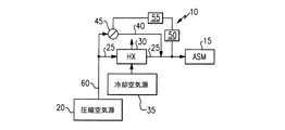
【解決手段】圧縮空気源220が、ダクト260と、圧縮空気を空気分離モジュール215まで直接的に送る第1の経路240と、を介して、高温の圧縮空気を通流させるとともに、熱交換器230内を通る第2の経路225を介して高温の圧縮空気を通流させる。熱交換器230内を通る第2の経路225は、熱交換器230の下流に配置されている弁245によって調節される。センサ250が、空気分離モジュール215に流入するときの空気の温度を測定し、コントローラ255が、センサ250からのフィードバックを受けるとともに、第1の経路と第2の経路からの温度の異なる空気の混合物が適当な温度となって空気分離モジュールに供給されるように、弁245の位置を制御する。
【選択図】図2
Description
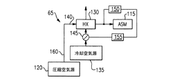
220…圧縮空気源
230…熱交換器
235…冷却空気源
255…コントローラ
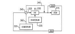
315…空気分離モジュール
320…圧縮空気源
330…熱交換器
235…冷却空気源
230…熱交換器
255…冷却空気源
Claims (10)
- 空気分離モジュールに所定の温度の空気を供給する装置であって、
ある温度の空気を上記空気分離モジュールに送る第1の経路と、
ある温度の空気を上記空気分離モジュールに送る第2の経路と、
上記第2の経路が内部を通り、かつその空気の温度を第2の温度になるように調節する熱交換器と、
上記第2の経路を通して流れる空気の量を制御する弁と、
を備え、
上記弁による制御によって、上記第1の経路と第2の経路を介して上記空気分離モジュールに送られる空気の温度が上記空気分離モジュールを作動させるための所望の温度よりも低い場合、ほぼすべての空気が上記第1の経路を通して流れるようにすることを特徴とする装置。 - 上記第1の経路と第2の経路が上記熱交換器の下流で合流することを特徴とする請求項1に記載の装置。
- 上記第1の経路および第2の経路に、ある温度の圧縮空気を供給する圧縮空気源をさらに備えることを特徴とする請求項1に記載の装置。
- 上記弁は、上記熱交換器の上流に配置されていることを特徴とする請求項1に記載の装置。
- 上記弁は、上記熱交換器の下流に配置されていることを特徴とする請求項1に記載の装置。
- 所望の温度範囲で作動し、かつ該所望の温度範囲よりも低い環境下で用いられる空気分離モジュールに、所定の温度の空気を供給する方法であって、
上記空気分離モジュールに第1の空気流を供給し、
選択的に熱交換器に第2の空気流を供給し、
上記第1の空気流と第2の空気流とを混合することによって上記所望の温度範囲で空気を送ることができる場合には、上記第1の空気流と第2の空気流とを混合すること、
を含む方法。 - 上記混合された空気流を上記分離モジュールに供給することをさらに含む請求項6に記載の方法。
- 上記混合することによって上記所望の温度範囲で空気を送ることができない場合には、上記第1の空気流と第2の空気流とを混合しないことをさらに含む請求項6に記載の方法。
- 選択的に第2の空気流を供給することが、上記熱交換器の上流での弁の調整を含む請求項6に記載の方法。
- 選択的に第2の空気流を供給することが、上記熱交換器の下流での弁の調整を含む請求項6に記載の方法。
Applications Claiming Priority (1)
| Application Number | Priority Date | Filing Date | Title |
|---|---|---|---|
| US20308108P | 2008-12-18 | 2008-12-18 |
Publications (1)
| Publication Number | Publication Date |
|---|---|
| JP2010142801A true JP2010142801A (ja) | 2010-07-01 |
Family
ID=41694614
Family Applications (1)
| Application Number | Title | Priority Date | Filing Date |
|---|---|---|---|
| JP2009264487A Pending JP2010142801A (ja) | 2008-12-18 | 2009-11-20 | 空気分離モジュールに所定の温度の空気を供給する装置および方法 |
Country Status (3)
| Country | Link |
|---|---|
| US (1) | US20100155046A1 (ja) |
| EP (1) | EP2202150A3 (ja) |
| JP (1) | JP2010142801A (ja) |
Cited By (2)
| Publication number | Priority date | Publication date | Assignee | Title |
|---|---|---|---|---|
| JP2015113113A (ja) * | 2013-12-06 | 2015-06-22 | イートン リミテッドEaton Limited | 機上不活性気体生成システムおよび機上不活性気体生成方法 |
| US9718023B2 (en) | 2010-11-04 | 2017-08-01 | Ube Industries, Ltd. | Gas separation membrane module and gas separation method |
Families Citing this family (10)
| Publication number | Priority date | Publication date | Assignee | Title |
|---|---|---|---|---|
| JP5191792B2 (ja) * | 2008-05-07 | 2013-05-08 | ヤンマー株式会社 | 定置式エンジンの冷却水回路 |
| CN102527241B (zh) * | 2010-11-04 | 2015-11-04 | 宇部兴产株式会社 | 气体分离膜组件及气体分离方法 |
| US8612063B2 (en) * | 2011-05-02 | 2013-12-17 | Honeywell International, Inc. | Temperature control setpoint offset for ram air minimization |
| US20140345700A1 (en) * | 2013-05-22 | 2014-11-27 | Hamilton Sundstrand Corporation | Pressure monitoring system for a fuel tank and method |
| US9694314B2 (en) | 2014-10-15 | 2017-07-04 | Parker-Hannifin Corporation | OBIGGS ASM performance modulation via temperature control |
| CN104460790B (zh) * | 2014-12-30 | 2016-09-28 | 北京航空航天大学 | 一种动态航空热动力试验系统和温度、压力快速控制方法 |
| US10137406B2 (en) | 2015-06-11 | 2018-11-27 | Hamilton Sundstrand Corporation | Temperature controlled nitrogen generation system |
| US20170313435A1 (en) * | 2016-04-29 | 2017-11-02 | Hamilton Sundstrand Corporation | Fuel tank inerting systems for aircraft |
| US10919637B2 (en) * | 2016-07-12 | 2021-02-16 | Hamilton Sunstrand Corporation | Temperature control system for fuel tank inerting system |
| CN106647855A (zh) * | 2016-11-03 | 2017-05-10 | 北京航天试验技术研究所 | 一种低温流体温度调节装置 |
Citations (4)
| Publication number | Priority date | Publication date | Assignee | Title |
|---|---|---|---|---|
| JP2000142592A (ja) * | 1998-11-06 | 2000-05-23 | Shimadzu Corp | 航空機の防爆装置 |
| JP2000257969A (ja) * | 1999-03-11 | 2000-09-22 | Sanyo Electric Co Ltd | 低温空気供給装置 |
| JP2004197737A (ja) * | 2002-12-17 | 2004-07-15 | Hamilton Sundstrand Corp | 低動力窒素富化空気生成システム |
| JP2008509841A (ja) * | 2004-08-16 | 2008-04-03 | エアバス・ドイチュラント・ゲーエムベーハー | 航空機への空気供給 |
Family Cites Families (12)
| Publication number | Priority date | Publication date | Assignee | Title |
|---|---|---|---|---|
| FI83808C (fi) * | 1988-10-05 | 1991-08-26 | Tampella Oy Ab | Foerfarande foer styrning av luftproduktionen i en skruvkompressor. |
| US4979362A (en) * | 1989-05-17 | 1990-12-25 | Sundstrand Corporation | Aircraft engine starting and emergency power generating system |
| US6739359B2 (en) * | 2002-10-04 | 2004-05-25 | Shaw Aero Devices, Inc. | On-board inert gas generating system optimization by pressure scheduling |
| US7048231B2 (en) * | 2002-10-04 | 2006-05-23 | Shaw Aero Devices, Inc. | Increasing the performance of aircraft on-board inert gas generating systems by turbocharging |
| US6926490B2 (en) * | 2003-01-21 | 2005-08-09 | Hamilton Sundstrand | Self-actuated bearing cooling flow shut-off valve |
| WO2004099579A2 (en) * | 2003-03-07 | 2004-11-18 | Shaw Aero Devices, Inc. | Cooling system for an on-board inert gas generating system |
| US7374601B2 (en) * | 2003-09-22 | 2008-05-20 | Parker-Hannifin Corporation | Air separation system and method with modulated warning flow |
| US7081153B2 (en) * | 2003-12-02 | 2006-07-25 | Honeywell International Inc. | Gas generating system and method for inerting aircraft fuel tanks |
| US7172156B1 (en) * | 2004-03-16 | 2007-02-06 | Shaw Aero Devices, Inc. | Increasing the performance of aircraft on-board inert gas generating systems by turbocharging |
| US7204868B2 (en) * | 2004-03-30 | 2007-04-17 | The Boeing Company | Method and apparatus for generating an inert gas on a vehicle |
| US7509968B2 (en) * | 2004-07-28 | 2009-03-31 | Hamilton Sundstrand Corporation | Flow control for on-board inert gas generation system |
| US7625434B2 (en) * | 2006-09-12 | 2009-12-01 | Honeywell International Inc. | Enhanced OBIGGS |
-
2009
- 2009-09-22 US US12/564,281 patent/US20100155046A1/en not_active Abandoned
- 2009-11-20 JP JP2009264487A patent/JP2010142801A/ja active Pending
- 2009-12-18 EP EP09252827.2A patent/EP2202150A3/en not_active Withdrawn
Patent Citations (4)
| Publication number | Priority date | Publication date | Assignee | Title |
|---|---|---|---|---|
| JP2000142592A (ja) * | 1998-11-06 | 2000-05-23 | Shimadzu Corp | 航空機の防爆装置 |
| JP2000257969A (ja) * | 1999-03-11 | 2000-09-22 | Sanyo Electric Co Ltd | 低温空気供給装置 |
| JP2004197737A (ja) * | 2002-12-17 | 2004-07-15 | Hamilton Sundstrand Corp | 低動力窒素富化空気生成システム |
| JP2008509841A (ja) * | 2004-08-16 | 2008-04-03 | エアバス・ドイチュラント・ゲーエムベーハー | 航空機への空気供給 |
Cited By (4)
| Publication number | Priority date | Publication date | Assignee | Title |
|---|---|---|---|---|
| US9718023B2 (en) | 2010-11-04 | 2017-08-01 | Ube Industries, Ltd. | Gas separation membrane module and gas separation method |
| US10369515B2 (en) | 2010-11-04 | 2019-08-06 | Ube Industries, Ltd. | Gas separation membrane module and method for gas separation |
| US10765992B2 (en) | 2010-11-04 | 2020-09-08 | Ube Industries, Ltd. | Gas separation membrane module and method for gas separation |
| JP2015113113A (ja) * | 2013-12-06 | 2015-06-22 | イートン リミテッドEaton Limited | 機上不活性気体生成システムおよび機上不活性気体生成方法 |
Also Published As
| Publication number | Publication date |
|---|---|
| US20100155046A1 (en) | 2010-06-24 |
| EP2202150A2 (en) | 2010-06-30 |
| EP2202150A3 (en) | 2013-07-24 |
Similar Documents
| Publication | Publication Date | Title |
|---|---|---|
| JP2010142801A (ja) | 空気分離モジュールに所定の温度の空気を供給する装置および方法 | |
| US7374601B2 (en) | Air separation system and method with modulated warning flow | |
| US7608131B2 (en) | Three flow architecture and method for aircraft OBIGGS | |
| US11117094B2 (en) | Temperature controlled nitrogen generation system | |
| US9102416B1 (en) | Inert gas generating system | |
| CN101384484B (zh) | 用于改善飞行器压力舱中的空气质量的系统 | |
| CN101010238B (zh) | 飞行器的空气供应 | |
| US9901874B2 (en) | High temperature air separation system architecture | |
| US11780601B2 (en) | Temperature control system for fuel tank inerting system | |
| US20190283897A1 (en) | Cooled air source for a catalytic inerting condenser | |
| US20160177878A1 (en) | Method and system for a gas turbine engine air ventilation purge circuit | |
| FR2855812A1 (fr) | Systeme embarque de generation et de fourniture d'oxygene et d'azote | |
| CN101005987A (zh) | 飞行器中的空气冷却 | |
| US11891188B2 (en) | Fuel tank inerting system and method | |
| CN105409043A (zh) | 具有一个冷却剂回路的燃料电池系统 | |
| EP3543132A1 (en) | Cooled air source for catalytic inerting | |
| US9272790B2 (en) | Nitrogen enriched air supply system and aircraft | |
| KR102322256B1 (ko) | 연료 개질 시스템 | |
| BR102014030471A2 (pt) | sistema de geração de gás inerte a bordo para uma aeronave, método para geração de gás inerte a bordo e método para sistema de geração de gás inerte a bordo de uma aeronave | |
| US20180354643A1 (en) | Fuel tank inerting system and method | |
| US11529535B2 (en) | Catalytic fuel tank inerting systems | |
| JP6665824B2 (ja) | 炉内に酸素富化空気を送風する送風方法 | |
| CN105452622B (zh) | 排气净化系统 | |
| US9527736B2 (en) | System and method for generating nitrogen from a gas turbine |
Legal Events
| Date | Code | Title | Description |
|---|---|---|---|
| A977 | Report on retrieval |
Free format text: JAPANESE INTERMEDIATE CODE: A971007 Effective date: 20111114 |
|
| A131 | Notification of reasons for refusal |
Free format text: JAPANESE INTERMEDIATE CODE: A131 Effective date: 20120117 |
|
| A521 | Written amendment |
Free format text: JAPANESE INTERMEDIATE CODE: A523 Effective date: 20120417 |
|
| RD02 | Notification of acceptance of power of attorney |
Free format text: JAPANESE INTERMEDIATE CODE: A7422 Effective date: 20120417 |
|
| RD04 | Notification of resignation of power of attorney |
Free format text: JAPANESE INTERMEDIATE CODE: A7424 Effective date: 20120417 |
|
| A02 | Decision of refusal |
Free format text: JAPANESE INTERMEDIATE CODE: A02 Effective date: 20130205 |