JP2010142699A - Method for producing exhaust gas catalyst by using coaxial vacuum arc vapor deposition source - Google Patents
Method for producing exhaust gas catalyst by using coaxial vacuum arc vapor deposition source Download PDFInfo
- Publication number
- JP2010142699A JP2010142699A JP2008320327A JP2008320327A JP2010142699A JP 2010142699 A JP2010142699 A JP 2010142699A JP 2008320327 A JP2008320327 A JP 2008320327A JP 2008320327 A JP2008320327 A JP 2008320327A JP 2010142699 A JP2010142699 A JP 2010142699A
- Authority
- JP
- Japan
- Prior art keywords
- exhaust gas
- cathode
- catalyst
- discharge
- supported
- Prior art date
- Legal status (The legal status is an assumption and is not a legal conclusion. Google has not performed a legal analysis and makes no representation as to the accuracy of the status listed.)
- Pending
Links
- 239000003054 catalyst Substances 0.000 title claims abstract description 56
- 238000004519 manufacturing process Methods 0.000 title claims abstract description 12
- 238000007740 vapor deposition Methods 0.000 title claims description 18
- 239000000843 powder Substances 0.000 claims abstract description 31
- 230000003197 catalytic effect Effects 0.000 claims abstract description 30
- 239000003990 capacitor Substances 0.000 claims abstract description 29
- PNEYBMLMFCGWSK-UHFFFAOYSA-N aluminium oxide Inorganic materials [O-2].[O-2].[O-2].[Al+3].[Al+3] PNEYBMLMFCGWSK-UHFFFAOYSA-N 0.000 claims abstract description 21
- 239000002245 particle Substances 0.000 claims abstract description 15
- 229910052751 metal Inorganic materials 0.000 claims abstract description 14
- 239000002184 metal Substances 0.000 claims abstract description 14
- 239000002082 metal nanoparticle Substances 0.000 claims abstract description 10
- 238000010891 electric arc Methods 0.000 claims abstract description 9
- QCWXUUIWCKQGHC-UHFFFAOYSA-N Zirconium Chemical compound [Zr] QCWXUUIWCKQGHC-UHFFFAOYSA-N 0.000 claims abstract description 3
- 229910052747 lanthanoid Inorganic materials 0.000 claims abstract description 3
- 229910052726 zirconium Inorganic materials 0.000 claims abstract description 3
- 150000002602 lanthanoids Chemical class 0.000 claims abstract 2
- 239000012212 insulator Substances 0.000 claims description 13
- 239000000463 material Substances 0.000 claims description 13
- 239000007769 metal material Substances 0.000 claims description 13
- 229910052697 platinum Inorganic materials 0.000 claims description 13
- 238000001704 evaporation Methods 0.000 claims description 12
- 229910044991 metal oxide Inorganic materials 0.000 claims description 9
- 230000008020 evaporation Effects 0.000 claims description 8
- 150000004706 metal oxides Chemical class 0.000 claims description 8
- 229910052763 palladium Inorganic materials 0.000 claims description 4
- 229910045601 alloy Inorganic materials 0.000 claims description 3
- 239000000956 alloy Substances 0.000 claims description 3
- 150000002739 metals Chemical class 0.000 claims description 3
- 229910052703 rhodium Inorganic materials 0.000 claims description 2
- 229910052709 silver Inorganic materials 0.000 claims description 2
- 238000000034 method Methods 0.000 abstract description 24
- 230000008021 deposition Effects 0.000 abstract description 18
- 239000002105 nanoparticle Substances 0.000 abstract description 9
- BASFCYQUMIYNBI-UHFFFAOYSA-N platinum Chemical compound [Pt] BASFCYQUMIYNBI-UHFFFAOYSA-N 0.000 description 50
- 239000007789 gas Substances 0.000 description 42
- 238000000151 deposition Methods 0.000 description 18
- 238000006243 chemical reaction Methods 0.000 description 16
- 238000003756 stirring Methods 0.000 description 14
- 229910021193 La 2 O 3 Inorganic materials 0.000 description 10
- KDLHZDBZIXYQEI-UHFFFAOYSA-N Palladium Chemical compound [Pd] KDLHZDBZIXYQEI-UHFFFAOYSA-N 0.000 description 10
- 229910018072 Al 2 O 3 Inorganic materials 0.000 description 8
- 230000000052 comparative effect Effects 0.000 description 7
- 239000002002 slurry Substances 0.000 description 5
- 239000002253 acid Substances 0.000 description 4
- 238000010438 heat treatment Methods 0.000 description 4
- 229910052739 hydrogen Inorganic materials 0.000 description 4
- 239000000203 mixture Substances 0.000 description 4
- UFHFLCQGNIYNRP-UHFFFAOYSA-N Hydrogen Chemical compound [H][H] UFHFLCQGNIYNRP-UHFFFAOYSA-N 0.000 description 3
- 238000000354 decomposition reaction Methods 0.000 description 3
- 239000001257 hydrogen Substances 0.000 description 3
- 238000000608 laser ablation Methods 0.000 description 3
- 238000000746 purification Methods 0.000 description 3
- 239000000758 substrate Substances 0.000 description 3
- IJGRMHOSHXDMSA-UHFFFAOYSA-N Atomic nitrogen Chemical compound N#N IJGRMHOSHXDMSA-UHFFFAOYSA-N 0.000 description 2
- VEXZGXHMUGYJMC-UHFFFAOYSA-N Hydrochloric acid Chemical compound Cl VEXZGXHMUGYJMC-UHFFFAOYSA-N 0.000 description 2
- CPLXHLVBOLITMK-UHFFFAOYSA-N Magnesium oxide Chemical compound [Mg]=O CPLXHLVBOLITMK-UHFFFAOYSA-N 0.000 description 2
- VYPSYNLAJGMNEJ-UHFFFAOYSA-N Silicium dioxide Chemical compound O=[Si]=O VYPSYNLAJGMNEJ-UHFFFAOYSA-N 0.000 description 2
- GWEVSGVZZGPLCZ-UHFFFAOYSA-N Titan oxide Chemical compound O=[Ti]=O GWEVSGVZZGPLCZ-UHFFFAOYSA-N 0.000 description 2
- MCMNRKCIXSYSNV-UHFFFAOYSA-N Zirconium dioxide Chemical compound O=[Zr]=O MCMNRKCIXSYSNV-UHFFFAOYSA-N 0.000 description 2
- 238000002485 combustion reaction Methods 0.000 description 2
- 230000000694 effects Effects 0.000 description 2
- 238000005516 engineering process Methods 0.000 description 2
- 230000002093 peripheral effect Effects 0.000 description 2
- 239000010948 rhodium Substances 0.000 description 2
- 239000002904 solvent Substances 0.000 description 2
- BQCADISMDOOEFD-UHFFFAOYSA-N Silver Chemical compound [Ag] BQCADISMDOOEFD-UHFFFAOYSA-N 0.000 description 1
- 239000003463 adsorbent Substances 0.000 description 1
- 239000007864 aqueous solution Substances 0.000 description 1
- 230000015572 biosynthetic process Effects 0.000 description 1
- 229910002091 carbon monoxide Inorganic materials 0.000 description 1
- CETPSERCERDGAM-UHFFFAOYSA-N ceric oxide Chemical compound O=[Ce]=O CETPSERCERDGAM-UHFFFAOYSA-N 0.000 description 1
- 229910000422 cerium(IV) oxide Inorganic materials 0.000 description 1
- 229910017052 cobalt Inorganic materials 0.000 description 1
- 239000010941 cobalt Substances 0.000 description 1
- GUTLYIVDDKVIGB-UHFFFAOYSA-N cobalt atom Chemical compound [Co] GUTLYIVDDKVIGB-UHFFFAOYSA-N 0.000 description 1
- 230000007423 decrease Effects 0.000 description 1
- 230000003247 decreasing effect Effects 0.000 description 1
- 238000010586 diagram Methods 0.000 description 1
- 239000012153 distilled water Substances 0.000 description 1
- 238000003912 environmental pollution Methods 0.000 description 1
- 238000011156 evaluation Methods 0.000 description 1
- 239000010408 film Substances 0.000 description 1
- 239000010419 fine particle Substances 0.000 description 1
- 239000012535 impurity Substances 0.000 description 1
- -1 lanthanoid metal oxide Chemical class 0.000 description 1
- 238000011068 loading method Methods 0.000 description 1
- 239000000395 magnesium oxide Substances 0.000 description 1
- 229910021645 metal ion Inorganic materials 0.000 description 1
- 229910052757 nitrogen Inorganic materials 0.000 description 1
- 150000003057 platinum Chemical class 0.000 description 1
- 239000002994 raw material Substances 0.000 description 1
- MHOVAHRLVXNVSD-UHFFFAOYSA-N rhodium atom Chemical compound [Rh] MHOVAHRLVXNVSD-UHFFFAOYSA-N 0.000 description 1
- 150000003839 salts Chemical class 0.000 description 1
- 239000000377 silicon dioxide Substances 0.000 description 1
- 239000004332 silver Substances 0.000 description 1
- 238000004544 sputter deposition Methods 0.000 description 1
- 239000010935 stainless steel Substances 0.000 description 1
- 229910001220 stainless steel Inorganic materials 0.000 description 1
- 239000010409 thin film Substances 0.000 description 1
- 239000002341 toxic gas Substances 0.000 description 1
- XLYOFNOQVPJJNP-UHFFFAOYSA-N water Chemical compound O XLYOFNOQVPJJNP-UHFFFAOYSA-N 0.000 description 1
Images


Landscapes
- Exhaust Gas After Treatment (AREA)
- Exhaust Gas Treatment By Means Of Catalyst (AREA)
- Catalysts (AREA)
- Physical Vapour Deposition (AREA)
Abstract
【課題】排ガス触媒用ナノ粒子担持方法及び排ガス触媒製造方法の提供。
【解決手段】同軸型真空アーク蒸着源1を用い、真空雰囲気中で、トリガ電極13とカソード12との間にパルス電圧を印加してトリガ放電を発生させ、カソード12とアノード11との間にコンデンサと直流電源とを接続し、360μF以上1080μF以下のコンデンサ容量にて、60〜100Vの直流放電電圧を印加して間欠的にアーク放電を誘起させ、生成される触媒金属の荷電粒子を、担体としてのアルミナ粉、ジルコニウム、又はランタノイドからなる金属の酸化物が混入されているアルミナ粉の表面に供給、蒸着せしめ、触媒金属ナノ粒子の担持された担体からなる触媒を得る。
【選択図】図3Provided is a method for supporting nanoparticles for exhaust gas catalyst and a method for producing exhaust gas catalyst.
A coaxial vacuum arc deposition source 1 is used to apply a pulse voltage between a trigger electrode 13 and a cathode 12 in a vacuum atmosphere to generate a trigger discharge, and between the cathode 12 and the anode 11. A capacitor and a DC power source are connected, a DC discharge voltage of 60 to 100 V is applied with a capacitor capacity of 360 μF or more and 1080 μF or less to intermittently induce arc discharge, and the generated catalytic metal charged particles are supported on the carrier. Is supplied to the surface of the alumina powder mixed with an oxide of a metal consisting of alumina powder, zirconium, or lanthanoid, and vapor-deposited to obtain a catalyst comprising a carrier on which catalytic metal nanoparticles are supported.
[Selection] Figure 3
Description
本発明は、同軸型真空アーク蒸着源を用いた排ガス触媒の製造方法に関し、特に自動車やオートバイ、ボイラ等の内燃機関からの排ガスを処理することができる触媒を提供する排ガス触媒の製造方法に関する。 The present invention relates to a method for producing an exhaust gas catalyst using a coaxial vacuum arc deposition source, and more particularly to a method for producing an exhaust gas catalyst that provides a catalyst capable of treating exhaust gas from an internal combustion engine such as an automobile, a motorcycle, or a boiler.
環境汚染の観点から、自動車等の排ガスは大きな社会問題化しており、この排ガスの処理に関する多くの技術が提案されている。自動車の排ガスには、CH系ガス、CO系ガス、NOx系ガスの3種類のガスがあり、各種の排ガス触媒を用いてこれらのガスを分解処理し、無毒化することが行われている。 From the viewpoint of environmental pollution, exhaust gas from automobiles and the like has become a major social problem, and many technologies relating to the treatment of this exhaust gas have been proposed. There are three types of exhaust gas from automobiles: CH gas, CO gas, and NO x gas, and these gases are decomposed and detoxified using various exhaust gas catalysts. .
従来の排ガス触媒は、主として湿式法により製作される。例えば、図1に示すように、まず地金の白金を粉砕して粉末にし、この粉末を溶媒(例えば、塩酸)に溶解せしめて白金の水溶性塩(例えば、塩化白金酸)とする。この塩化白金酸にアルミナ(Al2O3)粉を添加して攪拌し、白金担持アルミナ粉の懸濁されているスラリーを調製し、得られたスラリーをハニカム形状基体(担体本体)に塗布し、焼成し、基体に白金が担持された排ガス触媒を製造している(例えば、特許文献1参照)。 Conventional exhaust gas catalysts are mainly manufactured by a wet method. For example, as shown in FIG. 1, first, platinum of a bullion is pulverized into a powder, and this powder is dissolved in a solvent (for example, hydrochloric acid) to form a water-soluble platinum salt (for example, chloroplatinic acid). Alumina (Al 2 O 3 ) powder is added to this chloroplatinic acid and stirred to prepare a slurry in which platinum-supported alumina powder is suspended, and the resulting slurry is applied to a honeycomb-shaped substrate (carrier body). An exhaust gas catalyst in which platinum is supported on a substrate is manufactured (for example, see Patent Document 1).
また、乾式成膜法であるレーザーアブレーション法を用いて、有毒ガスに対する分解触媒及び/又は吸着剤として機能するガス浄化材料を製造することが提案されている(例えば、特許文献2参照)。 In addition, it has been proposed to manufacture a gas purification material that functions as a decomposition catalyst and / or an adsorbent for toxic gases using a laser ablation method that is a dry film formation method (see, for example, Patent Document 2).
上記した湿式法により、アルミナ粉に白金を担持せしめる工程では、白金地金を粉砕して粉末にする際に白金の損失が発生し、また、白金粉末を溶媒に溶解せしめて水溶性塩である塩化白金酸にする際にも白金の損失が発生する。さらに、この塩化白金酸にアルミナ粉を添加してアルミナ粉に白金を担持させ、白金担持アルミナ粉の懸濁されているスラリーを調製する際にも白金の損失が発生する。このように白金の損失が大きい上、得られた触媒の機能が必ずしも満足できるものではないという問題がある。また、湿式法で担持せしめた触媒は、高温領域での分解反応の機能が低下するという問題もある。 In the step of supporting platinum on alumina powder by the above-described wet method, platinum loss occurs when the platinum metal is pulverized into powder, and the platinum powder is dissolved in a solvent to form a water-soluble salt. Loss of platinum also occurs when using chloroplatinic acid. Furthermore, platinum loss occurs when an alumina powder is added to the chloroplatinic acid to support the platinum on the alumina powder to prepare a slurry in which the platinum-supported alumina powder is suspended. Thus, there is a problem that the loss of platinum is large and the function of the obtained catalyst is not always satisfactory. Further, the catalyst supported by the wet method has a problem that the function of the decomposition reaction in a high temperature region is lowered.
また、乾式法であるレーザーアブレーション法により得られた浄化材料は、高温領域(400℃以上)での分解反応の機能が必ずしも満足するものではないという問題がある。 Further, the purification material obtained by the laser ablation method which is a dry method has a problem that the function of the decomposition reaction in a high temperature region (400 ° C. or higher) is not always satisfactory.
そこで、本発明の課題は、上述の従来技術の問題点を解決することにあり、同軸型真空アーク蒸着源を用いた排ガス触媒の製造方法を提供することにある。 Accordingly, an object of the present invention is to solve the above-described problems of the prior art, and to provide a method for manufacturing an exhaust gas catalyst using a coaxial vacuum arc evaporation source.
本発明の排ガス触媒の製造方法は、円筒状のトリガ電極と、触媒金属材料からなる蒸発材料部材を有する円柱状のカソードとが、円筒状の絶縁碍子を介して同軸状に隣接して固定されて配置され、前記円柱状のカソードの周りに同軸状に円筒状のアノードが離間して配置されている同軸型真空アーク蒸着源を備えた真空チャンバからなる蒸着装置を用い、真空雰囲気中で、前記トリガ電極とカソードとの間にパルス電圧を印加してトリガ放電を発生させ、前記カソードとアノードとの間にコンデンサと直流電源とを接続し、360μF以上1080μF以下のコンデンサ容量にて、60〜100Vの直流放電電圧を印加して間欠的にアーク放電を誘起させ、前記蒸発材料部材から生成される荷電粒子を前記真空チャンバ内に放出させ、この荷電粒子を、前記真空チャンバ内に載置した容器内に入れられた担体としてのアルミナ粉、ジルコニウム、又はランタノイドからなる金属の酸化物が混入されているアルミナ粉の表面に供給して蒸着せしめ、触媒金属ナノ粒子の担持された担体からなる触媒を形成することを特徴とする。 In the method for producing an exhaust gas catalyst of the present invention, a cylindrical trigger electrode and a columnar cathode having an evaporation material member made of a catalytic metal material are fixed coaxially adjacent to each other through a cylindrical insulator. In a vacuum atmosphere, using a vapor deposition apparatus comprising a vacuum chamber having a coaxial vacuum arc vapor deposition source disposed coaxially around the columnar cathode with a cylindrical anode spaced apart, A pulse voltage is applied between the trigger electrode and the cathode to generate a trigger discharge, a capacitor and a DC power source are connected between the cathode and the anode, and a capacitor capacity of 360 μF to 1080 μF is used. A DC discharge voltage of 100 V is applied to intermittently induce arc discharge, and charged particles generated from the evaporating material member are released into the vacuum chamber. The particles are supplied and vapor-deposited on the surface of alumina powder mixed with alumina powder, zirconium or lanthanoid metal oxide as a carrier placed in a container placed in the vacuum chamber, and the catalyst A catalyst comprising a carrier on which metal nanoparticles are supported is formed.
コンデンサ容量が360μF未満であるとナノ粒子が形成されにくく、1080μFを超えるとナノ粒子の粒径が不均一になってしまう。放電電圧が60V未満であると放電がたちにくくなり、100Vを超えると、ナノ粒子の粒径が不均一になってしまう。 When the capacitance is less than 360 μF, nanoparticles are hardly formed, and when the capacitance exceeds 1080 μF, the particle size of the nanoparticles becomes non-uniform. When the discharge voltage is less than 60V, the discharge is difficult to reach, and when it exceeds 100V, the particle size of the nanoparticles becomes non-uniform.
同軸型真空アーク蒸着源を用いることにより、高温領域で高活性な金属ナノ粒子担持触媒を製造することが可能となる。 By using a coaxial vacuum arc deposition source, it becomes possible to produce a metal nanoparticle-supported catalyst that is highly active in a high temperature region.
上記排ガス触媒の製造方法において、触媒金属材料が、パラジウム(Pd)、白金(Pt)、コバルト(Co)、銀(Ag)、及びロジウム(Rh)から選ばれた少なくとも1種の金属、又はこれら金属の2種類以上からなる合金であることが好ましい。 In the method for producing an exhaust gas catalyst, the catalytic metal material is at least one metal selected from palladium (Pd), platinum (Pt), cobalt (Co), silver (Ag), and rhodium (Rh), or these An alloy composed of two or more kinds of metals is preferable.
本発明によれば、同軸型真空アーク蒸着源を用いることにより、担体に触媒金属ナノ粒子が担持されてなる、高温領域で高活性な排ガス触媒を製造することができるという効果を奏する。 According to the present invention, it is possible to produce an exhaust gas catalyst having a high activity in a high temperature region in which catalytic metal nanoparticles are supported on a carrier by using a coaxial vacuum arc deposition source.
本発明に係る排ガス触媒の製造方法の実施の形態によれば、円筒状のトリガ電極と、パラジウムからなる蒸発材料部材を有する円柱状のカソードとが、円筒状の絶縁碍子を介して同軸状に隣接して固定されて配置され、前記円柱状のカソードの周りに同軸状に円筒状のアノードが離間して配置されている同軸型真空アーク蒸着源を備えた真空チャンバからなる蒸着装置を用い、1〜10−5Paの真空雰囲気中で、担体を熱源で加熱することなく、前記トリガ電極とカソードとの間にパルス電圧を印加してトリガ放電を発生させ、前記カソードとアノードとの間にコンデンサと直流電源とを接続し、360μF以上1080μF以下のコンデンサ容量にて、60〜100Vの直流放電電圧を印加して間欠的にアーク放電を誘起させ、前記パラジウムから生成される荷電粒子を前記真空チャンバ内に放出させ、この荷電粒子を、前記真空チャンバ内に載置した容器内に入れられた、担体としてのアルミナ粉又はLa2O3等のアルミナ以外の金属酸化物を微量混入してなるアルミナ粉の表面に供給して蒸着せしめ、パラジウムナノ粒子の担持された担体からなる排ガス触媒を形成することができる。 According to the embodiment of the method for producing an exhaust gas catalyst according to the present invention, the cylindrical trigger electrode and the columnar cathode having the evaporation material member made of palladium are coaxially arranged through the cylindrical insulator. Using a vapor deposition apparatus consisting of a vacuum chamber provided with a coaxial vacuum arc vapor deposition source, which is arranged adjacently fixed and coaxially arranged around the columnar cathode and spaced apart by a cylindrical anode, A pulse voltage is applied between the trigger electrode and the cathode to generate a trigger discharge in a vacuum atmosphere of 1 to 10 −5 Pa without heating the carrier with a heat source, and between the cathode and the anode. A capacitor and a DC power source are connected, and a DC discharge voltage of 60 to 100 V is applied with a capacitor capacity of 360 μF or more and 1080 μF or less to induce arc discharge intermittently. The charged particles generated from um to release into the vacuum chamber, the charged particles, wherein were placed in placing the container in a vacuum chamber, than alumina alumina powder or La 2 O 3 or the like as a carrier An exhaust gas catalyst comprising a carrier on which palladium nanoparticles are supported can be formed by supplying the metal oxide to the surface of an alumina powder mixed with a small amount of the metal oxide and depositing it.
かくして得られた排ガス触媒は、高温領域で高活性な金属ナノ粒子担持触媒であり、CH系ガス、CO系ガス、NOx系ガスの排ガスを分解処理し、無毒化することができる。 The exhaust gas catalyst thus obtained is a metal nanoparticle-supported catalyst that is highly active in a high temperature region, and can decompose and detoxify the exhaust gas of CH gas, CO gas, and NO x gas.
上記蒸発材料部材を構成する触媒金属材料としては、Pd以外に、例えば、Pt、Co、Ag、及びRh等から選ばれた少なくとも1種の金属、及びこれら金属の2種類以上からなる合金等を挙げることができる。 As the catalytic metal material constituting the evaporating material member, in addition to Pd, for example, at least one metal selected from Pt, Co, Ag, Rh, etc., and an alloy composed of two or more of these metals, etc. Can be mentioned.
上記担体としては、アルミナ粉以外に、ジルコニア、マグネシア、チタニア、セリア、及びシリカ等を挙げることができ、また、アルミナ粉等に混入する金属酸化物としては、ZrO2やLa2O3以外に、例えば、CeO2、及びYb2O3等を挙げることができる。アルミナ粉等に混入する金属酸化物の量は、例えば、アルミナ:97wt%に対して金属酸化物:3wt%であれば、触媒活性の優れた所望の金属ナノ粒子を製造することができる。 Examples of the carrier include zirconia, magnesia, titania, ceria, silica, and the like in addition to the alumina powder, and examples of the metal oxide mixed in the alumina powder include ZrO 2 and La 2 O 3 . Examples thereof include CeO 2 and Yb 2 O 3 . If the amount of the metal oxide mixed into the alumina powder or the like is, for example, 97% by weight of alumina and 3% by weight of metal oxide, desired metal nanoparticles having excellent catalytic activity can be produced.
本発明で使用できる同軸型真空アーク蒸着源としては、特に制限される訳ではない。例えば(株)アルバック製:ARL−300等を使用することができる。 The coaxial vacuum arc deposition source that can be used in the present invention is not particularly limited. For example, ARL-300 manufactured by ULVAC, Inc. can be used.
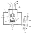
本発明で用いる同軸型真空アーク蒸着源を備えた真空チャンバからなる蒸着装置の一構成例について、図2を参照して、以下説明する。 A configuration example of a vapor deposition apparatus including a vacuum chamber provided with a coaxial vacuum arc vapor deposition source used in the present invention will be described below with reference to FIG.
カソード12は、円柱状であり、全体が上記したような触媒金属材料で構成されていてもよいし、一端がこれらの触媒金属材料で構成され、他端が棒状電極で構成されていてもよい。カソード12は、触媒金属材料が真空チャンバ2内部へ放出され、被処理基体である担体表面に供給され得るように、担体に対向して設置されることが好ましい。このカソード12は、円筒状のトリガ電極13と円筒状の絶縁碍子(以下、ハット型碍子と称す)14とに密接して挿通されている。
The
かくして、本発明で用いる同軸型真空アーク蒸着源は、円筒状のトリガ電極13と円柱状のカソード12とが円筒状のハット型碍子14を介して同軸状に隣接して固定されて配置され、円柱状のカソード12の周りに同軸状に円筒状のアノード11が離間して配置されるように構成されている。
Thus, the coaxial vacuum arc vapor deposition source used in the present invention is arranged such that the
ハット型碍子14は、カソード12とトリガ電極13との間に配置されており、中心からカソード12、ハット型碍子14、トリガ電極13の順序で並んでいる。カソード12とハット型碍子14とトリガ電極13との3つの部品は、密着させ、図示していないが、ネジ等で密着、固定させて取り付けられている。アノード11及びトリガ電極13の材質は、例えばステンレスであり、また、ハット型碍子の材質は、例えばアルミナである。
The hat-
アノード11とトリガ電極13とカソード12とは、相互に絶縁されており、カソード12とアノード11との間には、直流電源15aとコンデンサユニット15bとを有するアーク電源が接続され、トリガ電極13にはトリガ電源16が接続され、各電極11、12には異なる電圧が印加できるように構成されている。このコンデンサユニット15bは、複数のコンデンサを複数並列に接続してなるユニットである。図2には1つのコンデンサを示してあるが、コンデンサの数は、適宜、用途に応じて増減可能である。例えば、1つの容量が360μF(耐圧:400V)のコンデンサを5つ並列に接続すれば容量1800μFとなり、3つ並列に接続すれば容量1080μFとして使用することもできる。また、2200μF(耐圧100V)のコンデンサを4つ並列に接続し、容量8800μFとして使用することもできる。
The
コンデンサユニット15bの各端部は、それぞれがアノード11、カソード12に接続され、コンデンサユニット15bと直流電源15aとは、並列接続されている。直流電源15aは、例えば、100Vで数Aの電流を流す能力を有する電源であり、コンデンサユニット15bに対して、一定の充電時間で充電されるように構成されている。
Each end of the
トリガ電源16は、パルストランスからなり、入力200Vのμsのパルス電圧を約17倍に変圧して3.4kV(数μA)、極性:プラスにして出力できるように構成されており、変圧された電圧を、カソード12に対して正の極性となるトリガ電極13に印加できるように接続されている。すなわち、トリガ電源16のプラス出力端子は、トリガ電極13に接続され、そのマイナス端子は、アーク電源(直流電源15a)のマイナス出力側端子と同じ電位に接続されて、カソード12に接続されている。直流電源15aのプラス端子は、グランド電位に接地され、アノード11に接続されている。また、コンデンサユニットの両端子は、直流電源15aのプラス及びマイナス端子間に接続されている。
The
上記したように構成されている同軸型真空アーク蒸着源1は、所定の真空排気系(例えば、ターボ分子ポンプとロータリーポンプとで構成されている。)を有する真空チャンバ2の壁面に取り付けられ、本発明の排ガス触媒を形成するために用いられる。この同軸型真空アーク蒸着源1は、1つでも複数でも、適宜、設置することが可能である。また、アノード11と真空チャンバ2とは接地電位に接続されている。
The coaxial vacuum arc deposition source 1 configured as described above is attached to the wall surface of a
真空チャンバ2内には、同軸型真空アーク蒸着源1に対向して、担体の粉末21を収容する攪拌容器22を載置するためのステージ23が設置されている。この攪拌容器22は収容された担体の粉末21を均一に攪拌するための手段を備えている。すなわち、図2では、攪拌容器22は攪拌用の固定羽根24を備え、ステージ23の下面中心にステージ、ひいては攪拌容器を回転自在にするための回転機構25が接続されている。この回転機構25により攪拌容器22を回転させ、固定羽根24により、担体の粉末21を均一に攪拌できるように構成されている。この場合、攪拌容器22内の担体の粉末21が均一に攪拌される手段を設けてあればよく、例えば、攪拌容器22を固定し、攪拌手段により攪拌できるように構成してもよい。
In the
また、真空チャンバ2の壁面には、バルブ26a、ターボ分子ポンプ26b、バルブ26c及びロータリーポンプ26dからなる真空排気系がこの順序で金属製配管により接続されている。この真空排気系により、真空チャンバ2内を真空排気し、このチャンバ内を10−5Pa以下に保つことができるように構成されている。
Further, a vacuum exhaust system including a
上記した同軸型真空アーク蒸着源は、スパッタ法に比べて粒子の持つエネルギーが高いことが知られており、また、真空雰囲気中での蒸着処理であるため、不純物が少ないという特徴をもっている。 The coaxial vacuum arc vapor deposition source described above is known to have higher energy of particles than the sputtering method, and has a feature that there are few impurities because it is a vapor deposition treatment in a vacuum atmosphere.
本発明によれば、真空排気し、所定の真空雰囲気が形成されている真空チャンバ2内へ、同軸型真空アーク蒸着源1の作動により生成した触媒金属材料の荷電粒子を放出して、真空チャンバ2内に載置されている担体表面へ供給し、担体表面上に触媒金属ナノ粒子を蒸着形成する。
以下、本発明で用いる同軸型真空アーク蒸着源1の動作例について説明する。
According to the present invention, the charged particles of the catalytic metal material generated by the operation of the coaxial vacuum arc deposition source 1 are discharged into the
Hereinafter, an operation example of the coaxial vacuum arc deposition source 1 used in the present invention will be described.
先ず、コンデンサユニット15bの容量を360μF以上1080μF以下に設定し、直流電源15aから60〜100Vの電圧を出力し、その電圧でコンデンサユニット15bを充電し、アノード11とカソード12との間にコンデンサユニット15bの充電電圧を印加する。触媒金属材料からなる蒸発材料部材に、コンデンサユニット15bが出力する負電圧を印加する。
First, the capacitance of the
上記したような電圧印加の状態で、トリガ電源16から3.4kVのパルス状のトリガ電圧を出力し、カソード12とトリガ電極13との間に印加すると、ハット型碍子14の表面でトリガ放電(沿面放電)が発生する。カソード12とハット型碍子14のつなぎ目からは電子が放出される。
When a pulsed trigger voltage of 3.4 kV is output from the
このトリガ放電によってアノード11とカソード12との間の耐電圧が低下し、アノード11の内周面とカソード12の外周面(側面)との間にアーク放電が誘起される。
With this trigger discharge, the withstand voltage between the
コンデンサユニット15bに充電された電荷の放電により、尖頭電流が1800A以上であるアーク電流が200μ秒程度の時間流れ、カソード12(すなわち、蒸発材料部材である触媒金属材料)の中心軸線上に多量の電流(2000A〜5000A)が200μs〜550μsの間流れるので、カソード近傍に磁場が形成されると共に、その側面から真空チャンバ2内に放出された金属蒸気により、金属のプラズマが形成される。この時発生したプラズマ中の電子(この電子は、カソードからアノードの円筒内面を飛行する)は、自己形成した磁場によって電流が流れる向きとは逆向きのローレンツ力を受け、前方に飛行し、真空チャンバ2内へ放出され、一方、プラズマ中のカソードを構成する触媒金属のイオンは、前記したように電子が飛行し分極することでクーロン力により前方の電子に引きつけられるようにして前方に飛行し、ステージ23に対向するアノード11の放出口11aから真空チャンバ2内に放出される。
Due to the discharge of the electric charge charged in the
1回のトリガ放電でアーク放電が一回誘起され、アーク電流が300μs流れる。上記コンデンサユニット15bの充電時間が約1秒である場合、1Hzの周期でアーク放電を誘起させることができる。アーク放電を所定の回数誘起させて、所定のショット数(発数)で担体表面に触媒金属ナノ粒子を担持せしめる。
An arc discharge is induced once by one trigger discharge, and an arc current flows for 300 μs. When the charging time of the
以上では、同軸型真空アーク蒸着源を用いれば、ヒーターなどの加熱手段である熱源で担体を加熱することなく、触媒金属ナノ粒子を形成できるということについて説明したが、熱源により所定の温度に加熱した担体を用いる場合でも、加熱することなく実施した場合と同様に、触媒金属ナノ粒子を担持せしめることはできる。 As described above, it has been explained that if a coaxial vacuum arc deposition source is used, the catalytic metal nanoparticles can be formed without heating the carrier with a heat source which is a heating means such as a heater. Even when the support is used, catalytic metal nanoparticles can be supported in the same manner as in the case of carrying out without heating.
図2において、マスフローメータ27a、バルブ27b、ガスボンベ27cは、真空チャンバ2内へガスを導入することが必要になる場合のために設けられている。
In FIG. 2, a
以下、実施例及び比較例を挙げて、本発明について詳細に説明する。以下の実施例及び比較例では、触媒金属材料としてPtを用い、担体としてアルミナ粉+La2O3粉を用い、この担体粒子の表面上にPtナノ粒子を蒸着せしめた。上記した他の触媒金属材料でも他の担体/担体配合量でも、同軸型真空アーク蒸着源を用いて、同様に触媒活性に優れた排ガス触媒を形成できる。実施例に挙げたものに限定されず、また、放電条件も、同軸型真空アーク蒸着源を用いて同様に金属ナノ粒子が形成できる条件範囲であればよく、以下の実施例記載の条件に限定されない。 Hereinafter, the present invention will be described in detail with reference to examples and comparative examples. In the following examples and comparative examples, Pt was used as the catalyst metal material, alumina powder + La 2 O 3 powder was used as the support, and Pt nanoparticles were deposited on the surface of the support particles. An exhaust gas catalyst having excellent catalytic activity can be formed using the coaxial vacuum arc deposition source in the same manner with the above-described other catalytic metal materials and other carrier / carrier blend amounts. The discharge conditions are not limited to those described in the examples, and the discharge conditions may be in a range in which metal nanoparticles can be similarly formed using a coaxial vacuum arc deposition source, and are limited to the conditions described in the following examples. Not.
同軸型真空アーク蒸着源((株)アルバック製:ARL−300)を備えた蒸着装置として、図2に模式的に示す装置を用い、アルミナ(Al2O3)粉97wt%にLa2O3粉3wt%を添加した担体を4g用い、以下記載するようにして、この担体の粒子の表面上にPtナノ粒子を0.2wt%担持せしめた。 As a vapor deposition apparatus equipped with a coaxial vacuum arc vapor deposition source (manufactured by ULVAC, Inc .: ARL-300), an apparatus schematically shown in FIG. 2 is used, and La 2 O 3 is added to 97 wt% of alumina (Al 2 O 3 ) powder. 4 g of the carrier added with 3 wt% of powder was used, and 0.2 wt% of Pt nanoparticles were supported on the surface of the particles of the carrier as described below.
すなわち、パラメータとして、コンデンサユニット15bの容量:1080μF、放電電圧:100V、周波数:4Hzの条件で、トリガ電源16から3.4kVのパルス状のトリガ電圧を出力して、トリガ放電を発生せしめ、このトリガ放電によって誘起されたアーク放電を所定の回数行い、所定のショット数(4850発)で、攪拌容器22内に収容された担体の粉末21を均一に攪拌しながら、担体の表面上にPtナノ粒子(粒径2〜3nm)を蒸着形成せしめた。かくして得られた排ガス触媒は、担体表面にPtナノ粒子が0.2wt%担持されている0.2Pt/La2O3−Al2O3の組成を有していた。
That is, as a parameter, a trigger voltage is generated by outputting a 3.4 kV pulsed trigger voltage from the
次に、流通反応装置を用いて、この装置内に上記のようにして製造されたPtの担持された排ガス触媒を0.05g載置し、この触媒に対して、0.05%NO、0.51%CO、0.0394%C3H6、0.4%O2、残部Heからなるガス(ガソリン自動車用三元触媒評価用ガス)を流速100mL/minで流し(W/F=5.00×10−4g・min・cm−3)、触媒温度を600℃まで昇温させながら(10℃/min)、昇温反応特性である各温度における反応率(%)から触媒活性を評価した。この場合、上記のようにして製造したままのPt担持触媒自体(高温水蒸気未処理)と、担持後に高温水蒸気処理(900℃、25時間、10%H2O/air)を行って得たPt担持触媒とについて評価した。
Next, 0.05 g of Pt-supported exhaust gas catalyst produced as described above was placed in this apparatus using a flow reactor, and 0.05% NO, 0% was added to this catalyst. .51% CO, 0.0394% C 3 H 6, 0.4
得られた結果を、横軸に反応温度(℃)、縦軸に反応率(%)をとり、図3(a)及び図4(a)にプロットした。図3(a)は高温水蒸気未処理の場合の結果であり、図4(a)は高温水蒸気処理した場合の結果である。なお、図3(a)及び図4(a)において、APG(アークプラズマガン)は、同軸型真空アーク蒸着を用いてPtを担持させた場合を示す。 The obtained results are plotted in FIG. 3A and FIG. 4A with the reaction temperature (° C.) on the horizontal axis and the reaction rate (%) on the vertical axis. FIG. 3A shows the result when high-temperature steam is not treated, and FIG. 4A shows the result when high-temperature steam is treated. In FIGS. 3A and 4A, APG (arc plasma gun) shows a case where Pt is carried using coaxial vacuum arc deposition.
実施例1におけるPtの代わりにPdを用い、実施例1記載の方法を繰り返した。その結果、0.2Pd/La2O3−Al2O3の組成を有する触媒が得られ、触媒活性は実施例1の場合とほぼ同様であった。 The method described in Example 1 was repeated using Pd instead of Pt in Example 1. As a result, a catalyst having a composition of 0.2 Pd / La 2 O 3 —Al 2 O 3 was obtained, and the catalytic activity was almost the same as in Example 1.
(比較例1)
担持触媒原料としてPt(NH3)2(NO2)2を使用し、La2O3−Al2O3担体にPtを湿式含浸担持させた。すなわち、La2O3−Al2O3担体粉末に所定濃度のPt(NH3)2(NO2)2の水溶液を所定量含浸させ、次いで蒸発乾固させた後に600℃で所定の時間焼成し、Ptを担持せしめ、0.2Pt/La2O3−Al2O3の組成を有するPt担持触媒を調製した。かくして得られたままのPt担持触媒及び担持後に実施例1と同様に高温水蒸気処理を行って得たPt担持触媒について、触媒活性を実施例1記載の方法に従って評価した。
(Comparative Example 1)
Pt (NH 3 ) 2 (NO 2 ) 2 was used as a supported catalyst raw material, and Pt was wet impregnated and supported on a La 2 O 3 —Al 2 O 3 support. That is, a La 2 O 3 —Al 2 O 3 carrier powder is impregnated with a predetermined amount of an aqueous solution of Pt (NH 3 ) 2 (NO 2 ) 2 having a predetermined concentration, and then evaporated to dryness, followed by baking at 600 ° C. for a predetermined time. Then, Pt was supported, and a Pt-supported catalyst having a composition of 0.2 Pt / La 2 O 3 —Al 2 O 3 was prepared. The catalytic activity of the Pt-supported catalyst as obtained and the Pt-supported catalyst obtained by carrying out high-temperature steam treatment in the same manner as in Example 1 after the support was evaluated according to the method described in Example 1.
得られた結果を、横軸に反応温度(℃)、縦軸に反応率(%)をとり、図3(b)及び図4(b)にプロットした。図3(b)は高温水蒸気未処理の場合の結果であり、図4(b)は高温水蒸気処理した場合の結果である。 The obtained results are plotted in FIG. 3B and FIG. 4B, with the reaction temperature (° C.) on the horizontal axis and the reaction rate (%) on the vertical axis. FIG. 3 (b) shows the results when the high-temperature steam is not treated, and FIG. 4 (b) shows the results when the high-temperature steam is treated.
図3(a)及び(b)の結果を比較すると、Pt担持後に高温水蒸気処理を行わなかった場合、同軸型真空アーク蒸着源で担持させた方が、湿式法で担持させた方より低温で反応し易く、高活性であることがわかる。例えば、同軸型真空アーク蒸着源で担持させた場合、全てのガス成分に対して、300℃では反応率が10%前後、高温領域である400℃では反応率が80%前後、さらに500℃では反応率がほぼ100%であるのに対して、湿式法で担持させた場合、全てのガス成分に対して、300℃では反応率が0%、高温領域である400℃では反応率が20%前後と低く、500℃でも反応率はほぼ80%であることがわかる。 Comparing the results of FIGS. 3 (a) and 3 (b), when high-temperature steam treatment was not performed after Pt support, the support with the coaxial vacuum arc deposition source was performed at a lower temperature than the support with the wet method. It is easy to react and it turns out that it is highly active. For example, when supported by a coaxial vacuum arc deposition source, for all gas components, the reaction rate is around 10% at 300 ° C, the reaction rate is around 80% at 400 ° C in the high temperature region, and further at 500 ° C. While the reaction rate is almost 100%, when supported by a wet method, the reaction rate is 0% at 300 ° C. and the reaction rate is 20% at 400 ° C. in the high temperature range for all gas components. It can be seen that the reaction rate is almost 80% even at 500 ° C.
また、図4(a)及び(b)の結果を比較すると、Pt担持後に高温水蒸気処理を行った場合、同軸型真空アーク蒸着源で担持させた方が、湿式法で担持させた方より低温で反応し易いことがわかる。同軸型真空アーク蒸着源で担持させた場合、高温水蒸気処理を行わなかった場合と比べて触媒活性は劣化しているが、全てのガス成分に対して、湿式法で担持させた場合よりも高温領域(400℃以上)でも高活性である。一方、湿式法で担持させた場合、高温水蒸気処理によって反応開始温度が上昇し、触媒活性が劣化しており、全てのガス成分に対して、400℃でも反応率が10%前後と低く、同軸型真空アーク蒸着源で担持させた場合と比べて同じ反応率を得るのに高温である必要があり、600℃でも反応率は80%以下であった。 4 (a) and 4 (b), when high-temperature steam treatment is performed after supporting Pt, the temperature supported by the coaxial vacuum arc deposition source is lower than that supported by the wet method. It turns out that it is easy to react. When supported by a coaxial vacuum arc deposition source, the catalytic activity is deteriorated compared to the case where high-temperature steam treatment is not performed, but for all gas components, the temperature is higher than when supported by a wet method. It is highly active even in the region (400 ° C. or higher). On the other hand, when it is supported by a wet method, the reaction start temperature is increased by high-temperature steam treatment, the catalytic activity is deteriorated, and the reaction rate is low at around 10% even at 400 ° C. for all gas components. In order to obtain the same reaction rate as compared with the case where it was supported by a mold type vacuum arc vapor deposition source, it was necessary to be at a high temperature, and the reaction rate was 80% or less even at 600 ° C.
(比較例2)
特開2005−125259号公報記載のレーザーアブレーション法に準じて、担体表面にPtを担持せしめ、ガス浄化材料を製造した。
(Comparative Example 2)
In accordance with the laser ablation method described in JP-A-2005-125259, Pt was supported on the surface of the carrier to produce a gas purification material.
すなわち、特開2005−125259号公報記載の実施例の方法に準じ、La2O3−Al2O3担体、蒸留水からスラリーを調製した。得られたスラリーをハニカムプレートの表面に塗布した後、120℃で3時間乾燥し、更に空気気流中において450℃で2時間焼成し、金属酸化物担体を得た。このようにして得られた金属酸化物担体を用いて、YAGレーザー光源、ターゲットとして白金板を用い、真空度下で、ターゲット及び担体を所定の回転数で回転させた状態で、レーザー光源から所定の条件でパルスレーザー光をターゲットに60秒間照射した。その結果、担体の表面に白金微粒子からなる白金薄膜が形成された。この白金担持担体に対して、水素と窒素との混合ガス(水素含有量:5容量%)中において500℃で2時間の水素還元処理を施し、Pt担持触媒を製造した。 That is, a slurry was prepared from a La 2 O 3 —Al 2 O 3 carrier and distilled water according to the method of the examples described in JP-A-2005-125259. The obtained slurry was applied to the surface of the honeycomb plate, dried at 120 ° C. for 3 hours, and further fired in an air stream at 450 ° C. for 2 hours to obtain a metal oxide carrier. Using the metal oxide support thus obtained, a YAG laser light source, a platinum plate as a target, a target and a carrier are rotated at a predetermined number of revolutions under a vacuum, and the laser light source is used. The target was irradiated with pulsed laser light for 60 seconds under the conditions described above. As a result, a platinum thin film made of platinum fine particles was formed on the surface of the carrier. The platinum-supported catalyst was subjected to hydrogen reduction treatment at 500 ° C. for 2 hours in a mixed gas of hydrogen and nitrogen (hydrogen content: 5% by volume) to produce a Pt-supported catalyst.
かくして得られたPt担持触媒に対して、触媒活性を実施例1記載の方法に従って評価した。得られた結果は、比較例1の湿式法の場合とほぼ同様であった。 The catalytic activity of the Pt-supported catalyst thus obtained was evaluated according to the method described in Example 1. The obtained results were almost the same as in the wet method of Comparative Example 1.
本実施例では、コンデンサユニット15bの容量を360μF、720μF、1440μFに設定し、放電電圧を60V、150Vとしたことを除いて、実施例1記載の方法を繰り返し、Pt担持触媒を調製した。
In this example, the Pt-supported catalyst was prepared by repeating the method described in Example 1 except that the capacity of the
かくして得られたPt担持触媒について、触媒活性を実施例1記載の方法に従って評価した。その結果、360μF、720μF、60Vの場合は実施例1の場合と同様な傾向が得られたが、1440μF、150Vの場合は、実施例1の場合より触媒活性は劣っていた。 The catalytic activity of the Pt-supported catalyst thus obtained was evaluated according to the method described in Example 1. As a result, in the case of 360 μF, 720 μF, and 60 V, the same tendency as in Example 1 was obtained, but in the case of 1440 μF and 150 V, the catalytic activity was inferior to that in Example 1.
本発明によれば、同軸型真空アーク蒸着源を用いることにより、高温領域で高活性な金属ナノ粒子担持触媒を提供できるので、本発明は、特に自動車やオートバイ、ボイラ等の内燃機関からの排ガスを処理するための触媒技術分野での利用が可能である。 According to the present invention, by using a coaxial vacuum arc deposition source, a metal nanoparticle-supported catalyst that is highly active in a high temperature region can be provided. Therefore, the present invention is particularly effective for exhaust gas from internal combustion engines such as automobiles, motorcycles, and boilers. Can be used in the field of catalyst technology.
1 同軸型真空アーク蒸着源 2 真空チャンバ
11 アノード 11a 放出口
12 カソード 13 トリガ電極
14 ハット型碍子 15a 直流電源
15b コンデンサユニット 16 トリガ電源
21 担体の粉末 22 攪拌容器
23 ステージ 24 固定羽根
25 回転機構 26a、26c バルブ
26b ターボ分子ポンプ 26d ロータリーポンプ
27a マスフローメータ 27b バルブ
27c ガスボンベ
DESCRIPTION OF SYMBOLS 1 Coaxial type vacuum
Claims (2)
The method for producing an exhaust gas catalyst according to claim 1, wherein the catalytic metal material is at least one metal selected from Pd, Pt, Co, Ag, and Rh, or an alloy composed of two or more of these metals. A method for producing an exhaust gas catalyst.
Priority Applications (1)
| Application Number | Priority Date | Filing Date | Title |
|---|---|---|---|
| JP2008320327A JP2010142699A (en) | 2008-12-16 | 2008-12-16 | Method for producing exhaust gas catalyst by using coaxial vacuum arc vapor deposition source |
Applications Claiming Priority (1)
| Application Number | Priority Date | Filing Date | Title |
|---|---|---|---|
| JP2008320327A JP2010142699A (en) | 2008-12-16 | 2008-12-16 | Method for producing exhaust gas catalyst by using coaxial vacuum arc vapor deposition source |
Publications (1)
| Publication Number | Publication Date |
|---|---|
| JP2010142699A true JP2010142699A (en) | 2010-07-01 |
Family
ID=42563688
Family Applications (1)
| Application Number | Title | Priority Date | Filing Date |
|---|---|---|---|
| JP2008320327A Pending JP2010142699A (en) | 2008-12-16 | 2008-12-16 | Method for producing exhaust gas catalyst by using coaxial vacuum arc vapor deposition source |
Country Status (1)
| Country | Link |
|---|---|
| JP (1) | JP2010142699A (en) |
Cited By (3)
| Publication number | Priority date | Publication date | Assignee | Title |
|---|---|---|---|---|
| CN103933974A (en) * | 2014-05-05 | 2014-07-23 | 中国石油大学(华东) | Preparation method for supported type palladium catalyst |
| JP2016035100A (en) * | 2014-08-01 | 2016-03-17 | アドバンス理工株式会社 | Ionic liquid material and method for producing the ionic liquid material |
| JP2021133331A (en) * | 2020-02-28 | 2021-09-13 | いすゞ自動車株式会社 | Catalyst members, catalysts, and methods for manufacturing catalyst members |
Citations (4)
| Publication number | Priority date | Publication date | Assignee | Title |
|---|---|---|---|---|
| JPH0899039A (en) * | 1994-09-30 | 1996-04-16 | Daiki Gomme Kogyo Kk | Amorphous alloy catalyst for nitrogen oxide decomposition |
| JPH09141092A (en) * | 1995-11-20 | 1997-06-03 | Hino Motors Ltd | Exhaust gas purification catalyst and its production |
| JP2005125259A (en) * | 2003-10-24 | 2005-05-19 | Toyota Central Res & Dev Lab Inc | Gas purification material and method for producing the same |
| JP2008266747A (en) * | 2007-04-24 | 2008-11-06 | Ulvac Japan Ltd | Alloy nanoparticle preparation method, alloy thin film preparation method, and coaxial vacuum arc deposition apparatus |
-
2008
- 2008-12-16 JP JP2008320327A patent/JP2010142699A/en active Pending
Patent Citations (4)
| Publication number | Priority date | Publication date | Assignee | Title |
|---|---|---|---|---|
| JPH0899039A (en) * | 1994-09-30 | 1996-04-16 | Daiki Gomme Kogyo Kk | Amorphous alloy catalyst for nitrogen oxide decomposition |
| JPH09141092A (en) * | 1995-11-20 | 1997-06-03 | Hino Motors Ltd | Exhaust gas purification catalyst and its production |
| JP2005125259A (en) * | 2003-10-24 | 2005-05-19 | Toyota Central Res & Dev Lab Inc | Gas purification material and method for producing the same |
| JP2008266747A (en) * | 2007-04-24 | 2008-11-06 | Ulvac Japan Ltd | Alloy nanoparticle preparation method, alloy thin film preparation method, and coaxial vacuum arc deposition apparatus |
Cited By (5)
| Publication number | Priority date | Publication date | Assignee | Title |
|---|---|---|---|---|
| CN103933974A (en) * | 2014-05-05 | 2014-07-23 | 中国石油大学(华东) | Preparation method for supported type palladium catalyst |
| CN103933974B (en) * | 2014-05-05 | 2015-05-20 | 中国石油大学(华东) | Preparation method for supported type palladium catalyst |
| JP2016035100A (en) * | 2014-08-01 | 2016-03-17 | アドバンス理工株式会社 | Ionic liquid material and method for producing the ionic liquid material |
| JP2021133331A (en) * | 2020-02-28 | 2021-09-13 | いすゞ自動車株式会社 | Catalyst members, catalysts, and methods for manufacturing catalyst members |
| JP7419107B2 (en) | 2020-02-28 | 2024-01-22 | いすゞ自動車株式会社 | Method for manufacturing catalyst members |
Similar Documents
| Publication | Publication Date | Title |
|---|---|---|
| JP2017200674A (en) | Oxidation catalyst | |
| US20210394196A1 (en) | System and method for purifying engine exhaust by using ozone | |
| JP2010142699A (en) | Method for producing exhaust gas catalyst by using coaxial vacuum arc vapor deposition source | |
| JP6789491B2 (en) | Metal foil catalyst and its manufacturing method, and catalyst converter | |
| JP3626971B2 (en) | Chemical reactor | |
| JP5422281B2 (en) | Hydrogen gas sensor and method for manufacturing hydrogen gas sensor | |
| JP5188053B2 (en) | Nanoparticle production method | |
| JP6161053B2 (en) | Vapor deposition source and fine particle forming device | |
| JP6583735B2 (en) | Dehydrogenation catalyst for organic hydride and method for producing the same | |
| JP3337473B2 (en) | Method and apparatus for generating negatively charged oxygen atoms | |
| JP2008231502A (en) | Powder agitation mechanism, method for producing metallic particulate carrying powder and catalyst for fuel cell | |
| JP2008311054A (en) | Catalyst material and production method thereof | |
| WO2013037087A1 (en) | Preparation method for catalyst on surface of work piece in combustion chamber of internal combustion engine | |
| JP6575924B2 (en) | NOx purification device and NOx purification method using the same | |
| JP5252362B2 (en) | Ceramic electrode | |
| JP4466760B2 (en) | Electrocatalyst production method | |
| JP2009285644A (en) | Manufacturing method of catalyst material and vacuum arc evaporation device | |
| JP2005087864A (en) | Manufacturing method of electrode catalyst | |
| JP2008110277A (en) | Low temperature operation type electrochemical reactor | |
| RU2401699C1 (en) | Method of forming active layer of tubular catalyst | |
| JP6285065B1 (en) | Metal nanoparticle manufacturing method and manufacturing apparatus thereof | |
| CN114797464A (en) | Device and method for online elimination of CO based on plasma technology | |
| KR100686021B1 (en) | Air purifier using yttrium oxide (# 2O3) | |
| JP2016035100A (en) | Ionic liquid material and method for producing the ionic liquid material | |
| JP5016976B2 (en) | Method for producing fine particle film |
Legal Events
| Date | Code | Title | Description |
|---|---|---|---|
| A621 | Written request for application examination |
Free format text: JAPANESE INTERMEDIATE CODE: A621 Effective date: 20111018 |
|
| A02 | Decision of refusal |
Free format text: JAPANESE INTERMEDIATE CODE: A02 Effective date: 20130515 |