JP2010142469A - Portal clothes drying pole - Google Patents

Portal clothes drying pole Download PDF

Info

Publication number
JP2010142469A
JP2010142469A JP2008324032A JP2008324032A JP2010142469A JP 2010142469 A JP2010142469 A JP 2010142469A JP 2008324032 A JP2008324032 A JP 2008324032A JP 2008324032 A JP2008324032 A JP 2008324032A JP 2010142469 A JP2010142469 A JP 2010142469A
Authority
JP
Japan
Prior art keywords
gate
column
movable
support
clothes drying
Prior art date
Legal status (The legal status is an assumption and is not a legal conclusion. Google has not performed a legal analysis and makes no representation as to the accuracy of the status listed.)
Pending
Application number
JP2008324032A
Other languages
Japanese (ja)
Inventor
Masahiro Totake
政広 都竹
Takafumi Toyoyoshi
隆文 豊吉
Current Assignee (The listed assignees may be inaccurate. Google has not performed a legal analysis and makes no representation or warranty as to the accuracy of the list.)
MINO CRAFT KK
Original Assignee
MINO CRAFT KK
Priority date (The priority date is an assumption and is not a legal conclusion. Google has not performed a legal analysis and makes no representation as to the accuracy of the date listed.)
Filing date
Publication date
Application filed by MINO CRAFT KK filed Critical MINO CRAFT KK
Priority to JP2008324032A priority Critical patent/JP2010142469A/en
Publication of JP2010142469A publication Critical patent/JP2010142469A/en
Pending legal-status Critical Current

Links

Images

Landscapes

  • Holders For Apparel And Elements Relating To Apparel (AREA)

Abstract

<P>PROBLEM TO BE SOLVED: To provide a portal clothes drying pole having an improved original function as a clothes drying pole by suitably changing the direction of a window 1a by the turning of a portal member 1, also providing another function as a decoration for a garden or the like by varying the appearance of the garden or the like where the portal member 1 is set, and stabilizing the turning of the portal member 1 by movable columns 4. <P>SOLUTION: The movable columns 4 are placed in a horizontal direction to a standing central column 2 and joined to the column with a horizontal member 3, the movable column 4 is turnably provided around an axis 2a of the central column 2 via the horizontal member 3, and a supporting arm 8 which bridges a wash-line pole 10 by the window 1a provided inside the portal member 1 formed by the central column 2, the movable column 4, and the horizontal member 3 is provided in the central column 2 and the movable column 4 of the portal member 1. <P>COPYRIGHT: (C)2010,JPO&amp;INPIT

Description

本発明は物干し具の形態の改良に関するものである。   The present invention relates to an improvement in the form of a clothesline.

従来、下記特許文献1にかかる物干し具では、複数の物干し竿を外周に配設した一本の支柱が基台に対し回転自在に立設されている。
実開昭63−129593号公報
Conventionally, in the clothesliner according to Patent Document 1 below, a single support having a plurality of clothespins arranged on the outer periphery is erected so as to be rotatable with respect to the base.
Japanese Utility Model Publication No. 63-129593

上記特許文献1にかかる物干し具は、一本の支柱の外周に複数の物干し竿を配設した構造を有しているに過ぎず、支柱を回動させても外観上は外周の各物干し竿だけが目立ち、物干しとしての本来の機能しか発揮することができない。   The clothesliner according to Patent Document 1 has only a structure in which a plurality of clothespins are arranged on the outer periphery of a single support column. Even if the support column is rotated, the appearance of each clothesline on the outer periphery is shown. Only stands out and can only demonstrate its original function as a clothesline.

この発明は、物干し具としての機能を高めることを目的としている。   This invention aims at improving the function as a clothes-drying tool.

後記実施形態の図面(図1〜6)の符号を援用して本発明を説明する。
請求項1の発明にかかる門形物干し具においては、立設した中心支柱2に対し可動支柱4を横方向に並べて横部材3により連結するとともにこの可動支柱4をその中心支柱2の軸線2aを中心に横部材3を介して回動し得るように立設し、この中心支柱2と可動支柱4と横部材3とにより形成した門形部材1の内側に設けた窓1aで物干し竿10を支持し得る支持腕8をこの門形部材1に設けた。請求項1の発明では、門形部材1の回動により窓1aの向きを適宜変更することにより、物干しとしての本来の機能を高めるばかりでなく、門形部材1を設置した庭等の外観に変化を与えて、物干し具に対し庭等の装飾用品としての別機能をも持たせることができる。また、可動支柱4により門形部材1の回動を安定させることができる。
The present invention will be described with reference to the reference numerals of the drawings (FIGS. 1 to 6) of the embodiments described later.
In the portal drying apparatus according to the first aspect of the present invention, the movable support column 4 is arranged in the horizontal direction with respect to the upright central support column 2 and connected by the horizontal member 3, and the movable support column 4 is connected to the axis 2a of the central support column 2. A clothes rack 10 is installed in a window 1a provided on the inner side of a gate-shaped member 1 which is erected so as to be able to rotate at the center via a horizontal member 3 and which is formed by the central column 2, the movable column 4, and the horizontal member 3. A supporting arm 8 capable of supporting was provided on the portal member 1. In the invention of claim 1, by appropriately changing the direction of the window 1a by the rotation of the gate-shaped member 1, not only the original function as a clothesline is improved, but also the appearance of a garden or the like in which the gate-shaped member 1 is installed. By giving changes, it is possible to give the clothesliner another function as a decorative article such as a garden. Further, the movable column 4 can stabilize the rotation of the gate-shaped member 1.

請求項1の発明を前提とする請求項2の発明において、前記支持腕8は中心支柱2と可動支柱4とにそれぞれ設けられて互いに横方向に並べられ、中心支柱2側の支持腕8と可動支柱4側の支持腕8との間で物干し竿10を架設し得る。請求項2の発明では、門形部材1の窓1aを有効利用して物干し竿10を支持することができる。   In the invention of claim 2 premised on the invention of claim 1, the support arms 8 are respectively provided on the central support column 2 and the movable support column 4 and are arranged side by side, and the support arm 8 on the center support column 2 side A laundry basket 10 can be installed between the support arm 8 on the movable support column 4 side. According to the second aspect of the present invention, the laundry basket 10 can be supported by effectively utilizing the window 1a of the gate-shaped member 1.

請求項1または請求項2の発明を前提とする請求項3の発明において、前記中心支柱2は回動支持部5上に立設されてその軸線2a回りで回動可能に支持されている。請求項3の発明では、回動支持部5上に中心支柱2を立設して回動支持部5に対し回動可能に支持するだけの簡単な構造により、門形部材1を回動させることができる。   In the invention of claim 3 which presupposes the invention of claim 1 or claim 2, the central support column 2 is erected on the rotation support portion 5 and supported so as to be rotatable about its axis 2a. In the invention of claim 3, the gate-shaped member 1 is rotated by a simple structure in which the central support column 2 is erected on the rotation support portion 5 and is supported rotatably with respect to the rotation support portion 5. be able to.

請求項1または請求項2または請求項3の発明を前提とする請求項4の発明において、前記門形部材1には柔軟シ−ト12を収容し得る収容部13を設けてその収容部13から柔軟シ−ト12を前記窓1aに引き出せるようにした。請求項4の発明では、物干し具において柔軟シ−ト12を各種目的に利用することができる。   In the invention of claim 4 based on the invention of claim 1 or claim 2 or claim 3, the portal member 1 is provided with a receiving portion 13 capable of receiving the flexible sheet 12, and the receiving portion 13 is provided. The flexible sheet 12 can be pulled out to the window 1a. In the invention of claim 4, the flexible sheet 12 can be used for various purposes in the clothesline.

請求項1から請求項4のうちいずれか一つの請求項の発明を前提とする請求項5の発明において、前記門形部材1には載置台15を設けた。請求項5の発明では、物干し具において載置台15を各種目的に利用することができる。   In the invention of claim 5 premised on the invention of any one of claims 1 to 4, a mounting table 15 is provided on the gate-shaped member 1. In invention of Claim 5, the mounting base 15 can be utilized for various purposes in the clothes drying tool.

本発明は、物干しとしての本来の機能に庭等の装飾用品としての別機能をも持たせて、物干し具としての機能を高めることができる。   According to the present invention, the function as a clothes drying tool can be enhanced by providing the original function as clothes drying with another function as a decorative article such as a garden.

以下、本発明の一実施形態に係る門形物干し具について図1〜6を参照して説明する。
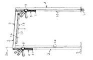
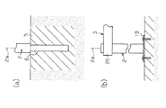
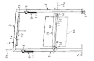
図1に示す門形部材1は中心支柱2と横部材3と可動支柱4とにより互いに門形状に組まれ、この門形部材1の内側には中心支柱2と横部材3と可動支柱4との間で空間である窓1aが形成されている。図2(a)に示すように、庭等の地面に埋設されたコンクリートからなる回動支持部5に支持孔6が形成されている。前記中心支柱2は、この回動支持部5の支持孔6に対し着脱可能に挿嵌されて立設され、軸線2a回りで回動可能に支持されている。この中心支柱2の上端部に前記横部材3の基端部が一体的に連結されている。前記可動支柱4は中心支柱2に対し横方向に並べられて立設され、この可動支柱4の上端部に横部材3の先端部が一体的に連結されている。この可動支柱4の下端部には車輪7が庭等の地面に接した状態で取り付けられている。この可動支柱4は中心支柱2の軸線2aを中心に横部材3を介して360度範囲で回動し得る。この可動支柱4の回動位置の設定時には可動支柱4が庭等の地面に対しロックされて可動支柱4及びその車輪7が位置決めされる。
Hereinafter, the portal-shaped clothes-drying tool which concerns on one Embodiment of this invention is demonstrated with reference to FIGS.
A portal-shaped member 1 shown in FIG. 1 is assembled in a gate shape with a central column 2, a lateral member 3, and a movable column 4, and the central column 2, the lateral member 3, and the movable column 4 are arranged inside the portal-shaped member 1. A window 1a which is a space is formed. As shown to Fig.2 (a), the support hole 6 is formed in the rotation support part 5 which consists of concrete embed | buried under the grounds, such as a garden. The central support column 2 is detachably inserted into and supported by the support hole 6 of the rotation support portion 5 and is supported so as to be rotatable about the axis 2a. The base end portion of the transverse member 3 is integrally connected to the upper end portion of the central support column 2. The movable support column 4 is erected in a horizontal direction with respect to the central support column 2, and the distal end portion of the horizontal member 3 is integrally connected to the upper end portion of the movable support column 4. A wheel 7 is attached to the lower end portion of the movable support column 4 in contact with the ground such as a garden. The movable support column 4 can be rotated in the range of 360 degrees through the transverse member 3 about the axis 2a of the center support column 2. When the rotational position of the movable support 4 is set, the movable support 4 is locked to the ground such as a garden, and the movable support 4 and its wheel 7 are positioned.

図1及び図3に示すように、前記中心支柱2と可動支柱4とには横部材3よりも下方で支持腕8が傾動支持部9により上下方向へ傾動可能に支持されて互いに横方向に並べられている。この両支持腕8には物干し竿10を着脱可能に挿入して掛けるための複数の掛止孔11が長手方向へ並設されている。この両支持腕8は、中心支柱2及び可動支柱4に沿って傾動支持部9から鉛直方向へ垂れ下がる不使用状態と、水平方向またはその水平方向よりも上方へ傾動支持部9から突出する使用状態とを取り得るように、傾動支持部9でロックされて位置決めされる。物干し竿10はこの使用状態で互いに横方向に並ぶ両支持腕8間に架設される。   As shown in FIGS. 1 and 3, a support arm 8 is supported on the central column 2 and the movable column 4 below the lateral member 3 so as to be tiltable in the vertical direction by the tilting support portion 9, and in the lateral direction. Are lined up. The supporting arms 8 are provided with a plurality of latching holes 11 arranged in parallel in the longitudinal direction for detachably inserting the hanging basket 10 into the support arms 8. The both support arms 8 are not used in a state of hanging vertically from the tilting support portion 9 along the central support column 2 and the movable support column 4, and are used in a state of protruding from the tilting support portion 9 in the horizontal direction or above the horizontal direction. In such a manner, the tilting support portion 9 is locked and positioned. The laundry basket 10 is installed between the support arms 8 arranged in the lateral direction in this use state.

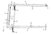
図1及び図4に示すように、前記中心支柱2と可動支柱4との間で横部材3の下側には柔軟シ−ト12を巻いて収容し得る収容部13が取り付けられている。この柔軟シ−ト12が収容部13に収容されて前記門形部材1内の窓1aの全体が開放された状態で、柔軟シ−ト12を収容部13から窓1a側に引き出して適宜引出位置で柔軟シ−ト12を収容部13によりロックして位置決めすると、柔軟シ−ト12により門形部材1内の窓1aの全体または適宜高さまでの一部を閉塞することができる。この柔軟シ−ト12を下方へ若干引いて収容部13によるロックを外すと、柔軟シ−ト12が収容部13内のばねにより収容部13に戻って収容される。   As shown in FIGS. 1 and 4, an accommodating portion 13 that can be accommodated by winding a flexible sheet 12 is attached below the lateral member 3 between the central strut 2 and the movable strut 4. In a state where the flexible sheet 12 is accommodated in the accommodating portion 13 and the entire window 1a in the portal member 1 is opened, the flexible sheet 12 is pulled out from the accommodating portion 13 to the window 1a side and appropriately pulled out. When the flexible sheet 12 is locked and positioned by the accommodating portion 13 at the position, the flexible sheet 12 can block the entire window 1a in the gate-shaped member 1 or a part up to an appropriate height. When the flexible sheet 12 is pulled slightly downward to release the lock by the accommodating portion 13, the flexible sheet 12 is returned to and accommodated in the accommodating portion 13 by the spring in the accommodating portion 13.

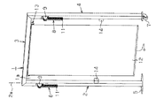
図1及び図5に示すように、前記中心支柱2と可動支柱4とには両支持腕8よりも下方で固定支持部14が横方向に並べられている。この両固定支持部14間に架設される載置台15は、両固定支持部14に対し着脱可能に連結される両端部材16と、この両端部材16に対し軸線17aを中心に回動可能に挿嵌される軸17と、この軸17に対し両端部材16間で一体的に取着されたテーブル18とを備えている。この載置台15が中心支柱2及び可動支柱4の固定支持部14から離脱されて前記門形部材1内の窓1aの全体が開放された状態で、両端部材16を両固定支持部14に連結すると、載置台15が使用状態となる。その使用状態で、軸17を両端部材16に対し軸線17aを中心に回動させると、テーブル18は、軸17から下方へ垂れ下がった状態と軸17から水平に起きた状態とを取り得るように、両端部材16でロックされて位置決めされる。   As shown in FIGS. 1 and 5, the central support 2 and the movable support 4 have fixed support portions 14 arranged in the lateral direction below the support arms 8. The mounting table 15 installed between the both fixed support portions 14 is inserted into both end members 16 that are detachably connected to the both fixed support portions 14 and is rotatable with respect to the both end members 16 about the axis 17a. A shaft 17 to be fitted is provided, and a table 18 that is integrally attached to the shaft 17 between both end members 16. In a state where the mounting table 15 is detached from the fixed support portion 14 of the central support column 2 and the movable support column 4 and the entire window 1a in the portal member 1 is opened, the both end members 16 are connected to the fixed support portions 14. Then, the mounting table 15 becomes in use. When the shaft 17 is rotated with respect to both end members 16 about the axis 17a in the state of use, the table 18 can take a state where it hangs downward from the shaft 17 and a state where it is raised horizontally from the shaft 17. The two end members 16 are locked and positioned.

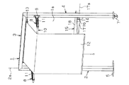
図6に示すように、使用状態で前記両支持腕8間に架設された物干し竿10に前記柔軟シ−ト12を引掛けて屋根として利用することもできる。そのほか、両支持腕8と柔軟シ−ト12とテーブル18とを互いに組み合わせた種々の使用状態で門形部材1を利用することができる。   As shown in FIG. 6, the flexible sheet 12 can be hooked on a clothes rack 10 laid between the two support arms 8 in use and used as a roof. In addition, the portal member 1 can be used in various usage states in which the support arms 8, the flexible sheet 12, and the table 18 are combined with each other.

本実施形態は下記の効果を有する。
* 門形部材1の回動により窓1aの向きを日光の向きに応じて適宜変更することにより、物干しとしての本来の機能を高めることができる。
This embodiment has the following effects.
* The original function as a clothesline can be enhanced by appropriately changing the direction of the window 1a according to the direction of sunlight by turning the gate-shaped member 1.

* 門形部材1の回動により窓1aの向きを適宜変更することにより、門形部材1を設置した庭等の外観に変化を与えて、物干し具に対し庭等の装飾用品としての別機能をも持たせることができるとともに、門形部材1による遮光を防止して庭等に面した部屋へ日光を取り入れ易い。従って、物干し具としての機能を高めることができる。   * By changing the orientation of the window 1a as needed by the rotation of the gate-shaped member 1, the appearance of the garden where the gate-shaped member 1 is installed is changed, and another function as a decorative item such as a garden for the clothesline It is easy to incorporate sunlight into a room facing the garden or the like by preventing the gate-shaped member 1 from shading. Therefore, the function as a clothesliner can be enhanced.

* 門形部材1は可動支柱4により支えられながら中心支柱2を中心に回動するので、門形部材1の回動を安定させることができる。
* 物干し具において、柔軟シ−ト12を各種目的、例えば、庭等に面した部屋への遮光や、庭等の上方を覆う屋根などに利用することができる。
* Since the gate-shaped member 1 rotates around the central column 2 while being supported by the movable column 4, the rotation of the portal-shaped member 1 can be stabilized.
* In the clothes drying tool, the flexible sheet 12 can be used for various purposes, for example, shading the room facing the garden or the roof covering the garden or the like.

* 物干し具において、載置台15を各種目的、例えば、洗濯物の載置や、庭等で食事をする場合における食品の載置などに利用することができる。
前記実施形態以外にも例えば下記のように構成してもよい。
* In the clothes drying tool, the mounting table 15 can be used for various purposes, for example, for placing laundry or placing food in the garden.
For example, the following embodiment may be configured as follows.

・ 図2(b)に示すように、庭等の地面に敷設されたコンクリートに固定された台板19上に中心支柱2を一体的に立設し、この中心支柱2の上端部に対し横部材3の基端部を回動支持部20により回動可能に支持する。この場合も、可動支柱4は中心支柱2の軸線2aを中心に横部材3を介して360度範囲で回動し得る。   As shown in FIG. 2 (b), the central column 2 is integrally erected on the base plate 19 fixed to the concrete laid on the ground such as a garden, and the central column 2 is horizontally disposed with respect to the upper end portion of the central column 2. A base end portion of the member 3 is rotatably supported by the rotation support portion 20. Also in this case, the movable support column 4 can be rotated in the range of 360 degrees through the transverse member 3 around the axis 2a of the center support column 2.

・ 可動支柱4を360度範囲ではなく、例えば180度範囲だけ回動し得るようにする。
・ 物干し竿10を両支持腕8に対し一体的に設ける。
The movable support column 4 can be rotated not in the 360 degree range but in the 180 degree range, for example.
-A clothes-drying basket 10 is provided integrally with both support arms 8.

・ 載置台15において両端部材16を中心支柱2及び可動支柱4の固定支持部14に対し一体的に設ける。   In the mounting table 15, both end members 16 are provided integrally with the central support 2 and the fixed support portion 14 of the movable support 4.

本実施形態にかかる門形物干し具の不使用状態を示す斜視図である。It is a perspective view which shows the non-use state of the gate-shaped clothes drying tool concerning this embodiment. (a)はこの門形物干し具において中心支柱が回動可能に立設された回動支持部を示す部分断面図であり、(b)はこの門形物干し具の別例において中心支柱が立設された支持部と中心支柱に対する横部材の回動支持構造を示す部分断面図である。(A) is a fragmentary sectional view which shows the rotation support part by which the center support | pillar stood so that rotation was possible in this portal-shaped clothes drying tool, (b) is a center support | pillar standing up in another example of this portal-shaped drying tool. It is a fragmentary sectional view which shows the rotation support structure of the horizontal member with respect to the provided support part and center support | pillar. この門形物干し具で物干し竿支持腕の使用状態を示す斜視図である。It is a perspective view which shows the use condition of the laundry basket support arm with this gate-shaped clothes drying tool. この門形物干し具で柔軟シ−トの使用状態を示す斜視図である。It is a perspective view which shows the use condition of a flexible sheet | seat with this gate-shaped clothes drying tool. この門形物干し具で載置台の使用状態を示す斜視図である。It is a perspective view which shows the use condition of a mounting base with this gate-shaped clothes drying tool. この門形物干し具で物干し竿支持腕と柔軟シ−トと載置台の使用状態を示す斜視図である。It is a perspective view which shows the use condition of the clothes-litter support arm, a flexible sheet | seat, and a mounting base with this gate-shaped clothes drying tool.

符号の説明Explanation of symbols

1…門形部材、1a…門形部材の窓、2…中心支柱、2a…中心支柱の軸線、3…横部材、4…可動支柱、5…回動支持部、8…支持腕、10…物干し竿、12…柔軟シ−ト、13…収容部、15…載置台。   DESCRIPTION OF SYMBOLS 1 ... Gate-shaped member, 1a ... Window of portal-shaped member, 2 ... Center column, 2a ... Axis of center column, 3 ... Horizontal member, 4 ... Movable column, 5 ... Rotation support part, 8 ... Support arm, 10 ... Clothes drying basket, 12 ... flexible sheet, 13 ... accommodating part, 15 ... mounting table.

Claims (5)

立設した中心支柱に対し可動支柱を横方向に並べて横部材により連結するとともにこの可動支柱をその中心支柱の軸線を中心に横部材を介して回動し得るように立設し、この中心支柱と可動支柱と横部材とにより形成した門形部材の内側に設けた窓で物干し竿を支持し得る支持腕をこの門形部材に設けたことを特徴とする門形物干し具。 The movable struts are arranged side by side in the horizontal direction with respect to the standing central strut and connected by a horizontal member, and the movable strut is erected so that it can be rotated about the axis of the central strut via the lateral member. A gate-shaped clothes drying tool characterized in that a supporting arm capable of supporting a clothes-drying basket by a window provided inside a gate-shaped member formed by a movable column and a horizontal member is provided on the gate-shaped member. 前記支持腕は中心支柱と可動支柱とにそれぞれ設けられて互いに横方向に並べられ、中心支柱側の支持腕と可動支柱側の支持腕との間で物干し竿を架設し得ることを特徴とする請求項1に記載の門形物干し具。 The support arms are respectively provided on a central support column and a movable support column and are arranged in a lateral direction, and a clothes rack can be constructed between the support arm on the central support column side and the support arm on the movable support column side. The gate-shaped clothes drying tool according to claim 1. 前記中心支柱は回動支持部上に立設されてその軸線回りで回動可能に支持されていることを特徴とする請求項1または請求項2に記載の門形物干し具。 The gate-shaped clothes drying tool according to claim 1 or 2, wherein the central support column is erected on a rotation support portion and is supported so as to be rotatable around an axis thereof. 前記門形部材には柔軟シ−トを収容し得る収容部を設けてその収容部から柔軟シ−トを前記窓に引き出せるようにしたことを特徴とする請求項1または請求項2または請求項3に記載の門形物干し具。 3. The gate-shaped member is provided with a receiving portion capable of receiving a flexible sheet so that the flexible sheet can be pulled out from the receiving portion to the window. 3. The gate-shaped clothes drying apparatus according to 3. 前記門形部材には載置台を設けたことを特徴とする請求項1から請求項4のうちいずれか一つの請求項に記載の門形物干し具。 The gate-shaped clothes drying tool according to any one of claims 1 to 4, wherein the portal-shaped member is provided with a mounting table.
JP2008324032A 2008-12-19 2008-12-19 Portal clothes drying pole Pending JP2010142469A (en)

Priority Applications (1)

Application Number Priority Date Filing Date Title
JP2008324032A JP2010142469A (en) 2008-12-19 2008-12-19 Portal clothes drying pole

Applications Claiming Priority (1)

Application Number Priority Date Filing Date Title
JP2008324032A JP2010142469A (en) 2008-12-19 2008-12-19 Portal clothes drying pole

Publications (1)

Publication Number Publication Date
JP2010142469A true JP2010142469A (en) 2010-07-01

Family

ID=42563509

Family Applications (1)

Application Number Title Priority Date Filing Date
JP2008324032A Pending JP2010142469A (en) 2008-12-19 2008-12-19 Portal clothes drying pole

Country Status (1)

Country Link
JP (1) JP2010142469A (en)

Cited By (1)

* Cited by examiner, † Cited by third party
Publication number Priority date Publication date Assignee Title
CN103791708A (en) * 2014-03-07 2014-05-14 赵�智 Solar power supply type rotating airing device

Citations (3)

* Cited by examiner, † Cited by third party
Publication number Priority date Publication date Assignee Title
JPS6264495U (en) * 1985-10-15 1987-04-21
JPS633390U (en) * 1986-06-23 1988-01-11
JPS63103589U (en) * 1986-12-19 1988-07-05

Patent Citations (3)

* Cited by examiner, † Cited by third party
Publication number Priority date Publication date Assignee Title
JPS6264495U (en) * 1985-10-15 1987-04-21
JPS633390U (en) * 1986-06-23 1988-01-11
JPS63103589U (en) * 1986-12-19 1988-07-05

Cited By (2)

* Cited by examiner, † Cited by third party
Publication number Priority date Publication date Assignee Title
CN103791708A (en) * 2014-03-07 2014-05-14 赵�智 Solar power supply type rotating airing device
CN103791708B (en) * 2014-03-07 2015-07-29 诸暨市基麦罗进出口有限公司 A kind of solar powered formula rotates drying device

Similar Documents

Publication Publication Date Title
KR100953909B1 (en) Hanger
JP2014226521A (en) Implement for drying whole surface of futon
US5816417A (en) Mini clothes line
JP2010142469A (en) Portal clothes drying pole
KR101862627B1 (en) A laundries dry device for the use of veranda
KR200456736Y1 (en) Laundry Drying Hanger
KR20110007989U (en) Dry hanger adjustable its slope
KR20170095080A (en) Cloth horse including parasol
JP2001096094A (en) Containing mechanism of hanging pole
KR200461651Y1 (en) Laundry drying rack
JP2006192205A (en) Wind power rotation type clothes-drying implement
JP2002018194A (en) Clothes-drying platform
KR200482242Y1 (en) Clothes drying hanger
JP4816131B2 (en) Clothes dryer
JP6989189B1 (en) Self-supporting device
JPH0354711Y2 (en)
JP6426546B2 (en) Support for clothesline
JP2003175300A (en) Laundry pole hanger and method of use
JP2013081631A (en) Laundry tool
JP3207197U (en) Clothesline
KR200332546Y1 (en) Rotating laundry drystand
JP4064839B2 (en) Clothes drying equipment
JP2002018195A (en) Clothes-drying platform
JP3743557B2 (en) Clothesline
JP3115346U (en) Clothes-dryer with rotation function

Legal Events

Date Code Title Description
A621 Written request for application examination

Free format text: JAPANESE INTERMEDIATE CODE: A621

Effective date: 20111128

A977 Report on retrieval

Effective date: 20130208

Free format text: JAPANESE INTERMEDIATE CODE: A971007

A131 Notification of reasons for refusal

Effective date: 20130219

Free format text: JAPANESE INTERMEDIATE CODE: A131

A02 Decision of refusal

Effective date: 20130702

Free format text: JAPANESE INTERMEDIATE CODE: A02