KR200456736Y1 - Laundry Drying Hanger - Google Patents
Laundry Drying Hanger Download PDFInfo
- Publication number
- KR200456736Y1 KR200456736Y1 KR2020100002544U KR20100002544U KR200456736Y1 KR 200456736 Y1 KR200456736 Y1 KR 200456736Y1 KR 2020100002544 U KR2020100002544 U KR 2020100002544U KR 20100002544 U KR20100002544 U KR 20100002544U KR 200456736 Y1 KR200456736 Y1 KR 200456736Y1
- Authority
- KR
- South Korea
- Prior art keywords
- hanger
- angle
- fixing member
- height
- pillar
- Prior art date
Links
Images


Classifications
-
- D—TEXTILES; PAPER
- D06—TREATMENT OF TEXTILES OR THE LIKE; LAUNDERING; FLEXIBLE MATERIALS NOT OTHERWISE PROVIDED FOR
- D06F—LAUNDERING, DRYING, IRONING, PRESSING OR FOLDING TEXTILE ARTICLES
- D06F57/00—Supporting means, other than simple clothes-lines, for linen or garments to be dried or aired
- D06F57/02—Supporting means, other than simple clothes-lines, for linen or garments to be dried or aired mounted on pillars, e.g. rotatably
- D06F57/04—Supporting means, other than simple clothes-lines, for linen or garments to be dried or aired mounted on pillars, e.g. rotatably and having radial arms, e.g. collapsible
-
- D—TEXTILES; PAPER
- D06—TREATMENT OF TEXTILES OR THE LIKE; LAUNDERING; FLEXIBLE MATERIALS NOT OTHERWISE PROVIDED FOR
- D06F—LAUNDERING, DRYING, IRONING, PRESSING OR FOLDING TEXTILE ARTICLES
- D06F55/00—Clothes-pegs
- D06F55/02—Clothes-pegs with pivoted independent clamping members
-
- D—TEXTILES; PAPER
- D06—TREATMENT OF TEXTILES OR THE LIKE; LAUNDERING; FLEXIBLE MATERIALS NOT OTHERWISE PROVIDED FOR
- D06F—LAUNDERING, DRYING, IRONING, PRESSING OR FOLDING TEXTILE ARTICLES
- D06F57/00—Supporting means, other than simple clothes-lines, for linen or garments to be dried or aired
- D06F57/08—Folding stands
-
- D—TEXTILES; PAPER
- D06—TREATMENT OF TEXTILES OR THE LIKE; LAUNDERING; FLEXIBLE MATERIALS NOT OTHERWISE PROVIDED FOR
- D06F—LAUNDERING, DRYING, IRONING, PRESSING OR FOLDING TEXTILE ARTICLES
- D06F57/00—Supporting means, other than simple clothes-lines, for linen or garments to be dried or aired
- D06F57/12—Supporting means, other than simple clothes-lines, for linen or garments to be dried or aired specially adapted for attachment to walls, ceilings, stoves, or other structures or objects
- D06F57/122—Supporting means, other than simple clothes-lines, for linen or garments to be dried or aired specially adapted for attachment to walls, ceilings, stoves, or other structures or objects for attachment by clamping between two retaining-planes
-
- D—TEXTILES; PAPER
- D06—TREATMENT OF TEXTILES OR THE LIKE; LAUNDERING; FLEXIBLE MATERIALS NOT OTHERWISE PROVIDED FOR
- D06F—LAUNDERING, DRYING, IRONING, PRESSING OR FOLDING TEXTILE ARTICLES
- D06F57/00—Supporting means, other than simple clothes-lines, for linen or garments to be dried or aired
- D06F57/12—Supporting means, other than simple clothes-lines, for linen or garments to be dried or aired specially adapted for attachment to walls, ceilings, stoves, or other structures or objects
- D06F57/125—Supporting means, other than simple clothes-lines, for linen or garments to be dried or aired specially adapted for attachment to walls, ceilings, stoves, or other structures or objects for attachment to, or close to, the ceiling
-
- F—MECHANICAL ENGINEERING; LIGHTING; HEATING; WEAPONS; BLASTING
- F26—DRYING
- F26B—DRYING SOLID MATERIALS OR OBJECTS BY REMOVING LIQUID THEREFROM
- F26B25/00—Details of general application not covered by group F26B21/00 or F26B23/00
- F26B25/06—Chambers, containers, or receptacles
- F26B25/14—Chambers, containers, receptacles of simple construction
- F26B25/18—Chambers, containers, receptacles of simple construction mainly open, e.g. dish, tray, pan, rack
Abstract
본 고안은 빨래 건조대에 관한 것으로서, 복수개의 빨래 걸이봉이 구비된 걸이대와, 상기 걸이대가 양측에 각각 설치되고, 상기 걸이대를 수평, 상향 또는 하향 경사지게 고정하기 위한 각도 조절공이 형성된 각도 조절부와, 상기 걸이대를 소정 높이로 설치하기 위한 기둥이 삽입되는 원통부로 이루어지는 지지대를 포함하며, 상기 걸이대는 상기 각도 조절공에 결합되는 결합돌기가 형성되고, 상기 걸이대의 일단부에는 상기 각도 조절부의 내측에 고정되어 상기 걸이대를 지지하기 위한 각도 고정부재가 구비되고, 상기 각도 조절부의 내측면에는 상기 각도 고정부재를 지지하기 위한 지지 플렌지가 복수개 수평방향으로 형성되고, 상기 각도 고정부재의 이동 시 상기 각도 고정부재를 가이드하는 가이드부가 형성됨으로써, 빨래 걸이대의 각도조절이 용이하고 회동구조가 견고하고 안정적인 형태를 가질 뿐 아니라 높이조절이 용이하여 사용자의 편의성을 크게 향상시킬 수 있다.The present invention relates to a laundry drying rack, a hanger with a plurality of clothes hanger rods, the hanger is provided on each side, the angle adjusting portion formed with an angle adjusting hole for fixing the hanger horizontally, upwardly or downwardly, and It includes a support consisting of a cylindrical portion is inserted into the pillar for installing the hanger to a predetermined height, the hanger is formed with a coupling protrusion coupled to the angle adjustment hole, the end of the hanger is fixed to the inside of the angle adjustment portion An angle fixing member is provided to support the hanger, and a plurality of support flanges for supporting the angle fixing member are formed in a horizontal direction on an inner side of the angle adjusting unit, and the angle fixing member is moved when the angle fixing member is moved. The guide part to guide is formed, so the angle adjustment of the clothes rack is Easy and rotational structure not only has a solid and stable form, but also can easily adjust the height, greatly improving user convenience.
Description
본 고안은 빨래 건조대에 관한 것으로서, 더욱 상세하게는 빨래 걸이대의 각도조절이 용이하고 회동구조가 견고하고 안정적인 형태를 가질 뿐 아니라 높이조절이 용이하여 사용자의 편의성을 크게 향상시킬 수 있는 빨래 건조대에 관한 것이다.The present invention relates to a laundry drying rack, and more particularly, to a laundry drying rack which can easily adjust the angle of the laundry rack, has a solid and stable rotational structure, and can easily adjust the height to greatly improve user convenience. will be.
일반적으로 빨래 건조대는 베란다 바닥에 세워 두고 사용하는 스탠드형 빨래 건조대 및 베란다의 천정에 메달아두고 사용하는 행거식 빨래 건조대가 있으며, 양자 모두 많이 사용되고 있다.In general, the clothes dryer is a stand-type clothes rack used to stand on the floor of the porch and a hanger-type clothes rack used for placing the medal on the ceiling of the veranda, both of which are widely used.
상기 스탠드형 빨래 건조대는 통상 접철식 구조로 이루어져, 사용시에는 펼쳐진 상태로 세운 다음 빨래를 널어 건조시키고, 사용 후에는 접어 부피를 최소화한 상태로 보관할 수 있다. 이에 따라, 고층 건물의 베란다나 다용도실 등과 같은 한정된 공간 내에서 많은 양의 빨래를 효율적으로 건조시키고자 할 경우 널리 이용되고 있다.The stand-type clothes drying rack is usually made of a foldable structure, when used in the unfolded state to stand and then hang the laundry to dry, after use can be stored in a minimized volume folded. Accordingly, it is widely used to efficiently dry a large amount of laundry in a limited space such as a veranda of a high-rise building or a utility room.
도 1은 통상적인 스탠드형 빨래 건조대를 보인 것으로서, 도시된 바와 같이 통상의 빨래 건조대(10)는 한 쌍의 고정대(11)와 걸이대(13)가 축봉(15)에 의해 상호 회동 가능하게 결합된다. Figure 1 shows a conventional stand-type clothes rack, as shown in the
이에 따라, 한 쌍의 걸이대(13)는 축봉(15)을 중심으로 상반되는 방향으로 각각 회동되어 고정대(11)의 양측으로 펼쳐지거나 접혀진다.Accordingly, the pair of
또한, 걸이대(13)의 내측과 고정대(11)의 내측에 각각 빨래를 걸어 건조시킬 수 있게 하는 걸이봉(12)(14)이 결합되고, 펼쳐진 상태의 걸이대(13)를 받쳐 고정하거나 고정 해제하는 받침대(16)가 구비된다. In addition, the
그러나, 상기한 종래의 빨래 건조대는 상기 고정대와 걸이대가 축봉을 중심으로 회동하는 동작이 반복됨에 따라, 축봉에 결합된 너트의 풀림 현상이 발생되면서 볼트로부터 분리될 가능성이 있다. 이에 따라, 사용자는 볼트에 결합된 너트의 조임 상태를 수시로 점검하여 많이 풀려있는 경우 다시 조여주는 작업을 해야 하는 불편함이 있다.However, the conventional laundry drying rack may be detached from the bolt while the fixing rod and the hanger rotate about the shaft, and the loosening phenomenon of the nut coupled to the shaft occurs. Accordingly, the user is inconvenient to check the tightening state of the nut coupled to the bolt from time to time when the work is loosened a lot.
다시 말해, 빨래 건조대의 걸이대 회동구조를 보다 견고하고 안정적인 형태로 제공할 필요성이 있다.In other words, there is a need to provide a more robust and stable form of the hanger rotation structure of the laundry drying rack.
또한, 종래의 빨래 건조대는 상기 걸이대의 각도를 조절하기 위해서, 상기 걸이대를 적당한 각도로 위치시킨 후 상기 받침대를 걸이대에 끼워 지지하는 구조를 가짐으로써, 걸이대의 각도조절이 용이하지 않고 각도조절을 위한 구조가 안정적이지 못한 문제점이 있었다. In addition, the conventional laundry drying rack has a structure for supporting the pedestal to the hanger after positioning the hanger at an appropriate angle to adjust the angle of the hanger, it is not easy to adjust the angle of the hanger for the angle adjustment There was a problem that the structure is not stable.
또한, 종래의 통상적인 빨래 건조대는 걸이대의 높이를 조절할 수 있는 구조가 전혀 없어 사용자의 신장 차이로 인해 불편함을 초래할 수 있는 문제점이 있었다. In addition, the conventional laundry dryer has a problem that can cause inconvenience due to the difference in the height of the user does not have any structure that can adjust the height of the hanger.
본 고안은 상기와 같은 문제점을 해결하기 위해 안출한 것으로서, 본 고안은 걸이대의 회동구조가 보다 견고하고 안정적인 형태를 갖는 빨래 건조대를 제공하는데 그 목적이 있다.The present invention is devised to solve the above problems, the present invention is to provide a laundry drying rack having a more robust and stable form of the rotating structure of the hanger.
본 고안은 다른 목적은 빨래 건조대를 원하는 각도로 용이하게 조절할 수 있을 뿐 아니라 각도조절을 위한 구조가 안정적인 빨래 건조대를 제공하고자 하는 것이다. Another object of the present invention is to provide a laundry drying rack having a stable structure for angle adjustment as well as easily adjusting the laundry drying rack to a desired angle.
또한, 본 고안의 다른 목적은 빨래 건조대의 높이를 사용자의 편의대로 용이하게 조절할 수 있는 구조를 갖는 빨래 건조대를 제공하고자 하는 것이다.In addition, another object of the present invention is to provide a laundry dryer having a structure that can easily adjust the height of the laundry dryer for the convenience of the user.
상기와 같은 목적을 달성하기 위하여, 본 고안에서는 복수개의 빨래 걸이봉이 구비된 걸이대와, 상기 걸이대가 양측에 각각 설치되고, 상기 걸이대를 수평, 상향 또는 하향 경사지게 고정하기 위한 각도 조절공이 형성된 각도 조절부와, 상기 걸이대를 소정 높이로 설치하기 위한 기둥이 삽입되는 원통부로 이루어지는 지지대를 포함하며, 상기 걸이대는 상기 각도 조절공에 결합되는 결합돌기가 형성되고, 상기 걸이대의 일단부에는 상기 각도 조절부의 내측에 고정되어 상기 걸이대를 지지하기 위한 각도 고정부재가 구비되고, 상기 각도 조절부의 내측면에는 상기 각도 고정부재를 지지하기 위한 지지 플렌지가 복수개 형성되고, 상기 각도 고정부재의 이동 시 상기 각도 고정부재를 가이드하는 가이드부가 형성되는 것을 특징으로 하는 빨래 건조대가 제공된다.In order to achieve the above object, in the present invention, the hanger is provided with a plurality of clothes hanger rod, and the hanger is installed on both sides, the angle adjusting portion formed with an angle adjusting hole for fixing the hanger horizontally, upwardly or downwardly And, a support made of a cylindrical portion into which a pillar for installing the hanger is installed at a predetermined height, wherein the hanger has a coupling protrusion coupled to the angle adjusting hole, and one end of the hanger has an inner side of the angle adjuster. It is fixed to the angle fixing member for supporting the hanger is provided, a plurality of support flanges for supporting the angle fixing member is formed on the inner surface of the angle adjusting portion, the angle fixing member when the angle fixing member is moved The laundry dryer characterized in that the guide portion is formed to guide Is provided.
본 고안의 실시예에서, 상기 각도 조절공은 수평방향으로 소정길이 형성되는 수평부를 중심으로, 상기 걸이대를 상향 경사지게 위치시키기 위한 상향 경사 체결부와, 상기 걸이대를 하향 경사지게 위치시키기 위한 하향 경사 체결부가 대칭방향으로 형성될 수 있다.In an embodiment of the present invention, the angle adjustment hole is an upward inclined fastening portion for positioning the hanger up inclined upwardly, and a downward inclined fastening portion for positioning the hanger downward inclined with respect to a horizontal portion that is formed a predetermined length in the horizontal direction It can be formed in the symmetrical direction.
본 고안의 실시예에서, 상기 각도 고정부재의 단부에는 상하에 경사면이 형성되는 형상을 가질 수 있다. In an embodiment of the present invention, the end of the angle fixing member may have a shape in which the inclined surface is formed up and down.
본 고안의 실시예에서, 상기 걸이대의 설치높이를 조절하는 높이조절수단이 더 구비될 수 있다.In an embodiment of the present invention, the height adjusting means for adjusting the installation height of the hanger may be further provided.
여기서, 상기 높이조절수단은 상기 각도 조절부에 형성된 높이조절공과, 상기 높이조절공을 에워싸도록 상기 각도 조절부에 설치되는 캡부재와, 상기 캡부재에 힌지고정되어 회동하면서 상기 높이조절공을 통해 상기 기둥을 고정시키거나 해제하는 락킹부재로 이루어질 수 있다.Here, the height adjusting means is a height adjusting hole formed in the angle adjusting portion, a cap member installed in the angle adjusting portion so as to surround the height adjusting hole, and the hinge is fixed to the cap member while rotating the height adjusting hole It may be made of a locking member for fixing or releasing the pillar through.
또한, 상기 락킹부재는 상기 기둥에 접촉하여 기둥을 고정시키는 고정돌기가 내측면에 형성될 수 있다.In addition, the locking member may be formed on the inner surface of the fixing projection for fixing the pillar in contact with the pillar.
이상에서 본 바와 같은 본 고안에 의하면, 빨래 걸이대의 각도조절이 용이하면서도 빨래 걸이대의 회동구조가 안정적인 구조를 가지는 효과가 있다. According to the present invention as described above, it is easy to adjust the angle of the clothes rack, but there is an effect that the rotating structure of the clothes rack has a stable structure.
또한, 빨래 걸이대의 높이조절이 용이하여 사용자의 편의성을 크게 향상시킬 수 있는 효과가 있다.In addition, it is easy to adjust the height of the laundry hanger has an effect that can greatly improve the user's convenience.
도 1은 종래의 통상적인 빨래 건조대를 도시한 사시도,
도 2는 본 고안의 빨래 건조대를 도시한 것으로, 빨래 걸이대를 수평으로 설치한 상태를 도시한 부분 분해사시도,
도 3은 본 고안의 빨래 걸이대를 수직으로 설치한 상태의 지지대를 도시한 사시도,
도 4는 본 고안의 지지대의 내측면을 나타내는 사시도,
도 5는 본 고안의 빨래 건조대의 높이조절수단을 도시한 사시도,
도 6은 본 고안의 빨래 건조대의 락킹부재를 도시한 사시도,
도 7 및 도 8은 본 고안의 빨래 건조대의 높이조절수단의 사용방법을 나타내는 것으로, 도 7은 높이조절이 가능한 상태를 도시한 사시도이고, 도 8은 기둥의 높이가 고정되는 것을 도시한 사시도.Figure 1 is a perspective view of a conventional laundry drying rack,
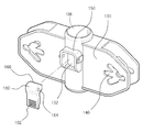
Figure 2 shows the laundry drying rack of the present invention, a partial exploded perspective view showing a state in which the clothes rack is installed horizontally,
3 is a perspective view showing a support in a state in which the clothes rack is installed vertically of the present invention;
4 is a perspective view showing the inner surface of the support of the present invention,
5 is a perspective view showing the height adjusting means of the laundry dryer according to the present invention;
Figure 6 is a perspective view showing a locking member of the laundry drying rack of the present invention,
7 and 8 are views showing a method of using the height adjusting means of the laundry dryer according to the present invention, Figure 7 is a perspective view showing a state capable of height adjustment, Figure 8 is a perspective view showing that the height of the column is fixed.
이하, 첨부도면을 참조하여 본 발명에 대하여 설명하기로 한다.Hereinafter, the present invention will be described with reference to the accompanying drawings.
도 2는 본 고안의 빨래 건조대를 도시한 것으로, 빨래 걸이대를 수평으로 설치한 상태를 도시한 부분 분해사시도이고, 도 3은 본 고안의 빨래 걸이대를 수직으로 설치한 상태의 지지대를 도시한 사시도이고, 도 4는 본 고안의 지지대의 내측면을 나타내는 사시도이다. 2 is a view illustrating a laundry drying rack according to the present invention, which is a partially exploded perspective view showing a state in which a clothes rack is installed horizontally, and FIG. 3 is a perspective view showing a support in a state in which the clothes rack is vertically installed. 4 is a perspective view showing the inner surface of the support of the present invention.
이에 도시한 바와 같이, 본 고안의 빨래 건조대(100)는 빨래를 널기 위한 복수개의 빨래 걸이봉(122)이 구비된 걸이대(120)와, 상기 걸이대(120)가 양측으로 설치되는 지지대를 포함한다.As shown in the drawing, the
상기 지지대는 상기 걸이대(120)를 수평, 상향 또는 하향 경사지게 고정하기 위한 각도 조절공(140)이 형성된 각도 조절부(130)와, 상기 걸이대(120)를 소정 높이로 설치하기 위한 기둥(110)이 삽입되는 원통부(138)로 이루어진다. The support is an
상기 기둥(110)은 베란다나 다용도실 등의 지면에 본 고안의 빨래 건조대(100)를 설치하기 위한 것으로, 상기 기둥(110)의 하부구조는 본 고안에서 한정하는 바가 아니며, 다양하게 적용될 수 있음은 물론이다. The
상기 걸이대(120)에는 상기 각도 조절공(140)에 결합되는 결합돌기(124)가 형성되어 상기 결합돌기(124)와 상기 각도 조절공(140)의 결합에 의해 상기 각도 조절부(130)와 걸이대(120)가 결합되는 것이다. The
상기 각도 조절공(140)은 그 형상에 의해 상기 걸이대(120)를 소정의 각도, 즉, 수평, 수직, 상향 경사, 하향 경사의 4개의 위치로 고정시키는 것으로, 도 3에서 보는 바와 같이, 수평방향으로 소정길이 형성되는 수평부(142)를 중심으로, 상기 걸이대(120)를 상향 경사지게 위치시키기 위한 상향 경사 체결부(146)와, 상기 걸이대(120)를 하향 경사지게 위치시키기 위한 하향 경사 체결부(148)가 대칭방향으로 형성된다.The
한편, 도 4는 본 고안의 각도 조절부의 내측면을 나타내는 사시도로서, 상기 걸이대(120)의 일단부에는 상기 각도 조절부(130)의 내측에 고정되어 상기 걸이대(120)를 지지하기 위한 각도 고정부재(126)가 구비되고, 상기 각도 조절부(130)의 내측면에는 상기 각도 고정부재(126)를 지지하기 위한 복수개의 지지 플렌지(134)와, 상기 각도 고정부재(126)의 이동 시 상기 각도 고정부재(126)를 가이드하는 가이드부(136)가 형성된다. On the other hand, Figure 4 is a perspective view showing the inner surface of the angle adjustment unit of the present invention, the end of the
상기 각도 고정부재(126)는 상기 걸이대(120)의 일단부에 길이방향으로 연장형성된 것으로, 상기 걸이대(120)와 평행한 방향으로 소정길이를 갖는 부재이다.The
또한, 상기 각도 고정부재(126)의 단부에는 상하에 경사면(126a)이 형성된다. In addition, the
상기 지지 플렌지(134)는 상기 각도 조절부(130)의 내측면에서 수평 방향으로 돌출형성되는 것으로, 도 4에서 보는 바와 같이, 상기 각도 조절부(130)의 상단과 하단에 각각 형성되고, 중앙에 2개가 형성된다. The
상기 중앙에 형성된 2개의 지지 플렌지(134)는 상기 각도 고정부재(126)와 동일한 폭으로 형성되어 상기 각도 고정부재(126)가 그 사이에 끼워질 수 있게 된다.The two
이와 같은 구조를 갖는 각도 조절부(130)는 상기 결합돌기(124)가 각도 조절공(140)의 수평부(142)의 일단 또는 타단, 상향 경사 체결부(146), 하향 경사 체결부(148)에 결합함과 동시에 상기 각도 고정부재(126)가 지지 플렌지(134)에 지지되면서 상기 걸이대(120)를 수평, 수직, 상향 경사 또는 하향 경사지게 설치할 수 있다. The
먼저, 수평으로 걸이대(120)를 설치하는 경우를 살펴보면, 도 2의 확대도에 도시한 바와 같이, 각도 조절공(140)의 수평부의 일단, 즉, 상기 원통부(138) 쪽의 일단에 상기 결합돌기(124)가 결합되어 걸이대(120)를 수평으로 위치시킨다. First, looking at the case of installing the
이 경우, 상기 각도 조절부(130)의 내부에서는 도 4에서 보는 바와 같이, 상기 각도 고정부재(126)가 중앙에 형성된 2개의 지지 플렌지(134) 사이에 끼워지게 되어 고정됨으로써, 상기 걸이대(120)를 수평방향으로 설치할 수 있게 된다.In this case, as shown in FIG. 4, the
한편, 상기 걸이대(120)를 수직으로 접는 경우를 살펴보면, 도 3에서 보는 바와 같이, 상기 결합돌기(124)를 밀어 상기 수평부(142)의 타단에 형성된 수직 체결부(144)에 끼우면, 상기 각도 고정부재(126)가 지지 플렌지(134)에서 해제되어 상기 걸이대(120)를 수직방향으로 접을 수 있게 된다. On the other hand, looking at the case of folding the
또한, 상기 걸이대(120)를 상향 경사지게 위치시킬 때에는 상기 결합돌기(124)를 각도 조절공(140)의 상향 경사 체결부(146) 쪽으로 밀어넣어 체결시키는데, 이때 상기 각도 고정부재(126)는 상기 가이드부(136)에 가이드되면서 삽입된다.In addition, when the
이후 도 4에 도시한 바와 같이, 각도 고정부재(126)의 경사면(126a)이 각도 조절부(130)의 하단에 형성된 지지 플렌지(134)에 접하면서 지지력을 받게 되고, 이와 동시에 상기 걸이대(120)의 일단부 모서리가 중앙에 형성된 지지 플렌지(134)에 접하면서 지지력을 받게 되어 상기 걸이대(120)가 상향 경사지게 설치될 수 있는 것이다.4, the
이와는 반대로, 상기 걸이대(120)를 하향 경사지게 설치하기 위해서는 상기 결합돌기(124)를 각도 조절공(140)의 상향 경사 체결부(146) 쪽으로 밀어넣어 체결시키는데, 이때 상기 각도 고정부재(126)는 각도 조절부(130)의 상측에 형성된 가이드부에 가이드되면서 삽입되고, 상기 각도 고정부재(126)가 각도 조절부(130)의 상단에 형성된 지지 플렌지(134)에 접하면서 지지력을 받게 되고, 이와 동시에 상기 걸이대(120)의 일단부 모서리가 중앙에 형성된 지지 플렌지(134)에 접하면서 지지력을 받게 되어 상기 걸이대(120)가 하향 경사지게 설치될 수 있는 것이다.On the contrary, in order to install the
한편, 본 고안의 빨래 건조대는 걸이대(120)의 설치높이를 조절하는 높이조절수단이 더 구비된다.On the other hand, the laundry drying rack of the present invention is further provided with a height adjusting means for adjusting the installation height of the hanger (120).
상기 높이조절수단은 도 5에서 보는 바와 같이, 상기 원통부(138)에 형성된 높이조절공(132)과, 상기 높이조절공(132)을 에워싸도록 상기 원통부(138)에 설치되는 캡부재(150)와, 상기 캡부재(150)에 힌지고정되어 회동하면서 상기 높이조절공(132)을 통해 상기 기둥(110)을 고정시키거나 해제하는 락킹부재(160)로 이루어진다.As shown in FIG. 5, the height adjusting means includes a
도 6은 본 고안의 빨래 건조대의 락킹부재를 도시한 사시도로서, 상기 락킹부재(160)는 상기 기둥(110)에 접촉하여 기둥(110)을 고정시키는 고정돌기(166)가 내측면에 형성되는데, 상기 고정돌기(166)는 상기 캡부재(150)에 힌지고정되는 축공(164)의 내측면에 형성되어 상기 축공(164)을 중심으로 락킹부재(160)를 회동시키면 상기 고정돌기(166)가 상기 높이조절공(132)을 통해 상기 기둥(110)에 접하게 된다.Figure 6 is a perspective view showing a locking member of the laundry drying rack of the present invention, the
상기 락킹부재(160)의 외측면에는 사용자가 락킹부재(160)를 누르기가 용이하도록 엠보(162)가 형성된다.An
도 7 및 도 8은 본 고안의 빨래 건조대의 높이조절수단의 사용방법을 나타내는 것으로, 도 7은 높이조절이 가능한 상태를 도시한 사시도이고, 도 8은 기둥의 높이가 고정되는 것을 도시한 사시도로서, 본 고안의 빨래 건조대는 상기 락킹부재(160)를 해제시키면 상기 락킹부재(160)가 기둥(110)과 접촉하지 않으므로 기둥(110)이 화살표 방향, 즉, 상하 방향으로 자유롭게 유동할 수 있어서, 걸이대(120)의 설치높이를 사용자가 조절할 수 있게 된다.7 and 8 are views showing a method of using the height adjusting means of the laundry dryer according to the present invention, Figure 7 is a perspective view showing a state capable of height adjustment, Figure 8 is a perspective view showing that the height of the column is fixed The laundry drying rack of the present invention releases the locking
또한, 상기 걸이대(120)를 적당한 높이로 고정하기 위해서는 도 8에서 보는 바와 같이, 상기 락킹부재(160)를 회동시켜 상기 고정돌기(166)가 기둥(110)에 접촉하여 가압할 수 있도록 한다. In addition, in order to fix the
이와 같이 고정된 기둥(110)으로 인해 상기 걸이대(120)의 높이를 고정할 수 있으며, 사용자의 신장에 맞게 빨래 걸이대(120)의 높이를 조절하여 사용할 수 있게 된다.Due to the fixed
100 : 빨래 건조대 110 : 기둥
120 : 걸이대 122 : 빨래 걸이봉
124 : 결합돌기 126 : 각도 고정부재
126a : 경사면 130 : 각도 조절부
132 : 높이조절공 134 : 지지 플렌지
140 : 각도 조절공 142 : 수평부
144 : 수직 체결부 146 : 상향 경사 체결부
148 : 하향 경사 체결부 150 : 캡부재
160 : 락킹 부재 162 : 엠보
164 : 축공 166 : 고정돌기100: drying rack 110: pillar
120: hanger 122: clothes hanger rod
124: engaging projection 126: angle fixing member
126a: inclined surface 130: angle adjustment unit
132: height adjustment hole 134: support flange
140: angle adjustment hole 142: horizontal portion
144: vertical fastening portion 146: upward inclined fastening portion
148: downward inclined fastening portion 150: cap member
160: locking member 162: emboss
164: shaft ball 166: fixed protrusion
Claims (4)
복수개의 빨래 걸이봉이 구비된 걸이대와,
상기 걸이대가 양측에 각각 설치되고, 상기 걸이대를 수평, 상향 또는 하향 경사지게 고정하기 위한 각도 조절공이 형성된 각도 조절부와, 상기 걸이대를 소정 높이로 설치하기 위한 기둥이 삽입되는 원통부로 이루어지는 지지대를 포함하며,
상기 걸이대는 상기 각도 조절공에 결합되는 결합돌기가 형성되고, 상기 걸이대의 일단부에는 상기 각도 조절부의 내측에 고정되어 상기 걸이대를 지지하기 위한 각도 고정부재가 구비되고,
상기 각도 조절부의 내측면에는 상기 각도 고정부재를 지지하기 위한 지지 플렌지가 복수개 수평방향으로 형성되고, 상기 각도 고정부재의 이동 시 상기 각도 고정부재를 가이드하는 가이드부가 형성되는 것을 특징으로 하는 빨래 건조대.In the clothes dryer,
Hanger rack with a plurality of clothes hanger rods,
Each of the hangers is installed on both sides, and includes a support including an angle adjusting portion formed with an angle adjusting hole for fixing the hanger horizontally, upwardly or downwardly, and a cylindrical portion into which a column for installing the hanger is installed at a predetermined height. ,
The hanger is formed with a coupling protrusion coupled to the angle adjusting hole, the end of the hanger is fixed to the inside of the angle adjusting portion is provided with an angle fixing member for supporting the hanger,
A plurality of support flanges for supporting the angle fixing member are formed in a horizontal direction on the inner side of the angle adjusting unit, and a guide part for guiding the angle fixing member when the angle fixing member is moved is formed.
상기 각도 조절공은 수평방향으로 소정길이 형성되는 수평부를 중심으로, 상기 걸이대를 상향 경사지게 위치시키기 위한 상향 경사 체결부와, 상기 걸이대를 하향 경사지게 위치시키기 위한 하향 경사 체결부가 대칭방향으로 형성되는 것을 특징으로 하는 빨래 건조대.The method of claim 1,
The angle adjusting hole has an upward inclined fastening portion for positioning the hanger upwardly inclined and a downward inclined fastening portion for positioning the hanger downwardly inclined with respect to a horizontal portion having a predetermined length in a horizontal direction. Washing rack made with.
상기 각도 고정부재의 단부에는 상하에 경사면이 형성되는 것을 특징으로 하는 빨래 건조대.The method of claim 1,
Drying rack characterized in that the inclined surface is formed on the end of the angle fixing member up and down.
상기 걸이대의 설치높이를 조절하는 높이조절수단으로서, 상기 원통부에 형성된 높이조절공과, 상기 높이조절공을 에워싸도록 상기 원통부에 설치되는 캡부재와, 상기 캡부재에 힌지고정되어 회동하면서 상기 높이조절공을 통해 상기 기둥을 고정시키거나 해제하도록 상기 기둥에 접촉하여 기둥을 고정시키는 고정돌기가 내측면에 형성되는 락킹부재로 이루어지는 것을 특징으로 하는 빨래 건조대.
The method of claim 1,
The height adjusting means for adjusting the installation height of the hanger, the height adjusting hole formed in the cylindrical portion, the cap member installed in the cylindrical portion to surround the height adjusting hole, and hinged to the cap member is rotated while And a locking member formed on an inner side of the fixing protrusion for fixing the pillar in contact with the pillar to fix or release the pillar through a height adjusting hole.
Priority Applications (1)
| Application Number | Priority Date | Filing Date | Title |
|---|---|---|---|
| KR2020100002544U KR200456736Y1 (en) | 2010-03-12 | 2010-03-12 | Laundry Drying Hanger |
Applications Claiming Priority (1)
| Application Number | Priority Date | Filing Date | Title |
|---|---|---|---|
| KR2020100002544U KR200456736Y1 (en) | 2010-03-12 | 2010-03-12 | Laundry Drying Hanger |
Publications (2)
| Publication Number | Publication Date |
|---|---|
| KR20110008896U KR20110008896U (en) | 2011-09-20 |
| KR200456736Y1 true KR200456736Y1 (en) | 2011-11-17 |
Family
ID=45090337
Family Applications (1)
| Application Number | Title | Priority Date | Filing Date |
|---|---|---|---|
| KR2020100002544U KR200456736Y1 (en) | 2010-03-12 | 2010-03-12 | Laundry Drying Hanger |
Country Status (1)
| Country | Link |
|---|---|
| KR (1) | KR200456736Y1 (en) |
Cited By (1)
| Publication number | Priority date | Publication date | Assignee | Title |
|---|---|---|---|---|
| KR101271320B1 (en) * | 2012-09-07 | 2013-06-04 | 박영자 | Multifunction supporter |
Families Citing this family (1)
| Publication number | Priority date | Publication date | Assignee | Title |
|---|---|---|---|---|
| KR200493980Y1 (en) * | 2020-09-04 | 2021-07-09 | 남미경 | Height adjuster of drying rack |
Citations (1)
| Publication number | Priority date | Publication date | Assignee | Title |
|---|---|---|---|---|
| KR200298834Y1 (en) | 2002-10-02 | 2002-12-28 | 이영철 | A made of rank folding preliminary washing construction a building a structure |
-
2010
- 2010-03-12 KR KR2020100002544U patent/KR200456736Y1/en not_active IP Right Cessation
Patent Citations (1)
| Publication number | Priority date | Publication date | Assignee | Title |
|---|---|---|---|---|
| KR200298834Y1 (en) | 2002-10-02 | 2002-12-28 | 이영철 | A made of rank folding preliminary washing construction a building a structure |
Cited By (1)
| Publication number | Priority date | Publication date | Assignee | Title |
|---|---|---|---|---|
| KR101271320B1 (en) * | 2012-09-07 | 2013-06-04 | 박영자 | Multifunction supporter |
Also Published As
| Publication number | Publication date |
|---|---|
| KR20110008896U (en) | 2011-09-20 |
Similar Documents
| Publication | Publication Date | Title |
|---|---|---|
| KR100953909B1 (en) | Hanger | |
| KR101118088B1 (en) | Laundry hanger | |
| US20110114582A1 (en) | Rotating Clothes Drying Rack | |
| KR200456736Y1 (en) | Laundry Drying Hanger | |
| KR101656215B1 (en) | Clothes for the laundry veranda window sill | |
| KR100694884B1 (en) | Washing dryness | |
| KR101862627B1 (en) | A laundries dry device for the use of veranda | |
| KR20140055573A (en) | A laundries dry device for the use of a veranda | |
| KR101063101B1 (en) | Futon Rack | |
| KR200472428Y1 (en) | Indoor attached folding laundry dryer | |
| KR200461651Y1 (en) | Laundry drying rack | |
| KR20090014836A (en) | Laundry hanger | |
| KR20110007989U (en) | Dry hanger adjustable its slope | |
| KR20070054822A (en) | Apparatus for drying clothing | |
| KR101352341B1 (en) | Foldable Hanger for Laundry | |
| KR101487907B1 (en) | Drying stand with adjustable and extendable construction | |
| CN210425846U (en) | Railing type double-layer drying rack | |
| KR200482242Y1 (en) | Clothes drying hanger | |
| CN210425847U (en) | Railing type drying rack | |
| KR20130003636U (en) | A laundries dry device for the use of a veranda | |
| KR200439022Y1 (en) | Leveling device for clothes rack | |
| JP3168864U (en) | awning | |
| KR101379750B1 (en) | Hanger | |
| JP3784020B2 (en) | Clothes rack | |
| KR200403290Y1 (en) | Stand for dryer the laundry in fold up type |
Legal Events
| Date | Code | Title | Description |
|---|---|---|---|
| A201 | Request for examination | ||
| E701 | Decision to grant or registration of patent right | ||
| REGI | Registration of establishment | ||
| FPAY | Annual fee payment |
Payment date: 20140904 Year of fee payment: 4 |
|
| FPAY | Annual fee payment |
Payment date: 20151228 Year of fee payment: 5 |
|
| FPAY | Annual fee payment |
Payment date: 20160824 Year of fee payment: 6 |
|
| LAPS | Lapse due to unpaid annual fee |