JP2010142430A - Furniture with top plate - Google Patents
Furniture with top plate Download PDFInfo
- Publication number
- JP2010142430A JP2010142430A JP2008322970A JP2008322970A JP2010142430A JP 2010142430 A JP2010142430 A JP 2010142430A JP 2008322970 A JP2008322970 A JP 2008322970A JP 2008322970 A JP2008322970 A JP 2008322970A JP 2010142430 A JP2010142430 A JP 2010142430A
- Authority
- JP
- Japan
- Prior art keywords
- top plate
- keyboard
- area
- furniture
- arrangement area
- Prior art date
- Legal status (The legal status is an assumption and is not a legal conclusion. Google has not performed a legal analysis and makes no representation as to the accuracy of the status listed.)
- Granted
Links
- 230000000630 rising effect Effects 0.000 claims description 4
- 210000000707 wrist Anatomy 0.000 abstract description 12
- 230000007246 mechanism Effects 0.000 description 31
- 230000000694 effects Effects 0.000 description 2
- 230000003028 elevating effect Effects 0.000 description 1
Images



Landscapes
- Tables And Desks Characterized By Structural Shape (AREA)
Abstract
Description
本発明は、オフィス等において、パソコン等の情報端末を用いた作業及び紙の書類等への記帳作業に好適に用いられる天板付き家具に関する。 TECHNICAL FIELD The present invention relates to furniture with a top plate that is suitably used for work using an information terminal such as a personal computer and bookkeeping work on paper documents in an office or the like.
従来、オフィス等において、パソコン等の情報端末を用いた作業を行う者が好適に使用可能な天板付き家具として、天板に、情報端末のキーボードを載せるための受け台と、この受け台を略水平姿勢に保ちつつ天板の下側の収納する収納位置とこの収納位置から天板の使用端側に引き出した使用位置との間で天板の下面に沿ってスライド可能に支持する支持機構と、前記受け台に載せ置いたキーボードを前記収納位置においては略水平姿勢に維持し、前記使用位置においてはキーボードの後端部を押し上げて前傾姿勢にする押し上げ機構とを具備するものが知られている(例えば、特許文献1を参照)。
ところで、このような天板付き家具の天板上に配置したキーボードを操作する際には、利用者は、手首をキーボードの手前に載置し、手首を上方に折り返してキーボードに触れて操作を行うことになる。このような姿勢でキーボード操作を長時間行う場合に、利用者が腕や手首に疲れを感じる不具合が起こり得る。 By the way, when operating the keyboard arranged on the top plate of such furniture with a top plate, the user places the wrist in front of the keyboard, folds the wrist upward and touches the keyboard. Will do. When the keyboard is operated in such a posture for a long time, a problem that the user feels tired on the arm or wrist may occur.
本発明はこのような課題を解決することを目的とする。 The present invention aims to solve such problems.
すなわち、以上のような課題を解決すべく、本発明に係る天板付き家具は、天板面の一部又は全部を、反使用端側に向けて下降する傾斜を有するとともにキーボードを載せ置くためのキーボード配置領域とすることが少なくとも可能であることを特徴とする。 That is, in order to solve the above problems, the furniture with a top plate according to the present invention has a slope in which part or all of the top plate surface is lowered toward the counter-use end side, and a keyboard is placed thereon. It is at least possible to use the keyboard arrangement area.
このようなものであれば、前記キーボード配置領域にキーボードを配置すると、このキーボード配置領域は反使用端側に向けて下降する傾斜を有するので、キーボード操作を行う際に、手首を上方に折り返す必要がなくなる。なお、「キーボード配置領域とすることが少なくとも可能である」とは、該当する領域が常時反使用端側に向けて下降する傾斜を有する状態をとるものだけでなく、該当する領域を反使用端側に向けて下降する傾斜を有する状態に変化させることが可能であるものをも含む概念である。 In such a case, when the keyboard is arranged in the keyboard arrangement area, the keyboard arrangement area has a slope that descends toward the opposite end, so that it is necessary to fold the wrist upward when performing keyboard operation. Disappears. Note that “at least possible to be a keyboard layout area” means not only that the corresponding area has a state in which the corresponding area is always inclined downward toward the counter-use end side, but also the corresponding area is the counter-use end. It is a concept including what can be changed to a state having an inclination that descends toward the side.
キーボード操作を行う際の手首の上方への折り返しをより効果的に抑制するには、前記キーボード配置領域を前記天板面の他の領域よりも下方に位置させるべく、前記キーボード配置領域と前記天板面の他の領域との間に段差を設けているものが望ましい。このようなものであれば、キーボード配置領域にキーボードを載せ置いた場合の該キーボードの上面の高さ位置が、前記天板面の他の領域にキーボードを載せ置いた場合の上面の高さ位置よりも前記段差分だけ下方になるからである。 In order to more effectively suppress the upward folding of the wrist when the keyboard is operated, the keyboard placement area and the ceiling are arranged so that the keyboard placement area is positioned below the other areas of the top plate surface. What provided the level | step difference between the other area | regions of a board surface is desirable. If this is the case, the height position of the upper surface of the keyboard when the keyboard is placed on the keyboard placement area is the height position of the upper surface when the keyboard is placed on another area of the top plate surface. This is because it is lower than the step.
キーボード操作の他にマウス操作を行う場合に、マウスを安定して天板上に載せ置いておけるようにするためには、前記天板の一部を前記キーボード配置領域としているものであって、前記キーボード配置領域の側方に、このキーボード配置領域よりも傾斜が緩やかなマウス配置領域を設けているものが望ましい。このようなものであれば、マウス配置領域にマウスを配置すれば、マウスが天板からずり落ちる不具合が起こりにくいからである。 When performing a mouse operation in addition to the keyboard operation, in order to stably place the mouse on the top board, a part of the top board is used as the keyboard arrangement area, It is desirable to provide a mouse arrangement area with a gentler slope than the keyboard arrangement area on the side of the keyboard arrangement area. In such a case, if the mouse is placed in the mouse placement area, it is difficult for the mouse to slide down from the top board.
利用者の腕の疲れをさらに軽減するには、前記キーボード配置領域の両側端部の前方に、このキーボード配置領域よりも傾斜が緩やかであるとともに利用者の腕を載せ置くことが可能な腕支持領域を前方に突出させて設けているものが望ましい。このようなものであれば、肘当てを有しない椅子とともに用いる場合であっても、利用者の腕を腕支持領域に載せておくことができるからである。さらに、腕の短い利用者がこの天板付き家具を利用する場合、利用者の胴体を腕支持領域間の部位に配置し、腕を伸ばすことなくキーボード操作を行うことができる。 In order to further reduce the fatigue of the user's arm, the arm support has a gentler slope than that of the keyboard placement area and can be placed on the front of the both sides of the keyboard placement area. What has provided the area | region protruded ahead is desirable. This is because the user's arm can be placed on the arm support area even when used with a chair without an armrest. Furthermore, when a user with short arms uses the furniture with a top board, the user's torso can be arranged at a position between the arm support areas, and the keyboard can be operated without extending the arms.
利用者の好みに応じた使用態様を選択できるようにするには、前記キーボード配置領域の傾斜を変更可能であるものが望ましい。 In order to be able to select a usage mode according to the user's preference, it is desirable that the inclination of the keyboard layout area can be changed.
さらに、このような天板付き家具を利用してパソコン等の情報端末を用いた作業及び紙による書類への筆記作業の双方を快適に行えるようにするには、前記キーボード配置領域を有する第1の天板と、この第1の天板の上方に配してなる第2の天板を具備し、前記第2の天板の一部又は全部を、反使用端側を上昇傾斜させる記帳領域としているものが望ましい。このようなものであれば、紙による書類の反使用端側の位置に筆記を行う場合に、従来の水平な天板上の書類上に筆記する場合と比較して、頭頸部を前傾させることや、腕を大きく伸ばす必要がなくなるからである。また、天板面の一部又は全部を、反使用端側に向けて上昇する傾斜を有する記帳領域とすることが少なくとも可能であるものであっても、同様の効果が得られる。 Furthermore, in order to be able to comfortably perform both work using an information terminal such as a personal computer and writing work on a paper document using such furniture with a top plate, the first keyboard having the keyboard arrangement area is provided. And a second top plate disposed above the first top plate, and a part or the whole of the second top plate is a recording area in which the counter-use end side is inclined upward. Is desirable. If this is the case, when writing on the opposite side of the paper document, the head and neck will be tilted forward compared to writing on a document on a conventional horizontal top plate. This is because it is not necessary to greatly extend the arm. Moreover, even if it is possible at least to make a part or all of the top plate surface into a bookkeeping area having an inclination rising toward the counter-use end, the same effect can be obtained.
利用者の好みに応じた使用態様を選択できるようにするには、前記記帳領域の傾斜を変更可能であるものが望ましい。 In order to be able to select a usage mode according to the user's preference, it is desirable that the inclination of the bookkeeping area can be changed.
本発明に係る天板付き家具の構成によれば、天板の一部又は全部を反使用端側に向けて下降する傾斜を有するキーボード配置領域とすることが少なくとも可能であるので、このようなキーボード配置領域に配置したキーボード操作を行う際に、手首を上方に折り返す必要がなくなり、従って、利用者が腕や手首に疲れを感じる不具合の発生を抑制できる。 According to the configuration of the furniture with a top plate according to the present invention, at least part of the top plate can be a keyboard placement region having a slope that descends toward the counter-use end side. When the keyboard arranged in the keyboard arrangement area is operated, it is not necessary to fold the wrist upward. Therefore, it is possible to suppress the occurrence of the problem that the user feels tired on the arm or wrist.
以下、本発明の一実施形態について述べる。 Hereinafter, an embodiment of the present invention will be described.
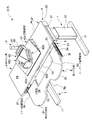
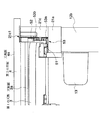
本実施形態に係る天板付き家具たる机Dは、図1〜図8に示すように、床面から起立して設けた脚1と、この脚1に支持させてなる天板支持構造体2と、この天板支持構造体2に支持させてなる第1の天板3と、この第1の天板3より上方に配してなり前記天板支持構造体2に同じく支持させてなる第2の天板4と、これら第1及び第2の天板3、4を相反的に前後方向に移動させる天板移動機構5とを具備する。また、この机Dには、前記天板支持構造体2に取り付けてなる支持部61と、この支持部61に高さ方向位置を変更可能に一端部を支持させてなるアーム本体62とを有するディスプレイアーム6を取り付け可能である。
As shown in FIGS. 1 to 8, the desk D, which is a furniture with a top plate according to the present embodiment, has a
具体的には、前記脚1は、前記図1〜図4に示すように、左右1対に設けていて、前後方向に延伸するベース11と、このベース11から起立する伸縮可能な脚支柱12と、この脚支柱12を駆動する駆動装置13とを具備する。前記脚支柱12は、前記ベース11から起立する中空の固定脚要素12aと、この固定脚要素12aにテレスコープ状に嵌め合わせてなり上下方向に移動可能な可動脚要素12bとを有する。この可動脚要素12bに、前記駆動装置13を取り付けていて、この駆動装置13からの駆動力を受けて可動脚要素12bが固定脚要素12aにたいして嵌め合い度合いを変更しつつ昇降するようにしている。そして、この可動脚要素12bの上端部に、前記天板支持構造体2を取り付けるようにしている。
Specifically, as shown in FIGS. 1 to 4, the
前記天板支持構造体2は、前記図1〜図3、図7、及び図8に示すように、前記脚1の上端部、より具体的には前記の可動脚要素12bの上端部にそれぞれ取り付けてなる側枠21と、これら側枠21の後端部同士を接続する背枠22とを具備する。前記側枠21は、前記昇降脚1の外側部の上方に取り付けてなる側枠本体21aと、この側枠本体21aの内方に設けてなる第1の天板支持部21bと、前記側枠本体21aの外側端部の上方に設けてなる第2の天板支持部21cとを具備する。なお、前記図7では、第2の天板支持部21cは省略して示している。前記第1の天板支持部21bの内側面には、第1のスライドレール21b1を設けている。この第1のスライドレール21b1は、前記側枠21に取り付けてなる図示しないアウターレールと、このアウターレールに案内されつつ前後動可能な中間レール21b3と、この中間レール21b3にさらに案内されつつ前後動可能であるとともに、前記第1の天板3に取り付けてなるインナーレール21b4とを有し、このインナーレール21b4により第1の天板3を前後方向に移動可能に支持している。また、前記第2の天板支持部21cの内側面には、第2のスライドレール21c1を設けている。この第2のスライドレール21c1も、図示はしないが、前記側枠21に取り付けてなるアウターレールと、このアウターレールに案内されつつ前後動可能な中間レールと、この中間レールにさらに案内されつつ前後動可能であるとともに、前記第2の天板4に取り付けてなるインナーレールとを有し、このインナーレールにより第2の天板4を前後方向に移動可能に支持している。すなわち、前記側枠21に設けた第1及び第2のスライドレール21b1、21c1を介して、第1及び第2の天板3、4をそれぞれ前後方向に移動可能に支持している。なお、前記第1及び第2のスライドレール21b1、21c1には、第1及び第2の天板3、4を使用位置Uにそれぞれ保持可能にすべく図示しない節度機構をそれぞれ設けている。
As shown in FIGS. 1 to 3, 7, and 8, the top
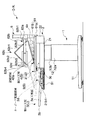
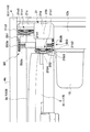
前記第1の天板3は、前記図1、図2、図4、図5、図7、及び図8に示すように、前記天板支持構造体2の第1のスライドレール21b1を介して、使用位置Uと使用位置Uより後方の収納位置Sとの間で移動可能に支持されている。また、この第1の天板3の天板面3a上にはキーボードを配置可能である。さらに詳述すると、この第1の天板3の幅方向中央部の反使用端縁3c寄りの部位には、反使用端縁3c側に向けて下降する傾斜を有するとともにキーボードを載せ置くことが可能なキーボード配置領域3dを形成している。このキーボード配置領域3dの奥行き寸法は、標準的なデスクトップパソコンのキーボードの奥行き寸法に略対応させている。また、本実施形態では、このキーボード配置領域3dの傾斜を10度に設定している。一方、このキーボード配置領域3dの幅寸法は、標準的なデスクトップパソコンのキーボードの幅寸法よりも大きくしていて、このキーボード配置領域3d内においてキーボードの幅方向位置を変更可能にしている。そして、この天板面3aのキーボード配置領域3dは、第1の天板3の天板面3aの他の領域よりも下方に位置している。すなわち、このキーボード配置領域3dと前記天板面3aの他の領域との間には段差を設けていて、このキーボード配置領域3dにキーボードを載せ置いた場合の該キーボードの上面の高さ位置が、前記天板面3aの他の領域にキーボードを載せ置いた場合の上面の高さ位置よりも前記段差分だけ下方になるようにしている。一方、この天板面3aのキーボード配置領域3dの左右両側方には、このキーボード配置領域3dよりも傾斜が緩やかなマウス配置領域3eを設けている。さらに、前記キーボード配置領域3dの両側端部の前方には、このキーボード配置領域3dよりも傾斜が緩やかであるとともに利用者の腕を載せ置くことが可能な腕支持領域3fを前方に突出させて設けている。本実施形態では、この天板3のキーボード配置領域3d以外の天板面3aの傾斜を3度に設定している。また、左右の腕支持領域3f間の部位は、利用者の胴体を収納可能な凹部3gとしている。なお、この第1の天板3の床面からの高さ位置は、前記脚支柱12を伸縮させて前記天板支持構造体2を昇降させることにより、450mm〜750mmの範囲で変更可能である。なお、前記第1の天板3の床面からの高さ位置の下限480mmは、日本人成人女性のうち身長が低い方から5%にあたる体格の者が快適にキーボード操作を行える高さ位置として実験により決定したものである。一方、前記第1の天板3の床面からの高さ位置の下限745mmは、日本人成人男性のうち身長が高い方から5%にあたる体格の者が快適にキーボード操作を行える高さ位置として実験により決定したものである。さらに、前記腕支持領域3fの奥行き寸法は、日本人成人男性のうち身長が高い方から5%にあたる体格の者がキーボード操作を行う際に腕のほとんどを載せ置ける寸法として実験により決定したものである。一方、前記凹部3gの奥行き寸法は、日本人成人女性のうち身長が低い方から5%にあたる体格の者が胴体をこの凹部3gに配置した状態でキーボード操作を行うことができる寸法として実験により決定したものである。そして、この第1の天板3より上方に、前記第2の天板4を設けている。
As shown in FIG. 1, FIG. 2, FIG. 4, FIG. 5, FIG. 7, and FIG. 8, the first
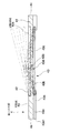
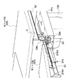
前記第2の天板4は、前記図1、図2、図4、及び図6〜8に示すように、前記天板支持構造体2の第2のスライドレール21c1を介して、使用位置Uと使用位置Uより後方の収納位置Sとの間で移動可能に支持されている。また、この第2の天板4の天板面3a上では、筆記作業を行うことが可能である。さらに詳述すると、この第2の天板4は、略水平な板状の天板本体41と、この天板本体41の所定箇所に幅方向に延伸する軸に支持され自由端側が上下移動可能な筆記台42と、この筆記台42の自由端側の上下方向位置を変更可能にすべく前記天板本体41と筆記台42との間に設けてなる筆記台昇降装置たる筆記台昇降リンク機構43とを具備する。本実施形態では、前記筆記台42の上面を記帳領域42aとし、前記筆記台昇降リンク機構43に対して操作を加えることにより、この記帳領域42aに使用端縁4b側から反使用端縁4c側に向けて上昇する傾斜を設けることが可能である。なお、この第2の天板4の床面からの高さ位置は、前記脚支柱12を伸縮させて前記天板支持構造体2を昇降させることにより変更可能である。その際、この第2の天板4の前記第1の天板3に対する高さ位置は維持される。前記筆記台昇降リンク機構43は、この第2の天板4の使用端縁4bに操作端43a1を臨ませてなり第2の天板4の奥行き方向に延伸する操作レバー43aと、この操作レバー43aの他端部に一端部を接続している第1のリンクメンバ43bと、第2の天板4の反使用端縁4c近傍に一端部を接続している第2のリンクメンバ43cと、これら第1及び第2のリンクメンバ43b、43cの他端部を回転動作可能に接続するとともに前記筆記台42の反使用端縁4c側の部位の下面に設けたストッパ部材42bと係り合いこの筆記台42を支持する支持軸部材43dとを具備する。ここで、本実施形態では、前記ストッパ部材42bは、前記記帳領域42aの傾斜が5度、10度、及び15度となる位置にそれぞれ支持軸部材を係り合わせてなる凹部を有する。また、前記操作レバー43aは、ガイド部材43eにより移動方向をガイドさせている。そして、この第2の天板4は、前記天板移動機構5を介して第1の天板3に接続され、この第1の天板3と相反的に前後移動する。
As shown in FIGS. 1, 2, 4, and 6 to 8, the second
前記天板移動機構5は、前記図1、図2、図7、及び図8に示すように、本実施形態では、前記第1の天板3に設けた第1のラックギア51と、前記第2の天板4に設けた第2のラックギア52と、これら第1及び第2のラックギア51、52に同時に噛み合うピニオンギア53とを備えている。詳述すると、前記第1のラックギア51は、前記第1の天板3の下面に左右1対に取り付けてなり、下面にラック歯を形成してなる。前記第2のラックギア52は、前記第2の天板4の下面に左右1対に取り付けてなり、下面にラック歯を形成してなる。なお、この第2のラックギアは、前記第1のラックギアよりも外方に設けている。そして、前記ピニオンギア53は、前記第1のラックギア51に噛み合う第1のギア体53aと、前記第1のギア体53a及び前記第2のラックギア52に噛み合う第2のギア体53bとからなる。また、前記第1のギア体53aは、前記第2のギア体53bよりも歯幅を大きくしている。そして、前記第1のラックギア51と前記第2のギア体53bとを歯幅方向に隣接させて配置していて、これら第1のラックギア51及び前記第2のギア体53bを前記第1のギア体53aに同時に噛み合わせてこれらを同期移動可能にしている。
As shown in FIGS. 1, 2, 7, and 8, the top
一方、前記ディスプレイアーム6は、前述したように、また、前記図1〜図4に示すように、前記天板支持構造体2に取り付けてなる支持部61と、この支持部61に高さ方向位置を変更可能に一端部を支持させてなるとともに他端部にディスプレイモニタを前後方向への移動のみを可能に支持させてなるアーム本体62とを有する。
On the other hand, as described above, the
前記支持部61は、前記天板支持部61に接続してなる取付部61aと、この取付部から上方に起立して設けた支柱61bとを備えている。
The
前記アーム本体62は、前記支柱61aに抱着させてなる被支持部62aと、この被支持部62aの前方に接続してなる第1及び第2のリンク機構62b、62cと、これら第1及び第2のリンク機構62b、62cに支持させてなるとともに前方にディスプレイモニタを取り付け可能なモニタ取付部62dとを具備する。
The
前記第1のリンク機構62bは、前記支持部61に支持させてなる第1のリンクメンバ62b1と、この第1のリンクメンバ62b1の左右に鉛直方向に延伸する第1の軸62b5を中心に回転可能に一端部を支持させてなる左右の第2のリンクメンバ62b2と、前記第2のリンクメンバ62b2の他端側に鉛直方向に延伸する第2の軸62b6を中心に回転可能にそれぞれ支持させてなる左右の第3のリンクメンバ62b3と、両端部を前記各第3のリンクメンバ62b3の他端側に鉛直方向に延伸する第3の軸62b7を中心に回転可能にそれぞれ支持させてなるとともにモニタを支持させてなる第4のリンクメンバ62b4とを有する。ここで、本実施形態では、前記第1のリンクメンバ62b1及び前記第3のリンクメンバ62b3は、上下に対をなして設けた棒状部材の組を利用して形成している。一方、前記第2のリンクメンバ62b2及び前記第4のリンクメンバ62b4は、1本の棒状部材を利用して形成しているとともに、隣接するリンクメンバの上下の棒状部材の間に進入可能である。
The
一方、前記第2のリンク機構62cは、前記第1のリンク機構62bの第1のリンクメンバ62b1に水平方向に延伸する図示しない第4の軸を介して支持させてなる第5のリンクメンバ62c1と、前記第4のリンクメンバ62b4に水平方向に延伸する図示しない第5の軸を介して支持させてなるとともに前記第5のリンクメンバ62c1に水平方向に延伸する第6の軸62c3を接続してなる第6のリンクメンバ62c2とを有する。ここで、前記第5及び第6のリンクメンバ62c1、62c2は、板状の部材を利用して形成している。
On the other hand, the
この机Dの各部の作動を以下に述べる。 The operation of each part of the desk D will be described below.
キーボード操作を終了し筆記作業を行う際に、天板移動機構5の各部位は以下のように作動する。第1の天板3を使用位置Uから収納位置Sに押し込む操作が行われると、第1の天板3の下面に設けた第1のラックギア51から前記ピニオンギア53の第1のギア体53aに駆動力が伝達されて第1のギア体53aが回転し、このピニオンギア53の第2のギア体53bが第1のギア体53aと同期して回転する。すると、この第2のギア体53bから第2の天板4の下面に設けた第2のラックギア52に回転力が伝達され、この回転力が第2の天板4を使用位置U側に駆動する駆動力に変換される。一方、第2の天板4を収納位置Sから使用位置Uに引き出す操作が行われると、第2の天板4の下面に設けた第2のラックギア52を介して前記ピニオンギア53の第2のギア体53bに駆動力が伝達されて第2のギア体53bが回転し、このピニオンギア53の第1のギア体53aが第2のギア体53bと同期して回転する。すると、この第1のギア体53aから第1の天板3の下面に設けた第1のラックギア51に回転力が伝達され、この回転力が第1の天板3を収納位置S側に駆動する駆動力に変換される。一方、筆記作業を終了しキーボード操作を行う際に第2の天板4を使用位置Uから収納位置Sに押し込む操作、又は第1の天板3を収納位置Sから使用位置Uに引き出す操作が行われると、前記天板移動機構5の各部位は上述した動作と逆方向に作動する。
When the keyboard operation is finished and the writing operation is performed, each part of the top
また、前記筆記台昇降リンク機構43の操作レバー43aの操作端43a1に操作力を加えられると、この操作レバーにより前記筆記台昇降リンク機構43の第1のリンクメンバ43bの一端部が駆動され、第2のリンクメンバ43cの一端部との距離が変化するので、これら第1及び第2のリンクメンバ43b、43cの他端部に接続した支持軸部材43dは奥行き方向位置を変化させつつ、また前記ストッパ部材42bと接触しつつ昇降移動する。そして、筆記台42の傾斜角を5度、10度、15度のうち所望の傾斜角に設定した後、操作を解除すると、筆記台42のストッパ部材42bの凹部と支持軸部材43dとが係り合い、筆記台42が反使用端縁3c側に向けて所望の角度だけ上昇する状態に保持される。また、筆記台42の上面に設定した前記記帳領域42aが第2の天板4の他の領域の天板面4aと面一となった状態すなわち傾斜が0度である状態で操作を解除すると、筆記台42は天板本体41に支持され、傾斜が0度である状態が維持される。
Further, when an operating force is applied to the operation end 43a1 of the
一方、ディスプレイモニタ又はモニタ取付部62dに前後方向に向かう操作力が加えられると、第1のリンク機構62bは以下のように作動する。まず、モニタ取付部62dに接続された第4のリンクメンバ62b4がつれて前後方向に移動する。この操作力は、第4のリンクメンバ62b4から第3のリンクメンバ62b3へ、また、第3のリンクメンバ62b3から第2のリンクメンバ62b2へ、そして、第2のリンクメンバ62b2から第1のリンクメンバ62b1へと順次伝達される。その一方で、第1のリンクメンバ62b1は支持部61に固定されているので、第2及び第3のリンクメンバ62b3を接続する第2の軸62b6は、第4のリンクメンバ62b4と第1のリンクメンバ62b1との距離が変化したことを受けて、側方に移動する。また、第2のリンク機構62cは以下のように作動する。すなわち、前記第2のリンク機構62cの第5及び第6のリンクメンバ62c1、62c2の下端同士が接近し、第6の軸62c3が上下方向に移動する。
On the other hand, when an operation force directed in the front-rear direction is applied to the display monitor or the
一方、ディスプレイモニタ又はモニタ取付部62dに左右方向に向かう操作力が加えられた場合は、前記第2のリンク機構62cの各構成要素、すなわち、第5のリンクメンバ62c1、第6のリンクメンバ62c2、第4の軸、第5の軸、及び第6の軸62c3により、第1のリンク機構62bの各構成要素の左右への移動が規制され、従って、ディスプレイモニタ及びモニタ取付部62dの左右への移動も規制される。
On the other hand, when an operation force directed in the left-right direction is applied to the display monitor or monitor mounting
本実施形態に係る机Dは、以上に説明したように、第1の天板3の天板面3aに、反使用端縁3cに向かい下降する傾斜を有するとともにキーボードを載せ置くためのキーボード配置領域3dを設定しているので、このキーボード配置領域3dにキーボードを配置すると、手首よりキーボードが下方に位置し、従って、キーボード操作を行う際に、手首を上方に折り返す必要がなくなる。さらに、本実施形態では、このキーボード配置領域3dと前記天板面3aの他の領域との間には段差を設けていて、このキーボード配置領域3dにキーボードを載せ置いた場合の該キーボードの上面の高さ位置が、前記天板面3aの他の領域にキーボードを載せ置いた場合の上面の高さ位置よりも前記段差分だけ下方になるようにしているので、この点からも手首の上方への折り返しの防止ないし抑制を図ることができる。
As described above, the desk D according to the present embodiment has a keyboard arrangement for placing the keyboard on the
また、前記キーボード配置領域3dの側方に、このキーボード配置領域3dよりも傾斜が緩やかなマウス配置領域3eを設けているので、キーボード操作の他にマウス操作を行う場合に、マウス配置領域3eにマウスを配置すれば、マウスがこの第1の天板3からずり落ちる不具合が起こりにくく、マウスを安定して第1の天板3の天板面3a上に載せ置いておくことができる。
Further, since a
さらに、前記キーボード配置領域3dの両側端部の前方に、このキーボード配置領域3dよりも傾斜が緩やかであるとともに利用者の腕を載せ置くことが可能な腕支持領域3fを前方に突出させて設けているので、肘当てを有しない椅子とともに用いる場合であっても、利用者の腕を腕支持領域3fに載せておくことができ、従って、利用者の腕の疲れをさらに軽減することができる。さらに、腕の短い利用者がこの机Dを利用する場合、利用者の胴体を左右の腕支持領域3f、3f間の凹部3g内に配置し、腕を伸ばすことなくキーボード操作を行うこともできる。
Further, an
加えて、前記第1の天板3の上方に配してなる第2の天板4の天板面4aの一部を、反使用端縁4cに向かい上昇する傾斜を有する記帳領域42aとしているので、紙による書類の反使用端縁4c側の位置に筆記を行う場合に、従来の水平な天板上の書類上に筆記する場合と比較して、腕を大きく伸ばす必要がなくなる。従って、このような机Dを利用してパソコン等の情報端末を用いた作業及び紙による書類への筆記作業の双方を快適に行うことができる。
In addition, a part of the
そして、前記記帳領域42aの傾斜を変更可能であるので、利用者の好みに応じた使用態様を選択できる。
Since the inclination of the
なお、本発明は以上に述べた実施形態に限られない。 The present invention is not limited to the embodiment described above.
例えば、利用者の好みに応じた使用態様を選択できるようにすべく、前記キーボード配置領域の傾斜を変更可能にしてもよい。 For example, the inclination of the keyboard arrangement area may be changeable so that a usage mode according to the user's preference can be selected.
また、天板を1つだけ設けるとともに、この天板の天板面の一部をキーボード配置領域とするとともに、他の一部を、反使用端側に向けて上昇する傾斜を有する記帳領域とすることが少なくとも可能であるものであっても、同様の効果が得られる。 In addition, only one top plate is provided, and a part of the top plate surface of the top plate is used as a keyboard placement region, and another part of the top plate surface has a slope that rises toward the counter-use end side, Even if it is possible at least, the same effect can be obtained.
一方、上述した実施形態において、上面を記帳領域とした記帳台を複数設け、複数の記帳領域の傾斜をそれぞれ独立に変更可能にしてもよい。 On the other hand, in the above-described embodiment, a plurality of bookkeeping tables whose upper surface is a bookkeeping region may be provided, and the inclinations of the plurality of bookkeeping regions may be independently changed.
さらに、第2の天板の一部に、反使用端側を常時上昇傾斜させてなる記帳領域を設けるようにしてもよい。この場合、傾斜角は変更可能であってもなくてもよい。 Furthermore, you may make it provide the bookkeeping area | region which always makes a counter-use end side raise and incline in a part of 2nd top plate. In this case, the inclination angle may or may not be changeable.
加えて、肘つき椅子とともに利用することが予めわかっている場合等においては、腕支持領域や、天板の使用端側の凹部は省略してもよい。 In addition, when it is known in advance that it is used together with the chair with the elbow, the arm support region and the concave portion on the use end side of the top plate may be omitted.
さらに、天板の反使用端側を昇降動作可能なものとし、天板の反使用端側を下降させることにより、天板面全体を、反使用端側に向けて下降する傾斜を有するキーボード配置領域に設定できるものであってもよい。このようなものの場合、天板の反使用端側を上昇させることにより、天板面全体を、反使用端側に向けて上昇する傾斜を有する記帳領域に設定できるものであればなおよい。 Furthermore, the keyboard layout has an inclination that allows the counter-use end side of the top plate to be moved up and down, and the entire top plate surface is lowered toward the counter-use end side by lowering the counter-use end side of the top plate. It may be set in the area. In such a case, it is preferable that the entire top plate surface can be set to a bookkeeping area having an inclination rising toward the counter use end side by raising the counter use end side of the top plate.
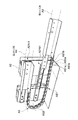
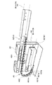
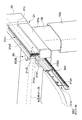
加えて、図9〜図11に示すように、天板支持構造体A2に第1及び第2の天板A3、A4を支持させる構成の机において、一端部を第1の天板A3に接続してなるとともに、他端部を第2の天板A4に接続してなり、一方側にのみ屈曲可能なチェーンA51と、このチェーンA51の後方に設けられこのチェーンの後方への移動を規制する移動規制部A52とを具備する天板移動機構A5を形成してもよい。前記チェーンA51は、複数のチェーン要素A51aを連結軸A51bを介して接続してなり、図9〜図11における内方側にのみ屈曲可能である。一方、前記移動規制部A52は、前方に開口する半円筒状の部材であり、前記第1又は第2の天板A3、A4からチェーンA51に後方に押し込む操作力が伝達された際にチェーンA51の移動方向を案内し、前記操作力が加えられていない側の天板を前方に押し出す操作力に変換する。なお、図示はしないが、この移動規制部A52とチェーンA51を挟んで反対側に、チェーンA51の前方への移動を規制する抜け止め部を、滑車等を利用して設けるようにしてもよい。このような抜け止め部を設けた場合、第1又は第2の天板をのうち一方を収納位置に向けて後方に押し込む操作を加えた場合に他方を使用位置に向けて前方に移動させることができるだけでなく、第1又は第2の天板のうち一方を使用位置に向けて前方に引き出す操作を加えた場合に、他方の天板を収納位置に向けて後方に移動させることができる。 In addition, as shown in FIGS. 9 to 11, in the desk configured to support the first and second top plates A3 and A4 on the top plate support structure A2, one end is connected to the first top plate A3. In addition, the other end is connected to the second top plate A4, and a chain A51 that can be bent only on one side, and provided behind the chain A51, restricts the movement of the chain to the rear. You may form the top plate moving mechanism A5 which comprises the movement control part A52. The chain A51 is formed by connecting a plurality of chain elements A51a via a connecting shaft A51b, and can be bent only inward in FIGS. On the other hand, the movement restricting portion A52 is a semi-cylindrical member that opens to the front, and the chain A51 is transmitted when an operation force for pushing backward from the first or second top plate A3, A4 to the chain A51 is transmitted. The movement direction is guided and converted into an operation force that pushes forward the top plate to which the operation force is not applied. Although not shown, a retaining portion for restricting the forward movement of the chain A51 may be provided on the opposite side of the movement restricting portion A52 and the chain A51 using a pulley or the like. When such a retaining portion is provided, when an operation of pushing one of the first or second top plates backward toward the storage position is performed, the other is moved forward toward the use position. In addition, when an operation of pulling one of the first or second top plates forward toward the use position is added, the other top plate can be moved rearward toward the storage position.
さらに、前述した実施形態に係る天板移動機構5に替えて、以下に述べるような天板移動機構B5を採用してもよい。この天板移動機構B5は、図12及び図13に示すように、前記第1の天板3に設けた第1のラックギアB51と、前記第2の天板4に設けた第2のラックギアB52と、これら第1及び第2のラックギアB51、B52に同時に噛み合うピニオンギアB53とを備えている。詳述すると、前記第1のラックギアB51は、前記第1の天板3の外側面に取り付けてなり、外側面にラック歯を形成してなる。前記第2のラックギアB52は、ブラケットB52aを介して前記第2の天板4の下面に左右1対に取り付けてなり、内側面にラック歯を形成してなる。そして、前記ピニオンギアB53は、本実施形態では、前記第1のラックギアB51に噛み合う第1のギア体B53aと、前記第2のラックギアB52に噛み合う第2のギア体B53bと、これら第1及び第2のギア体B53a、B53bの回動中心をなしこれら第1及び第2のギア体B53a、B53bを接続する軸B53cとからなる。
Furthermore, instead of the top
キーボード操作を終了し筆記作業を行う際に、この天板移動機構B5の各部位は以下のように作動する。第1の天板3を使用位置Uから収納位置Sに押し込む操作が行われると、第1の天板3から第1のラックギアB51を介して前記ピニオンギアB53の第1のギア体B53aに駆動力が伝達され、このピニオンギアB53の第2のギア体B53bが第1のギア体B53aと同期して回転する。すると、この第2のギア体B53bから第2のラックギアB52に回転力が伝達され、この回転力が第2の天板4を使用位置U側に駆動する駆動力に変換される。一方、第2の天板4を収納位置Sから使用位置Uに引き出す操作が行われると、第2の天板4から第2のラックギア52を介して前記ピニオンギアB53の第2のギア体B53bに駆動力が伝達され、このピニオンギアB53の第1のギア体B53aが第2のギア体B53bと同期して回転する。すると、この第1のギア体B53aから第1のラックギアB51に回転力が伝達され、この回転力が第1の天板3を収納位置S側に駆動する駆動力に変換される。一方、筆記作業を終了しキーボード操作を行う際に第2の天板4を使用位置Uから収納位置Sに押し込む操作、又は第1の天板3を収納位置Sから使用位置Uに引き出す操作が行われると、前記天板移動機構B5の各部位は上述した動作と逆方向に作動する。
When the keyboard operation is finished and the writing operation is performed, each part of the top board moving mechanism B5 operates as follows. When an operation of pushing the first
そして、上述した実施形態では、リンク機構43を利用して筆記台昇降装置を形成しているが、ガススプリング等、他の手段を利用して筆記台昇降装置を形成してもよい。
In the above-described embodiment, the writing table lifting device is formed using the
その他、机だけでなくパソコン収納ラックを同様に構成する態様や、ディスプレイアームにディスプレイモニタを支持させる代わりに天板支持構造体等にディスプレイモニタを支持させる態様を採用する等、本発明の趣旨を損ねない範囲で種々に変更してよい。 Other aspects such as adopting an aspect in which not only a desk but also a personal computer storage rack are configured in the same manner, and an aspect in which a display monitor is supported by a top support structure instead of a display arm being supported by a display arm, etc. Various changes may be made without departing from the scope.
D…机
3…第1の天板
3a…天板面
3d…キーボード配置領域
3e…マウス配置領域
3f…腕支持領域
4…第2の天板
4a…天板面
42a…記帳領域
D ...
Claims (8)
Priority Applications (1)
| Application Number | Priority Date | Filing Date | Title |
|---|---|---|---|
| JP2008322970A JP5354524B2 (en) | 2008-12-18 | 2008-12-18 | Furniture with a top plate |
Applications Claiming Priority (1)
| Application Number | Priority Date | Filing Date | Title |
|---|---|---|---|
| JP2008322970A JP5354524B2 (en) | 2008-12-18 | 2008-12-18 | Furniture with a top plate |
Publications (2)
| Publication Number | Publication Date |
|---|---|
| JP2010142430A true JP2010142430A (en) | 2010-07-01 |
| JP5354524B2 JP5354524B2 (en) | 2013-11-27 |
Family
ID=42563471
Family Applications (1)
| Application Number | Title | Priority Date | Filing Date |
|---|---|---|---|
| JP2008322970A Expired - Fee Related JP5354524B2 (en) | 2008-12-18 | 2008-12-18 | Furniture with a top plate |
Country Status (1)
| Country | Link |
|---|---|
| JP (1) | JP5354524B2 (en) |
Citations (2)
| Publication number | Priority date | Publication date | Assignee | Title |
|---|---|---|---|---|
| JPH0520633U (en) * | 1991-09-03 | 1993-03-19 | 住友電気工業株式会社 | Office machine desk |
| JP2006110068A (en) * | 2004-10-14 | 2006-04-27 | Okamura Corp | Table provided with auxiliary top plate |
-
2008
- 2008-12-18 JP JP2008322970A patent/JP5354524B2/en not_active Expired - Fee Related
Patent Citations (2)
| Publication number | Priority date | Publication date | Assignee | Title |
|---|---|---|---|---|
| JPH0520633U (en) * | 1991-09-03 | 1993-03-19 | 住友電気工業株式会社 | Office machine desk |
| JP2006110068A (en) * | 2004-10-14 | 2006-04-27 | Okamura Corp | Table provided with auxiliary top plate |
Also Published As
| Publication number | Publication date |
|---|---|
| JP5354524B2 (en) | 2013-11-27 |
Similar Documents
| Publication | Publication Date | Title |
|---|---|---|
| JP3198070U (en) | Adjustable tabletop | |
| CN112955053B (en) | Multifunctional tea table | |
| JP2010524633A (en) | Mobile integrated stand-alone workstation | |
| JP2009522680A (en) | A device that supports viewing computer displays | |
| CN104523059B (en) | Multifunctional supporting device for seat | |
| JP2006130048A (en) | Desk with lifting top plate | |
| JP5354524B2 (en) | Furniture with a top plate | |
| JP2010142429A (en) | Furniture with top plate | |
| JP6326090B2 (en) | Lifting shelf | |
| JP2013017707A (en) | Cart device | |
| JP5368012B2 (en) | Delivery table | |
| CN201523809U (en) | Computer desk with adjustable drawer height | |
| JP3642391B2 (en) | Work station | |
| JP2006034469A (en) | Standing auxiliary chair | |
| JP2021533956A (en) | Drive mechanism | |
| JP3669267B2 (en) | Wagon desk with lifting table | |
| CN201403777Y (en) | Convenient computer writing table with drawer connected with double-layer elbow supporting plate | |
| JP5487447B2 (en) | Chair | |
| JP3613455B2 (en) | Teacher | |
| JP2011024690A (en) | Table and implement for holding straight sitting position | |
| CN219629066U (en) | Integrated office desk | |
| CN201153700Y (en) | Computer desk with drawer capable of simultaneously connecting knee plate and mouse board | |
| CN217987100U (en) | Chair capable of having noon break | |
| JP6521655B2 (en) | Lifting mechanism and furniture | |
| JP7601346B2 (en) | Footrest unit and height adjustable desk |
Legal Events
| Date | Code | Title | Description |
|---|---|---|---|
| A621 | Written request for application examination |
Free format text: JAPANESE INTERMEDIATE CODE: A621 Effective date: 20111124 |
|
| A977 | Report on retrieval |
Free format text: JAPANESE INTERMEDIATE CODE: A971007 Effective date: 20130111 |
|
| A131 | Notification of reasons for refusal |
Free format text: JAPANESE INTERMEDIATE CODE: A131 Effective date: 20130122 |
|
| A521 | Request for written amendment filed |
Free format text: JAPANESE INTERMEDIATE CODE: A523 Effective date: 20130325 |
|
| TRDD | Decision of grant or rejection written | ||
| A01 | Written decision to grant a patent or to grant a registration (utility model) |
Free format text: JAPANESE INTERMEDIATE CODE: A01 Effective date: 20130730 |
|
| A61 | First payment of annual fees (during grant procedure) |
Free format text: JAPANESE INTERMEDIATE CODE: A61 Effective date: 20130820 |
|
| R150 | Certificate of patent or registration of utility model |
Ref document number: 5354524 Country of ref document: JP Free format text: JAPANESE INTERMEDIATE CODE: R150 Free format text: JAPANESE INTERMEDIATE CODE: R150 |
|
| S111 | Request for change of ownership or part of ownership |
Free format text: JAPANESE INTERMEDIATE CODE: R313117 |
|
| SZ03 | Written request for cancellation of trust registration |
Free format text: JAPANESE INTERMEDIATE CODE: R313Z03 |
|
| R350 | Written notification of registration of transfer |
Free format text: JAPANESE INTERMEDIATE CODE: R350 |
|
| S111 | Request for change of ownership or part of ownership |
Free format text: JAPANESE INTERMEDIATE CODE: R313115 |
|
| R350 | Written notification of registration of transfer |
Free format text: JAPANESE INTERMEDIATE CODE: R350 |
|
| R250 | Receipt of annual fees |
Free format text: JAPANESE INTERMEDIATE CODE: R250 |
|
| R250 | Receipt of annual fees |
Free format text: JAPANESE INTERMEDIATE CODE: R250 |
|
| R250 | Receipt of annual fees |
Free format text: JAPANESE INTERMEDIATE CODE: R250 |
|
| R250 | Receipt of annual fees |
Free format text: JAPANESE INTERMEDIATE CODE: R250 |
|
| R250 | Receipt of annual fees |
Free format text: JAPANESE INTERMEDIATE CODE: R250 |
|
| R250 | Receipt of annual fees |
Free format text: JAPANESE INTERMEDIATE CODE: R250 |
|
| R250 | Receipt of annual fees |
Free format text: JAPANESE INTERMEDIATE CODE: R250 |
|
| LAPS | Cancellation because of no payment of annual fees |