JP2009522680A - A device that supports viewing computer displays - Google Patents
A device that supports viewing computer displays Download PDFInfo
- Publication number
- JP2009522680A JP2009522680A JP2008549101A JP2008549101A JP2009522680A JP 2009522680 A JP2009522680 A JP 2009522680A JP 2008549101 A JP2008549101 A JP 2008549101A JP 2008549101 A JP2008549101 A JP 2008549101A JP 2009522680 A JP2009522680 A JP 2009522680A
- Authority
- JP
- Japan
- Prior art keywords
- tray
- display
- vertical
- unit
- support
- Prior art date
- Legal status (The legal status is an assumption and is not a legal conclusion. Google has not performed a legal analysis and makes no representation as to the accuracy of the status listed.)
- Pending
Links
Images


Classifications
-
- F—MECHANICAL ENGINEERING; LIGHTING; HEATING; WEAPONS; BLASTING
- F16—ENGINEERING ELEMENTS AND UNITS; GENERAL MEASURES FOR PRODUCING AND MAINTAINING EFFECTIVE FUNCTIONING OF MACHINES OR INSTALLATIONS; THERMAL INSULATION IN GENERAL
- F16M—FRAMES, CASINGS OR BEDS OF ENGINES, MACHINES OR APPARATUS, NOT SPECIFIC TO ENGINES, MACHINES OR APPARATUS PROVIDED FOR ELSEWHERE; STANDS; SUPPORTS
- F16M11/00—Stands or trestles as supports for apparatus or articles placed thereon Stands for scientific apparatus such as gravitational force meters
- F16M11/20—Undercarriages with or without wheels
- F16M11/2007—Undercarriages with or without wheels comprising means allowing pivoting adjustment
- F16M11/2021—Undercarriages with or without wheels comprising means allowing pivoting adjustment around a horizontal axis
-
- A—HUMAN NECESSITIES
- A47—FURNITURE; DOMESTIC ARTICLES OR APPLIANCES; COFFEE MILLS; SPICE MILLS; SUCTION CLEANERS IN GENERAL
- A47B—TABLES; DESKS; OFFICE FURNITURE; CABINETS; DRAWERS; GENERAL DETAILS OF FURNITURE
- A47B21/00—Tables or desks for office equipment, e.g. typewriters, keyboards
-
- F—MECHANICAL ENGINEERING; LIGHTING; HEATING; WEAPONS; BLASTING
- F16—ENGINEERING ELEMENTS AND UNITS; GENERAL MEASURES FOR PRODUCING AND MAINTAINING EFFECTIVE FUNCTIONING OF MACHINES OR INSTALLATIONS; THERMAL INSULATION IN GENERAL
- F16M—FRAMES, CASINGS OR BEDS OF ENGINES, MACHINES OR APPARATUS, NOT SPECIFIC TO ENGINES, MACHINES OR APPARATUS PROVIDED FOR ELSEWHERE; STANDS; SUPPORTS
- F16M11/00—Stands or trestles as supports for apparatus or articles placed thereon Stands for scientific apparatus such as gravitational force meters
- F16M11/02—Heads
- F16M11/04—Means for attachment of apparatus; Means allowing adjustment of the apparatus relatively to the stand
- F16M11/043—Allowing translations
- F16M11/046—Allowing translations adapted to upward-downward translation movement
-
- F—MECHANICAL ENGINEERING; LIGHTING; HEATING; WEAPONS; BLASTING
- F16—ENGINEERING ELEMENTS AND UNITS; GENERAL MEASURES FOR PRODUCING AND MAINTAINING EFFECTIVE FUNCTIONING OF MACHINES OR INSTALLATIONS; THERMAL INSULATION IN GENERAL
- F16M—FRAMES, CASINGS OR BEDS OF ENGINES, MACHINES OR APPARATUS, NOT SPECIFIC TO ENGINES, MACHINES OR APPARATUS PROVIDED FOR ELSEWHERE; STANDS; SUPPORTS
- F16M11/00—Stands or trestles as supports for apparatus or articles placed thereon Stands for scientific apparatus such as gravitational force meters
- F16M11/02—Heads
- F16M11/04—Means for attachment of apparatus; Means allowing adjustment of the apparatus relatively to the stand
- F16M11/06—Means for attachment of apparatus; Means allowing adjustment of the apparatus relatively to the stand allowing pivoting
- F16M11/10—Means for attachment of apparatus; Means allowing adjustment of the apparatus relatively to the stand allowing pivoting around a horizontal axis
-
- F—MECHANICAL ENGINEERING; LIGHTING; HEATING; WEAPONS; BLASTING
- F16—ENGINEERING ELEMENTS AND UNITS; GENERAL MEASURES FOR PRODUCING AND MAINTAINING EFFECTIVE FUNCTIONING OF MACHINES OR INSTALLATIONS; THERMAL INSULATION IN GENERAL
- F16M—FRAMES, CASINGS OR BEDS OF ENGINES, MACHINES OR APPARATUS, NOT SPECIFIC TO ENGINES, MACHINES OR APPARATUS PROVIDED FOR ELSEWHERE; STANDS; SUPPORTS
- F16M11/00—Stands or trestles as supports for apparatus or articles placed thereon Stands for scientific apparatus such as gravitational force meters
- F16M11/02—Heads
- F16M11/18—Heads with mechanism for moving the apparatus relatively to the stand
-
- F—MECHANICAL ENGINEERING; LIGHTING; HEATING; WEAPONS; BLASTING
- F16—ENGINEERING ELEMENTS AND UNITS; GENERAL MEASURES FOR PRODUCING AND MAINTAINING EFFECTIVE FUNCTIONING OF MACHINES OR INSTALLATIONS; THERMAL INSULATION IN GENERAL
- F16M—FRAMES, CASINGS OR BEDS OF ENGINES, MACHINES OR APPARATUS, NOT SPECIFIC TO ENGINES, MACHINES OR APPARATUS PROVIDED FOR ELSEWHERE; STANDS; SUPPORTS
- F16M2200/00—Details of stands or supports
- F16M2200/08—Foot or support base
Abstract
【課題】 コンピュータ用ディスプレイを見る者にとって見やすくする用に、コンピュータ用ディスプレイを搭載するトレイを有するコンピュータのディスプレイを見るのをサポートする装置を提供する。
【解決手段】 本発明のディスプレイ搭載トレイを有するコンピュータ用ディスプレイを見るのをサポートする装置は、(a)最上位位置と最下位位置との間で、前記ディスプレイ搭載トレイの垂直方向の位置を変化させる垂直方向ユニットと、前記垂直方向ユニットは、水平方向ベースに接続され、(b)前記垂直方向ユニットに支持され、閉鎖位置と開放位置との間の複数の回転位置から表示トレイを回転させるトレイ回転ユニットとを有する。
【選択図】 図1
PROBLEM TO BE SOLVED: To provide an apparatus for supporting viewing of a computer display having a tray on which the computer display is mounted in order to make the computer display easier to see.
An apparatus for supporting viewing of a computer display having a display mounting tray according to the present invention includes: (a) changing a vertical position of the display mounting tray between an uppermost position and a lowermost position; A vertical unit that is connected to a horizontal base, and (b) a tray that is supported by the vertical unit and that rotates the display tray from a plurality of rotational positions between a closed position and an open position. And a rotation unit.
[Selection] Figure 1
Description
本発明は、コンピュータ・ワーク・ステーションに関し、特に、コンピュータ用ディスプレイを見るのをサポートする安価で快適な装置に関する。 The present invention relates to computer work stations and, more particularly, to an inexpensive and comfortable device that supports viewing a computer display.
近年ますます多くの人にとって、コンピュータで作業する時間が増え、コンピュータ・ディスプレイを見る時間が増えている。これは、仕事上であるいはインターネットのユーザの両方にとってそうである。このような成長する市場のニーズに応えるべく、小型のコンピュータ支持部材あるいはワーク・ステーションを工夫して、コンピュータの前でユーザが作業する場所をより快適に且つ疲れないようにする様々な装置/方法が提案されている。このような支持部材の一例は、特許文献1に開示されている。これらの作業支持部材は、椅子と一体型で、家庭用ではなく、オフィスのプロのユーザ用に主にデザインされている。
特許文献2、3は、ユーザが座るシートと、このシートの前に配置されるディスプレイ搭載トレイとを有するコンピュータ・ワーク・ステーションを開示する。このワーク・ステーションは、第1ベースを有する第1シャーシと、細長いシート・サポート部材と、このシート・サポート部材に沿ってシートをリクライニング位置から直立位置の間で姿勢を変化させる第1の位置変化手段とを有する。このワーク・ステーションは、さらに第2ベースを有する第2シャーシと、細長いモニタ支持部材と、このモニタ支持部材の位置を最上位位置と最下位位置との間で変化させる第2の位置変化手段とを有する。結合手段を用いてシートをモニタ支持トレイに結合し、これにより、シートをリクライニング位置に動かすことにより、モニタ支持トレイは最上位位置に動く。シートを垂直位置の方向に動かすことにより、モニタ支持トレイは最下位位置に動く。 Patent Documents 2 and 3 disclose a computer work station having a seat on which a user sits and a display mounting tray arranged in front of the seat. The work station includes a first chassis having a first base, an elongate seat support member, and a first position change that changes the posture of the seat between a reclining position and an upright position along the seat support member. Means. The work station further includes a second chassis having a second base, an elongated monitor support member, and second position changing means for changing the position of the monitor support member between the uppermost position and the lowermost position. Have Using the coupling means, the sheet is coupled to the monitor support tray, whereby the monitor support tray is moved to the uppermost position by moving the sheet to the reclining position. By moving the sheet in the direction of the vertical position, the monitor support tray moves to the lowest position.
ここに開示されたシートとモニタ支持トレイとの間の機械的結合手段は、ワーク・ステーション全体の支持部材の占有面積が大きくなることに加えて、位置の機械的調整機構に結合される比較的フレキシブルなケーブルとスプリングを有する。 The mechanical coupling means disclosed herein between the sheet and the monitor support tray is relatively coupled to the position mechanical adjustment mechanism, in addition to the increased footprint of the support member throughout the work station. It has a flexible cable and spring.
それ故に、本発明の目的は、コンピュータ・ディスプレイを見る際に、最大のフレキシビリティを与えるために、コンピュータ・ディスプレイと一体となったシートを具備する(あるいは具備せずに使用される)モジュラ型の小型のコンピュータ用ディスプレイを見るのをサポートする装置を提供することである。 Therefore, it is an object of the present invention to be modular with or without a seat integrated with a computer display to provide maximum flexibility when viewing the computer display. It is an object of the present invention to provide a device that supports viewing a small computer display.
本発明によれば、以下の構成を有するディスプレイ搭載トレイを有するコンピュータ用ディスプレイを見るのをサポートする装置が提供できる。即ち、本発明の装置は、(a)最上位位置と最下位位置との間で、前記ディスプレイ搭載トレイの垂直方向の位置を変化させる垂直方向ユニットと、前記垂直方向ユニットは水平方向ベースに接続され、(b)前記垂直方向ユニットに支持され、閉鎖位置と開放位置との間の複数の回転位置から表示トレイを回転させるトレイ回転ユニットとを有する。 ADVANTAGE OF THE INVENTION According to this invention, the apparatus which supports seeing the display for computers which has the display mounting tray which has the following structures can be provided. That is, the apparatus of the present invention includes: (a) a vertical unit that changes a vertical position of the display mounting tray between the uppermost position and the lowermost position; and the vertical unit is connected to a horizontal base. And (b) a tray rotation unit that is supported by the vertical unit and rotates the display tray from a plurality of rotation positions between a closed position and an open position.
本発明の前記垂直方向ユニットは、ディスプレイ搭載トレイをスライド可能に支持する一対の平行な弓形レールを有し、第1位置決め装置が、垂直方向位置と回転位置を変化させる。本発明の第1位置決め装置は、モータと機械的リンク機構とを有する。 The vertical unit of the present invention has a pair of parallel arcuate rails that slidably support the display mounting tray, and the first positioning device changes the vertical position and the rotational position. The first positioning device of the present invention has a motor and a mechanical link mechanism.
本発明によれば、以下の構成を有するディスプレイ搭載トレイを有するコンピュータ用ディスプレイを見るのをサポートする装置が提供できる。即ち、本発明の装置は、(a)支持脚部を有し、最上位位置と最下位位置との間で、前記ディスプレイ搭載トレイの垂直方向の位置を変化させる垂直方向ユニットと、前記垂直方向ユニットは水平方向ベースに接続され、(b)前記垂直方向ユニットに支持され、閉鎖位置と開放位置との間の複数の回転位置から表示トレイを回転させるトレイ回転ユニットと、(c)第2シャーシ支持脚部と複数の細長い支持部材とを有し、前記垂直方向支持を安定させる第2シャーシ・ユニットと、(d)前記垂直方向ユニットに回転可能に接続される部材により支持されるデータ入力機器用トレイと、前記部材は、最上位方向と最下位方向の間の回転を変化させるを有する。 ADVANTAGE OF THE INVENTION According to this invention, the apparatus which supports seeing the display for computers which has the display mounting tray which has the following structures can be provided. That is, the apparatus of the present invention includes (a) a vertical unit that has support legs and changes the vertical position of the display mounting tray between the uppermost position and the lowermost position; and the vertical direction A unit connected to a horizontal base; (b) a tray rotating unit supported by the vertical unit and rotating a display tray from a plurality of rotating positions between a closed position and an open position; and (c) a second chassis. A second chassis unit having a support leg and a plurality of elongated support members and stabilizing the vertical support; and (d) a data input device supported by a member rotatably connected to the vertical unit. The tray and the member have changing rotation between the uppermost direction and the lowermost direction.
本発明の垂直方向ユニットは、ディスプレイ搭載トレイをスライド可能に支持する一対の平行な弓形レールを有し、第1位置決め装置が、垂直方向位置と回転位置を変化させ保持する。本発明の部材は、第2位置決めユニットにより回転する。本発明の複数の細長い支持部材は、平行な弓形レールの第2の対と、安定化させる弓形レールとを有し、前記弓形レールの第2の対と安定化させる弓形レールとは、楕円形状を形成するような向きに取り付けられる。 The vertical unit of the present invention has a pair of parallel arcuate rails that slidably support the display mounting tray, and the first positioning device changes and holds the vertical position and the rotational position. The member of the present invention is rotated by the second positioning unit. The plurality of elongated support members of the present invention includes a second pair of parallel arcuate rails and a stabilizing arcuate rail, the arcuate rails stabilizing with the second pair of arcuate rails. It is attached in such a direction as to form.
本発明の装置は、ディスプレイを見る為のシートを有し、前記シートは、シートバックと肘掛けを有し、前記弓形レールの第2の対と垂直方向支持に面して、スライド可能にサポートされ、前記シートは、垂直方向支持部材に対し、最近位置と最遠位置との間を動き、前記シートバックは、リクライニング位置と直立位置との間を回転する。前記シートの動きを変化させる第3位置決めユニットをさらに有する。各位置決めユニットは、モータと機械的リンク機構とを有する。 The apparatus of the present invention has a seat for viewing the display, the seat having a seat back and an armrest, and slidably supported facing a second pair of the arcuate rails and vertical support. The seat moves between a nearest position and a farthest position with respect to the vertical support member, and the seat back rotates between a reclining position and an upright position. It further has a third positioning unit for changing the movement of the sheet. Each positioning unit has a motor and a mechanical link mechanism.
図1に、本発明の一実施例によるコンピュータ用ディスプレイを(見るのを)サポートする装置10を示す。同図において、ディスプレイ搭載トレイ12は、垂直方向ユニット14に沿って、最上位位置と最下位位置との間をスライドする。垂直方向ユニット14の端部は、水平方向ベース15に結合される。トレイ回転ユニット20(図のディスプレイ搭載トレイ12の裏側にある)は、垂直方向ユニット14により支持され、ディスプレイ搭載トレイ12を、図に示す閉鎖位置から垂直方向ユニット14に直交する開放位置の間を回転させる。垂直方向ユニット14は、一対の平行な弓形レール22を有する。この弓形レール22に沿って、ディスプレイ搭載トレイ12は、スライドする。第1位置決め装置24は、1つあるいは複数個の位置決め用の配置用モータ28と1つあるいは複数個の結合装置29とを有し、弓形レール22の間のクロス部材30に回転可能に搭載される。第1位置決め装置24は、ディスプレイ搭載トレイ12のスライド運動と回転運動を提供する。
FIG. 1 illustrates an
一般的に、コンピュータ・ディスプレイ(図示せず)は、ディスプレイ・トレイに搭載されて、トレイが閉鎖位置にある時に直接見ることができる。公知の搭載用器具(図示せず)は、このためディスプレイのトレイの裏側に配置される。ディスプレイ・トレイが開放位置にあると、コンピュータ・ディスプレイは、開放位置のディスプレイ・トレイ上に配置される。この開放位置の構造により、ラップトップ・コンピュータを配置するのに有益で、座ったり立ったりしながら、心地よい角度で作業ができるようになる。一般的に、コンピュータ用ディスプレイを(見るのを)サポートする装置10の水平方向ベース15は、コンピュータ・ディスプレイを見るために快適且つ可変の角度に合うようにデスク(図示せず)表面に搭載されるが、この装置10は、フロア(床)に置くことも可能である。この装置10で、従来の椅子と共に使用し、座りながらディスプレイを見ることもできる。この装置10の別の構成は、弓形レール22を有し、フロア上に配置するのに適したものである。バッテリあるいは電線(図示せず)を用いて、第1位置決め装置24に電力を与えることもできる。コンピュータ・ディスプレイからコンピュータへのワイヤ接続は、弓形レール22に沿って行われ、これによりコンピュータは、この装置10の近傍に配置できるようになる。
Generally, a computer display (not shown) is mounted on the display tray and can be viewed directly when the tray is in the closed position. A known mounting device (not shown) is thus placed behind the display tray. When the display tray is in the open position, the computer display is placed on the display tray in the open position. This open position configuration is useful for placing a laptop computer and allows you to work at a comfortable angle while sitting or standing. Generally, the
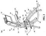
図2において、同図に示す床おき型のコンピュータ用ディスプレイを(見るのを)サポートする装置100は、以下に述べる差異はあるが、図1のコンピュータ用ディスプレイを見るのをサポートする装置10と類似する。そのため同一部品/類似部品は同一番号を付す。マウス用トレイ35は、データ入力機器用トレイ34の端部に取り付けられる。データ入力機器用トレイ34は、入力トレイ支持部材36により支持される。データ入力機器用トレイ34は、キーボード(図示せず)を搭載し、マウスあるいは他のポインティング装置(図示せず)が、マウス用トレイ35上に配置される。
In FIG. 2, the
第2シャーシ・ユニット40は、一対の平行な弓形レール44を有する。この弓形レール44の第1端に弓形レール22が取り付けられ、第2端に脚部46が取り付けられる。垂直方向ユニット14は、伸びた弓形レール22を有し、この弓形レール22は、脚部42となる。少なくとも1個の安定化弓形レール47が、その一端で弓形レール44に取り付けられ、他端で垂直方向ユニット14に取り付けられる。これにより、第2シャーシ・ユニット40の楕円形状が規定される。
The
入力トレイ支持部材36が、弓形レール44の端部の間で第2端に回転可能に連結される。そこで入力トレイ支持部材36は、垂直方向部材に連結されて、データ入力機器用トレイ34の高さ方向の変化が可能となる。入力トレイ支持部材36の動きは、第2位置決めユニット52により制御される。第2位置決めユニット52は、弓形レール44の間に登載され、モータ54と結合装置55を有する。この結合装置55は、モータ54を入力トレイ支持部材36に結合する。
An input
バー48は、弓形レール44、47を連結する。従来の椅子が、第2シャーシ・ユニット40の上に配置されると、コンピュータ・ディスプレイは座った位置で見ることができるようになる。バー48は、フットレスト(足置き)としても機能する。別の構成として、この装置100は、第2シャーシ・ユニット40を立てたり広げたりしながら使用される。
図3において、同図の床おき型のコンピュータ用ディスプレイを(見るのを)サポートする装置100は、図1の装置10と図2の装置100に類似する。従って、同一番号を付した要素は同一動作をする。コンピュータ作業者のシート70は、ヘッドレスト71と、シートバック(背もたれ)73と、少なくとも1個の肘掛け76とを有する。シート70は、弓形レール44上を、垂直支持部材24から離れたり近づいたりするために、スライドするよう配置される。さらに、シートバック73は、よりリクライニング位置あるいはより垂直位置になるよう配置される。シート70の弓形レール44に沿った動きとシートバック73の動きは、別々に第3位置決めユニット80により制御される。この第3位置決めユニット80は、シート70の下に配置されている。第3位置決めユニット80は、シートの左下側に配置された制御スイッチ82を有する。弓形レール44に沿ったシートの動きとシートバック73の回転運動が、様々な位置で可能なために、ユーザに快適な座り心地を提供できる。
In FIG. 3, a
床おき型のコンピュータ用ディスプレイを見るのをサポートする装置100は、第1と第2と第3の位置決めユニットが、制御スイッチ82を通して制御されるよう構成される。その結果、シートに座ったコンピュータ作業者は、ディスプレイ搭載トレイ12と、データ入力機器用トレイ34と、ヘッドレスト71(シートバック73を含む)の動きと位置を完全に制御できる。バー48は、ヘッドレスト71にコンピュータ作業者が座った時に、その人にとって快適なフットレストを提供する。
The
コンピュータ用ディスプレイを見るのをサポートする装置10と床おき型のコンピュータ用ディスプレイを見るのをサポートする装置100の管状の構造とモジュラ構造により、支持部材の安価な製造と且つパッケージが可能となり、これにより、コンピュータ用ディスプレイ支持部材は、容易に移したり組み立てたりできる。
The tubular and modular construction of the
以上の説明は、本発明の一実施例に関するもので、この技術分野の当業者であれば、本発明の種々の変形例を考え得るが、それらはいずれも本発明の技術的範囲に包含される。特許請求の範囲の構成要素の後に記載した括弧内の番号は、図面の部品番号に対応し、発明の容易なる理解の為に付したものであり、発明を限定的に解釈するために用いてはならない。また、同一番号でも明細書と特許請求の範囲の部品名は必ずしも同一ではない。これは上記した理由による。 The above description relates to one embodiment of the present invention, and those skilled in the art can consider various modifications of the present invention, all of which are included in the technical scope of the present invention. The The numbers in parentheses described after the constituent elements of the claims correspond to the part numbers in the drawings, are attached for easy understanding of the invention, and are used for limiting the invention. Must not. In addition, the part numbers in the description and the claims are not necessarily the same even with the same number. This is for the reason described above.
10 コンピュータ用ディスプレイを見るのをサポートする装置
12 ディスプレイ搭載トレイ
14 垂直方向ユニット
15 水平方向ベース
20 トレイ回転ユニット
22 弓形レール
24 第1位置決め装置
28 配置用モータ
29 結合装置
30 クロス部材
34 データ入力機器用トレイ
35 マウス用トレイ
36 入力トレイ支持部材
40 第2シャーシ・ユニット
42 脚部
44 弓形レール
46 脚部
47 安定化弓形レール
48 バー
52 第2位置決めユニット
54 モータ
55 結合装置
70 シート
71 ヘッドレスト
73 シートバック
76 肘掛け
80 第3位置決めユニット
82 制御スイッチ
100 床おき型のコンピュータ用ディスプレイを見るのをサポートする装置
DESCRIPTION OF
Claims (10)
(a) 最上位位置と最下位位置との間で、前記ディスプレイ搭載トレイの垂直方向の位置を変化させる垂直方向ユニットと、
前記垂直方向ユニットは、水平方向ベースに接続され、
(b) 前記垂直方向ユニットに支持され、閉鎖位置と開放位置との間の複数の回転位置から表示トレイを回転させるトレイ回転ユニットと
を有する
ことを特徴とするディスプレイを搭載するトレイを有するコンピュータのディスプレイを見るのをサポートする装置。 In an apparatus that supports viewing a computer display having a display-mounted tray,
(A) a vertical unit that changes a vertical position of the display-mounted tray between an uppermost position and a lowermost position;
The vertical unit is connected to a horizontal base;
(B) A computer having a tray on which a display is mounted, comprising: a tray rotating unit that is supported by the vertical unit and rotates a display tray from a plurality of rotation positions between a closed position and an open position. A device that supports viewing the display.
第1位置決め装置が、垂直方向位置と回転位置を変化させる
ことを特徴とする請求項1記載の装置。 The vertical unit has a pair of parallel arcuate rails that slidably support a display mounting tray;
The apparatus according to claim 1, wherein the first positioning device changes a vertical position and a rotational position.
ことを特徴とする請求項1記載の装置。 The apparatus according to claim 1, wherein the first positioning device includes a motor and a mechanical link mechanism.
(a) 支持脚部を有し、最上位位置と最下位位置との間で、前記ディスプレイ搭載トレイの垂直方向の位置を変化させる垂直方向ユニットと、
前記垂直方向ユニットは、水平方向ベースに接続され、
(b) 前記垂直方向ユニットに支持され、閉鎖位置と開放位置との間の複数の回転位置から表示トレイを回転させるトレイ回転ユニットと
(c) 第2シャーシ支持脚部と複数の細長い支持部材とを有し、前記垂直方向支持を安定させる第2シャーシ・ユニットと、
(d) 前記垂直方向ユニットに回転可能に接続される部材により支持されるデータ入力機器用トレイと、
前記部材は、最上位方向と最下位方向の間の回転を変化させる
を有する
ことを特徴とするディスプレイを搭載するトレイを有するコンピュータのディスプレイを見るのをサポートする装置。 In an apparatus that supports viewing a computer display having a display-mounted tray,
(A) a vertical unit having support legs and changing a vertical position of the display mounting tray between an uppermost position and a lowermost position;
The vertical unit is connected to a horizontal base;
(B) a tray rotation unit supported by the vertical unit and rotating the display tray from a plurality of rotation positions between a closed position and an open position; and (c) a second chassis support leg and a plurality of elongated support members. A second chassis unit for stabilizing the vertical support;
(D) a data input device tray supported by a member rotatably connected to the vertical unit;
An apparatus for supporting viewing of a computer display having a tray on which the display is mounted, wherein the member has a rotation change between a top direction and a bottom direction.
第1位置決め装置が、垂直方向位置と回転位置を変化させ保持する
ことを特徴とする請求項4記載の装置。 The vertical unit has a pair of parallel arcuate rails that slidably support a display mounting tray;
The apparatus according to claim 4, wherein the first positioning device changes and holds the vertical position and the rotational position.
ことを特徴とする請求項4記載の装置。 The apparatus according to claim 4, wherein the member is rotated by a second positioning unit.
前記弓形レールの第2の対と安定化させる弓形レールとは、楕円形状を形成するよう方向付けられ、取り付けられる
ことを特徴とする請求項4記載の装置。 The plurality of elongated support members includes a second pair of parallel arcuate rails and a stabilizing arcuate rail;
5. The apparatus of claim 4, wherein the second pair of arcuate rails and the stabilizing arcuate rail are oriented and attached to form an elliptical shape.
前記シートは、シートバックと肘掛けを有し、前記弓形レールの第2の対と垂直方向支持に面して、スライド可能にサポートされ、
前記シートは、垂直方向支持部材に対し、最近位置と最遠位置との間を動き、
前記シートバックは、リクライニング位置と直立位置との間を回転する
ことを特徴とする請求項4記載の装置。 It has a sheet for viewing the display,
The seat has a seat back and an armrest, and is slidably supported facing a second pair of the arcuate rails and vertical support;
The seat moves between the nearest and farthest positions relative to the vertical support member;
The apparatus of claim 4, wherein the seat back rotates between a reclining position and an upright position.
ことを特徴とする請求項8記載の装置。 9. The apparatus according to claim 8, further comprising a third positioning unit that changes movement of the sheet.
ことを特徴とする請求項9記載の装置。
The apparatus of claim 9, wherein each positioning unit includes a motor and a mechanical linkage.
Applications Claiming Priority (1)
| Application Number | Priority Date | Filing Date | Title |
|---|---|---|---|
| PCT/IL2006/000011 WO2007077548A1 (en) | 2006-01-03 | 2006-01-03 | Computer display viewing support |
Publications (1)
| Publication Number | Publication Date |
|---|---|
| JP2009522680A true JP2009522680A (en) | 2009-06-11 |
Family
ID=38227955
Family Applications (1)
| Application Number | Title | Priority Date | Filing Date |
|---|---|---|---|
| JP2008549101A Pending JP2009522680A (en) | 2006-01-03 | 2006-01-03 | A device that supports viewing computer displays |
Country Status (6)
| Country | Link |
|---|---|
| US (1) | US8141949B2 (en) |
| EP (1) | EP1968414A4 (en) |
| JP (1) | JP2009522680A (en) |
| CN (1) | CN101374441B (en) |
| IL (1) | IL192599A (en) |
| WO (1) | WO2007077548A1 (en) |
Families Citing this family (24)
| Publication number | Priority date | Publication date | Assignee | Title |
|---|---|---|---|---|
| CA2801856C (en) * | 2004-10-12 | 2014-12-23 | Altimate Medical, Inc. | Modular standing frame |
| US8123664B2 (en) | 2008-01-22 | 2012-02-28 | Invacare Corp. | Seat |
| JP5231855B2 (en) * | 2008-04-18 | 2013-07-10 | 株式会社東芝 | Display device |
| US8749959B2 (en) * | 2009-09-29 | 2014-06-10 | Nati Brook Ventures, Llc | Modular technology furniture |
| US9074721B2 (en) | 2010-06-09 | 2015-07-07 | Alex Lau | Support system |
| US9316346B2 (en) | 2010-06-09 | 2016-04-19 | Colebrook Bosson Saunders (Products) Limited | Support system |
| USD684982S1 (en) | 2010-08-11 | 2013-06-25 | Colebrook Bosson Saunders (Products) Limited | Display support with indicator window |
| JP5715268B2 (en) * | 2011-02-10 | 2015-05-07 | ビーイー・エアロスペース・インコーポレーテッド | Tablet holder and tablet storage system |
| US9220348B2 (en) * | 2011-11-11 | 2015-12-29 | Rad Laboratories Inc. | Apparatus and method for ergonomic support of human system interaction |
| US8991320B2 (en) * | 2013-01-25 | 2015-03-31 | Sparx Smart Pods Inc. | Workstation having automated and powered height, depth and rotational adjusters |
| US9167894B2 (en) | 2013-01-25 | 2015-10-27 | Sparx Smart Pods Inc. | Workstation having automated and powered height, depth and rotational adjusters |
| EP2967211A4 (en) * | 2013-03-15 | 2016-10-12 | Sv Tool Corp | Ergonomic productivity workstation having coordinated and harmonized movement of head rest, backrest, seat, leg rest, arm rests, monitor support, and work trays through sitting, standing and reclining configurations |
| US9603457B2 (en) | 2013-05-31 | 2017-03-28 | Steelcase Inc. | Lounge assemblies for supporting portable electronics devices |
| WO2015017780A1 (en) * | 2013-08-02 | 2015-02-05 | Multiplatform, LLC | Adjustable stand for televisions and monitors |
| US9637921B1 (en) * | 2014-04-03 | 2017-05-02 | Clifford Bollman | System for assembly of modular workstations using quad-beams and rail-arm-leg modules |
| US9596929B2 (en) * | 2014-11-10 | 2017-03-21 | Eugenia Koulizakis | Portable work support and keyboard/mouse tray and work station and tethered chair |
| TWI573950B (en) * | 2015-10-26 | 2017-03-11 | 緯創資通股份有限公司 | Electronic device and support frame capable of rising automatically and rotating selectively |
| CA3041754A1 (en) | 2015-11-13 | 2017-05-18 | Sparx Smartpods Inc. | Systems and methods for controlling an interactive workstation based on biometric input |
| US9700146B1 (en) * | 2015-12-08 | 2017-07-11 | Neale Emerson | Collapsible video display support system |
| US9694294B1 (en) | 2015-12-31 | 2017-07-04 | Oculus Vr, Llc | Navigation controller for virtual-reality systems |
| US9814304B2 (en) * | 2016-03-28 | 2017-11-14 | Wesnel JEANPHILIPPE | Portable office |
| GB2575080A (en) * | 2018-06-28 | 2020-01-01 | Roto Vr Ltd | Desktop platform |
| USD1015755S1 (en) * | 2021-07-22 | 2024-02-27 | Lg Display Co., Ltd. | Chair with display |
| WO2023033797A1 (en) * | 2021-08-31 | 2023-03-09 | Mark Catan | Ergonomic chairs supporting asymmetric leg configurations |
Citations (5)
| Publication number | Priority date | Publication date | Assignee | Title |
|---|---|---|---|---|
| US4915450A (en) * | 1986-11-25 | 1990-04-10 | Cooper Lloyd G B | Work station system |
| US6135358A (en) * | 1997-10-17 | 2000-10-24 | Mefar S.P.A. | Apparatus for washing the nasal cavities |
| JP2001157945A (en) * | 1999-11-30 | 2001-06-12 | Kawamura Electric Inc | Stand for control panel |
| US6315358B1 (en) * | 1997-07-28 | 2001-11-13 | Eran Baru | Computer work station |
| JP2003241848A (en) * | 2002-02-01 | 2003-08-29 | Eran Baru | Computer workstation kit |
Family Cites Families (14)
| Publication number | Priority date | Publication date | Assignee | Title |
|---|---|---|---|---|
| US4779922A (en) * | 1986-11-25 | 1988-10-25 | Cooper Lloyd G B | Work station system |
| US5054852A (en) * | 1989-08-30 | 1991-10-08 | Tholkes Alan L | Utility station with controlled seating |
| US6296408B1 (en) * | 1993-08-05 | 2001-10-02 | Stephen F. Larkin | Programmed motion work station |
| US5961179A (en) * | 1997-06-06 | 1999-10-05 | Haworth, Inc. | Operator-interactive adjustable workstation |
| CN2343623Y (en) * | 1998-11-11 | 1999-10-13 | 李先英 | Free-position regulating type display device rack |
| US6644748B2 (en) * | 1999-02-25 | 2003-11-11 | Health Postures, Inc. | Synergistic body positioning and dynamic support system |
| JP3794978B2 (en) * | 2001-08-28 | 2006-07-12 | 慈龍 朴 | Patient wheelchair |
| USD465343S1 (en) * | 2001-09-10 | 2002-11-12 | Daneault Francois | Computer work and play station |
| CN2511198Y (en) * | 2001-11-22 | 2002-09-18 | 徐广君 | Computer deck chair |
| CN2547204Y (en) * | 2002-05-27 | 2003-04-30 | 郭丰 | Multifunction computer chair |
| WO2004045341A1 (en) * | 2002-11-15 | 2004-06-03 | P--Ce Computers Inc. | Peripheral support apparatus and method |
| US7322653B2 (en) * | 2003-06-13 | 2008-01-29 | Vlad Dragusin | Integrated videogaming and computer workstation |
| CN2669711Y (en) * | 2003-10-13 | 2005-01-12 | 孙明明 | Horizontal computer sofa |
| US7195219B2 (en) * | 2003-12-10 | 2007-03-27 | A-Dec, Inc. | Modular dental chair equipment mounting system |
-
2006
- 2006-01-03 JP JP2008549101A patent/JP2009522680A/en active Pending
- 2006-01-03 WO PCT/IL2006/000011 patent/WO2007077548A1/en active Application Filing
- 2006-01-03 CN CN2006800521727A patent/CN101374441B/en not_active Expired - Fee Related
- 2006-01-03 EP EP06700041.4A patent/EP1968414A4/en not_active Withdrawn
-
2008
- 2008-07-02 IL IL192599A patent/IL192599A/en not_active IP Right Cessation
- 2008-07-03 US US12/167,260 patent/US8141949B2/en not_active Expired - Fee Related
Patent Citations (5)
| Publication number | Priority date | Publication date | Assignee | Title |
|---|---|---|---|---|
| US4915450A (en) * | 1986-11-25 | 1990-04-10 | Cooper Lloyd G B | Work station system |
| US6315358B1 (en) * | 1997-07-28 | 2001-11-13 | Eran Baru | Computer work station |
| US6135358A (en) * | 1997-10-17 | 2000-10-24 | Mefar S.P.A. | Apparatus for washing the nasal cavities |
| JP2001157945A (en) * | 1999-11-30 | 2001-06-12 | Kawamura Electric Inc | Stand for control panel |
| JP2003241848A (en) * | 2002-02-01 | 2003-08-29 | Eran Baru | Computer workstation kit |
Also Published As
| Publication number | Publication date |
|---|---|
| CN101374441A (en) | 2009-02-25 |
| EP1968414A1 (en) | 2008-09-17 |
| IL192599A0 (en) | 2009-02-11 |
| EP1968414A4 (en) | 2013-06-05 |
| IL192599A (en) | 2014-04-30 |
| US20100001563A1 (en) | 2010-01-07 |
| US8141949B2 (en) | 2012-03-27 |
| WO2007077548A1 (en) | 2007-07-12 |
| CN101374441B (en) | 2010-10-20 |
Similar Documents
| Publication | Publication Date | Title |
|---|---|---|
| JP2009522680A (en) | A device that supports viewing computer displays | |
| US9955785B2 (en) | Ergonomic productivity workstation having coordinated and harmonized movement of head rest, backrest, seat, leg rest, arm rests, monitor support, and work trays through sitting, standing, and reclining configurations | |
| US7922249B2 (en) | Adjustable workstation | |
| TW201216896A (en) | Ergonomic work station | |
| JP2010524633A (en) | Mobile integrated stand-alone workstation | |
| JP2019508155A (en) | Medical chair | |
| US20010020810A1 (en) | Computer work station | |
| JP2008526403A (en) | Armchair | |
| EP2708159A2 (en) | Computer chair | |
| US20070120408A1 (en) | Backrest and armrest synchronous adjustment device for a massage chair | |
| US20070228781A1 (en) | Appendage For Retrofitting To An Office Chair For Converting Same Into A Computer Workplace | |
| JP2020535947A (en) | Posture-adaptive work chair | |
| JP2021533956A (en) | Drive mechanism | |
| CN104337271B (en) | Movable chair | |
| KR101501992B1 (en) | Back rest for a chair and Folding apparatus of foot hold | |
| JP2018134175A (en) | Reclining chair and chair type massage machine | |
| RU2393751C2 (en) | Computer display post | |
| CN216675234U (en) | Adjustable chair | |
| CN110604418A (en) | Chair with display device and advertisement display method | |
| CN219845528U (en) | Notebook computer desk matched with chair armrests | |
| CN218571814U (en) | Seat frame adjusting mechanism and seat | |
| JP5891012B2 (en) | Storage chair | |
| JP6002395B2 (en) | Stand-up support device | |
| KR20100042331A (en) | Chair | |
| JP2000300357A (en) | Work station |
Legal Events
| Date | Code | Title | Description |
|---|---|---|---|
| A977 | Report on retrieval |
Free format text: JAPANESE INTERMEDIATE CODE: A971007 Effective date: 20101129 |
|
| A131 | Notification of reasons for refusal |
Free format text: JAPANESE INTERMEDIATE CODE: A131 Effective date: 20101201 |
|
| A601 | Written request for extension of time |
Free format text: JAPANESE INTERMEDIATE CODE: A601 Effective date: 20110228 |
|
| A602 | Written permission of extension of time |
Free format text: JAPANESE INTERMEDIATE CODE: A602 Effective date: 20110307 |
|
| A601 | Written request for extension of time |
Free format text: JAPANESE INTERMEDIATE CODE: A601 Effective date: 20110315 |
|
| A602 | Written permission of extension of time |
Free format text: JAPANESE INTERMEDIATE CODE: A602 Effective date: 20110323 |
|
| A601 | Written request for extension of time |
Free format text: JAPANESE INTERMEDIATE CODE: A601 Effective date: 20110427 |
|
| A602 | Written permission of extension of time |
Free format text: JAPANESE INTERMEDIATE CODE: A602 Effective date: 20110510 |
|
| A521 | Request for written amendment filed |
Free format text: JAPANESE INTERMEDIATE CODE: A523 Effective date: 20110601 |
|
| A131 | Notification of reasons for refusal |
Free format text: JAPANESE INTERMEDIATE CODE: A131 Effective date: 20110726 |
|
| A02 | Decision of refusal |
Free format text: JAPANESE INTERMEDIATE CODE: A02 Effective date: 20120105 |