JP2010142013A - Device and method for controlling ac motor - Google Patents
Device and method for controlling ac motor Download PDFInfo
- Publication number
- JP2010142013A JP2010142013A JP2008315426A JP2008315426A JP2010142013A JP 2010142013 A JP2010142013 A JP 2010142013A JP 2008315426 A JP2008315426 A JP 2008315426A JP 2008315426 A JP2008315426 A JP 2008315426A JP 2010142013 A JP2010142013 A JP 2010142013A
- Authority
- JP
- Japan
- Prior art keywords
- current
- command value
- control mode
- motor
- value
- Prior art date
- Legal status (The legal status is an assumption and is not a legal conclusion. Google has not performed a legal analysis and makes no representation as to the accuracy of the status listed.)
- Granted
Links
Images


Landscapes
- Control Of Ac Motors In General (AREA)
Abstract
【課題】モータの制御モードを電圧制御モードから電流制御モードに切り替える際にトルク脈動が発生することを抑制する。
【解決手段】モータ2の制御モードを電圧制御モードから電流制御モードに切り替える際、モータ2の出力トルクに対しマグネットトルクが支配的である場合、干渉電圧補正器15が、制御モードの切替前のd軸電流検出値idと切替後のd軸電流指令値id *の差分Δidに基づいてq軸干渉電圧補正値Δvq_dcpl *を算出し、電流制御器5が、q軸干渉電圧補正値Δvq_dcpl *を用いて指令値生成部3から出力されたq軸干渉電圧指令値vq_dcpl *を補正する。これにより、モータ2の制御モードを電圧制御モードから電流制御モードに切り替える際にトルク脈動が発生することを抑制できる。
【選択図】図1Torque pulsation is prevented from occurring when a motor control mode is switched from a voltage control mode to a current control mode.
When switching the control mode of the motor 2 from the voltage control mode to the current control mode, if the magnet torque is dominant with respect to the output torque of the motor 2, the interference voltage corrector 15 calculating a q-axis interference voltage correction value Δv q_dcpl * based on the d-axis current detection value i d and the d-axis current command value after the change i d * of the difference .DELTA.i d, the current controller 5, the q-axis interference voltage compensation The q-axis interference voltage command value v q_dcpl * output from the command value generation unit 3 is corrected using the value Δv q_dcpl * . Thereby, it is possible to suppress the occurrence of torque pulsation when the control mode of the motor 2 is switched from the voltage control mode to the current control mode.
[Selection] Figure 1
Description
本発明は、電流制御モードと電圧制御モードを有する交流電動機の制御装置及び制御方法に関する。 The present invention relates to a control device and a control method for an AC motor having a current control mode and a voltage control mode.
従来より、電流制御モードと電圧制御モードとの間で交流電動機の制御モードを切り替える制御装置が知られている(特許文献1参照)。この制御装置は、電圧制御モードにより交流電動機を制御している場合、交流電動機に供給される電流の位相及び振幅の少なくとも一方が所定の判定閾値になった際、制御モードを電流制御モードに切り替える。一方、電流制御モードにより交流電動機を制御している場合には、制御装置は、交流電動機に印加される電圧の振幅が所定の判定閾値以上になった際、制御モードを電圧制御モードに切り替える。
制御モードを電流制御モードに切り替える際、切替前の電流検出値(実電流値)と切替後の電流指令値が連続的に繋がるように、判定閾値を電流制御モードにおける電流指令値とすることが望ましい。同様に、制御モードを電圧制御モードに切り替える際には、切替前の電圧振幅検出値(実振幅値)と切替後の電圧振幅指令値が連続的に繋がるように、判定閾値を電圧制御モードにおける電圧振幅指令値とすることが望ましい。ところがこのように各判定閾値を設定した場合、交流電動機の磁石温度が変化しない理想状態において、電流制御モードに切り替える切替条件に対応する交流電動機の動作点(出力トルクと回転数)と電圧制御モードに切り替える切替条件に対応する交流電動機の動作点がほぼ同じになることから、切替動作が頻発するチャタリングが発生する可能性がある。 When the control mode is switched to the current control mode, the determination threshold may be the current command value in the current control mode so that the current detection value before switching (actual current value) and the current command value after switching are continuously connected. desirable. Similarly, when the control mode is switched to the voltage control mode, the determination threshold in the voltage control mode is set so that the voltage amplitude detection value (actual amplitude value) before switching and the voltage amplitude command value after switching are continuously connected. The voltage amplitude command value is desirable. However, when each determination threshold is set in this way, in an ideal state where the magnet temperature of the AC motor does not change, the AC motor operating point (output torque and rotation speed) and voltage control mode corresponding to the switching condition for switching to the current control mode Since the operating point of the AC motor corresponding to the switching condition to switch to is almost the same, there is a possibility that chattering with frequent switching operations may occur.
そこで従来の制御装置は、電流指令値に所定のヒステリシス電流値を加えた値を制御モードを電流制御モードに切り替える際の判定閾値に設定することにより、電流制御モードの切替条件と電圧制御モードの切替条件とを異ならせている。しかしながら、電流指令値に所定のヒステリシス電流値を加えた値を判定閾値とした場合、切替前の電流検出値から切替後の電流指令値への変化に対し電流制御モードにおける干渉電圧指令値と電圧制御モードにおける電圧指令値の比率が適切な値にならない。このため従来の制御装置によれば、制御モードを電流制御モードに切り替えた際、制御モードの切替前後で交流電動機に供給される電流が大きく変化することによりトルク脈動が発生する。 Therefore, the conventional control device sets a value obtained by adding a predetermined hysteresis current value to the current command value as a determination threshold when switching the control mode to the current control mode, so that the switching condition of the current control mode and the voltage control mode The switching conditions are different. However, when a value obtained by adding a predetermined hysteresis current value to the current command value is used as the determination threshold, the interference voltage command value and voltage in the current control mode with respect to the change from the current detection value before switching to the current command value after switching. The ratio of the voltage command value in the control mode is not an appropriate value. Therefore, according to the conventional control device, when the control mode is switched to the current control mode, torque pulsation occurs due to a large change in the current supplied to the AC motor before and after the control mode switching.
本発明は上記課題に鑑みてなされたものであり、その目的は、交流電動機の制御モードを電圧制御モードから電流制御モードに切り替える際にトルク脈動が発生することを抑制可能な交流電動機の制御装置及び制御方法を提供することにある。 The present invention has been made in view of the above problems, and an object of the present invention is to control an AC motor capable of suppressing the occurrence of torque pulsation when the control mode of the AC motor is switched from the voltage control mode to the current control mode. And providing a control method.
本発明に係る交流電動機の制御装置及び制御方法は、交流電動機の制御モードを電圧制御モードから電流制御モードに切り替える際、切替前の交流電動機の実電流値に基づいて干渉電圧指令値を補正する。 In the control apparatus and control method for an AC motor according to the present invention, when the control mode of the AC motor is switched from the voltage control mode to the current control mode, the interference voltage command value is corrected based on the actual current value of the AC motor before switching. .
本発明に係る交流電動機の制御装置及び制御方法によれば、切替前の実電流値から切替後の電流指令値への変化に対し、電流制御モードにおける干渉電圧指令値と電圧制御モードにおける電圧指令値の比率が適切な値になるので、交流電動機の制御モードを電圧制御モードから電流制御モードに切り替える際にトルク脈動が発生することを抑制できる。 According to the control device and the control method for an AC motor according to the present invention, the interference voltage command value in the current control mode and the voltage command in the voltage control mode with respect to the change from the actual current value before switching to the current command value after switching. Since the ratio of the values is an appropriate value, it is possible to suppress the occurrence of torque pulsation when the control mode of the AC motor is switched from the voltage control mode to the current control mode.
以下、図面を参照して、本発明の第1乃至第4の実施形態となる交流電動機の制御装置の構成について説明する。 Hereinafter, with reference to the drawings, a configuration of a control device for an AC motor according to first to fourth embodiments of the present invention will be described.
〔第1の実施形態〕
始めに、図1乃至図9を参照して、本発明の第1の実施形態となる交流電動機の制御装置の構成について説明する。
[First Embodiment]
First, with reference to FIG. 1 thru | or FIG. 9, the structure of the control apparatus of the alternating current motor used as the 1st Embodiment of this invention is demonstrated.
〔制御装置の構成〕
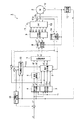
本発明の第1の実施形態となる制御装置1は、図1に示すように、車両を駆動するモータ2の動作を制御するものであり、モータ2に印加する電圧の振幅及び位相を制御する電圧制御モードとモータ2に供給する電流を制御する電流制御モードとの2つの制御モードを有する。本実施形態では、制御装置1は、指令値生成部3,指令値生成部4,電流制御器5,電圧制御器6,制御切替器7,dq軸→UVW相変換器8,PWM変換器9,インバータ(INV.)10,電流センサ11a,11b,位置検出器12,回転数演算器13,UVW相→dq軸変換器14,干渉電圧補正器15,及びトルク偏差(ΔT)補正器16を備える。
[Configuration of control device]
As shown in FIG. 1, the
指令値生成部3は、トルク指令値T*,モータ2の機械角速度ω,及び直流電源17の電圧Vdcと電流制御モードにおけるdq軸電流指令値id *,iq *及びdq軸干渉電圧指令値vd_dcpl *,vq_dcpl *との対応関係を示すテーブルを有する。指令値生成部3は、トルク指令値T*,回転数演算器13から出力されるモータ2の機械角速度ω,及び直流電源17の電圧Vdcに対応するdq軸電流指令値id *,iq *及びdq軸干渉電圧指令値vd_dcpl *,vq_dcpl *をテーブルから検索し、検索されたdq軸電流指令値id *,iq *及びdq軸干渉電圧指令値vd_dcpl *,vq_dcpl *を出力する。このように指令値生成部3は、オープンループ方式によりdq軸電流指令値id *,iq *及びdq軸干渉電圧指令値vd_dcpl *,vq_dcpl *を制御する。
The command value generation unit 3 includes a torque command value T * , a mechanical angular velocity ω of the
指令値生成部4は、トルク指令値T*,モータ2の機械角速度ω,及び直流電源17の電圧Vdcと電圧制御モードにおける電圧振幅指令値va *及び電圧位相指令値α*との対応関係を示すテーブルを有する。指令値生成部4は、トルク指令値T*,回転数演算器13から出力されるモータ2の機械角速度ω,及び直流電源17の電圧Vdcに対応する電圧振幅指令値va *及び電圧位相指令値α*をテーブルから検索し、検索された電圧振幅指令値va *及び電圧位相指令値α*を出力する。このように指令値生成部4は、オープンループ方式により電圧振幅指令値va *及び電圧位相指令値α*を制御する。
Corresponding command
電流制御器5は、指令値生成部3から出力されたdq軸電流指令値id *,iq *及びdq軸干渉電圧指令値vd_dcpl *,vq_dcpl *とUVW相→dq軸変換器14から出力されるdq軸電流検出値id,iqとを用いて電流偏差比例積分(PI)増幅と非干渉制御からなる一般的な電流ベクトル制御演算を行うことにより、dq軸電圧指令値vd1 *,vq1 *を生成,出力する(詳細は後述)。なお“非干渉制御”とは、モータ2に供給する電流をモータ2の2次磁束に直交するq軸電流成分と2次磁束に対し平行なd軸電流成分とに分離して電流制御を行う電流ベクトル制御において、電流、q軸,d軸のインダクタンス、及びモータ2の機械回転数の作用によって、d軸電流成分及びq軸電流成分がそれぞれq軸電圧及びd軸電圧として他方の電流成分に干渉することによる影響を打ち消す制御を意味し、具体的には干渉電圧指令値を用いて電圧指令値を補正する制御を意味する。
The
電圧制御器6は、以下の数式1を利用して指令値生成部4から出力された電圧振幅指令値va *及び電圧位相指令値α*からdq軸電圧指令値vd2 *,vq2 *を算出,出力する。

制御切替器7は、モータ2の制御モードが電流制御モードである場合、電流制御器5から出力されたdq軸電圧指令値vd1 *,vq1 *を電流制御モードにおけるdq軸電圧指令値vd *,vq *として出力し、モータ2の制御モードが電圧制御モードである場合には、電圧制御器6から出力されたdq軸電圧指令値vd2 *,vq2 *を電圧制御モードにおけるdq軸電圧指令値vd *,vq *として出力する。dq軸→UVW相変換器8は、以下の数式2を利用して制御切替器7から出力されたdq軸電圧指令値vd1 *,vq1 *と位置検出器12により検出されたモータ2の回転子の電気角θからU相,V相,及びW相の三相の電圧指令値vu *,vv *,vw *を算出,出力する。
PWM変換器9は、dq軸→UVW相変換器8から出力されたU相,V相,及びW相の三相の電圧指令値vu *,vv *,vw *に対応するインバータ10の駆動信号Duu *,Dul *,Dvu *,Dvl *,Dwu *,Dwl *を生成,出力する。なお駆動信号Duu *,Dul *はそれぞれU相に対応する上段及び下段のスイッチング素子に対する信号を示し、駆動信号Dvu *,Dvl *はそれぞれV相に対応する上段及び下段のスイッチング素子に対する信号を示し、駆動信号Dwu *,Dwl *はそれぞれW相に対応する上段及び下段のスイッチング素子に対する信号を示す。
The
インバータ10は、PWM変換器8から出力された駆動信号Duu *,Dul *,Dvu *,Dvl *,Dwu *,Dwl *に従って対応するスイッチング素子をオン/オフすることにより直流電源17の電圧Vdcを三相の交流電圧vu,vv,vwに変換してモータ2に出力する。電流センサ11a,11bは、U相とV相の電流値iu,ivを検出してUVW相→dq軸変換器14に出力する。本実施形態のように、電流センサを二相だけに取り付ける場合、検出しない残り1相(本実施形態ではW相)の電流値は以下の数式3から算出することができる。
![]()
![]()
位置検出器12は、モータ2の回転子の電気角θを検出してdq軸→UVW相変換器8,回転数演算器13,及びUVW相→dq軸変換器14に出力する。回転数演算器13は、モータ2の回転子の電気角θの時間変化量からモータ2の機械角速度ωを算出して指令値生成部3,指令値生成部4,干渉電圧補正器15,及びトルク偏差補正器16に出力する。UVW相→dq軸変換器14は以下の数式4を利用して電流センサ11a,11bにより検出されたU相とV相の電流値iu,ivと位置検出器12により検出されたモータ2の回転子の電気角θからdq軸電流検出値id,iqを算出する。
干渉電圧補正器15は、モータ2の出力トルクに対しマグネットトルクが支配的である場合、制御モードの切替前のd軸電流検出値idと切替後のd軸電流指令値id *の差分Δid(=id−id *)を以下の数式5に代入することによりq軸干渉電圧補正値Δvq_dcpl *を算出する。なお数式6中、パラメータωはモータ2の機械角速度を示し、パラメータLdはd軸のインダクタンスを示す。また“モータの出力に対しマグネットトルクが支配的である”とは、マグネットトルクのトルク波形の積分強度がリラクタンストルクのトルク波形の積分強度より大きいことを意味する。
![]()
![]()
トルク偏差補正器16は、モータ2の出力トルクに対しマグネットトルクが支配的である場合、制御モードの切替前のq軸電流検出値iqと切替後のq軸電流指令値iq *の差分Δiq(=iq−iq *)を以下の数式6に代入することによりトルク目標値に対するモータ2の出力トルクの差をトルク偏差ΔTとして算出,出力する。なお数式6中、パラメータωはモータ2の機械角速度を示し、パラメータφaはモータ2の磁束密度を示す。このトルク偏差ΔTは、トルク目標値T0 *と加算されることによりトルク指令値T*として指令値生成部3,4に入力される。
![]()
![]()
〔電流制御器の構成〕
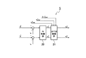
電流制御器5は、図2に示すように、PI制御部20と非干渉制御部21を備える。PI制御部20は、d軸電流検出値idとd軸電流指令値id *の差分Δid(=id−id *)及びq軸電流検出値iqとq軸電流指令値iq *の差分Δiq(=iq−iq *)を比例積分(PI)演算増幅することによりdq軸電圧指令値vd1 *,vq1 *を演算する。非干渉制御部21は、干渉電圧補正器15から出力されたq軸干渉電圧補正値Δvq_dcpl *を指令値生成部3から出力されたq軸干渉電圧指令値vq_dcpl *に加算することによりq軸干渉電圧指令値vq_dcpl *を補正した後、dq軸干渉電圧指令値vd_dcpl *,vq_dcpl *に対応するdq軸干渉電圧値vd_dcpl,vq_dcplをテーブルから読み出すオープンループ方式によりdq軸干渉電圧vd_dcpl,vq_dcplを演算する。そして非干渉制御部21は、PI制御部20により演算されたdq軸電圧指令値vd1 *,vq1 *にdq軸干渉電圧値vd_dcpl,vq_dcplを加算した値をdq軸電圧指令値vd1 *,vq1 *として出力する。
[Configuration of current controller]
As shown in FIG. 2, the
〔非干渉制御部の構成〕
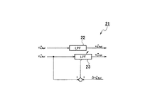
非干渉制御部21は、図3に示すように、ローパスフィルタ(LPF)22,23を備える。ローパスフィルタ22は、指令値生成部3から出力されたd軸干渉電圧指令値vd_dcpl *から高周波成分を除去して出力する。ローパスフィルタ23は、指令値生成部3から出力されたq軸干渉電圧指令値vq_dcpl *から高周波成分を除去して出力する。ローパスフィルタ23の出力初期値は、モータ2の制御モードが電圧制御モードから電流制御モードに切り替えられた時点においてq軸干渉電圧指令値vq_dcpl *にq軸干渉電圧補正値Δvq_dcpl *を加算した値に設定される。これにより、ローパスフィルタ23の出力値は、モータ2の制御モードが電圧制御モードから電流制御モードに切り替えられた時点から時間が経過するのに伴い、q軸干渉電圧指令値vq_dcpl *にq軸干渉電圧補正値Δvq_dcpl *を加算した値からq軸干渉電圧指令値vq_dcpl *に収束する。
[Configuration of non-interference control unit]
As shown in FIG. 3, the
〔モータ制御動作〕
次に、上記制御装置1によるモータ2の制御動作について説明する。
[Motor control operation]
Next, the control operation of the
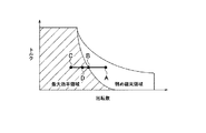
図4は、モータ2の出力特性と制御切替ポイントの関係を示し、縦軸及び横軸はそれぞれモータ2の出力トルク及び機械回転数を示す。図中に示す最大効率領域とは、モータ2がトルク目標値を出力し得る最小の電流(最大効率電流)を選択してモータ2の動作を制御する領域を示す。一般に、モータ2の機械回転数が上昇すると、誘起電圧が上昇することによってモータ2の端子電圧の大きさはインバータ10が出力可能な電圧の最大値に達する。このためモータ2の端子電圧が所定値以上になった場合には、磁石磁束を弱める電流を増やすことによってモータ2の端子電圧がインバータ10が出力可能な電圧の最大値を超えないようにモータ2の動作を制御する必要がある。具体的には、電圧振幅をインバータ10が出力可能な最大値で一定にし、電圧位相を制御することでトルクを所望の値にすることにより、結果的に磁石磁束を弱める電流を流し、モータ2の端子電圧がインバータ10が出力可能な電圧の最大値を超えないようにする。図4においてはこの磁石磁束を弱める電流を流す制御領域を弱め磁束領域と表記する。
FIG. 4 shows the relationship between the output characteristics of the
モータ2の回転子の回転数が上昇してモータ2の制御モードが電流制御モードから電圧位相制御モードに切り替わる際は図4に示すB点のように上述の最大効率領域と弱め磁束領域の境界線上で行うことが望ましい。しかしながらモータ2の機械回転数が下がって電圧制御モードから電流制御モードに切り替わる際も同じ境界線上で行うと、制御切替が頻発(チャタリング)する恐れがある。そこで実際には電圧制御モードから電流制御モードに切り替える際は図4に示すD点で切り替えるようにして、制御モード切替のタイミングにヒステリシスを設けるようにする。以下、図5に示すフローチャートを参照して、この制御モード切替処理について詳しく説明する。
When the rotational speed of the rotor of the
〔制御モード切替処理〕
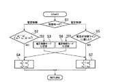
図5に示すフローチャートは、制御装置1の電源がオフ状態からオン状態に切り換えられたタイミングで開始となり、制御モード切替処理はステップS1の処理に進む。なおこの制御モード切替処理は所定制御周期毎に繰り返し実行されるものとする。
[Control mode switching process]
The flowchart shown in FIG. 5 starts at the timing when the power supply of the
ステップS1の処理では、制御切替器7が、現在の制御モードが電流制御モードと電圧制御モードのどちらであるかを判別する。判別の結果、現在の制御モードが電流制御モードである場合、制御切替器7は制御モード切替処理をステップS2の処理に進める。一方、現在の制御モードが電圧制御モードである場合には、制御切替器7は制御モード切替処理をステップS5の処理に進める。
In step S1, the
ステップS2の処理では、制御切替器7が、dq軸電圧指令値vd1 *,vq1 *から算出される電圧振幅(vd1 *2+vq1 *2)1/2が電圧振幅指令値va *以上であるか否かを判別する。判別の結果、電圧振幅(vd1 *2+vq1 *2)1/2が電圧振幅指令値va *以上である場合、制御切替器7は、ステップS3の処理としてモータ2の制御モードを電流制御モードから電圧制御モードに切り替えた後、制御モード切替処理をステップS7の処理に進める。一方、電圧振幅(vd1 *2+vq1 *2)1/2が電圧振幅指令値va *未満である場合には、制御切替器7は、制御モードを電流制御モードに維持するべく、制御モード切替処理をステップS4の処理に進める。
In the processing of step S2, the
ステップS4の処理では、制御切替器7が、電流制御器5から出力されたdq軸電圧指令値vd1 *,vq1 *をdq軸電圧指令値vd *,vq *として出力する。これにより、ステップS4の処理は完了し、制御モード切替処理はステップS1の処理に戻る。
In step S4, the
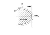
ステップS5の処理では、制御切替器7が、dq軸電流検出値id,iqが図6に示す切替ラインL2に達したか否かを判別する。なお図6に示す実線L1はdq軸電流座標上における最大効率電流を示し、最大効率領域内における電流指令値はこの最大効率電流となるように制御される。電圧制御モードから電流制御モードに切り替える際は、この最大効率電流を示す実線L1上で行うことが望ましいが、前述のようにチャタリングを回避するため、最大効率電流にヒステリシスを加えた点線L2のような切替ラインを設定する。制御切替器7は、予め記憶された点線L2の軌跡データを利用してdq軸電流検出値id,iqが切替ラインL2に達したか否かを判別する。判別の結果、dq軸電流検出値id,iqが切替ラインL2に達した場合、制御切替器7は、ステップS6の処理としてモータ2の制御モードを電圧制御モードから電流制御モードに切り替えた後、制御モード切替処理をステップS4の処理に進める。一方、dq軸電流検出値id,iqが切替ラインL2に達していない場合には、制御切替器7は、制御モードを電圧制御モードに維持するべく、制御モード切替処理をステップS7の処理に進める。
In the process of step S5, the
ステップS7の処理では、制御切替器7が、電圧制御器6から出力されたdq軸電圧指令値vd2 *,vq2 *をdq軸電圧指令値vd *,vq *として出力する。これにより、ステップS7の処理は完了し、制御モード切替処理はステップS1の処理に戻る。
In the process of step S7, the
〔干渉電圧補正処理〕
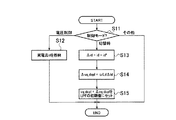
次に、図7に示すフローチャートを参照して、本発明の第1の実施形態となる干渉電圧補正処理の流れについて説明する。図7に示すフローチャートは、制御装置1の電源がオフ状態からオン状態に切り換えられたタイミングで開始となり、干渉電圧補正処理はステップS11の処理に進む。なおこの干渉電圧補正処理は所定制御周期毎に繰り返し実行されるものとする。
[Interference voltage correction processing]
Next, the flow of interference voltage correction processing according to the first embodiment of the present invention will be described with reference to the flowchart shown in FIG. The flowchart shown in FIG. 7 starts at the timing when the power supply of the
ステップS11の処理では、干渉電圧補正器15が、現在の制御モードが電圧制御モード,電流制御モード,電圧制御モードから電流制御モードへの制御モード切替時,電流制御モードから電圧制御モードへの制御モード切替時のいずれであるかを判別する。判別の結果、現在の制御モードが電圧制御モードである場合、干渉電圧補正器15は干渉電圧補正処理をステップS12の処理に進める。現在の制御モードが電流制御モード又は電流制御モードから電圧制御モードへの制御モード切替時である場合には、干渉電圧補正器15は一連の干渉電圧補正処理を終了する。現在の制御モードが電圧制御モードから電流制御モードへの制御モード切替時である場合には、干渉電圧補正器15は干渉電圧補正処理をステップS13の処理に進める。
In the process of step S11, the
ステップS12の処理では、干渉電圧補正器15が、UVW→dq軸変換器14から入力されたd軸電流検出値idを記憶する。なお前回の干渉電圧補正処理によりd軸電流検出値idが記憶されている場合、干渉電圧補正器15は、今回のd軸電流検出値idにより前回のd軸電流検出値idを上書きする。これにより、ステップS12の処理は完了し、一連の干渉電圧補正処理は終了する。
In the process of step S12, the
ステップS13の処理では、干渉電圧補正器15が、ステップS12の処理により記憶された制御モードの切替前のd軸電流検出値idと切替後のd軸電流指令値id *の差分Δid(=id−id *)を算出する。これにより、ステップS13の処理は完了し、干渉電圧補正処理はステップS14の処理に進む。
In the process of step S13, the
ステップS14の処理では、干渉電圧補正器15が、ステップS13の処理により算出された差分値Δidを既述の数式6に代入することによりq軸干渉電圧補正値Δvq_dcpl *を算出し、算出されたq軸干渉電圧補正値Δvq_dcpl *を電流制御器5に出力する。これにより、ステップS14の処理は完了し、干渉電圧補正処理はステップS15の処理に進む。
In the process of step S14, the
ステップS15の処理では、電流制御器5が、指令値生成部3から出力されたq軸干渉電圧指令値vq_dcpl *にステップS14の処理により算出されたq軸干渉電圧補正値Δvq_dcpl *を加算した値をローパスフィルタ23の出力初期値に設定する。これにより、ステップS15の処理は完了し、一連の干渉電圧補正処理は終了する。
In the process of step S15, the
〔トルク脈動及びトルク段差〕
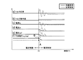
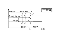
図8は、本発明の実施形態となる制御装置1(本願発明)及び従来の制御装置(従来技術)においてモータ2の制御モードを電圧制御モードから電流制御モードに切り替えた際の(a)トルク応答,(b)トルク指令値,(c)q軸電流検出値,(d)d軸電流検出値,(e)q軸電圧指令値,及び(f)q軸干渉電圧の時間変化を示す波形図である。また図9は、図8に示す(e)q軸電圧指令値及び(f)q軸干渉電圧の時間変化の拡大波形図である。なお図8,9に示す点Aは上述の干渉電圧補正処理による補正前の干渉電圧値を示し、点Bは上述の干渉電圧補正処理による補正後の干渉電圧値を示す。また時刻T=T1はモータ2の制御モードを電圧制御モードから電流制御モードに切り替えた時間を示す。
[Torque pulsation and torque step]
FIG. 8 shows (a) torque when the control mode of the
モータ2の制御モードを電圧制御モードから電流制御モードに切り替える際、切替前の電流検出値と切替後の電流指令値が連続的になる地点で切り替えることが望ましい。しかしながら実際には、チャタリングを防止するためにヒステリシスが与えられていることから、制御モードは電流にヒステリシスを与えた地点で切り替わる。この場合、従来技術では切替直前の電流検出値と切替後の電流指令値に差が生じ、切替前後で電流が急変するので、結果としてトルク脈動が生じる(図8(a)の点線参照)。このトルク脈動は、制御モードの切替時に、切替前の実電流値と切替後の電流指令値の変化に対し、切替後の電流制御モードにおける非干渉制御の干渉電圧値(図9に示す電圧E)と電流偏差比例積分制御の電圧値(図9に示す電圧D)の比率(D/E)が適切な値になっていないために発生する。これに対して本願発明では、既述の通り、制御モードの切替時に、切替前の実電流値と切替後の電流指令値の変化に基づいて干渉電圧補正値を算出して干渉電圧値を補正することにより、切替前の実電流値と切替後の電流指令値の変化に対し、電流制御モードにおける非干渉制御の干渉電圧値と電流偏差比例積分制御の電圧値の比率(D/E)が適切な値になるようにした。この結果、干渉電圧vq_dcplが図8(f)及び図9(f)に実線で示すような理想的な応答を示し、図8(a)に実線で示すようにトルク脈動を抑制することができる。
When the control mode of the
電流制御モードでは指令値生成部3により各指令値が制御され、電圧制御モードでは指令値生成部4により各指令値が制御されている。従来技術では、モータ2の温度と指令値生成部3,4が参照するテーブルデータが作成された時のモータ2の温度が異なる場合、電流制御モードにおけるトルクは図8(a)に点線で示す値となり、電圧制御モードにおける出力トルクとの間に段差が生じてしまう。モータ2の出力トルクは磁束と電流によって決まるが、電流制御モード時は電流は所望の値に制御されているので、モータ2の温度変化による磁束の変化がトルク誤差要因になる。一方、電圧制御モードでは電流を制御していないので、磁束と電流が電動機の温度変化に伴って変化しトルク誤差の要因になる。つまり、電流制御モードと電圧位相制御モードではモータ2の温度に対するトルク誤差特性が異なることから、出力トルクの段差が生じる。これに対し本願発明では、既述の通り、切替による出力トルクの変化を算出し、切替前後の出力トルクが一定となるよう、図8(b)に示すトルク指令値のように切替後のトルク指令値を補正するようにしているので、図8(a)に実線で示すようにトルク段差が解消される。
In the current control mode, the command value generator 3 controls each command value, and in the voltage control mode, the
以上の説明から明らかなように、本発明の第1の実施形態となる制御装置1によれば、モータ2の制御モードを電圧制御モードから電流制御モードに切り替える際、モータ2の出力トルクに対しマグネットトルクが支配的である場合、干渉電圧補正器15が、制御モードの切替前のd軸電流検出値idと切替後のd軸電流指令値id *の差分Δidに基づいてq軸干渉電圧補正値Δvq_dcpl *を算出し、電流制御器5が、q軸干渉電圧補正値Δvq_dcpl *を用いて指令値生成部3から出力されたq軸干渉電圧指令値vq_dcpl *を補正する。そしてこのような構成によれば、切替前のd軸電流検出値idと切替後のd軸電流指令値id *の変化に対し、電流制御モードにおける非干渉制御の干渉電圧値と電流偏差比例積分制御の電圧値の比率が適切な値になるので、モータ2の制御モードを電圧制御モードから電流制御モードに切り替える際にトルク脈動が発生することを抑制できる。
As is clear from the above description, according to the
また本発明の第1の実施形態となる制御装置1によれば、トルク偏差補正器16が、モータ2の出力トルクに対しマグネットトルクが支配的である場合、制御モードの切替前のq軸電流検出値iqと切替後のq軸電流指令値iq *の差分Δiq(=iq−iq *)に基づいて切替動作による出力トルクの変化量を算出し、切替前後の出力トルクが一定となるようトルク指令値を補正するので、モータ2の制御モードの切替前後でトルク段差が発生することを抑制できる。なおトルク偏差補正器16は、トルク指令値と電流指令値の少なくとも一方を補正するようにしてもよい。
Further, according to the
〔第2の実施形態〕
次に、図10乃至図12を参照して、本発明の第2の実施形態となる交流電動機の制御装置21の構成について説明する。
[Second Embodiment]
Next, with reference to FIG. 10 to FIG. 12, the configuration of the AC
〔制御装置の構成〕
本実施形態では、電流制御器5,干渉電圧補正器15,及びトルク偏差補正器16の構成と干渉電圧補正処理の流れが上記第1の実施形態におけるそれと異なる。そこで以下では、電流制御器5,干渉電圧補正器15,及びトルク偏差補正器16の構成と本実施形態における干渉電圧補正処理についてのみ説明する。
[Configuration of control device]
In the present embodiment, the configuration of the
〔干渉電圧補正器の構成〕
干渉電圧補正器15は、制御モードの切替前のd軸電流検出値idと切替後のd軸電流指令値id *の差分Δid(=id−id *)及び制御モードの切替前のq軸電流検出値iqと切替後のq軸電流指令値iq *の差分Δiq(=iq−iq *)を以下の数式7に代入することによりd軸干渉電圧補正値Δvd_dcpl *及びq軸干渉電圧補正値Δvq_dcpl *を算出する。なお数式7中、パラメータωはモータ2の機械角速度、パラメータLd,Lqはそれぞれd軸及びq軸のインダクタンスを示す。
〔電流制御器の構成〕
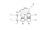
電流制御器5は、図10に示すように、PI制御部20と非干渉制御部24を備える。PI制御部20は、d軸電流検出値idとd軸電流指令値id *の差分Δid(=id−id *)及びq軸電流検出値iqとq軸電流指令値iq *の差分Δiq(=iq−iq *)を比例・積分PI演算増幅することによりdq軸電圧指令値vd1 *,vq1 *を演算する。非干渉制御部24は、干渉電圧補正器15から出力されたd軸干渉電圧補正値Δvd_dcpl *及びq軸干渉電圧補正値Δvq_dcpl *を指令値生成部3から出力されたd軸干渉電圧指令値vd_dcpl *及びq軸干渉電圧指令値vq_dcpl *に加算することによりd軸干渉電圧指令値vd_dcpl *及びq軸干渉電圧指令値vq_dcpl *を補正した後、dq軸干渉電圧指令値vd_dcpl *,vq_dcpl *に対応するdq軸干渉電圧値vd_dcpl,vq_dcplをテーブルから読み出すオープンループ方式によりdq軸干渉電圧vd_dcpl,vq_dcplを演算する。そして非干渉制御部24は、PI制御部20により演算されたdq軸電圧指令値vd1 *,vq1 *にdq軸干渉電圧値vd_dcpl,vq_dcplを加算した値をdq軸電圧指令値vd1 *,vq1 *として出力する。
[Configuration of current controller]
As shown in FIG. 10, the
〔非干渉制御部の構成〕
非干渉制御部24は、図11に示すように、ローパスフィルタ(LPF)25,26を備える。ローパスフィルタ25は、指令値生成部3から出力されたd軸干渉電圧指令値vd_dcpl *から高周波成分を除去して出力する。ローパスフィルタ26は、指令値生成部3から出力されたq軸干渉電圧指令値vq_dcpl *から高周波成分を除去して出力する。ローパスフィルタ25の出力初期値は、モータ2の制御モードが電圧制御モードから電流制御モードに切り替えられた時点においてd軸干渉電圧指令値vd_dcpl *にd軸干渉電圧補正値Δvd_dcpl *を加算した値に設定される。これにより、ローパスフィルタ25の出力値は、モータ2の制御モードが電圧制御モードから電流制御モードに切り替えられた時点から時間が経過するのに伴い、d軸干渉電圧指令値vd_dcpl *にd軸干渉電圧補正値Δvd_dcpl *を加算した値からd軸干渉電圧指令値vd_dcpl *に収束する。ローパスフィルタ26の出力初期値は、モータ2の制御モードが電圧制御モードから電流制御モードに切り替えられた時点においてq軸干渉電圧指令値vq_dcpl *にq軸干渉電圧補正値Δvq_dcpl *を加算した値に設定される。これにより、ローパスフィルタ26の出力値は、モータ2の制御モードが電圧制御モードから電流制御モードに切り替えられた時点から時間が経過するのに伴い、q軸干渉電圧指令値vq_dcpl *にq軸干渉電圧補正値Δvq_dcpl *を加算した値からq軸干渉電圧指令値vq_dcpl *に収束する。
[Configuration of non-interference control unit]
The
〔トルク偏差補正器の構成〕
トルク偏差補正器16は、制御モードの切替前のd軸電流検出値idと切替後のd軸電流指令値id *の差分Δid(=id−id *)及び制御モードの切替前のq軸電流検出値iqと切替後のq軸電流指令値iq *の差分Δiq(=iq−iq *)を以下の数式8に代入することによりトルク偏差ΔTを算出,出力する。なお数式8中、パラメータωはモータ2の機械角速度を示し、パラメータφaはモータ2の磁束密度を示す。このトルク偏差ΔTは、トルク目標値T0 *と加算されることによりトルク指令値T*として指令値生成部3,4に入力される。
![]()
![]()
〔干渉電圧補正処理〕
次に、図12に示すフローチャートを参照して、本発明の第2の実施形態となる干渉電圧補正処理の流れについて説明する。図12に示すフローチャートは、制御装置1の電源がオフ状態からオン状態に切り換えられたタイミングで開始となり、干渉電圧補正処理はステップS21の処理に進む。なおこの干渉電圧補正処理は所定制御周期毎に繰り返し実行されるものとする。
[Interference voltage correction processing]
Next, the flow of interference voltage correction processing according to the second embodiment of the present invention will be described with reference to the flowchart shown in FIG. The flowchart shown in FIG. 12 starts at the timing when the power supply of the
ステップS21の処理では、干渉電圧補正器15が、現在の制御モードが電圧制御モード,電流制御モード,電圧制御モードから電流制御モードへの制御モード切替時,電流制御モードから電圧制御モードへの制御モード切替時のいずれであるかを判別する。判別の結果、現在の制御モードが電圧制御モードである場合、干渉電圧補正器15は干渉電圧補正処理をステップS22の処理に進める。現在の制御モードが電流制御モード又は電流制御モードから電圧制御モードへの制御モード切替時である場合には、干渉電圧補正器15は一連の干渉電圧補正処理を終了する。現在の制御モードが電圧制御モードから電流制御モードへの制御モード切替時である場合には、干渉電圧補正器15は干渉電圧補正処理をステップS23の処理に進める。
In the process of step S21, the
ステップS22の処理では、干渉電圧補正器15が、UVW→dq軸変換器14から入力されたd軸電流検出値id及びq軸電流検出値iq記憶する。なお前回の干渉電圧補正処理によりd軸電流検出値id及びq軸電流検出値iqが記憶されている場合、干渉電圧補正器15は、今回のd軸電流検出値id及びq軸電流検出値iqにより前回のd軸電流検出値id及びq軸電流検出値iqを上書きする。これにより、ステップS22の処理は完了し、一連の干渉電圧補正処理は終了する。
In the process of step S22, the
ステップS23の処理では、干渉電圧補正器15が、ステップS22の処理により記憶された制御モードの切替前のd軸電流検出値id及びq軸電流検出値iqと切替後のd軸電流指令値id *及びq軸電流指令値iq *の差分Δid(=id−id *)及び差分Δiq(=iq−iq *)を算出する。これにより、ステップS23の処理は完了し、干渉電圧補正処理はステップS24の処理に進む。
In the process of step S23, the
ステップS24の処理では、干渉電圧補正器15が、ステップS23の処理により算出された差分値Δid及び差分Δiqを既述の数式7に代入することによりd軸干渉電圧補正値Δvd_dcpl *及びq軸干渉電圧補正値Δvq_dcpl *を算出し、算出されたd軸干渉電圧補正値Δvd_dcpl *及びq軸干渉電圧補正値Δvq_dcpl *を電流制御器5に出力する。これにより、ステップS24の処理は完了し、干渉電圧補正処理はステップS25の処理に進む。
In the process of step S24, the
ステップS25の処理では、電流制御器5が、指令値生成部3から出力されたq軸干渉電圧指令値vd_dcpl *及びq軸干渉電圧指令値vq_dcpl *にステップS24の処理により算出されたd軸干渉電圧補正値Δvd_dcpl *及びq軸干渉電圧補正値Δvq_dcpl *を加算した値をそれぞれローパスフィルタ25及びローパスフィルタ26の出力初期値に設定する。これにより、ステップS25の処理は完了し、一連の干渉電圧補正処理は終了する。
In the process of step S25, the
以上の説明から明らかなように、本発明の第2の実施形態となる制御装置21によれば、モータ2の制御モードを電圧制御モードから電流制御モードに切り替える際、干渉電圧補正器15が、制御モードの切替前のd軸電流検出値idと切替後のd軸電流指令値id *の差分Δidに基づいてq軸干渉電圧補正値Δvq_dcpl *を算出し、制御モードの切替前のq軸電流検出値iqと切替後のq軸電流指令値iq *の差分Δiqに基づいてd軸干渉電圧補正値Δvd_dcpl *を算出する。そして電流制御器5は、q軸干渉電圧補正値Δvq_dcpl *を用いて指令値生成部3から出力されたq軸干渉電圧指令値vq_dcpl *を補正し、d軸干渉電圧補正値Δvd_dcpl *を用いて指令値生成部3から出力されたd軸干渉電圧指令値vd_dcpl *を補正する。そしてこのような構成によれば、切替前のd軸電流検出値id及びq軸電流検出値iqと切替後のd軸電流指令値id *及びq軸電流検出値iq *の変化に対し、電流制御モードにおける非干渉制御の干渉電圧値と電流偏差比例積分制御の電圧値の比率が適切な値になるので、モータ2の制御モードを電圧制御モードから電流制御モードに切り替える際にトルク脈動が発生することを抑制できる。
As is clear from the above description, according to the
また本発明の第2の実施形態となる制御装置21によれば、トルク偏差補正器16が、制御モードの切替前のd軸電流検出値id及びq軸電流検出値iq,切替後のd軸電流指令値id *及びq軸電流指令値iq *,及びこれら電流値に基づくdq軸インダクタンス値Ld,Lqを用いて切替動作による出力トルクの変化量を算出し、切替前後の出力トルクが一定となるようトルク指令値を補正するので、モータ2の制御モードの切替前後でトルク段差が発生することを抑制できる。
Further, according to the
〔第3の実施形態〕
次に、図13を参照して、本発明の第3の実施形態となる交流電動機の制御装置の構成について説明する。
[Third Embodiment]
Next, with reference to FIG. 13, the structure of the control apparatus of the alternating current motor which becomes the 3rd Embodiment of this invention is demonstrated.
〔制御装置の構成〕
本発明の第3の実施形態となる制御装置31は、図13に示すように、指令値生成部4,電流制御器5,電圧制御器6,制御切替器7,dq軸→UVW相変換器8,PWM変換器9,インバータ10,電流センサ11a,11b,位置検出器12,回転数演算器13,UVW相→dq軸変換器14,干渉電圧補正器15,トルク偏差補正器16,指令値生成部32,LPF33,及び非干渉制御部34を備える。なお上記第1の実施形態となる制御装置1と同じ構成要素には同符号を付与することにより以下ではその説明を省略する。
[Configuration of control device]
As shown in FIG. 13, the
指令値生成部32は、トルク指令値T*,モータ2の機械角速度ω,及び直流電源17の電圧Vdcと電流制御モードにおけるdq軸電流指令値id *,iq *との対応関係を示すテーブルを有する。指令値生成部32は、トルク指令値T*,回転数演算器13から出力されるモータ2の機械角速度ω,及び直流電源17の電圧Vdcに対応するdq軸電流指令値id *,iq *をテーブルから検索し、検索されたdq軸電流指令値id *,iq *を出力する。LPF33は、指令値生成部32から出力されたdq軸電流指令値id *,iq *に対し電流応答相当のフィルタ処理を施すことによりdq軸電流応答推定値id *,iq *を生成,出力する。非干渉制御部34は、dq軸電流応答推定値id *,iq *を用いてdq軸干渉電圧指令値vd_dcpl *,vq_dcpl *を算出して電流制御器5に出力する。
The command
このように本実施形態における制御装置31は、dq軸電流指令値id *,iq *に対し電流応答相当のフィルタ処理を施すことにより得られるdq軸電流応答推定値id *,iq *を用いて非干渉制御で用いるdq軸干渉電圧指令値vd_dcpl *,vq_dcpl *を算出するオープンループ方式となっており、モータ2の制御モードを電圧制御モードから電流制御モードに切り替える際、モータ2の出力トルクに対しマグネットトルクが支配的である場合、電流制御器5は、切替前のd軸電流検出値idを用いて非干渉制御部34から出力されたq軸干渉電圧指令値vq_dcpl *を補正する。一方、モータ2の出力トルクに対しマグネットトルクが支配的でない場合には、電流制御器5は、切替前のd軸電流検出値id及びq軸電流検出値iqを用いてそれぞれ非干渉制御部34から出力されたq軸干渉電圧指令値vq_dcpl *及びd軸干渉電圧指令値vd_dcpl *を補正する。そしてこのような構成によれば、切替前の電流検出値と切替後の電流指令値の変化に対し、電流制御モードにおける非干渉制御の干渉電圧値と電流偏差比例積分制御の電圧値の比率が適切な値になるので、モータ2の制御モードを電圧制御モードから電流制御モードに切り替える際にトルク脈動が発生することを抑制できる。
As described above, the
〔第4の実施形態〕
最後に、図14を参照して、本発明の第4の実施形態となる交流電動機の制御装置の構成について説明する。
[Fourth Embodiment]
Finally, with reference to FIG. 14, the structure of the control apparatus of the alternating current motor which becomes the 4th Embodiment of this invention is demonstrated.
〔制御装置の構成〕
本発明の第4の実施形態となる制御装置41は、図14に示すように、指令値生成部3,指令値生成部4,電流制御器5,電圧制御器6,制御切替器7,dq軸→UVW相変換器8,PWM変換器9,インバータ10,電流センサ11a,11b,位置検出器12,回転数演算器13,UVW相→dq軸変換器14,干渉電圧補正器15,PI制御部42,電力演算部43,トルク推定器44,LPF45a,45b,及びオフセット量演算部46を備える。なお上記第1の実施形態となる制御装置1と同じ構成要素には同符号を付与することにより以下ではその説明を省略する。
[Configuration of control device]
As shown in FIG. 14, the
PI制御部42はトルク推定器44から出力されるトルク推定値T^とトルク目標値T0 *の偏差を比例積分増幅し、増幅後の偏差をトルク目標値T0 *から減算することによりトルク指令値T*を算出,出力する。電力演算部43は、制御切替器7から出力されたdq軸電圧指令値vd *,vq *とUVW→dq軸変換器14から出力されたdq軸電流検出値id *,iq *の積をモータ2の消費電力として演算出力する。トルク推定器44は、以下の数式9を用いて電力演算部43から出力されたモータ2の消費電力とモータ2の回転角速度ωからトルク推定値T^を演算,出力する。なお数式8は銅損や鉄損等の損失を無視しているが、損失分を考慮してトルク推定値T^を算出してもよい。
![]()
![]()
オフセット量演算部46は、モータ2の制御モードを電圧位相制御モードから電流制御モードに切替える直前にのみ動作し、d軸電流検出値id及びq軸電流検出値iqとd軸電流指令値id *及びq軸電流指令値iq *の電流偏差Δid0(=id−id *),Δiq0(=iq−iq *)を算出する。LPF45a,45bは、制御モードが電流制御モードである場合のみ動作し、その入力は常に0に設定されている。LPF45a,45bはそれぞれ電流オフセット量Δid,Δiqを出力する。LPF45a,45bの出力初期値は、制御モードが電圧制御モードから電流制御モードに切り替わる直前にそれぞれ電流偏差Δid0,Δiq0に設定される。これにより、ローパスフィルタ45a,45bの出力値は、モータ2の制御モードが電圧制御モードから電流制御モードに切り替えられた時点から時間が経過するのに伴い、電流偏差Δid0,Δiq0から0に収束する。
Offset
このように本発明の第4の実施形態となる制御装置41は、制御モードの切替直前の電流検出値と切替後の電流指令値の偏差を一次遅れで0に収束させつつ、制御モードに関係なく電力フィードバック(トルク推定フィードバック)により出力トルクがトルク目標値に一致するようにトルク指令値を調整する構成になっている。このような構成によれば、上記第1の実施形態の技術的効果と共に、電力フィードバックを高速に行い電流変化を速くできるという技術的効果を得ることができる。なお制御装置41は、制御モードの切替直前の電流指令値と切替後の電流指令値の偏差を一次遅れで0に収束させるようにしてもよい。また制御装置41は、出力トルクがトルク目標値に一致するように電流指令値を調整するようにしてもよい。
As described above, the
本発明に係る切替手段及び補正手段は制御切替器7に対応する。本発明に係る第2の補正手段はトルク偏差補正器16に対応する。本発明に係る第3の補正手段はPI制御部42に対応する。
The switching means and the correction means according to the present invention correspond to the
以上、本発明者らによってなされた発明を適用した実施の形態について説明したが、本実施形態による本発明の開示の一部をなす記述及び図面により本発明は限定されることはない。例えば本実施形態は、モータ2の制御モードを電圧制御モードから電流制御モードに切り替える際に発生するトルク脈動を抑制するためのものであるが、本発明は本実施形態に限定されることはなく、制御モードの切替を行う際に電圧又は電流が急変してトルクが変動する制御全般に対し適用できる。具体的には、異なる指令値生成部により制御される第1の電流制御モードと第2の電流制御モードを有し、これらの間でモータ2の制御モードを切り替える際に適用できる。また図1に示す電圧制御器6を矩形波電圧制御とし、以下の数式10,11を用いて電圧指令値α*と電源電圧Vdcから算出される基本波成分相当のdq軸電圧指令値vd2 *,vq2 *を出力する場合にも適用できる。
![]()
![]()
また制御モードの切替ポイントのヒステリシスの設け方は実施例で示した以外にもさまざま考えられるが、いずれにしてもヒステリシスを設けることにより電圧又は電流が急変し、トルクが変動してしまう制御全般に本発明は適用できる。このように、本実施形態に基づいて当業者等によりなされる他の実施の形態、実施例及び運用技術等は全て本発明の範疇に含まれる。 In addition to the examples shown in the embodiment, there are various ways of providing hysteresis at the control mode switching point. However, in any case, by providing hysteresis, voltage or current changes suddenly and torque changes. The present invention is applicable. As described above, other embodiments, examples, operation techniques, and the like made by those skilled in the art based on the present embodiment are all included in the scope of the present invention.
1:制御装置
2:モータ(交流電動機)
3,4:指令値生成部
5:電流制御器
6:電圧制御器
7:制御切替器
8:dq軸→UVW相変換器
9:PWM変換器
10:インバータ
11a,11b:電流センサ
12:位置検出器
13:回転数演算器
14:UVW相→dq軸変換器
15:干渉電圧補正器
16:トルク偏差(ΔT)補正器
1: Control device 2: Motor (AC motor)
3, 4: Command value generator 5: Current controller 6: Voltage controller 7: Control switch 8: dq axis → UVW phase converter 9: PWM converter 10:
Claims (10)
前記トルク指令値に応じた第2の電圧指令値を算出し、算出された第2の電圧指令値に基づいて交流電動機を制御する電圧制御モードと、
前記電流制御モードと前記電圧制御モードとの間で交流電動機の制御モードを切り替える切替手段と、
前記切替手段が交流電動機の制御モードを前記電圧制御モードから前記電流制御モードに切り替える際、切替前の交流電動機の実電流値に基づいて前記干渉電圧指令値を補正する補正手段と
を備えることを特徴とする交流電動機の制御装置。 A first voltage is calculated by calculating a current command value and an interference voltage command value corresponding to the torque command value, performing non-interference control based on the interference voltage command value, and performing a current vector control calculation based on the current command value. A current control mode for controlling the AC motor by outputting a command value;
A voltage control mode for calculating a second voltage command value corresponding to the torque command value and controlling the AC motor based on the calculated second voltage command value;
Switching means for switching the control mode of the AC motor between the current control mode and the voltage control mode;
When the switching means switches the control mode of the AC motor from the voltage control mode to the current control mode, the switching means comprises correction means for correcting the interference voltage command value based on the actual current value of the AC motor before switching. A control device for an AC electric motor that is characterized.
前記干渉電圧指令値がトルク指令値と干渉電圧指令値の対応関係を示すテーブルを参照することにより算出され、且つ、交流電動機の出力トルクに対しマグネットトルクが支配的である場合、前記補正手段は、制御モードの切替前のd軸電流値と切替後のd軸電流指令値の差に基づいてq軸側の干渉電圧指令値を補正することを特徴とする交流電動機の制御装置。 In the control apparatus for an AC motor according to claim 1,
When the interference voltage command value is calculated by referring to a table showing a correspondence relationship between the torque command value and the interference voltage command value, and the magnet torque is dominant with respect to the output torque of the AC motor, the correction means A control apparatus for an AC motor, wherein a q-axis side interference voltage command value is corrected based on a difference between a d-axis current value before switching the control mode and a d-axis current command value after switching.
前記干渉電圧指令値がトルク指令値と干渉電圧指令値の対応関係を示すテーブルを参照することにより算出される場合、前記補正手段は、制御モードの切替前のq軸電流値と切替後のq軸電流指令値の差に基づいてd軸側の干渉電圧指令値を補正し、制御モードの切替前のd軸電流値と切替後のd軸電流指令値の差に基づいてq軸側の干渉電圧指令値を補正することを特徴とする交流電動機の制御装置。 In the control apparatus for an AC motor according to claim 1,
When the interference voltage command value is calculated by referring to a table indicating a correspondence relationship between the torque command value and the interference voltage command value, the correction unit is configured to change the q-axis current value before switching the control mode and the q value after switching. The interference voltage command value on the d-axis side is corrected based on the difference between the shaft current command values, and the interference on the q-axis side based on the difference between the d-axis current value before switching the control mode and the d-axis current command value after switching. A control apparatus for an AC motor, wherein the voltage command value is corrected.
前記干渉電圧指令値が前記電流指令値に対して電流応答相当のフィルタ処理を施すことにより得られる電流応答推定値を用いて算出され、且つ、交流電動機の出力トルクに対しマグネットトルクが支配的である場合、前記補正手段は、制御モードの切替前のd軸電流値に基づいてq軸側の干渉電圧指令値を補正することを特徴とする交流電動機の制御装置。 In the control apparatus for an AC motor according to claim 1,
The interference voltage command value is calculated using a current response estimated value obtained by applying a filter process corresponding to a current response to the current command value, and the magnet torque is dominant over the output torque of the AC motor. In some cases, the correction unit corrects the interference voltage command value on the q-axis side based on the d-axis current value before switching the control mode.
前記干渉電圧指令値が前記電流指令値に対して電流応答相当のフィルタ処理を施すことにより得られる電流応答推定値を用いて算出される場合、前記補正手段は、制御モードの切替前のq軸電流値に基づいてd軸側の干渉電圧指令値を補正し、切替前のd軸電流値に基づいてq軸側の干渉電圧指令値を補正することを特徴とする交流電動機の制御装置。 In the control apparatus for an AC motor according to claim 1,
When the interference voltage command value is calculated using a current response estimated value obtained by applying a filter process corresponding to a current response to the current command value, the correction means is configured to change the q axis before switching the control mode. A control apparatus for an AC motor that corrects a d-axis side interference voltage command value based on a current value and corrects a q-axis side interference voltage command value based on a d-axis current value before switching.
交流電動機の制御モードを前記電圧制御モードから前記電流制御モードに切り替えることによる出力トルクの変化量を算出し、制御モードの切替前後で出力トルクが一定になるように切替後のトルク指令値と電流指令値の少なくとも一方を補正する第2の補正手段を備えることを特徴とする交流電動機の制御装置。 In the control apparatus for an AC motor according to any one of claims 1 to 5,
Calculates the amount of change in output torque by switching the control mode of the AC motor from the voltage control mode to the current control mode, and the torque command value and current after switching so that the output torque is constant before and after switching of the control mode A control device for an AC electric motor, comprising: a second correction unit that corrects at least one of the command values.
前記第2の補正手段は、交流電動機の出力トルクに対しマグネットトルクが支配的である場合、制御モードの切替前のq軸電流値と切替後のq軸電流指令値の差に基づいて出力トルクの変化量を算出することを特徴とする交流電動機の制御装置。 The control apparatus for an AC motor according to claim 6,
When the magnet torque is dominant with respect to the output torque of the AC motor, the second correction means outputs the output torque based on the difference between the q-axis current value before switching the control mode and the q-axis current command value after switching. A control device for an AC motor, characterized in that a change amount of the AC motor is calculated.
前記第2の補正手段は、制御モードの切替前のd軸電流値及びq軸電流値と、切替後のd軸電流指令値及びq軸電流指令値と、d軸電流値及びq軸電流値に対応するd軸及びq軸のインダクタンス値とを用いて出力トルクの変化量を算出することを特徴とする交流電動機の制御装置。 The control apparatus for an AC motor according to claim 6,
The second correction means includes a d-axis current value and a q-axis current value before switching the control mode, a d-axis current command value and a q-axis current command value after switching, a d-axis current value and a q-axis current value. A control device for an AC motor that calculates an amount of change in output torque using d-axis and q-axis inductance values corresponding to.
交流電動機の出力トルクがトルク目標値に一致するようにトルク指令値又は電流指令値を補正する第3の補正手段を有し、当該第3の補正手段は、前記切替手段が交流電動機の制御モードを前記電圧制御モードから前記電流制御モードに切り替える際、切替前の電流検出値又は電流指令値と切替後の電流指令値の偏差を算出し、算出された偏差を電流指令値オフセット量として電流指令値に加え、電流指令値オフセットを0に漸近させることを特徴とする交流電動機の制御装置。 In the control apparatus of the alternating current motor according to any one of claims 1 to 5,
The third correction means corrects the torque command value or the current command value so that the output torque of the AC motor matches the torque target value, and the third correction means is configured such that the switching means is a control mode of the AC motor. When switching the voltage control mode from the voltage control mode to the current control mode, the deviation between the current detection value or current command value before switching and the current command value after switching is calculated, and the current command value is used as the current command value offset amount. A control apparatus for an AC motor, wherein the current command value offset is made asymptotic to 0 in addition to the value.
前記トルク指令値に応じた第2の電圧指令値を算出し、算出された第2の電圧指令値に基づいて交流電動機を制御する電圧制御処理と、
前記電流制御処理と前記電圧制御処理との間で交流電動機の制御モードを切り替える切替処理と、
前記切替処理により交流電動機の制御モードを前記電圧制御処理から前記電流制御処理に切り替える際、切替前の交流電動機の実電流値に基づいて前記干渉電圧指令値を補正する補正処理と
を有することを特徴とする交流電動機の制御方法。 A first voltage is calculated by calculating a current command value and an interference voltage command value corresponding to the torque command value, performing non-interference control based on the interference voltage command value, and performing a current vector control calculation based on the current command value. A current control process for controlling the AC motor by outputting a command value;
A voltage control process for calculating a second voltage command value corresponding to the torque command value and controlling the AC motor based on the calculated second voltage command value;
A switching process for switching the control mode of the AC motor between the current control process and the voltage control process;
A correction process for correcting the interference voltage command value based on an actual current value of the AC motor before switching when the control mode of the AC motor is switched from the voltage control process to the current control process by the switching process. A control method for an AC motor, which is characterized.
Priority Applications (1)
| Application Number | Priority Date | Filing Date | Title |
|---|---|---|---|
| JP2008315426A JP5412820B2 (en) | 2008-12-11 | 2008-12-11 | AC motor control device and control method |
Applications Claiming Priority (1)
| Application Number | Priority Date | Filing Date | Title |
|---|---|---|---|
| JP2008315426A JP5412820B2 (en) | 2008-12-11 | 2008-12-11 | AC motor control device and control method |
Publications (2)
| Publication Number | Publication Date |
|---|---|
| JP2010142013A true JP2010142013A (en) | 2010-06-24 |
| JP5412820B2 JP5412820B2 (en) | 2014-02-12 |
Family
ID=42351629
Family Applications (1)
| Application Number | Title | Priority Date | Filing Date |
|---|---|---|---|
| JP2008315426A Expired - Fee Related JP5412820B2 (en) | 2008-12-11 | 2008-12-11 | AC motor control device and control method |
Country Status (1)
| Country | Link |
|---|---|
| JP (1) | JP5412820B2 (en) |
Cited By (7)
| Publication number | Priority date | Publication date | Assignee | Title |
|---|---|---|---|---|
| WO2013141059A1 (en) * | 2012-03-22 | 2013-09-26 | 日産自動車株式会社 | Control device for three-phase ac induction motor and control method for three-phase ac induction motor |
| JP2013212002A (en) * | 2012-03-30 | 2013-10-10 | Toshiba Corp | Motor controller |
| JP2013258891A (en) * | 2012-06-12 | 2013-12-26 | Hyundai Motor Co Ltd | Control method of permanent magnet synchronous motor |
| CN104335476A (en) * | 2012-03-14 | 2015-02-04 | 日产自动车株式会社 | Motor control device and motor control method |
| JP2016086634A (en) * | 2014-10-28 | 2016-05-19 | 現代自動車株式会社Hyundai Motor Company | Torque control device and method, and motor controller |
| JP2016213951A (en) * | 2015-05-07 | 2016-12-15 | 株式会社デンソー | Control device for rotary electric machine |
| JP2020195240A (en) * | 2019-05-29 | 2020-12-03 | 株式会社デンソー | Control device for multi-phase rotating machine |
Citations (7)
| Publication number | Priority date | Publication date | Assignee | Title |
|---|---|---|---|---|
| JPH1198900A (en) * | 1997-09-22 | 1999-04-09 | Hitachi Ltd | Power converter current controller |
| JP2000287494A (en) * | 1999-03-30 | 2000-10-13 | Fuji Electric Co Ltd | Control device for synchronous motor |
| JP2006311770A (en) * | 2005-05-02 | 2006-11-09 | Toyota Motor Corp | Control device for motor drive system |
| JP2007159368A (en) * | 2005-12-08 | 2007-06-21 | Toyota Motor Corp | Control device for motor drive system |
| JP2008048505A (en) * | 2006-08-11 | 2008-02-28 | Denso Corp | Control device for three-phase rotating machine |
| JP2008172876A (en) * | 2007-01-09 | 2008-07-24 | Nissan Motor Co Ltd | Motor drive device |
| JP2010119245A (en) * | 2008-11-14 | 2010-05-27 | Toyota Central R&D Labs Inc | Controller of ac motor |
-
2008
- 2008-12-11 JP JP2008315426A patent/JP5412820B2/en not_active Expired - Fee Related
Patent Citations (7)
| Publication number | Priority date | Publication date | Assignee | Title |
|---|---|---|---|---|
| JPH1198900A (en) * | 1997-09-22 | 1999-04-09 | Hitachi Ltd | Power converter current controller |
| JP2000287494A (en) * | 1999-03-30 | 2000-10-13 | Fuji Electric Co Ltd | Control device for synchronous motor |
| JP2006311770A (en) * | 2005-05-02 | 2006-11-09 | Toyota Motor Corp | Control device for motor drive system |
| JP2007159368A (en) * | 2005-12-08 | 2007-06-21 | Toyota Motor Corp | Control device for motor drive system |
| JP2008048505A (en) * | 2006-08-11 | 2008-02-28 | Denso Corp | Control device for three-phase rotating machine |
| JP2008172876A (en) * | 2007-01-09 | 2008-07-24 | Nissan Motor Co Ltd | Motor drive device |
| JP2010119245A (en) * | 2008-11-14 | 2010-05-27 | Toyota Central R&D Labs Inc | Controller of ac motor |
Cited By (14)
| Publication number | Priority date | Publication date | Assignee | Title |
|---|---|---|---|---|
| CN104335476A (en) * | 2012-03-14 | 2015-02-04 | 日产自动车株式会社 | Motor control device and motor control method |
| US9425722B2 (en) | 2012-03-14 | 2016-08-23 | Nissan Motor Co., Ltd. | Electric motor control device and electric motor control method |
| EP2827493A4 (en) * | 2012-03-14 | 2016-05-18 | Nissan Motor | DEVICE FOR CONTROLLING AN ELECTRIC MOTOR AND METHOD FOR CONTROLLING AN ELECTRIC MOTOR |
| CN104205614A (en) * | 2012-03-22 | 2014-12-10 | 日产自动车株式会社 | Control device for three-phase ac induction motor and control method for three-phase ac induction motor |
| WO2013141059A1 (en) * | 2012-03-22 | 2013-09-26 | 日産自動車株式会社 | Control device for three-phase ac induction motor and control method for three-phase ac induction motor |
| JPWO2013141059A1 (en) * | 2012-03-22 | 2015-08-03 | 日産自動車株式会社 | Control device for three-phase AC induction motor and control method for three-phase AC induction motor |
| CN104205614B (en) * | 2012-03-22 | 2016-10-12 | 日产自动车株式会社 | The control device of three phase AC induction machine and the control method of three phase AC induction machine |
| JP2013212002A (en) * | 2012-03-30 | 2013-10-10 | Toshiba Corp | Motor controller |
| JP2013258891A (en) * | 2012-06-12 | 2013-12-26 | Hyundai Motor Co Ltd | Control method of permanent magnet synchronous motor |
| KR101827000B1 (en) * | 2012-06-12 | 2018-02-07 | 현대자동차주식회사 | Method for controlling interior permanent magnet synchronous motor |
| JP2016086634A (en) * | 2014-10-28 | 2016-05-19 | 現代自動車株式会社Hyundai Motor Company | Torque control device and method, and motor controller |
| JP2016213951A (en) * | 2015-05-07 | 2016-12-15 | 株式会社デンソー | Control device for rotary electric machine |
| JP2020195240A (en) * | 2019-05-29 | 2020-12-03 | 株式会社デンソー | Control device for multi-phase rotating machine |
| JP7136005B2 (en) | 2019-05-29 | 2022-09-13 | 株式会社デンソー | Control device for polyphase rotating machine |
Also Published As
| Publication number | Publication date |
|---|---|
| JP5412820B2 (en) | 2014-02-12 |
Similar Documents
| Publication | Publication Date | Title |
|---|---|---|
| JP4706324B2 (en) | Control device for motor drive system | |
| JP5549384B2 (en) | Electric motor control device and electric motor control system | |
| JP5824918B2 (en) | Inverter control device and inverter control method | |
| JP6260502B2 (en) | Motor control device | |
| JP5930052B2 (en) | Inverter control device and inverter control method | |
| JP5412820B2 (en) | AC motor control device and control method | |
| JPWO2009040884A1 (en) | Electric motor control device | |
| JP5877733B2 (en) | Electric motor control device | |
| CN111418144B (en) | Motor control method and motor control device | |
| JP2010119245A (en) | Controller of ac motor | |
| JP6685184B2 (en) | Motor drive device and air conditioner outdoor unit using the same | |
| JP5948266B2 (en) | Inverter device, construction machine, electric motor control method | |
| JP2006141095A (en) | Device for driving and controlling a permanent magnet type synchronous motor | |
| JP5204463B2 (en) | Motor control device | |
| CN111418146B (en) | Motor control method and motor control device | |
| JP5564828B2 (en) | AC motor control device | |
| JP6287715B2 (en) | Rotating machine control device | |
| JP5556054B2 (en) | AC motor control device | |
| JP4650110B2 (en) | Electric motor control device | |
| JP5325556B2 (en) | Motor control device | |
| WO2015005016A1 (en) | Inverter control device and inverter control method | |
| JP2015126607A (en) | Motor control system | |
| JP2012175776A (en) | Motor controller and motor drive system | |
| JP5862690B2 (en) | Control device for motor drive device and motor drive system | |
| JP2009268183A (en) | Drive apparatus for three-phase ac motor |
Legal Events
| Date | Code | Title | Description |
|---|---|---|---|
| A621 | Written request for application examination |
Free format text: JAPANESE INTERMEDIATE CODE: A621 Effective date: 20111028 |
|
| A977 | Report on retrieval |
Free format text: JAPANESE INTERMEDIATE CODE: A971007 Effective date: 20130524 |
|
| A131 | Notification of reasons for refusal |
Free format text: JAPANESE INTERMEDIATE CODE: A131 Effective date: 20130604 |
|
| A521 | Request for written amendment filed |
Free format text: JAPANESE INTERMEDIATE CODE: A523 Effective date: 20130805 |
|
| TRDD | Decision of grant or rejection written | ||
| A01 | Written decision to grant a patent or to grant a registration (utility model) |
Free format text: JAPANESE INTERMEDIATE CODE: A01 Effective date: 20131015 |
|
| A61 | First payment of annual fees (during grant procedure) |
Free format text: JAPANESE INTERMEDIATE CODE: A61 Effective date: 20131028 |
|
| R150 | Certificate of patent or registration of utility model |
Ref document number: 5412820 Country of ref document: JP Free format text: JAPANESE INTERMEDIATE CODE: R150 |
|
| LAPS | Cancellation because of no payment of annual fees |