JP2010142011A - Disc rotating motor - Google Patents
Disc rotating motor Download PDFInfo
- Publication number
- JP2010142011A JP2010142011A JP2008315367A JP2008315367A JP2010142011A JP 2010142011 A JP2010142011 A JP 2010142011A JP 2008315367 A JP2008315367 A JP 2008315367A JP 2008315367 A JP2008315367 A JP 2008315367A JP 2010142011 A JP2010142011 A JP 2010142011A
- Authority
- JP
- Japan
- Prior art keywords
- rotor
- rotor frame
- disk
- shielding
- shielding member
- Prior art date
- Legal status (The legal status is an assumption and is not a legal conclusion. Google has not performed a legal analysis and makes no representation as to the accuracy of the status listed.)
- Granted
Links
Images

Landscapes
- Motor Or Generator Frames (AREA)
- Permanent Magnet Type Synchronous Machine (AREA)
Abstract
【課題】近年、ディスク駆動装置に用いられるディスク回転用モータは、小型化、薄型化、低コスト化を厳しく要求され、さらに数千時間におよぶ長寿命性能、および数万回といったディスクの繰り返し脱着に対する信頼性も要求されている。
【解決手段】ロータフレーム2の中央に軸受7を収納する凹部13を形成し、その凹部13の内径側にロータフレーム2から径方向内側に向かって複数の係合部14を一体に突出して形成し、この係合部14の軸方向上面部に遮蔽部材16を設置し、メタルハウジング8に係合部14と周方向に位相が一致した時に係合部14が軸方向に通過可能な切欠部19を形成した被係合部20を一体的に形成し、係合部14と切欠部19が周方向に位相が一致しても、係合部14と切欠部19の隙間を遮蔽部材16の遮蔽片15で塞いでロータ部6が容易に抜けない構造とした。
【選択図】図1[PROBLEMS] In recent years, a disk rotation motor used in a disk drive device has been required to be downsized, thinned, and reduced in cost, and has a long life performance of several thousand hours and repeated detachment of a disk such as tens of thousands of times. Reliability is also required.
A recess 13 for housing a bearing 7 is formed in the center of a rotor frame 2, and a plurality of engaging portions 14 are integrally projected on the inner diameter side of the recess 13 from the rotor frame 2 inward in the radial direction. Then, a shielding member 16 is installed on the upper surface in the axial direction of the engaging portion 14, and when the phase coincides with the engaging portion 14 in the circumferential direction in the metal housing 8, the notched portion through which the engaging portion 14 can pass in the axial direction Even if the engaged portion 20 and the cutout portion 19 are in phase with each other in the circumferential direction, the gap between the engagement portion 14 and the cutout portion 19 is formed in the shielding member 16. The rotor portion 6 is not easily removed by being covered with the shielding piece 15.
[Selection] Figure 1
Description
本発明は主として、CD、DVDといった光メディアに楽曲や映像の情報を記録したり、その記録情報を再生したりするディスク駆動装置に関するものであり、詳しくはディスク回転用ブラシレスモータの構造に関するものである。 The present invention mainly relates to a disk drive device for recording music and video information on an optical medium such as a CD and a DVD, and reproducing the recorded information, and more particularly to the structure of a brushless motor for rotating a disk. is there.
CDやDVDといった光メディアに楽曲や映像の情報を記録したり、その記録情報を再生したりするディスク駆動装置は、近年、小型、薄型化への要求が厳しくなっている。これに伴い、軸受長さを確保するため、ロータ部中央に凹部を設け、その中に軸受部を収納するとともに、ロータ部の抜け防止機構を構成させる構造が提案されてきた。(例えば特許文献1参照)
図7に上記特許文献1に開示された従来の技術によるディスク回転用モータの断面図を示す。
In recent years, disk drive devices that record music and video information on optical media such as CDs and DVDs and reproduce the recorded information have been demanded to be small and thin. Accordingly, in order to secure the bearing length, a structure has been proposed in which a concave portion is provided in the center of the rotor portion, the bearing portion is accommodated therein, and a mechanism for preventing the rotor portion from coming off is configured. (For example, see Patent Document 1)
FIG. 7 shows a cross-sectional view of a conventional disk rotation motor disclosed in
図7において、ディスク回転用モータはロータ部101とステータ部102によって構成され、ロータ部101のターンテーブル部103の内側開口部には切削加工等によって係合部104が形成され、軸受ホルダー105に固定された抜け止め部材106に形成された被係合部107と軸方向に係合することによってロータ抜け防止機構が構成されている。
In FIG. 7, the disk rotation motor is composed of a
また、上記従来技術とは別に、ロータ部を吸引するマグネットのヨ−クを利用してロータ抜け防止機構を構成する構造も提案されている。(例えば特許文献2参照)
図8に上記特許文献2に開示された従来の技術によるディスク回転用モータの断面図を示す。
In addition to the above prior art, a structure that constitutes a rotor removal prevention mechanism using a yoke of a magnet that attracts the rotor portion has also been proposed. (For example, see Patent Document 2)
FIG. 8 shows a cross-sectional view of a conventional disk rotating motor disclosed in
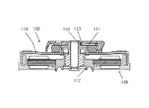
図8において、ディスク回転用モータはロータ部108とステータ部109によって構成されている。ロータ部108のターンテーブル部110には抜け止め部材111が溶接により固定され、この抜け止め部材111が軸受ホルダー112に固定されたロータ部吸引マグネット113のヨ−ク114外周部と軸方向に係合することによってロータ抜け防止機構が構成されている。
In FIG. 8, the disk rotation motor is composed of a
また、ディスク駆動装置は低コスト化への要求も非常に厳しくなっているが、プレス加工によって係合部をロータ部のターンテーブル部に一体に形成された構造も提案されている。(例えば、特許文献3参照)
図9に上記特許文献3に開示された従来技術によるディスク回転用モータの断面図を示す。
Further, the demand for cost reduction of the disk drive device has become very strict. However, a structure in which the engaging portion is integrally formed with the turntable portion of the rotor portion by press working has been proposed. (For example, see Patent Document 3)
FIG. 9 shows a cross-sectional view of a conventional disk rotating motor disclosed in
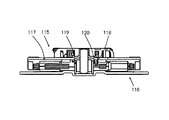
図9においてディスク回転用モータは、ロータ部115とステータ部116によって構成されている。ロータ部115のターンテーブル部117にはロータ抜け防止の係合部118が一体に形成されている。ステータ部116の軸受ホルダーであるメタルハウジング119には螺旋構造120が形成されている。ロータ部115をステータ部116に組み付ける時には、ターンテーブル部117を回転させて係合部118を螺旋構造120に螺号しながら挿入する。係合部118が螺旋構造120から通過した後は、係合部118と螺旋構造120が軸方向に係合するロータ抜け防止機構が構成される。そして、係合部118を螺旋構造120に螺号しながら挿入時とは逆方向にターンテーブル部117を回転させることにより、螺旋構造120から係合部118を通過させてロータ部115をステータ部116から取り外すことができる。これにより、ステータ部116からロータ部の
115挿抜が容易なロータ抜け防止機構が構成できるものである。
In FIG. 9, the disk rotation motor includes a
そして、ディスク駆動用モータの構造をさらに簡素化するため、ターンテーブル部117の係合部118を塑性変形によって折り曲げ、メタルハウジング119の被係合部と係合する構造も提案されている。(例えば、特許文献4参照)
近年、ディスク駆動装置に用いられるディスク回転用モータは、小型化、薄型化、低コスト化が厳しく要求され、さらに数千時間におよぶ長寿命性能、および数万回といったディスクの繰り返し脱着に対する信頼性も要求されている。 In recent years, disk rotation motors used in disk drive devices have been required to be small, thin, and low in cost, and have a long life performance of several thousand hours, and reliability against repeated insertion and removal of disks of several tens of thousands of times. Is also required.
図7に示す抜け防止機構は、ロータ部中央の凹部内に軸受、および抜け止め構造を構成することによって、小型、薄型化しやすいという利点を持つ。しかしながら、被係合部107が形成された弾性部材からなる抜け止め部材106は、軸受ホルダー105に圧入または接着等により固定されているため、数万回というディスク繰り返し脱着に対しての耐久性を考えると好ましくない。また、弾性変形可能な材質および形状を設定する必要があり、材料費も一般の鋼板に比べると高価になる。
The drop prevention mechanism shown in FIG. 7 has an advantage that it is easy to reduce the size and thickness by forming a bearing and a drop prevention structure in the recess in the center of the rotor portion. However, since the retaining
そして、図8に示す抜け防止機構では、抜け止め部材111はターンテーブル部110に溶接により固定されている。防止機構の係合部を弾性変形させて係合させる際、抜け止め部材111をターンテーブル部110から剥離する方向にモ−メントが発生するため、図7に示す抜け防止機構と同様に、数万回というディスク繰り返し脱着に対しての耐久性を考えると好ましくない。
In the drop prevention mechanism shown in FIG. 8, the
また、図7に示す抜け止め構造同様、弾性変形可能な材質および形状を設定する必要があり、材料費も一般の鋼板に比べると高価になる。 Further, like the retaining structure shown in FIG. 7, it is necessary to set a material and a shape that can be elastically deformed, and the material cost is higher than that of a general steel plate.
これに対し、図9に示す抜け止め機構は、抜け止めの係合部118はターンテーブル部117に、被係合部はメタルハウジング119にそれぞれプレス加工によって一体に成形されているため、コスト面で有利になることに加え、一体であるため剛性も高く、耐久性にも優れている。しかしながら、抜け止め構造がターンテーブル部117よりも軸方向下側で構成されるため、薄型化の際の軸受長さ確保という点では不利となる。
On the other hand, the retaining mechanism shown in FIG. 9 is formed integrally with the
上記課題を解決するために本発明は、ディスクを搭載するターンテーブル部が一体に形成されたロータフレームとディスクを芯出し支持するディスク調芯部材と前記ロータフレームに取り付けられたロータマグネットと前記ロータフレームの中央に固定されたシャフトとを有するロータ部と、前記シャフトを支承する軸受とこの軸受を保持するメタルハウジングと前記ロータマグネットと対向して配置され巻線が施されたコアと前記メタルハウジングを保持するブラケットとを備えるステータ部とからなるディスク回転用モータにおいて、前記ロータフレームの内側開口部の中央に前記軸受を収納する凹部が形成され、この凹部内には複数の係合部が前記ロータフレームから一体に径方向内側に突出して形成され、この係合部の軸方向上面部には前記ロータフレームの係合部に対応する位置の少なくとも1箇所に遮蔽片を形成した略円環形状の遮蔽部材が設置され、さらに、前記メタルハウジングの軸方向上側端面には、前記ロータフレームの係合部と同数の切欠部を形成した
被係合部が径方向外側に向かって一体的に形成され、前記ロータフレームの係合部、および前記遮蔽部材の遮蔽片に内接する円の直径寸法は前記メタルハウジングの被係合部の外形寸法より小さく設定され、前記切欠部を含み軸に直行する平面への前記係合部および前記遮蔽片の射影が前記切欠部の範囲内に収まるように構成して、前記係合部と前記遮蔽片の周方向の位相を合わせた状態で前記切欠部を軸方向に通過可能に形成し、前記ロータ部を前記ステータ部に組込んだ状態では、前記係合部と前記切欠部との軸方向の間に前記遮蔽部材が位置するように構成し、前記ロータフレームの係合部と前記遮蔽部材の遮蔽片を周方向に位相をずらすことによって、前記係合部の射影が前記切欠部の範囲内に収まった状態における前記係合部の射影と前記切欠部との周方向の隙間を、前記遮蔽部材の遮蔽片で覆うことでロータ部が容易に抜けない構造とした。
In order to solve the above problems, the present invention provides a rotor frame integrally formed with a turntable portion on which a disk is mounted, a disk alignment member for centering and supporting the disk, a rotor magnet attached to the rotor frame, and the rotor A rotor portion having a shaft fixed at the center of the frame; a bearing for supporting the shaft; a metal housing for holding the bearing; a core disposed opposite to the rotor magnet and provided with winding; and the metal housing In the disk rotation motor comprising a stator portion including a bracket for holding a recess, a recess for housing the bearing is formed in the center of the inner opening of the rotor frame, and a plurality of engagement portions are provided in the recess. An upper surface in the axial direction of this engaging portion that is formed to project radially inward from the rotor frame. Is provided with a substantially annular shielding member formed with a shielding piece at at least one position corresponding to the engaging portion of the rotor frame, and on the axially upper end surface of the metal housing, Engaged portions having the same number of notch portions as the engaging portions are integrally formed radially outward, and the diameter dimension of a circle inscribed in the engaging portion of the rotor frame and the shielding piece of the shielding member Is set to be smaller than the outer dimension of the engaged portion of the metal housing so that the projection of the engaging portion and the shielding piece on the plane including the notch and perpendicular to the shaft is within the range of the notch. In the state where the engaging portion and the shielding piece are aligned in the circumferential direction, the notch portion is formed to be able to pass in the axial direction, and the rotor portion is incorporated in the stator portion, Engagement part and the cut The shielding member is positioned between the axial direction of the portion and the engaging portion of the rotor frame and the shielding piece of the shielding member are shifted in the circumferential direction, thereby projecting the engaging portion. The rotor portion is not easily removed by covering a gap in the circumferential direction between the projection of the engaging portion and the cutout portion in a state of being within the range of the cutout portion with a shielding piece of the shielding member.
本発明によれば、ロータ部とステータ部にそれぞれ形成された抜け止めの係合部、被係合部は、ロータフレーム、およびメタルハウジングにプレス加工によって一体に成形されているため、コスト面で有利になることに加え、一体であるため剛性も高く、耐久性にも優れている。また、ロータフレーム中央の凹形状内に抜け止め構造を構成するため薄型化に有利であることに加え、ロータ部の組込は係合部と被係合部の切欠部との周方向の位相合わせによるため、抜け止め構造に対するストレスはなく、信頼性の高いモータを構成できる。また、遮蔽部材は係合部が被係合部の切欠部の中に収まった場合に、両者の周方向隙間を埋めるだけの機能があればよいため、比較的剛性の低い材料でも可能であるし、ばね性も必要とされないために、非常に安価な材料を使用した抜け止め構造を構成することが可能となる。 According to the present invention, the retaining engagement portion and the engaged portion respectively formed on the rotor portion and the stator portion are integrally formed by pressing on the rotor frame and the metal housing. In addition to being advantageous, since it is integrated, it has high rigidity and excellent durability. In addition, since the retaining structure is formed in the concave shape in the center of the rotor frame, it is advantageous for thinning, and the rotor portion is incorporated in the circumferential phase between the engaging portion and the notched portion of the engaged portion. Due to the matching, there is no stress on the retaining structure, and a highly reliable motor can be configured. In addition, since the shielding member only needs to have a function of filling the circumferential gap between the engaging portions when the engaging portions are accommodated in the cutout portions of the engaged portions, a material with relatively low rigidity is possible. In addition, since the spring property is not required, it is possible to configure a retaining structure using a very inexpensive material.
以下、本発明の実施の形態について図面を参照しながら説明する。 Hereinafter, embodiments of the present invention will be described with reference to the drawings.
(実施の形態)
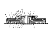
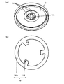
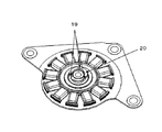
図1は本発明の実施の形態に係るディスク回転用モータの構造断面図、図2(a)は本発明の実施の形態に係るディスク回転用モータのロータ部下側矢視図、図2(b)は本発明の実施の形態に係るディスク回転用モータの遮蔽部材の平面図、図3は本発明の実施の形態に係るディスク回転用モータのステータ部上側矢視図である。
(Embodiment)
FIG. 1 is a structural sectional view of a disk rotation motor according to an embodiment of the present invention, FIG. 2A is a lower side view of a rotor portion of the disk rotation motor according to the embodiment of the present invention, and FIG. ) Is a plan view of the shielding member of the disk rotation motor according to the embodiment of the present invention, and FIG. 3 is a top view of the stator portion of the disk rotation motor according to the embodiment of the present invention.
図1においてディスク回転用モータは、ディスクを搭載するターンテーブル部1が一体に形成されたロータフレーム2と、ディスクを芯出し支持するディスク調芯部材3と、ロータフレーム2に取り付けられたロータマグネット4と、ロータフレーム2の中央に固定されたシャフト5とを有するロータ部6と、シャフト5を支承する軸受7と、この軸受7を保持するメタルハウジング8と、ロータマグネット4と対向して配置され巻線9が施されたコア10と、メタルハウジング8を保持するブラケット11とを備えるステータ部12とにより構成される。
In FIG. 1, a disk rotation motor includes a
ロータ部6は図2(a)に示すように、ロータフレーム2の内側開口部の中央部に凹部13が形成されている。そして、凹部13には、図1に示すように軸受7および軸受7を保持するメタルハウジング8を収納している。また、凹部13内には、ロータ抜け防止の係合部として機能する複数箇所の係合部14が、ロータフレーム2から一体に径方向内側に突出して形成されている。また、この係合部14の軸方向上面部にはロータフレーム2の係合部14に対応する位置に、係合部14と略同形状の遮蔽片15が設置されている。図2(b)に示すように、遮蔽片15は円環部16aにより連結されて遮蔽部材16を形成している。そして遮蔽部材16は、ディスク調芯部材3に形成された押圧ばね部17によって円環部16aをロータフレーム2の外側天面に軸方向に圧接固定され、さらにディスク調芯部材3に形成された支柱形状部18によってロータフレームに対する回転移動を
防止されている。
As shown in FIG. 2A, the rotor portion 6 has a
また、図3に示すように、ステータ部12のメタルハウジング8の軸方向上側端面には、ロータフレーム2の係合部14と同数の切欠部19を形成した被係合部20が径方向外側に向かって一体的に形成されている。
Further, as shown in FIG. 3, an engaged
そしてロータフレーム2の係合部14、および遮蔽部材16の遮蔽片15に内接する円の直径寸法は、メタルハウジング8の被係合部20の外径寸法より小さく設定されている。
The diameter of the circle inscribed in the engaging
さらに、メタルハウジング8の切欠部19は、ロータフレーム2の係合部14および遮蔽部材16の遮蔽片15が軸方向に挿通可能な大きさ及び形状に形成されている。即ち、切欠部19を含み軸に直行する平面へのロータフレーム2の係合部14および遮蔽部材16の遮蔽片15の射影が、切欠部19の範囲内に収まる様に形成されている。
Further, the
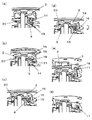
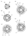
図4(a)〜(f)は本発明の実施の形態に係る抜け止め係合過程の概略を示す斜視図である。また、図5(a)〜(e)は、それぞれ図4(a)〜(f)に示す状態の要部横断面図である。 4 (a) to 4 (f) are perspective views showing an outline of a retaining engagement process according to the embodiment of the present invention. FIGS. 5A to 5E are cross-sectional views of main parts in the states shown in FIGS. 4A to 4F, respectively.
図4(a)に示すように、ロータ部6をステータ部12に挿入する際には、メタルハウジング8の切欠部19を含み軸に直行する平面へのロータフレーム2の係合部14の射影が、図5(a)に斜線で示す切欠部19の範囲内に収まる様に周方向の位置を合わせて、係合部14を軸方向に挿通させることによって、係合部14を被係合部20の軸方向下側に向かって貫通させることができる。この状態では、図5(b)に示すように、切欠部19と係合部14の射影の間には周方向の隙間wが生じる。次に、図4(b)に示すように、ロータフレーム2の係合部14がメタルハウジング8の被係合部20を貫通した後、図5(c)に示すようにメタルハウジング8の切欠部19を含み軸に直行する平面への遮蔽部材16の遮蔽片15の射影が、図5(a)に斜線で示す切欠部19の範囲内に収まる様に周方向の位置を合わせる。この状態で遮蔽片15を軸方向に挿通させることによって、図4(c)に示すように、遮蔽片15を被係合部20の軸方向下側に向かって貫通させることができる。
As shown in FIG. 4A, when the rotor portion 6 is inserted into the
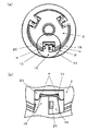
遮蔽部材16の遮蔽片15がメタルハウジング8の被係合部20を貫通した後、図4(d)、図5(d)に示すように、メタルハウジング8の被係合部20に形成された切欠部19とロータフレーム2の係合部14の射影の周方向の隙間wを覆う位置まで遮蔽部材16を周方向に(図中矢印で示す)回転移動させる。その後、図4(e)に示すように、ロータフレーム2にディスク調芯部材3を挿入固定する。図6(a)にロータフレーム2にディスク調芯部材3が挿入固定された状態の上側斜視図を示す。図6(a)にPで示す要部の部分拡大図を図6(b)に示す。遮蔽部材16を周方向に回転移動させることにより、メタルハウジング8の被係合部20に形成された切欠部19とロータフレーム2の係合部14の射影の周方向の隙間wの内、回転方向側の隙間wが、遮蔽片15で覆われている。
After the
また、図4(e)に示すように、ディスク調芯部材3には、遮蔽部材16の遮蔽片15に対応する位置に、ロータフレーム2の天面に向けて支柱形状部18が突出して形成されており、ロータフレーム2にディスク調芯部材3を挿入固定する際に、図5(e)に示すように、支柱形状部18を遮蔽部材16の遮蔽片15の周方向の端面に当接させることによって、遮蔽部材16の遮蔽片15のロータフレーム2に対する回転移動を抑制し、上記隙間wを覆う状態が確実に維持できるように構成されている。さらに、ディスク調芯部材3には、図4(e)に示すように、遮蔽部材16の円環部16aに対応する位置に弾性を
有する押圧ばね部17が形成されており、この押圧ばね部17により遮蔽部材16を円環部16aの位置でロータフレーム2の外側天面に軸方向に圧接固定することによって、軸方向のがたつきを抑制するように構成されている。そして、図4(b)、図5(b)に示すように、ロータフレーム2の係合部14に、軸方向上側に突出して凸部21を形成し、図5(d)に示すように、この凸部21に遮蔽部材16の遮蔽片15の周方向の端面を当接させることにより、ディスク調芯部材3を挿入するまでの作業工程において、遮蔽部材16の周方向ずれを抑制し、上記隙間wを覆う状態を確実に維持することができる。
Further, as shown in FIG. 4 (e), the
以上の状態で、ロータ部6を軸方向上側に移動させた場合、ロータフレーム2の係合部14とメタルハウジング8の被係合部20が係合してロータ部6の移動を規制するので、抜け防止機構として機能する。仮に被係合部20の切欠部19を含み軸に直行する平面への係合部14の射影が、切欠部19の範囲内に収まる状態となっても、係合部14の射影と切欠部19との隙間を、係合部14と切欠部19の間に配設された遮蔽部材16の遮蔽片15が塞ぐので、ロータ部6が容易には抜けない構造となる。
In the above state, when the rotor part 6 is moved upward in the axial direction, the engaging
本実施の形態においては、遮蔽部材16の遮蔽片15は、ロータフレーム2の係合部14と同数形成されているが、それよりも少数であっても機能を果たすことは可能である。
In the present embodiment, the same number of the shielding
また、遮蔽部材16のストレス低減や破損防止、またロータ部6の抜け強度の確保を考えた場合、図4(d)に示す、ロータフレーム2の係合部14の射影が切欠部19の範囲内に収まる状態における切欠部19と係合部14の射影の周方向隙間wは可能な限り狭い方が良いが、少なくとも遮蔽部材16の板厚よりも小さい方が望ましい。
Further, in consideration of stress reduction and prevention of breakage of the shielding
なお、遮蔽部材16については、金属製薄肉板でも可能であるし、樹脂成形部材等であってもロータフレーム2の係合部14とメタルハウジング8の被係合部20の切欠部19の周方向隙間wを塞ぐことができる材料、および形状であれば代用は可能である。
The shielding
光メディア用スピンドルモータ等、小型化、薄型化に加え、高信頼性や、低コストが求められるモバイル機器用ブラシレスモータに有用である。 It is useful for brushless motors for mobile devices that require high reliability and low cost in addition to miniaturization and thinning, such as optical media spindle motors.
1、103、110、117 ターンテーブル部
2 ロータフレーム
3 ディスク調芯部材
4 ロータマグネット
5 シャフト
6、101、108、115 ロータ部
7 軸受
8、119 メタルハウジング
9 巻線
10 コア
11 ブラケット
12、102、109、116 ステータ部
13 凹部
14、104、118 係合部
15 遮蔽片
16 遮蔽部材
16a 円環部
17 押圧ばね部
18 支柱形状部
19 切欠部
20、107 被係合部
21 凸部
105、112 軸受ホルダー
106、111 抜け止め部材
113 吸引マグネット
114 ヨ−ク
120 螺旋構造
DESCRIPTION OF SYMBOLS 1,103,110,117
Claims (5)
Priority Applications (1)
| Application Number | Priority Date | Filing Date | Title |
|---|---|---|---|
| JP2008315367A JP5575389B2 (en) | 2008-12-11 | 2008-12-11 | Disc rotation motor |
Applications Claiming Priority (1)
| Application Number | Priority Date | Filing Date | Title |
|---|---|---|---|
| JP2008315367A JP5575389B2 (en) | 2008-12-11 | 2008-12-11 | Disc rotation motor |
Publications (2)
| Publication Number | Publication Date |
|---|---|
| JP2010142011A true JP2010142011A (en) | 2010-06-24 |
| JP5575389B2 JP5575389B2 (en) | 2014-08-20 |
Family
ID=42351627
Family Applications (1)
| Application Number | Title | Priority Date | Filing Date |
|---|---|---|---|
| JP2008315367A Expired - Fee Related JP5575389B2 (en) | 2008-12-11 | 2008-12-11 | Disc rotation motor |
Country Status (1)
| Country | Link |
|---|---|
| JP (1) | JP5575389B2 (en) |
Cited By (1)
| Publication number | Priority date | Publication date | Assignee | Title |
|---|---|---|---|---|
| CN103795173A (en) * | 2012-10-31 | 2014-05-14 | 日本电产三协株式会社 | Motor |
Citations (2)
| Publication number | Priority date | Publication date | Assignee | Title |
|---|---|---|---|---|
| JP2006325333A (en) * | 2005-05-19 | 2006-11-30 | Matsushita Electric Ind Co Ltd | Disk drive |
| JP2008182830A (en) * | 2007-01-25 | 2008-08-07 | Nippon Densan Corp | Brushless motor, disk drive |
-
2008
- 2008-12-11 JP JP2008315367A patent/JP5575389B2/en not_active Expired - Fee Related
Patent Citations (2)
| Publication number | Priority date | Publication date | Assignee | Title |
|---|---|---|---|---|
| JP2006325333A (en) * | 2005-05-19 | 2006-11-30 | Matsushita Electric Ind Co Ltd | Disk drive |
| JP2008182830A (en) * | 2007-01-25 | 2008-08-07 | Nippon Densan Corp | Brushless motor, disk drive |
Cited By (1)
| Publication number | Priority date | Publication date | Assignee | Title |
|---|---|---|---|---|
| CN103795173A (en) * | 2012-10-31 | 2014-05-14 | 日本电产三协株式会社 | Motor |
Also Published As
| Publication number | Publication date |
|---|---|
| JP5575389B2 (en) | 2014-08-20 |
Similar Documents
| Publication | Publication Date | Title |
|---|---|---|
| KR100998778B1 (en) | Chucking device, brushless motor with the chucking device and disk drive apparatus with the brushless motor | |
| JP5092420B2 (en) | Brushless motor, disk drive | |
| JP4978257B2 (en) | Motor equipped with chucking device, and disk drive equipped with this motor | |
| JP2008234735A (en) | Motor with chucking device, and disk drive device mounting the motor | |
| JP2007166799A (en) | Inner rotor type brushless motor | |
| JP2008092706A (en) | Brushless motor and disk drive unit mounting it | |
| JP4493549B2 (en) | Brushless motor | |
| JP5777876B2 (en) | Brushless motor and disk drive device | |
| JP5575389B2 (en) | Disc rotation motor | |
| US8836182B2 (en) | Disk drive motor | |
| KR101039225B1 (en) | Spindle motor and clamper | |
| JP5186335B2 (en) | Disc rotation motor | |
| KR20110018541A (en) | Spindle motor with a chuck member, capable of having structure in which a chucking arm is integrated with an elastic spring | |
| JP5226499B2 (en) | Disc rotation motor | |
| JP5226487B2 (en) | Disc rotation motor | |
| US20060206909A1 (en) | Thin brushless motor | |
| JP5373362B2 (en) | Disc rotation motor | |
| JP2008181622A (en) | Spindle motor and information recorder using the same | |
| US20110167438A1 (en) | Single Body Type Bracket and Spindle Motor Structure Having the Same | |
| JP5869795B2 (en) | Spindle motor | |
| JP2011067083A (en) | Motor, recording disk drive apparatus, and motor manufacturing method | |
| JP2008312300A (en) | Spindle motor | |
| US8963390B2 (en) | Spindle motor and disc drive device | |
| JP2000251361A (en) | Disk driving device | |
| JP5778013B2 (en) | Spindle motor and disc clamp mechanism |
Legal Events
| Date | Code | Title | Description |
|---|---|---|---|
| A711 | Notification of change in applicant |
Free format text: JAPANESE INTERMEDIATE CODE: A711 Effective date: 20110407 |
|
| RD02 | Notification of acceptance of power of attorney |
Free format text: JAPANESE INTERMEDIATE CODE: A7422 Effective date: 20110407 |
|
| A621 | Written request for application examination |
Free format text: JAPANESE INTERMEDIATE CODE: A621 Effective date: 20111110 |
|
| A977 | Report on retrieval |
Free format text: JAPANESE INTERMEDIATE CODE: A971007 Effective date: 20130313 |
|
| A131 | Notification of reasons for refusal |
Free format text: JAPANESE INTERMEDIATE CODE: A131 Effective date: 20130319 |
|
| A711 | Notification of change in applicant |
Free format text: JAPANESE INTERMEDIATE CODE: A712 Effective date: 20130424 |
|
| A131 | Notification of reasons for refusal |
Free format text: JAPANESE INTERMEDIATE CODE: A131 Effective date: 20131126 |
|
| A521 | Request for written amendment filed |
Free format text: JAPANESE INTERMEDIATE CODE: A523 Effective date: 20140110 |
|
| TRDD | Decision of grant or rejection written | ||
| A01 | Written decision to grant a patent or to grant a registration (utility model) |
Free format text: JAPANESE INTERMEDIATE CODE: A01 Effective date: 20140603 |
|
| A61 | First payment of annual fees (during grant procedure) |
Free format text: JAPANESE INTERMEDIATE CODE: A61 Effective date: 20140702 |
|
| R150 | Certificate of patent or registration of utility model |
Ref document number: 5575389 Country of ref document: JP Free format text: JAPANESE INTERMEDIATE CODE: R150 |
|
| R250 | Receipt of annual fees |
Free format text: JAPANESE INTERMEDIATE CODE: R250 |
|
| R250 | Receipt of annual fees |
Free format text: JAPANESE INTERMEDIATE CODE: R250 |
|
| R250 | Receipt of annual fees |
Free format text: JAPANESE INTERMEDIATE CODE: R250 |
|
| S533 | Written request for registration of change of name |
Free format text: JAPANESE INTERMEDIATE CODE: R313533 |
|
| R350 | Written notification of registration of transfer |
Free format text: JAPANESE INTERMEDIATE CODE: R350 |
|
| R250 | Receipt of annual fees |
Free format text: JAPANESE INTERMEDIATE CODE: R250 |
|
| LAPS | Cancellation because of no payment of annual fees |