JP2010142001A - Charge monitoring device - Google Patents
Charge monitoring device Download PDFInfo
- Publication number
- JP2010142001A JP2010142001A JP2008314815A JP2008314815A JP2010142001A JP 2010142001 A JP2010142001 A JP 2010142001A JP 2008314815 A JP2008314815 A JP 2008314815A JP 2008314815 A JP2008314815 A JP 2008314815A JP 2010142001 A JP2010142001 A JP 2010142001A
- Authority
- JP
- Japan
- Prior art keywords
- vehicle
- information
- power supply
- power
- supply facility
- Prior art date
- Legal status (The legal status is an assumption and is not a legal conclusion. Google has not performed a legal analysis and makes no representation as to the accuracy of the status listed.)
- Granted
Links
Images

Classifications
-
- G—PHYSICS
- G07—CHECKING-DEVICES
- G07C—TIME OR ATTENDANCE REGISTERS; REGISTERING OR INDICATING THE WORKING OF MACHINES; GENERATING RANDOM NUMBERS; VOTING OR LOTTERY APPARATUS; ARRANGEMENTS, SYSTEMS OR APPARATUS FOR CHECKING NOT PROVIDED FOR ELSEWHERE
- G07C5/00—Registering or indicating the working of vehicles
- G07C5/08—Registering or indicating performance data other than driving, working, idle, or waiting time, with or without registering driving, working, idle or waiting time
- G07C5/0841—Registering performance data
- G07C5/085—Registering performance data using electronic data carriers
-
- B—PERFORMING OPERATIONS; TRANSPORTING
- B60—VEHICLES IN GENERAL
- B60L—PROPULSION OF ELECTRICALLY-PROPELLED VEHICLES; SUPPLYING ELECTRIC POWER FOR AUXILIARY EQUIPMENT OF ELECTRICALLY-PROPELLED VEHICLES; ELECTRODYNAMIC BRAKE SYSTEMS FOR VEHICLES IN GENERAL; MAGNETIC SUSPENSION OR LEVITATION FOR VEHICLES; MONITORING OPERATING VARIABLES OF ELECTRICALLY-PROPELLED VEHICLES; ELECTRIC SAFETY DEVICES FOR ELECTRICALLY-PROPELLED VEHICLES
- B60L53/00—Methods of charging batteries, specially adapted for electric vehicles; Charging stations or on-board charging equipment therefor; Exchange of energy storage elements in electric vehicles
- B60L53/10—Methods of charging batteries, specially adapted for electric vehicles; Charging stations or on-board charging equipment therefor; Exchange of energy storage elements in electric vehicles characterised by the energy transfer between the charging station and the vehicle
- B60L53/14—Conductive energy transfer
-
- B—PERFORMING OPERATIONS; TRANSPORTING
- B60—VEHICLES IN GENERAL
- B60L—PROPULSION OF ELECTRICALLY-PROPELLED VEHICLES; SUPPLYING ELECTRIC POWER FOR AUXILIARY EQUIPMENT OF ELECTRICALLY-PROPELLED VEHICLES; ELECTRODYNAMIC BRAKE SYSTEMS FOR VEHICLES IN GENERAL; MAGNETIC SUSPENSION OR LEVITATION FOR VEHICLES; MONITORING OPERATING VARIABLES OF ELECTRICALLY-PROPELLED VEHICLES; ELECTRIC SAFETY DEVICES FOR ELECTRICALLY-PROPELLED VEHICLES
- B60L53/00—Methods of charging batteries, specially adapted for electric vehicles; Charging stations or on-board charging equipment therefor; Exchange of energy storage elements in electric vehicles
- B60L53/30—Constructional details of charging stations
- B60L53/305—Communication interfaces
-
- H—ELECTRICITY
- H04—ELECTRIC COMMUNICATION TECHNIQUE
- H04B—TRANSMISSION
- H04B2203/00—Indexing scheme relating to line transmission systems
- H04B2203/54—Aspects of powerline communications not already covered by H04B3/54 and its subgroups
- H04B2203/5429—Applications for powerline communications
- H04B2203/5458—Monitor sensor; Alarm systems
-
- Y—GENERAL TAGGING OF NEW TECHNOLOGICAL DEVELOPMENTS; GENERAL TAGGING OF CROSS-SECTIONAL TECHNOLOGIES SPANNING OVER SEVERAL SECTIONS OF THE IPC; TECHNICAL SUBJECTS COVERED BY FORMER USPC CROSS-REFERENCE ART COLLECTIONS [XRACs] AND DIGESTS
- Y02—TECHNOLOGIES OR APPLICATIONS FOR MITIGATION OR ADAPTATION AGAINST CLIMATE CHANGE
- Y02T—CLIMATE CHANGE MITIGATION TECHNOLOGIES RELATED TO TRANSPORTATION
- Y02T10/00—Road transport of goods or passengers
- Y02T10/60—Other road transportation technologies with climate change mitigation effect
- Y02T10/70—Energy storage systems for electromobility, e.g. batteries
-
- Y—GENERAL TAGGING OF NEW TECHNOLOGICAL DEVELOPMENTS; GENERAL TAGGING OF CROSS-SECTIONAL TECHNOLOGIES SPANNING OVER SEVERAL SECTIONS OF THE IPC; TECHNICAL SUBJECTS COVERED BY FORMER USPC CROSS-REFERENCE ART COLLECTIONS [XRACs] AND DIGESTS
- Y02—TECHNOLOGIES OR APPLICATIONS FOR MITIGATION OR ADAPTATION AGAINST CLIMATE CHANGE
- Y02T—CLIMATE CHANGE MITIGATION TECHNOLOGIES RELATED TO TRANSPORTATION
- Y02T10/00—Road transport of goods or passengers
- Y02T10/60—Other road transportation technologies with climate change mitigation effect
- Y02T10/7072—Electromobility specific charging systems or methods for batteries, ultracapacitors, supercapacitors or double-layer capacitors
-
- Y—GENERAL TAGGING OF NEW TECHNOLOGICAL DEVELOPMENTS; GENERAL TAGGING OF CROSS-SECTIONAL TECHNOLOGIES SPANNING OVER SEVERAL SECTIONS OF THE IPC; TECHNICAL SUBJECTS COVERED BY FORMER USPC CROSS-REFERENCE ART COLLECTIONS [XRACs] AND DIGESTS
- Y02—TECHNOLOGIES OR APPLICATIONS FOR MITIGATION OR ADAPTATION AGAINST CLIMATE CHANGE
- Y02T—CLIMATE CHANGE MITIGATION TECHNOLOGIES RELATED TO TRANSPORTATION
- Y02T90/00—Enabling technologies or technologies with a potential or indirect contribution to GHG emissions mitigation
- Y02T90/10—Technologies relating to charging of electric vehicles
- Y02T90/12—Electric charging stations
-
- Y—GENERAL TAGGING OF NEW TECHNOLOGICAL DEVELOPMENTS; GENERAL TAGGING OF CROSS-SECTIONAL TECHNOLOGIES SPANNING OVER SEVERAL SECTIONS OF THE IPC; TECHNICAL SUBJECTS COVERED BY FORMER USPC CROSS-REFERENCE ART COLLECTIONS [XRACs] AND DIGESTS
- Y02—TECHNOLOGIES OR APPLICATIONS FOR MITIGATION OR ADAPTATION AGAINST CLIMATE CHANGE
- Y02T—CLIMATE CHANGE MITIGATION TECHNOLOGIES RELATED TO TRANSPORTATION
- Y02T90/00—Enabling technologies or technologies with a potential or indirect contribution to GHG emissions mitigation
- Y02T90/10—Technologies relating to charging of electric vehicles
- Y02T90/14—Plug-in electric vehicles
-
- Y—GENERAL TAGGING OF NEW TECHNOLOGICAL DEVELOPMENTS; GENERAL TAGGING OF CROSS-SECTIONAL TECHNOLOGIES SPANNING OVER SEVERAL SECTIONS OF THE IPC; TECHNICAL SUBJECTS COVERED BY FORMER USPC CROSS-REFERENCE ART COLLECTIONS [XRACs] AND DIGESTS
- Y02—TECHNOLOGIES OR APPLICATIONS FOR MITIGATION OR ADAPTATION AGAINST CLIMATE CHANGE
- Y02T—CLIMATE CHANGE MITIGATION TECHNOLOGIES RELATED TO TRANSPORTATION
- Y02T90/00—Enabling technologies or technologies with a potential or indirect contribution to GHG emissions mitigation
- Y02T90/10—Technologies relating to charging of electric vehicles
- Y02T90/16—Information or communication technologies improving the operation of electric vehicles
Landscapes
- Engineering & Computer Science (AREA)
- Power Engineering (AREA)
- Transportation (AREA)
- Mechanical Engineering (AREA)
- Physics & Mathematics (AREA)
- General Physics & Mathematics (AREA)
- Electric Propulsion And Braking For Vehicles (AREA)
- Charge And Discharge Circuits For Batteries Or The Like (AREA)
- Secondary Cells (AREA)
Abstract
Description
本発明は、例えば電気自動車やハイブリッドカーのような車両に搭載されるバッテリを充電する動作を監視するための充電監視装置に関する。 The present invention relates to a charge monitoring device for monitoring an operation of charging a battery mounted on a vehicle such as an electric vehicle or a hybrid car.
例えば近年の自動車業界においては、二酸化炭素の排出削減やエネルギーの効率的な利用の観点から、電気のみをエネルギーとして利用し走行する電気自動車や、エンジンと電気モータとの両方を搭載したハイブリッドカーが実用化されている。一般的なハイブリッドカーにおいては、車両が減速する際に運動エネルギーを電気エネルギーに変換して回収してバッテリに充電し、回収した電気エネルギーを走行時に利用してガソリン等の燃料の消費を抑制する。しかし、減速する際の運動エネルギーを回収するだけでは、燃料の消費を抑制する効果が小さく、二酸化炭素の削減効果も小さい。 For example, in the automobile industry in recent years, from the viewpoint of reducing carbon dioxide emissions and using energy efficiently, there are electric cars that run using only electricity as energy, and hybrid cars equipped with both an engine and an electric motor. It has been put into practical use. In a typical hybrid car, when the vehicle decelerates, kinetic energy is converted to electric energy and collected to charge the battery, and the collected electric energy is used during driving to suppress fuel consumption such as gasoline. . However, merely recovering the kinetic energy during deceleration reduces the effect of suppressing fuel consumption and the effect of reducing carbon dioxide.
そこで、二酸化炭素の削減効果を高めるためにプラグインハイブリッドカー(プラグインHV)が開発されている。プラグインハイブリッドカーは、自動車側に設置したプラグを家庭用の電源コンセント等に差し込むことにより、家庭用の電源(商用交流電源:AC100V等)から自動車側のバッテリに充電する機能を備えている。従って、減速の際に回収可能な運動エネルギーの他に、家庭用の電源から充電によって得た電気エネルギーを自動車の走行に利用することができるので、電気モータの使用頻度を高めて燃料の消費を抑制すると共に、効率の高い電気モータを高い頻度で使用して二酸化炭素の削減効果を高めることが可能になる。 Therefore, a plug-in hybrid car (plug-in HV) has been developed to increase the carbon dioxide reduction effect. The plug-in hybrid car has a function of charging a battery on the automobile side from a household power supply (commercial AC power supply: AC 100 V, etc.) by inserting a plug installed on the automobile side into a household power outlet or the like. Therefore, in addition to the kinetic energy that can be recovered at the time of deceleration, the electric energy obtained by charging from a household power source can be used for driving the automobile, so the frequency of use of the electric motor can be increased to reduce fuel consumption. It is possible to increase the reduction effect of carbon dioxide by using an electric motor with high efficiency at a high frequency.
一方、自動車に関して排出する二酸化炭素の削減効果を高めるためには、経済的な運転を行うことも非常に有効である。例えば、自動車の運転中に急加速を行う場合のように短時間で大量の燃料消費を伴うような運転をやめることにより、燃料消費を抑制し二酸化炭素の削減効果を高めることができる。 On the other hand, in order to increase the reduction effect of carbon dioxide emitted from automobiles, it is very effective to perform economical driving. For example, by stopping driving that consumes a large amount of fuel in a short time, such as when sudden acceleration is performed while driving a car, fuel consumption can be suppressed and the carbon dioxide reduction effect can be enhanced.
また、自動車に関して運転者が経済的な運転を行うために利用可能な技術として、従来よりタコグラフやナビゲーション装置が実用化され利用されている。 In addition, tachographs and navigation devices have been put into practical use and used as techniques that can be used for drivers to drive economically with respect to automobiles.
タコグラフは、自動車の運転中の状態を表す車速やエンジン回転数などの情報を定期的に取得し時系列情報として記録する。従って、例えばタクシー会社や運送会社などの事業者においては、タコグラフによって記録された時系列情報を参照し分析することにより、各車両の運転者が経済的な運転を行っているか否かを知ることができ、二酸化炭素の削減効果を高めるために役立てることができる。 The tachograph periodically acquires information such as a vehicle speed and an engine speed representing a driving state of the automobile and records it as time series information. Therefore, for example, in a taxi company or a shipping company, it is possible to know whether the driver of each vehicle is driving economically by referring to and analyzing the time series information recorded by the tachograph. Can be used to increase the carbon dioxide reduction effect.
また、ナビゲーション装置は、それを搭載した車両の現在位置を測定して現在位置の近傍に関する地図情報を画面上に表示したり、現在位置から目的地までの走行予定ルートを自動的に決定したり、渋滞状況を表す情報、事故の発生状況を表す情報など最新の交通情報を取得して走行予定ルートの変更などに反映することもできる。ナビゲーション装置を利用することにより、例えば最短の経路を通るように走行予定ルートを決定したり、渋滞箇所や事故発生箇所を避けるように走行予定ルートを変更することもできるので、二酸化炭素の削減効果を高めるために役立てることができる。 In addition, the navigation device measures the current position of the vehicle on which it is mounted, displays map information about the vicinity of the current position on the screen, and automatically determines the planned travel route from the current position to the destination. It is also possible to acquire the latest traffic information such as information indicating the traffic congestion status and the information indicating the occurrence of the accident and to reflect it in the change of the planned travel route. By using a navigation device, for example, it is possible to determine the planned travel route so as to pass the shortest route, or to change the planned travel route so as to avoid traffic congestion points and accident occurrence points, so carbon dioxide reduction effect Can help to increase.
しかし、実際にタコグラフを使用する場合には、例えばタクシー会社や運送会社などの事業者において管理者が各車両の運行状況を把握するためには、各車両に搭載されたタコグラフからそれに蓄積されている大量の情報を取り出してこの情報を管理者側の装置(例えばパーソナルコンピュータ)上に転送しなければならない。 However, when the tachograph is actually used, for example, in an operator such as a taxi company or a transportation company, in order for the manager to grasp the operation status of each vehicle, it is accumulated from the tachograph mounted on each vehicle. A large amount of information must be taken out and transferred to an administrator's device (for example, a personal computer).
車載装置であるタコグラフから管理者側の装置に対して情報を転送するための従来技術については、例えば特許文献1に開示されている。特許文献1においては、パケット通信が可能な無線通信インタフェースを利用したり、脱着自在なメモリカードを利用して情報を転送することを提案している。
For example,
一方、ナビゲーション装置を利用する場合には、例えば最適な走行予定ルートを決定するために、常に最新の地図情報等が必要になる。例えば、走行予定ルート上に含まれる渋滞箇所を回避可能な新しい道路が完成しているにもかかわらず、新しい道路の情報が反映されていない古い地図情報を利用している場合には、渋滞箇所を回避できないので二酸化炭素の削減効果を十分に高めることができない。 On the other hand, when using a navigation device, for example, the latest map information or the like is always required in order to determine an optimal travel schedule route. For example, if a new road that can avoid a traffic jam location included in the planned route is completed, but you are using old map information that does not reflect the new road information, Therefore, the carbon dioxide reduction effect cannot be enhanced sufficiently.
自動車用のナビゲーション装置を利用する場合には、従来より、例えばCD(コンパクトディスク)やDVDのような脱着自在な情報記録媒体を利用して、あるいはモバイルパケット通信などを利用して車載装置であるナビゲーション装置が使用する地図情報などを最新の情報に更新することが一般的に行われている。また、例えば特許文献2に開示された従来技術においては、地図データの更新の際に通信により転送するデータ量を削減するために、差分データの利用を可能にしている。
しかしながら、例えば車載装置であるタコグラフから車外の管理装置に対してデータを転送するために公共の無線通信網を利用する場合には、データ量が増えるとパケット料金などの通信コストが嵩むという問題があるし、セキュリティの問題も発生する。また、メモリカードなどの脱着可能な記録媒体を利用してデータを転送する場合には、メモリカードの遺失により情報が第三者に漏洩したり、メモリカードの物理的な破損によって蓄積された重要なデータが消滅する可能性もある。 However, for example, when a public wireless communication network is used to transfer data from a tachograph that is an in-vehicle device to a management device outside the vehicle, there is a problem that communication costs such as packet charges increase as the amount of data increases. There are also security issues. In addition, when transferring data using a removable recording medium such as a memory card, information leaked to a third party due to the loss of the memory card, or accumulated due to physical damage to the memory card Data may disappear.
同様に、ナビゲーション装置を利用する場合にも、それが使用する地図などのデータベースを最新の情報に更新する際に、公共の無線通信網を利用すると通信コストが嵩むという問題がある。また、CDやDVDのような脱着自在な情報記録媒体を利用してデータベースを更新する場合には、これらの専用の情報記録媒体からデータを読み取るために読み取り装置(DVDドライブなど)が必要になるし、情報記録媒体が物理的に破損する可能性もある。 Similarly, when a navigation device is used, there is a problem that communication costs increase if a public wireless communication network is used when updating a database such as a map used by the navigation device to the latest information. In addition, when a database is updated using a removable information recording medium such as a CD or DVD, a reading device (DVD drive or the like) is required to read data from these dedicated information recording media. In addition, the information recording medium may be physically damaged.
本発明は、上述した事情に鑑みてなされたものであり、その目的は、充電が可能な電気自動車やプラグインハイブリッドカーの上でタコグラフやナビゲーション装置の機能を利用する場合に、情報の転送に伴う通信コスト等の負担を軽減することが可能な充電監視装置を提供することにある。 The present invention has been made in view of the above-described circumstances, and its purpose is to transfer information when using a function of a tachograph or a navigation device on an electric vehicle or a plug-in hybrid car that can be charged. An object of the present invention is to provide a charge monitoring device capable of reducing the burden of accompanying communication costs and the like.
前述した目的を達成するために、本発明に係る充電監視装置は、下記(1)〜(7)を特徴としている。
(1) 充電可能なバッテリを搭載し、該バッテリから供給される電力を走行のために利用可能な車両に対して、搭載もしくは接続可能に構成され、前記車両とは別体に設けられた外部電源設備から前記車両上のバッテリへの電力の供給を監視する充電監視装置であって、
特定の車両に固有に割り当てられた車両側識別情報を保持する車両ID保持部と、
充電のための電力が現れる電源ラインと接続され、前記電源ラインを信号の伝送路として利用し、前記外部電源設備側の電源ラインに接続される車両外装置との間で情報を交換可能な電力線通信部と、
前記車両上で生成された情報を蓄積する車両側情報蓄積部と、
前記車両と前記外部電源設備とが接続され前記外部電源設備から供給される電力を利用して車両上のバッテリーを充電する際に、前記電力線通信部を経由して前記車両外装置との間で通信を行い、前記車両ID保持部が保持している車両側識別情報を前記車両外装置に送信すると共に、所定の条件を満たす場合には、前記車両側情報蓄積部が蓄積している情報を前記車両外装置に送信する通信制御部と
を設けたことを特徴とする。
(2) 前記(1)に記載の充電監視装置において、
前記車両側情報蓄積部として、少なくとも車両の速度及びエンジンの回転数の情報を蓄積するタコグラフの機能を搭載した
ことを特徴とする。
(3) 前記(1)に記載の充電監視装置において、
前記車両側情報蓄積部として、少なくとも地図情報を保持すると共に車両の現在位置を測定し現在位置を含む地図を表示するナビゲーションの機能を搭載した
ことを特徴とする。
(4) 前記(2)又は(3)のいずれかに記載の充電監視装置において、
前記車両と前記外部電源設備とが接続され前記外部電源設備から供給される電力を利用して車両上のバッテリーを充電する際に、前記車両外装置から送出される情報を前記電力線通信部を経由して受信し、受信した情報を用いて前記車両側情報蓄積部が保持している情報の内容を更新する情報更新制御部
を更に設けたことを特徴とする。
(5) 前記(1)に記載の充電監視装置において、
前記通信制御部は、前記車両と前記外部電源設備とが接続され前記外部電源設備から供給される電力を利用して車両上のバッテリーを充電する際に、前記車両外装置から送出される情報を前記電力線通信部を経由して受信し、受信した情報の中に含まれる前記車両外装置を表す接続先識別情報を検出し、前記接続先識別情報を予め登録されている情報と比較し、一致する場合に限り前記車両側情報蓄積部が蓄積している情報を前記車両外装置に送信する
ことを特徴とする。
(6) 充電可能なバッテリを搭載し、該バッテリから供給される電力を走行のために利用可能な車両との間で所定の電源ラインを介して接続可能に構成され、前記車両とは別体に設けられた外部電源設備から前記車両上のバッテリへの電力の供給を監視するために、前記外部電源設備側に接続可能な充電監視装置であって、
特定の外部電源設備に固有に割り当てられた電源側識別情報を保持する電源ID保持部と、
前記外部電源設備の電源ラインと接続され、前記電源ラインを信号の伝送路として利用し、前記外部電源設備の電源ラインに接続される車両上の通信装置との間で情報を交換可能な電力線通信部と、
前記車両と前記外部電源設備とが接続され前記外部電源設備から供給される電力を利用して車両上のバッテリーを充電する際に、前記電力線通信部を経由して前記車両上の通信装置との間で通信を行い、前記電源ID保持部が保持している電源側識別情報を前記車両側に送信すると共に、前記車両側が送信する情報を前記電力線通信部を経由して受信し、受信した情報を保存する電源側受信制御部と
を設けたことを特徴とする。
(7) 前記(6)に記載の充電監視装置において、
少なくとも地図を含む最新の情報を逐次取得し最新の情報を保持する地図情報保持部と、
前記車両と前記外部電源設備とが接続され前記外部電源設備から供給される電力を利用して車両上のバッテリーを充電する際に、前記電力線通信部を経由して前記車両上の通信装置との間で通信を行い、前記地図情報保持部が保持している最新の情報を前記電力線通信部を経由して車両側に送信する電源側送信制御部と
を更に設けたことを特徴とする。
In order to achieve the above-described object, a charge monitoring apparatus according to the present invention is characterized by the following (1) to (7).
(1) An external battery mounted with a rechargeable battery and configured to be mountable or connectable to a vehicle that can use electric power supplied from the battery for traveling. A charge monitoring device for monitoring power supply from a power supply facility to a battery on the vehicle,
A vehicle ID holding unit for holding vehicle-side identification information uniquely assigned to a specific vehicle;
A power line that is connected to a power line on which power for charging appears, and that can exchange information with a device outside the vehicle that is connected to the power line on the external power facility side, using the power line as a signal transmission path A communication department;
A vehicle-side information storage unit for storing information generated on the vehicle;
When the vehicle and the external power supply facility are connected and the battery on the vehicle is charged using the power supplied from the external power supply facility, between the vehicle external device via the power line communication unit When communication is performed and the vehicle-side identification information held by the vehicle ID holding unit is transmitted to the outside-vehicle apparatus and a predetermined condition is satisfied, the information stored by the vehicle-side information storage unit is stored. And a communication control unit that transmits to the device outside the vehicle.
(2) In the charge monitoring device according to (1),
The vehicle-side information accumulation unit is equipped with a tachograph function for accumulating at least information on the vehicle speed and engine speed.
(3) In the charge monitoring device according to (1),
The vehicle-side information storage unit is equipped with a navigation function that holds at least map information, measures the current position of the vehicle, and displays a map including the current position.
(4) In the charge monitoring apparatus according to any one of (2) and (3),
When the vehicle and the external power supply facility are connected and the battery on the vehicle is charged using the power supplied from the external power supply facility, the information sent from the external device passes through the power line communication unit. And an information update control unit that updates the contents of the information stored in the vehicle-side information storage unit using the received information.
(5) In the charge monitoring device according to (1),
The communication control unit transmits information transmitted from the external device when the vehicle and the external power supply facility are connected and the battery on the vehicle is charged using electric power supplied from the external power supply facility. Receiving via the power line communication unit, detecting connection destination identification information representing the device outside the vehicle included in the received information, comparing the connection destination identification information with information registered in advance, and matching The information stored in the vehicle-side information storage unit is transmitted to the device outside the vehicle only when doing so.
(6) A rechargeable battery is mounted, and electric power supplied from the battery is configured to be connectable to a vehicle that can be used for traveling via a predetermined power line, and is separate from the vehicle. In order to monitor the supply of power from the external power supply facility provided to the battery on the vehicle, a charge monitoring device connectable to the external power supply facility side,
A power supply ID holding unit for holding power supply side identification information uniquely assigned to a specific external power supply facility;
Power line communication that is connected to the power supply line of the external power supply facility, can exchange information with a communication device on the vehicle that is connected to the power supply line of the external power supply facility using the power supply line as a signal transmission path And
When the vehicle and the external power supply facility are connected and the battery on the vehicle is charged using the power supplied from the external power supply facility, the communication device on the vehicle is connected to the vehicle via the power line communication unit. Information transmitted between the power source ID holding unit and the power source side identification information held by the power source ID holding unit is transmitted to the vehicle side, and information transmitted by the vehicle side is received via the power line communication unit. And a power-source side reception control unit for storing.
(7) In the charge monitoring device according to (6),
A map information holding unit for sequentially acquiring the latest information including at least a map and holding the latest information;
When the vehicle and the external power supply facility are connected and the battery on the vehicle is charged using the power supplied from the external power supply facility, the communication device on the vehicle is connected to the vehicle via the power line communication unit. And a power supply side transmission control unit for transmitting the latest information held by the map information holding unit to the vehicle side via the power line communication unit.
上記(1)の構成の充電監視装置によれば、前記車両と前記外部電源設備とが接続され前記外部電源設備から供給される電力を利用して車両上のバッテリーを充電する際に、前記通信制御部の制御により、前記車両側情報蓄積部が蓄積している情報を前記車両外装置に送信することができる。すなわち、バッテリーの充電のために前記外部電源設備と車両とを繋ぐ電源ラインを信号の伝送路として利用し情報を車両側から前記外部電源設備側に転送することができるので、公共の無線通信網を利用する必要もないし、脱着可能なメモリカードなどの情報記録媒体を利用する必要もない。従って、通信にかかるコストを低減できるし、情報の漏洩などのセキュリティの問題も解消できるし、情報記録媒体の物理的な破壊により蓄積された情報が消滅するのを防止することもできる。更に、充電の際に前記車両ID保持部が保持している車両側識別情報を前記車両外装置に送信するので、前記外部電源設備側では接続された車両を特定することが可能であり、不正な充電操作等を防止することができ、情報の送信元を特定することもできる。
上記(2)の構成の充電監視装置によれば、各車両上に搭載されたタコグラフが蓄積している車両の速度やエンジンの回転数など車両の運行状況を表す情報を電源ラインを経由して前記外部電源設備側に転送することができる。
上記(3)の構成の充電監視装置によれば、各車両上に搭載されたナビゲーション装置が蓄積している情報、例えばナビゲーション装置が道路上の設備などから取得した交通情報や、走行経路の履歴などの情報を電源ラインを経由して前記外部電源設備側に転送することができる。
上記(4)の構成の充電監視装置によれば、前記情報更新制御部は、前記外部電源設備側に設けられた前記車両外装置から送出される情報を電源ラインを経由して受信し、受信した情報を用いて例えばナビゲーション装置が利用している地図などのデータベースの内容を最新の情報に更新したり、タコグラフのプログラムを更新したりすることが可能になる。
上記(5)の構成の充電監視装置によれば、前記通信制御部が受信した前記接続先識別情報により、車両側で前記外部電源設備を特定し、これが予め車両側に登録されているものと一致するかどうかを確認するので、例えば車両所有者の自宅の電源コンセントを介して前記外部電源設備と接続している場合や、特定の事業者の会社内の電源コンセントを介して前記外部電源設備と接続している場合のように、第三者への情報の漏洩の心配がない状況と、公共の外部電源設備のように情報漏洩に対する安全性を確保できない状況とを区別することができ、転送する情報のセキュリティの問題を解消できる。
上記(6)の構成の充電監視装置によれば、前記車両と前記外部電源設備とが接続され前記外部電源設備から供給される電力を利用して車両上のバッテリーを充電する際に、前記車両側が送信する情報を電源ラインを経由して前記外部電源設備側で受信することができる。従って、例えば車両上のタコグラフやナビゲーション装置が蓄積している情報を車両外の管理装置に転送する際に、公共の無線通信網を利用する必要もないし、脱着可能なメモリカードなどの情報記録媒体を利用する必要もない。従って、通信にかかるコストを低減できるし、情報の漏洩などのセキュリティの問題も解消できるし、情報記録媒体の物理的な破壊により蓄積された情報が消滅するのを防止することもできる。更に、充電の際に前記電源ID保持部が保持している電源側識別情報を前記車両側に送信するので、車両側では接続先の外部電源設備を特定することが可能であり、情報の送信先を安全な特定の外部電源設備だけに限定することが可能になる。
上記(7)の構成の充電監視装置によれば、前記外部電源設備側に設けられた前記電源側送信制御部は、前記地図情報保持部が保持している最新の情報を前記電力線通信部を経由して車両側に送信するので、車両側では受信した情報を用いて例えばナビゲーション装置が利用している地図などのデータベースの内容を最新の情報に更新することが可能になる。
According to the charge monitoring device having the configuration of (1), when the vehicle and the external power supply facility are connected and the battery on the vehicle is charged using the power supplied from the external power supply facility, the communication is performed. Under the control of the control unit, the information stored in the vehicle-side information storage unit can be transmitted to the device outside the vehicle. That is, a power line connecting the external power supply facility and the vehicle can be used as a signal transmission path for charging the battery, so that information can be transferred from the vehicle side to the external power supply facility side. There is no need to use an information recording medium such as a removable memory card. Therefore, the cost for communication can be reduced, security problems such as information leakage can be solved, and information stored due to physical destruction of the information recording medium can be prevented from disappearing. Further, since the vehicle side identification information held by the vehicle ID holding unit at the time of charging is transmitted to the external device, the connected vehicle can be specified on the external power supply equipment side, Charging operation and the like can be prevented, and the transmission source of information can be specified.
According to the charge monitoring device having the configuration of (2) above, the information indicating the vehicle operation status such as the speed of the vehicle and the rotational speed of the engine accumulated by the tachograph mounted on each vehicle is transmitted via the power line. The data can be transferred to the external power supply facility side.
According to the charge monitoring device having the configuration of (3) above, information accumulated by the navigation device mounted on each vehicle, for example, traffic information acquired by the navigation device from equipment on the road, etc., and a history of the travel route Such information can be transferred to the external power supply equipment side via the power supply line.
According to the charge monitoring device having the configuration of (4), the information update control unit receives information sent from the external device provided on the external power supply facility side via a power supply line, and receives the information. For example, the contents of a database such as a map used by the navigation device can be updated to the latest information or the tachograph program can be updated.
According to the charge monitoring apparatus having the configuration of (5) above, the external power supply facility is specified on the vehicle side based on the connection destination identification information received by the communication control unit, and this is registered in advance on the vehicle side. Since it confirms whether they match, for example, when connected to the external power supply equipment via the power outlet of the vehicle owner's home, or the external power supply equipment via the power outlet in the company of a specific business operator Can be distinguished from the situation where there is no concern about the leakage of information to a third party, such as when connected to the network, and the situation where safety against information leakage such as public external power supply facilities cannot be secured, The problem of security of information to be transferred can be solved.
According to the charge monitoring device having the configuration of (6) above, when the vehicle and the external power supply facility are connected and the battery on the vehicle is charged using the power supplied from the external power supply facility, the vehicle The information transmitted by the side can be received by the external power supply equipment side via the power line. Therefore, for example, when transferring information stored in a tachograph or a navigation device on a vehicle to a management device outside the vehicle, there is no need to use a public wireless communication network, and an information recording medium such as a removable memory card. There is no need to use. Accordingly, the cost for communication can be reduced, security problems such as information leakage can be solved, and information stored due to physical destruction of the information recording medium can be prevented from disappearing. Furthermore, since the power source side identification information held by the power source ID holding unit at the time of charging is transmitted to the vehicle side, it is possible to identify the external power source equipment of the connection destination on the vehicle side, and transmission of information It is possible to limit the destination only to a specific safe external power supply facility.
According to the charge monitoring apparatus having the configuration of (7) above, the power supply side transmission control unit provided on the external power supply facility side transmits the latest information held by the map information holding unit to the power line communication unit. Since the data is transmitted to the vehicle side via the vehicle side, the content of the database such as a map used by the navigation device can be updated to the latest information using the received information on the vehicle side.
本発明の充電監視装置を使用することにより、充電が可能な電気自動車やプラグインハイブリッドカーの上でタコグラフやナビゲーション装置の機能を利用する場合に、情報の転送に伴う通信コスト等の負担を軽減することが可能になる。すなわち、充電の際に車両側と電源設備側とを接続する電源ラインを経由して有線で情報を転送するので、公共の無線通信網を利用する必要もないし、脱着可能なメモリカードなどの情報記録媒体を利用する必要もない。従って、通信にかかるコストを低減できるし、情報の漏洩などのセキュリティの問題も解消できるし、情報記録媒体の物理的な破壊により蓄積された情報が消滅するのを防止することもできる。 By using the charge monitoring device of the present invention, when using the functions of a tachograph or a navigation device on a rechargeable electric vehicle or plug-in hybrid car, the burden of communication costs associated with the transfer of information is reduced. It becomes possible to do. In other words, since information is transferred by wire via a power line connecting the vehicle side and the power supply facility side when charging, there is no need to use a public wireless communication network, and information on removable memory cards, etc. There is no need to use a recording medium. Therefore, the cost for communication can be reduced, security problems such as information leakage can be solved, and information stored due to physical destruction of the information recording medium can be prevented from disappearing.
本発明の充電監視装置に関する具体的な実施の形態について、図1〜図6を参照しながら以下に説明する。 Specific embodiments relating to the charge monitoring apparatus of the present invention will be described below with reference to FIGS.
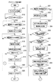
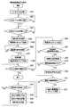
図1は実施の形態におけるプラグインハイブリッドカー及び充電に利用する電源設備の構成例を示すブロック図である。図2は図1に示すPLCユニットの構成を示すブロック図である。図3は図1に示すプラグインハイブリッドカー側に設けたPLCユニットの制御の内容を示すフローチャートである。図4は図1に示す電源設備側に設けた電源側充電監視装置の制御の内容を示すフローチャートである。図5は図3に示したPLCユニットの制御の内容に関する変形例を示すフローチャートである。図6は図4に示した電源側充電監視装置の制御の内容に関する変形例を示すフローチャートである。 FIG. 1 is a block diagram showing a configuration example of a plug-in hybrid car and power supply equipment used for charging in the embodiment. FIG. 2 is a block diagram showing the configuration of the PLC unit shown in FIG. FIG. 3 is a flowchart showing the contents of control of the PLC unit provided on the plug-in hybrid car side shown in FIG. FIG. 4 is a flowchart showing the contents of control of the power supply side charge monitoring device provided on the power supply facility side shown in FIG. FIG. 5 is a flowchart showing a modification regarding the contents of control of the PLC unit shown in FIG. FIG. 6 is a flowchart showing a modified example regarding the contents of control of the power supply side charge monitoring apparatus shown in FIG.
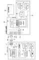
本実施の形態では、図1に示すようにプラグインハイブリッドカー(HV)10を充電用電気ケーブル15を介して電源設備20と接続し、電源設備20側からプラグインハイブリッドカー10に供給される電力を利用してバッテリ13に充電する場合を想定している。
In the present embodiment, as shown in FIG. 1, plug-in hybrid car (HV) 10 is connected to
プラグインハイブリッドカー10は、一般家庭用の電源コンセントから取り出すことのできる商用交流電力(例えばAC100V)を利用してバッテリ13の充電を行う機能を搭載している。このため、電源設備20については、必要とされる商用交流電力を供給可能な設備であれば、公共の場所に設置される設備であっても良いし、一般家庭用の設備であっても良い。電源設備20には、所定の電力供給施設30から電力が供給される。電力供給施設30は、一般的には電力会社側の設備であり、変電所や柱上変圧器等に相当する。
The plug-in
一般家庭内の電源設備の場合には、プラグインハイブリッドカー10に電力を供給するために例えば課金装置のような特別な設備は備えていないので、図1に示す電源設備20のように、電源コンセント21aに充電用電気ケーブル15の電源プラグ15aを接続すれば、プラグインハイブリッドカー10側は電源設備20からいつでも電力の供給を受けることができる。従って、プラグインハイブリッドカー10の所有者等は電源設備20の所有者の使用許可を受けることなく、あるいは電気料金を支払うことなく充電動作を行うことが可能であり、プラグインハイブリッドカー10の所有者等によって不正な充電(盗電)行為が行われる可能性もある。
In the case of a power supply facility in a general home, there is no special facility such as a billing device for supplying power to the plug-in
そこで、電源設備20側における盗電等の不正行為の対策として、電源側充電監視装置22が設けてある。また、この電源側充電監視装置22はプラグインハイブリッドカー10側で蓄積された各種情報を取得して管理したり、プラグインハイブリッドカー10に対して必要とする情報を提供するための機能も搭載している。
Therefore, a power supply side
電源側充電監視装置22は、図1に示すようにPLC(電力線通信:Power Line Communications)モデム25、パーソナルコンピュータ26、充電履歴保持部27、タコグラフDB(データベース:以下同様)41及びナビゲーションDB42を備えており、PLCモデム25の電源コードに設けられた電源プラグ28は1つの電源コンセント21c(又は21a,21b)と接続される。
As shown in FIG. 1, the power supply side
タコグラフDB41は、プラグインハイブリッドカー10などの各車両上に搭載されたデジタルタコグラフが蓄積した情報(車速、エンジン回転数など)を車両側から取得してパーソナルコンピュータ26上で管理するための記憶領域である。また、ナビゲーションDB42は、プラグインハイブリッドカー10などの各車両上に搭載されたカーナビゲーション装置が必要とする情報(例えば最新の地図情報)を車両側に提供したり、前記カーナビゲーション装置上で生成された情報を車両側から取得してパーソナルコンピュータ26上で管理するための記憶領域である。ナビゲーションDB42が保持する情報は逐次最新の情報に更新される。
The
パーソナルコンピュータ26には、電源側充電監視装置22の機能を実現するためのプログラムが組み込んであるので、このプログラムをパーソナルコンピュータ26が実行することにより図4に示すような監視制御を行うことができる。また、パーソナルコンピュータ26上には、電源設備20を特定するための固有の識別情報(電源側ID)が予め登録されている。パーソナルコンピュータ26の制御によって、プラグインハイブリッドカー10の充電動作に関する履歴情報が生成され充電履歴保持部27に蓄積される。充電履歴保持部27に蓄積される履歴情報の具体例が図7に示されている。
Since the
なお、パーソナルコンピュータ26の代わりに予めプログラムを組み込んだシングルチップのマイクロコンピュータを利用しても良いし、その機能をPLCモデム25の内部に組み込んでも良い。
Instead of the
プラグインハイブリッドカー10側には、バッテリ13を充電するための充電回路12、PLCユニット(車両側充電監視装置)14と、デジタルタコグラフ16、タコグラフDB17、ナビゲーション装置18及びナビゲーションDB19が設けてある。
On the plug-in
PLCユニット14は車両側コンセント11の電源ラインと接続されている。後述するように、PLCユニット14には盗電等の不正な充電動作に対処するための機能や、電源設備20側との間で情報を転送するための機能が搭載されている。
The
デジタルタコグラフ16は、これを搭載したプラグインハイブリッドカー10の運行状況を表す各種情報をこの車両に搭載されたセンサ(図示せず)などから例えば定期的に取得し、取得した情報をタコグラフDB17上に時系列情報として蓄積する。タコグラフDB17は情報の読み取り及び書き込みが可能な記憶装置であり、タコグラフDB17上に蓄積される情報としては、例えば車速、エンジン回転数、走行時間、走行距離、最高速度、平均速度、速度オーバー時間などがある。
The
ナビゲーション装置18は、一般的なカーナビゲーション装置と同様に、複数のGPS(Global Positioning System)衛星からの電波を受信して自車両の現在位置を測定する機能や、現在位置を含む地図を画面上に画像として表示する機能や、現在位置から指定された目的地までの経路を探索する機能や、道路上に設置されているビーコン発信器などから送信される信号を受信して渋滞情報や事故情報などに関する交通情報を取得する機能などを搭載している。ナビゲーションDB19は情報の読み取り及び書き込みが可能な記憶装置であり、ナビゲーションDB19上にはナビゲーション装置18が使用する地図情報などが保持されている。
The
図1に示すように、デジタルタコグラフ16及びナビゲーション装置18はそれぞれPLCユニット14と接続されている。PLCユニット14は、後述する制御を実施することにより、タコグラフDB17上に蓄積された情報を電源設備20側のパーソナルコンピュータ26に向けて転送したり、ナビゲーションDB19上に蓄積された情報をパーソナルコンピュータ26に向けて転送したり、パーソナルコンピュータ26側から送出される情報を利用してナビゲーションDB19の内容を最新の情報に更新することができる。
As shown in FIG. 1, the
なお、図1に示した構成例においては、PLCユニット14、デジタルタコグラフ16、ナビゲーション装置18をそれぞれ独立した装置として構成してあるが、これらの一部分あるいは全体を1つの装置として一体に構成しても良い。
In the configuration example shown in FIG. 1, the
充電回路12の入力側の電源ラインは、充電スイッチSWを介して車両側コンセント11と接続されている。従って、充電用電気ケーブル15を介して電源設備20側の電源コンセント21aと車両側コンセント11とを電気的に接続すると、電源設備20側から供給される商用交流電力が充電スイッチSWを経由して充電回路12に印加される。充電回路12は、入力される商用交流電力から充電に必要な所定の直流電力を生成し、この直流電力をバッテリ13に供給し充電する。充電スイッチSWは、例えばリレーのように接続状態を電気的に制御可能なスイッチである。
The power supply line on the input side of the charging
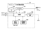
プラグインハイブリッドカー10側に搭載されているPLCユニット14には、図2に示すようにPLCモデム141、制御部142、車両ID保持部143、充電履歴保持部144、ドライバ回路145及びIDデータベース146が備わっている。
As shown in FIG. 2, the
PLCモデム141は、市販されている一般的なPLCモデムと同様に、同じ電力線に接続されている他局(他のPLCモデム)との間でこの電力線を介して情報を伝送することが可能である。この情報の伝送には周波数の高い搬送波(キャリア)を使用するので、電力の供給に影響を及ぼすことなく情報を伝送することができる。
The
車両ID保持部143は、不揮発性メモリであり、車両毎に予め定めた固有の識別情報(車両側ID)の情報を保持している。車両ID保持部143が保持しているIDは書き換えできないようになっている。
The vehicle
充電履歴保持部144は不揮発性メモリであり、充電履歴保持部144が保持する充電履歴情報の内容については、充電動作を行うときに制御部142の制御によって生成される履歴情報により逐次追加もしくは更新される。
The charging
IDデータベース146は、様々な電源設備20のそれぞれに固有に割り当てられた識別情報(電源側ID)を保持するための不揮発性メモリであり、例えば車両のユーザや特別な管理者が情報転送の安全性を確認した特定の電源設備20だけについて、それに割り当てられた電源側IDを登録し保持しておくために利用される。例えば、公共の場所に設置された電源設備20に対して車両側の情報を転送すると、転送した情報が第三者に漏れる可能性があるのでその電源側IDはIDデータベース146には登録しないが、例えば車両の所有者の自宅に設置された電源設備20や、車両を管理する特定の事業者の会社内に設置された電源設備20であれば転送した情報が漏れる可能性は小さいので、安全が確認された設備としてそれらの電源側IDをIDデータベース146に登録しておく。
The
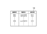
制御部142は、PLCユニット14の動作を制御するためのマイクロコンピュータであり、制御部142に接続されているPLCモデム141、車両ID保持部143、充電履歴保持部144、ドライバ回路145、IDデータベース146を用いて図3に示すような制御を実施する。この制御によって、充電動作に関する履歴情報が生成され、この履歴情報が充電履歴保持部144に蓄積される。また、制御部142の制御によって、充電を行う際にプラグインハイブリッドカー10側と電源設備20側との間で電源ライン(充電用電気ケーブル15)を経由して情報の転送が行われる。充電履歴保持部144に蓄積される履歴情報の具体例が図8に示されている。
The
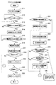
プラグインハイブリッドカー10に搭載されているPLCユニット14の動作の概要は図3に示す通りである。図3を参照しながらPLCユニット14の動作について以下に説明する。
The outline of the operation of the
ステップS11では、制御部142はPLCモデム141を起動する。
In step S <b> 11, the
ステップS12では、制御部142は充電用電気ケーブル15を介してプラグインハイブリッドカー10と電源設備20とが接続されたかどうかを調べる。つまり、充電用電気ケーブル15の電源プラグ15aが電源コンセント21aと接続され、電源プラグ15bが車両側コンセント11と接続されて充電可能な状態になったかどうかを調べる。実際には、車両側コンセント11の近傍で電源プラグ15bが挿入されたかどうかをスイッチやセンサ等で検出しても良いし、車両側コンセント11の電極に所定の電源電圧が現れているかどうかを調べても良いし、電源設備20側のPLCモデムから送出される搬送波の有無を調べても良い。
In step S12, the
ステップS13では、制御部142は、PLCモデム141が電源設備20側のPLCモデムとの間で通信可能な状態か否かを調べる。図1に示すように、電源設備20側の電源コンセント21cに電源側充電監視装置22が接続されている場合には、後述するように電源側充電監視装置22内のPLCモデム25が動作するため、プラグインハイブリッドカー10上のPLCモデム141は電源設備20側と通信可能な状態(通信路が確立された状態)になる。通信可能な状態になると次のステップS14に進む。
In step S13, the
ステップS14では、制御部142は車両ID保持部143が保持している識別情報を読み取り、このIDを車両側IDとしてPLC通信により送信する。つまり、車両側IDをPLCモデム141から電源ライン−車両側コンセント11−充電用電気ケーブル15−電源コンセント21aの電力線経路を介してPLCモデム25に送る。
In step S14, the
プラグインハイブリッドカー10上のPLCユニット14が車両側IDを送信した後で、後述するように電源設備20側に接続されている電源側充電監視装置22から電源側IDがPLC通信により送信される。そこで、次のステップS15では、制御部142はPLCユニット14が電源側IDを送信するのを待ち受ける。電源側IDを受信すると次のステップS16に進み、受信した電源側IDを充電履歴保持部144に記録する。
After the
次のステップS17では、PLCユニット14は電源側充電監視装置22に対して所定の認証要求信号を送信する。この認証要求に対して電源側充電監視装置22が認証の結果を返すので、PLCユニット14は認証の結果をステップS18で識別する。認証OKであればステップS19に進み、NGであればステップS25に進む。
In the next step S <b> 17, the
ステップS19では、制御部142はドライバ回路145を介して充電スイッチSWを制御し、充電が可能なオン状態に切り替える。つまり、電源ラインを接続するよう充電スイッチSWを駆動させて、電源設備20側から充電用電気ケーブル15を経由して車両側コンセント11に供給される電力を充電回路12に与える。従って、この時点で充電回路12はバッテリ13の充電を開始する。
In step S19, the
ステップS20では、制御部142は充電が終了したか否かを調べる。例えば、図示しない終了ボタンをユーザが操作した場合や、バッテリ13に十分な電力が蓄積されて充電回路12からバッテリ13に流れる電流が所定以下になった場合や、充電用電気ケーブル15が取り外された場合や、相手側のPLCモデムから送出される搬送波が検出されなくなった場合などを充電の終了とみなすことができる。充電中は、ステップS20〜S24及びS26〜S28の処理を繰り返し実行する。
In step S20, the
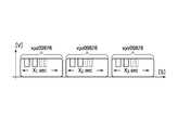
また、充電中、すなわちプラグインハイブリッドカー10と電源設備20とを接続して電源設備20からプラグインハイブリッドカー10側に電力を供給している間は、後述するように電源側充電監視装置22から電源側IDが繰り返し送信される。例えば、充電用電気ケーブル15等の電力線上には、図9に示す信号のように、電源側充電監視装置22がPLC信号として送出する電源側IDの情報が所定時間(X1秒間)に渡って繰り返し現れた後、所定時間の区切りの後、再び電源側IDの情報が所定時間(X2秒間)に渡って繰り返し現れ、更に所定時間の区切りの後、再び電源側IDの情報が所定時間(X3秒間)に渡って繰り返し現れる。なお、X1、X2、X3は同じ時間長さである。
Further, during charging, that is, while the plug-in
ステップS21では、制御部142は、PLCモデム141が電源側充電監視装置22の送出した電源側IDの受信を継続しているか、それとも前記区切りに相当する受信の中断を検出したかどうかを調べる。受信を継続している場合は次のステップS22に進み、前記区切りを検出した場合はステップS23に進む。
In step S <b> 21, the
ステップS22では、制御部142は車両ID保持部143から読み取った識別情報を車両側IDとしてPLCモデム141から再び送信する。つまり、充電中には、プラグインハイブリッドカー10側から電源設備20に対して車両側IDが繰り返し送信され、電源設備20側からプラグインハイブリッドカー10に対しては、電源側IDが繰り返し送信される。
In step S22, the
ステップS23では、制御部142は、電源側IDを受信した受信回数を計数し、その受信回数を充電履歴保持部144に記録する、具体的には、電源側IDの受信が一時的に途切れたことを表す区切りの検出回数を計数してこの区切り回数を充電履歴保持部144に記録する。例えば、PLCモデム141が図9に示すような信号を受信する場合には、X1の期間とX2の期間との間の区切りを1回目の区切りとして検出し、X2の期間とX3の期間との間の区切りを2回目の区切りとして検出し、X3の期間が終了した後で3回目の区切りを検出する。区切りを検出するたびに、履歴として充電履歴保持部144に記録する区切り検出回数が更新される。
In step S23, the
ステップS24では、制御部142はPLCモデム141が最後に検出した電源側IDを履歴として充電履歴保持部144に記録する。また、最後に検出した電源側IDと充電履歴保持部144に記録されている電源側IDとを比較して一致するかどうかを調べる。一致する場合には記録を更新する必要はないが、一致しない場合には最後に検出した電源側IDを新たな履歴として充電履歴保持部144に追加記録する。
In step S24, the
ステップS26では、制御部142はステップS21で最後に受信した電源側IDをIDデータベース146上に登録されている各IDと比較し、一致するか否かを識別する。すなわち、プラグインハイブリッドカー10の充電のために接続している電源設備20の電源側IDが予め安全性を確認したID(IDデータベース146に登録されているいずれか1つのID)であるかどうかを識別する。一致する場合はステップS27に進み、一致しない場合はステップS20に戻る。
In step S <b> 26, the
ステップS27では、制御部142はPLCモデム141が電源設備20側からの送信停止命令を受信したか否かを識別し、受信してなければステップS28に進み、受信した場合にはステップS20の処理に戻る。
In step S27, the
ステップS28では、制御部142はデジタルタコグラフ16が蓄積したタコグラフDB17上の情報を取得し、これらの情報をPLCモデム141を経由して電源設備20側に順次に送信する。
In step S <b> 28, the
充電動作が終了すると、ステップS20からステップS25に進む。ステップS25では、制御部142はドライバ回路145を介して充電スイッチSWを制御し、充電回路12の入力を車両側コンセント11等の電源ラインから切り離して充電動作を終了する。
When the charging operation ends, the process proceeds from step S20 to step S25. In step S25, the
PLCユニット14が図3に示す処理を行うことにより、充電の際には、タコグラフDB17に蓄積されている様々な情報が充電用電気ケーブル15を経由して電源設備20側のパーソナルコンピュータ26に自動的に転送される。従って、タコグラフの情報をパーソナルコンピュータ26に転送するために無線通信網やメモリカードなどを利用する必要がなく、通信コストの問題や、転送する情報に関するセキュリティの問題などを解消することができる。
When the
充電を行う際には、充電履歴保持部144上には例えば図8に示すような履歴情報が記録され保存される。図8に示す例では、それぞれの充電操作を表す履歴の情報として「履歴番号」、「電源側ID」、「接続時間」の情報が含まれている。「履歴番号」は、充電操作を行った順番を表す番号である。「電源側ID」は、PLCモデム141が電源設備20側から受信した識別情報である。「接続時間」は、ステップS23で記録される区切り検出回数である。つまり、一定時間おきに区切りが現れるので、区切り検出回数は接続時間あるいは充電動作を行っていた時間の長さに相当する。このように、「電源側ID」毎に「接続時間」が記録されることによって、これらの情報を記録する車両に各「電源側ID」からどの程度の電力が供給されたかを特定することができる。
When charging, history information as shown in FIG. 8 is recorded and stored on the charging
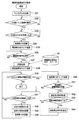
電源設備20に接続されている電源側充電監視装置22内のパーソナルコンピュータ26の動作の概要が図4に示されている。図4に示す動作について以下に説明する。
An outline of the operation of the
ステップS31では、パーソナルコンピュータ26はPLCモデム25を起動する。
In step S31, the
ステップS32では、パーソナルコンピュータ26はPLCモデム25がプラグインハイブリッドカー10側のPLCモデム141との間で通信可能かどうかを調べる。充電用電気ケーブル15を介してプラグインハイブリッドカー10が電源設備20に接続され、プラグインハイブリッドカー10上のPLCユニット14が動作しているときには、PLCモデム25がPLCユニット14内のPLCモデム141と通信可能な状態になるので、その場合には次のステップS33に進む。
In step S32, the
ステップS33では、パーソナルコンピュータ26はPLCモデム25がプラグインハイブリッドカー10側から送出される車両側IDを受信したかどうかを調べる。車両側IDを受信すると次のステップS34に進む。
In step S33, the
ステップS34では、パーソナルコンピュータ26はステップS33で受信した車両側IDを充電履歴保持部27上に記録する。
In step S34, the
ステップS35では、パーソナルコンピュータ26はその内部に予め登録されている電源側IDを読み込み、この電源側IDをPLCモデム25を介してPLC通信により送信しプラグインハイブリッドカー10側に送る。これにより、プラグインハイブリッドカー10側のPLCユニット14では、電源側IDを認識することができる。
In step S35, the
ステップS36では、パーソナルコンピュータ26はPLCモデム25がプラグインハイブリッドカー10側からの認証要求信号を受信したか否かを識別し、受信した場合にはステップS37に進む。
In step S36, the
ステップS37では、パーソナルコンピュータ26はステップS33で受信した車両側IDをIDデータベース29に登録されている各IDと比較し一致するIDが存在するか否かを識別する。IDデータベース29上には、電力供給施設30を利用可能な各車両に割り当てられた車両側IDの情報が登録され保持されている。例えば、電源設備20が有料の公共施設であるような場合には、電源設備20側で料金の支払いを確認したときに、該当する車両の車両側IDをIDデータベース29に登録するような制御を実施することも考えられる。
In step S37, the
ステップS38では、パーソナルコンピュータ26はステップS37における認証の結果をPLCモデム25を介してプラグインハイブリッドカー10側に送信する。
In step S38, the
ステップS39では、パーソナルコンピュータ26は電源設備20とプラグインハイブリッドカー10との接続状態が継続中か否かを識別する。具体的には、充電用電気ケーブル15の電源プラグ15aが電源コンセント21aに接続されているかどうかを電源コンセント21a近傍のスイッチ等(図示せず)により検出したり、プラグインハイブリッドカー10側のPLCモデム141が充電用電気ケーブル15上に送出する搬送波の有無を調べる。
In step S39, the
ステップS40では、パーソナルコンピュータ26は前記電源側IDを再びPLCモデム25を介してPLC通信により送信しプラグインハイブリッドカー10側に送る。ステップS40は繰り返し実行されるので、プラグインハイブリッドカー10が電源設備20と接続されている間は、電源側IDがPLCモデム25から短い周期で繰り返し送信される。また、前述のようにプラグインハイブリッドカー10側のPLCモデム141も車両側IDを繰り返し送信するので、パーソナルコンピュータ26はPLCモデム25が受信した車両側IDを逐次取り込んでIDデータベース29に登録済みのIDと一致するかどうかを調べる。
In step S40, the
ステップS51では、パーソナルコンピュータ26はプラグインハイブリッドカー10側が送出する蓄積情報(この例ではタコグラフの蓄積情報)をPLCモデム25が受信したかどうかを調べ、受信した場合はステップS52に進み、受信してなければステップS41に進む。
In step S51, the
ステップS52では、パーソナルコンピュータ26はPLCモデム25を制御して蓄積情報の受信処理を実行し、受信した蓄積情報を順次にタコグラフDB41上に保存する。
In step S52, the
ステップS53では、パーソナルコンピュータ26は全ての蓄積情報の受信が完了したか否かを識別し、受信を完了した場合はステップS54に進み、完了してなければステップS41に進む。
In step S53, the
ステップS54では、蓄積情報の受信が完了したことをプラグインハイブリッドカー10側に知らせるために、パーソナルコンピュータ26は所定の送信停止命令をPLCモデム25を用いて送信する。
In step S54, the
ステップS41では、パーソナルコンピュータ26は予め定めた一定時間(X秒)が経過したかどうかを調べ、経過してなければステップS39に進み、経過した時にはステップS42に進む。つまり、一定時間(X秒)毎にステップS42以降の処理が実行される。
In step S41, the
ステップS42では、パーソナルコンピュータ26は電源側IDの送信を一時的に中断するための区切り期間を生成する。具体的には、所定時間の時間待ちを行うことにより、この間だけステップS40の実行を停止し、電源側IDの送信を止める。
In step S42, the
従って、PLCモデム25がPLC通信により充電用電気ケーブル15側に送出する信号は、例えば図9に示すような状態になる。つまり、PLCモデム25がPLC信号として送出する電源側IDの情報が所定時間(X1秒間)に渡って繰り返し現れた後、所定時間の区切りの後、再び電源側IDの情報が所定時間(X2秒間)に渡って繰り返し現れ、更に所定時間の区切りの後、再び電源側IDの情報が所定時間(X3秒間)に渡って繰り返し現れる。なお、X1、X2、X3は同じ長さ(X秒)である。
Therefore, the signal sent from the
また、前述のように、電源設備20側が電源側IDの情報を送信しているときには、プラグインハイブリッドカー10側のPLCユニット14も車両側IDの送信を繰り返すので、PLCユニット14が送出する信号についても図9と同様になる。つまり、PLCモデム141がPLC信号として送出する車両側IDの情報が所定時間(X1秒間)に渡って繰り返し現れた後、所定時間の区切りの後、再び車両側IDの情報が所定時間(X2秒間)に渡って繰り返し現れ、更に所定時間の区切りの後、再び車両側IDの情報が所定時間(X3秒間)に渡って繰り返し現れる。
Further, as described above, when the
ステップS43では、パーソナルコンピュータ26は車両側IDを受信した受信回数を計数し、その受信回数を充電履歴保持部27に記録する、具体的には、ステップS42の区切りの回数を計数すると共に、この区切り回数を履歴として充電履歴保持部27に記録する。また、最後に受信した車両側IDがそれ以前に受信した車両側IDと異なる場合には、区切り回数をクリアして0から再び計数を開始する。
In step S43, the
ステップS44では、パーソナルコンピュータ26はPLCモデム25が最後に受信した車両側IDを履歴として充電履歴保持部27に記録する。また、最後に検出した車両側IDと充電履歴保持部27に記録されている車両側IDとを比較して一致するかどうかを調べる。一致する場合には記録を更新する必要はないが、一致しない場合には最後に検出した車両側IDを新たな履歴として充電履歴保持部27に追加記録する。
In step S44, the
電源側充電監視装置22が図4に示す処理を行うことにより、プラグインハイブリッドカー10が電源設備20と接続して充電を行う際に、プラグインハイブリッドカー10のデジタルタコグラフ16によって蓄積された情報を電源ラインを利用して電源側充電監視装置22側に自動的に転送し、転送した情報をタコグラフDB41に保存することができる。従って、タコグラフの情報をパーソナルコンピュータ26に転送するために無線通信網やメモリカードなどを利用する必要がなく、通信コストの問題や、転送する情報に関するセキュリティの問題などを解消することができる。
The information stored in the
充電を行う際に、充電履歴保持部27上には例えば図7に示すような履歴情報が記録され保存される。図7に示す例では、それぞれの充電操作(電力供給動作)を表す履歴の情報として「履歴番号」、「車両側ID」、「接続時間」の情報が含まれている。「履歴番号」は、充電操作を行った順番を表す番号である。「車両側ID」は、PLCモデム25がプラグインハイブリッドカー10側から受信した識別情報である。「接続時間」は、ステップS43で記録される区切り検出回数である。つまり、一定時間(X秒)おきに区切りが現れるので、区切り検出回数は接続時間あるいは充電動作を行っていた時間の長さに相当する。このように、「車両側ID」毎に「接続時間」が記録されることによって、各車両毎にどの程度の電力を供給したかを特定することができる。
When charging is performed, history information as shown in FIG. 7 is recorded and stored on the charging
なお、プラグインハイブリッドカー10側のPLCユニット14がPLC信号として送信する車両側IDの送信タイミングや、電源設備20側の電源側充電監視装置22がPLC信号として送信する電源側IDの送信タイミングなどについては、必要に応じて変更することが可能である。しかし、接続状態や充電状態が維持されているかどうかを確認可能にするために、比較的短い周期で定期的に車両側ID及び電源側IDの送信を繰り返すのが望ましい。
In addition, the transmission timing of vehicle side ID which the
上述のように、図3に示す動作をPLCユニット14が実行し、図4に示す動作を電源側充電監視装置22が実行することにより、充電の動作を制御すると共に、プラグインハイブリッドカー10側に蓄積されたタコグラフの情報を電源側充電監視装置22側に自動的に転送することができる。
As described above, the operation shown in FIG. 3 is executed by the
図3に示す動作の変形例が図5に示されており、図4に示す動作の変形例が図6に示されている。図5に示す動作をPLCユニット14が実行し、図6に示す動作を電源側充電監視装置22が実行することにより、充電の動作を制御すると共に、車両側のナビゲーションDB19が保持している情報を電源側充電監視装置22側に転送したり、逆に電源側充電監視装置22側が保持している情報を車両側に転送することができる。
A modification of the operation shown in FIG. 3 is shown in FIG. 5, and a modification of the operation shown in FIG. 4 is shown in FIG. The
なお、図5及び図6において、図3、図4と対応するステップは同一の番号を付けて示してある。すなわち、図5においては図3中のステップS28が、ステップS61〜S64に変更されている。また、図6においては図4中のステップS54とステップS41との間に、ステップS71、S72が追加されている。変更された箇所の動作について以下に説明する。 5 and 6, the steps corresponding to those in FIGS. 3 and 4 are denoted by the same reference numerals. That is, in FIG. 5, step S28 in FIG. 3 is changed to steps S61 to S64. In FIG. 6, steps S71 and S72 are added between step S54 and step S41 in FIG. The operation of the changed part will be described below.
図5に示すステップS60では、プラグインハイブリッドカー10上のPLCユニット14は、ナビゲーションDB19に蓄積されている情報のうち転送対象の情報をナビゲーション装置18を経由して取得し、この情報をPLC通信により電源側充電監視装置22側に送信する。
In step S60 shown in FIG. 5, the
ステップS60でPLCユニット14が送信する情報の具体例としては、ナビゲーション装置18が道路上に設置されたビーコン発信器などから取得した交通情報(渋滞情報や事故情報など)や、危険な箇所としてユーザ(運転者)が指定した地点の座標情報や、ナビゲーションDB19上に存在する地図データのバージョン情報などが想定される。
Specific examples of information transmitted by the
ステップS61では、プラグインハイブリッドカー10上のPLCユニット14は、電源側充電監視装置22から送信された情報を電源ラインから受信したか否かを識別し、受信した場合はステップS62に進み、受信していなければステップS20に戻る。
In step S61, the
ステップS62では、PLCユニット14はPLCモデム141を制御して受信処理を実施すると共に受信した情報を所定の記憶装置上に一時的に保存する。
In step S62, the
ステップS63ではPLCユニット14は転送が必要な全ての情報の受信が完了したか否かを識別し、受信が完了した場合はステップS64に進み、完了していなければステップS20に戻る。
In step S63, the
ステップS64では、PLCユニット14はステップS62で受信した情報を用いて、ナビゲーションDB19上の情報を最新の情報に更新する。
In step S64, the
例えば、ナビゲーション装置18が利用可能な地図などのデータベースについては、例えば定期的に最新の情報を入手することが可能であり、このような情報は例えばDVDなどの情報記録媒体として提供されたり、あるいはオンラインで接続可能なインターネット上のサーバから提供されるのが一般的である。しかし、DVDの情報記録媒体を用いる場合はそれを読み取るためのDVDドライブが必要になるし、車両上に搭載されたナビゲーション装置18をインターネットなどに接続してデータをダウンロードする場合には高額な通信コストがかかる可能性が高い。そこで、図1に示すシステムにおいては、地図などの最新の情報を電源側充電監視装置22側のナビゲーションDB42に登録しておき、プラグインハイブリッドカー10が充電を行う際にナビゲーションDB42上のデータを電源ラインを経由してプラグインハイブリッドカー10側に転送し、このデータを用いてナビゲーションDB19上の地図などを最新バージョンのデータに自動的に更新する。電源側充電監視装置22側からプラグインハイブリッドカー10に転送する情報については、地図データの他に事前にユーザが作成した旅行計画情報(目的地に関する情報、走行予定経路に関する情報、スケジュール等)なども考えられる。
For example, for a database such as a map that can be used by the
一方、図6に示すステップS71では、パーソナルコンピュータ26は転送対象となる最新の情報がナビゲーションDB42上に登録されているか否かを識別する。具体的には、各情報の登録された日時を比較したり、車両側の地図データとナビゲーションDB42上の地図データのバージョンを比較する。最新の情報が登録されている場合にはステップS72に進み、登録されていない場合はステップS41に進む。
On the other hand, in step S71 shown in FIG. 6, the
ステップS72では、パーソナルコンピュータ26はナビゲーションDB42から最新の情報を取得し、この情報をPLCモデム25を経由してプラグインハイブリッドカー10側に送信する。
In step S72, the
なお、図3に示した動作と図5に示した動作との両方をPLCユニット14側で実行し、図4に示した動作と図6に示した動作との両方を電源側充電監視装置22側で実行しても良い。これにより、タコグラフ機能に関する情報の転送とナビゲーション機能に関する情報の転送との双方を充電の際に行うことができる。
It should be noted that both the operation shown in FIG. 3 and the operation shown in FIG. 5 are executed on the
以上のように本発明の充電監視装置は、例えば電気自動車やハイブリッドカーのような車両に搭載されるバッテリを充電する動作を監視するために利用でき、特に充電の際に車両側と車両外部の電源側とを接続する電源ラインを伝送路として利用し車両側と車両外部の装置との間で情報の転送を実施するためにも利用できる。従って、情報の転送のために無線通信網を利用したり、脱着可能なメモリカードやDVDなどの情報記録媒体を利用する必要がなく、通信コストの削減や、転送する情報に関するセキュリティの確保などのために役立つ。 As described above, the charge monitoring device of the present invention can be used for monitoring the operation of charging a battery mounted on a vehicle such as an electric vehicle or a hybrid car, and particularly, the vehicle side and the outside of the vehicle are charged. The power supply line connecting the power supply side can be used as a transmission path to transfer information between the vehicle side and a device outside the vehicle. Therefore, there is no need to use a wireless communication network for information transfer, or to use an information recording medium such as a removable memory card or DVD, thereby reducing communication costs and ensuring security for information to be transferred. To help.
10 プラグインハイブリッドカー
11 車両側コンセント
12 充電回路
13 バッテリ
14 PLCユニット
15 充電用電気ケーブル
15a,15b 電源プラグ
16 デジタルタコグラフ
17 タコグラフDB
18 ナビゲーション装置
19 ナビゲーションDB
20 電源設備
21a,21b,21c 電源コンセント
22 電源側充電監視装置
25 PLCモデム
26 パーソナルコンピュータ
27 充電履歴保持部
28 電源プラグ
29 IDデータベース
30 電力供給施設
41 タコグラフDB
42 ナビゲーションDB
141 PLCモデム
142 制御部
143 車両ID保持部
144 充電履歴保持部
145 ドライバ回路
146 IDデータベース
SW 充電スイッチ
DESCRIPTION OF
18
DESCRIPTION OF
42 Navigation DB
141
Claims (7)
特定の車両に固有に割り当てられた車両側識別情報を保持する車両ID保持部と、
充電のための電力が現れる電源ラインと接続され、前記電源ラインを信号の伝送路として利用し、前記外部電源設備側の電源ラインに接続される車両外装置との間で情報を交換可能な電力線通信部と、
前記車両上で生成された情報を蓄積する車両側情報蓄積部と、
前記車両と前記外部電源設備とが接続され前記外部電源設備から供給される電力を利用して車両上のバッテリーを充電する際に、前記電力線通信部を経由して前記車両外装置との間で通信を行い、前記車両ID保持部が保持している車両側識別情報を前記車両外装置に送信すると共に、所定の条件を満たす場合には、前記車両側情報蓄積部が蓄積している情報を前記車両外装置に送信する通信制御部と
を設けたことを特徴とする充電監視装置。 A rechargeable battery is mounted, and the vehicle is configured to be able to be mounted or connected to a vehicle that can use the power supplied from the battery for traveling, from an external power supply facility provided separately from the vehicle. A charge monitoring device for monitoring the supply of power to a battery on the vehicle,
A vehicle ID holding unit for holding vehicle-side identification information uniquely assigned to a specific vehicle;
A power line that is connected to a power line on which power for charging appears, and that can exchange information with a device outside the vehicle that is connected to the power line on the external power facility side, using the power line as a signal transmission path A communication department;
A vehicle-side information storage unit for storing information generated on the vehicle;
When the vehicle and the external power supply facility are connected and the battery on the vehicle is charged using the power supplied from the external power supply facility, between the vehicle external device via the power line communication unit When communication is performed and the vehicle-side identification information held by the vehicle ID holding unit is transmitted to the outside-vehicle apparatus and a predetermined condition is satisfied, the information stored by the vehicle-side information storage unit is stored. A charge monitoring device comprising: a communication control unit that transmits to the device outside the vehicle.
前記車両側情報蓄積部として、少なくとも車両の速度及びエンジンの回転数の情報を蓄積するタコグラフの機能を搭載した
ことを特徴とする充電監視装置。 The charge monitoring device according to claim 1,
The charging monitoring device, wherein the vehicle-side information storage unit is equipped with a tachograph function for storing at least information on a vehicle speed and an engine speed.
前記車両側情報蓄積部として、少なくとも地図情報を保持すると共に車両の現在位置を測定し現在位置を含む地図を表示するナビゲーションの機能を搭載した
ことを特徴とする充電監視装置。 The charge monitoring device according to claim 1,
The charging monitoring device, wherein the vehicle-side information storage unit is equipped with a navigation function for holding at least map information, measuring a current position of the vehicle, and displaying a map including the current position.
前記車両と前記外部電源設備とが接続され前記外部電源設備から供給される電力を利用して車両上のバッテリーを充電する際に、前記車両外装置から送出される情報を前記電力線通信部を経由して受信し、受信した情報を用いて前記車両側情報蓄積部が保持している情報の内容を更新する情報更新制御部
を更に設けたことを特徴とする充電監視装置。 In the charge monitoring apparatus according to any one of claims 2 and 3,
When the vehicle and the external power supply facility are connected and the battery on the vehicle is charged using the power supplied from the external power supply facility, the information sent from the external device passes through the power line communication unit. A charge monitoring apparatus, further comprising: an information update control unit that updates the content of the information stored in the vehicle-side information storage unit using the received information.
前記通信制御部は、前記車両と前記外部電源設備とが接続され前記外部電源設備から供給される電力を利用して車両上のバッテリーを充電する際に、前記車両外装置から送出される情報を前記電力線通信部を経由して受信し、受信した情報の中に含まれる前記車両外装置を表す接続先識別情報を検出し、前記接続先識別情報を予め登録されている情報と比較し、一致する場合に限り前記車両側情報蓄積部が蓄積している情報を前記車両外装置に送信する
ことを特徴とする充電監視装置。 The charge monitoring device according to claim 1,
The communication control unit transmits information transmitted from the external device when the vehicle and the external power supply facility are connected and the battery on the vehicle is charged using electric power supplied from the external power supply facility. Receiving via the power line communication unit, detecting connection destination identification information representing the device outside the vehicle included in the received information, comparing the connection destination identification information with information registered in advance, and matching The charge monitoring device, characterized in that the information stored in the vehicle-side information storage unit is transmitted to the device outside the vehicle only when doing so.
特定の外部電源設備に固有に割り当てられた電源側識別情報を保持する電源ID保持部と、
前記外部電源設備の電源ラインと接続され、前記電源ラインを信号の伝送路として利用し、前記外部電源設備の電源ラインに接続される車両上の通信装置との間で情報を交換可能な電力線通信部と、
前記車両と前記外部電源設備とが接続され前記外部電源設備から供給される電力を利用して車両上のバッテリーを充電する際に、前記電力線通信部を経由して前記車両上の通信装置との間で通信を行い、前記電源ID保持部が保持している電源側識別情報を前記車両側に送信すると共に、前記車両側が送信する情報を前記電力線通信部を経由して受信し、受信した情報を保存する電源側受信制御部と
を設けたことを特徴とする充電監視装置。 A rechargeable battery is mounted, and the power supplied from the battery can be connected to a vehicle that can be used for traveling via a predetermined power line, and is provided separately from the vehicle. In order to monitor the supply of power from the external power supply equipment to the battery on the vehicle, a charge monitoring device connectable to the external power supply equipment side,
A power supply ID holding unit for holding power supply side identification information uniquely assigned to a specific external power supply facility;
Power line communication that is connected to the power supply line of the external power supply facility, can exchange information with a communication device on the vehicle that is connected to the power supply line of the external power supply facility using the power supply line as a signal transmission path And
When the vehicle and the external power supply facility are connected and the battery on the vehicle is charged using the power supplied from the external power supply facility, the communication device on the vehicle is connected to the vehicle via the power line communication unit. Information transmitted between the power source ID holding unit and the power source side identification information held by the power source ID holding unit is transmitted to the vehicle side, and information transmitted by the vehicle side is received via the power line communication unit. And a power supply side reception control unit for storing the charge monitoring device.
少なくとも地図を含む最新の情報を逐次取得し最新の情報を保持する地図情報保持部と、
前記車両と前記外部電源設備とが接続され前記外部電源設備から供給される電力を利用して車両上のバッテリーを充電する際に、前記電力線通信部を経由して前記車両上の通信装置との間で通信を行い、前記地図情報保持部が保持している最新の情報を前記電力線通信部を経由して車両側に送信する電源側送信制御部と
を更に設けたことを特徴とする充電監視装置。 In the charge monitoring device according to claim 6,
A map information holding unit for sequentially acquiring the latest information including at least a map and holding the latest information;
When the vehicle and the external power supply facility are connected and the battery on the vehicle is charged using the power supplied from the external power supply facility, the communication device on the vehicle is connected to the vehicle via the power line communication unit. And a power supply side transmission control unit for transmitting the latest information held by the map information holding unit to the vehicle side via the power line communication unit. apparatus.
Priority Applications (3)
| Application Number | Priority Date | Filing Date | Title |
|---|---|---|---|
| JP2008314815A JP5344895B2 (en) | 2008-12-10 | 2008-12-10 | Charge monitoring device |
| US12/635,126 US8463472B2 (en) | 2008-12-10 | 2009-12-10 | Charge monitoring apparatus |
| DE102009054483.6A DE102009054483B4 (en) | 2008-12-10 | 2009-12-10 | Charge monitoring device |
Applications Claiming Priority (1)
| Application Number | Priority Date | Filing Date | Title |
|---|---|---|---|
| JP2008314815A JP5344895B2 (en) | 2008-12-10 | 2008-12-10 | Charge monitoring device |
Publications (2)
| Publication Number | Publication Date |
|---|---|
| JP2010142001A true JP2010142001A (en) | 2010-06-24 |
| JP5344895B2 JP5344895B2 (en) | 2013-11-20 |
Family
ID=42194332
Family Applications (1)
| Application Number | Title | Priority Date | Filing Date |
|---|---|---|---|
| JP2008314815A Expired - Fee Related JP5344895B2 (en) | 2008-12-10 | 2008-12-10 | Charge monitoring device |
Country Status (3)
| Country | Link |
|---|---|
| US (1) | US8463472B2 (en) |
| JP (1) | JP5344895B2 (en) |
| DE (1) | DE102009054483B4 (en) |
Cited By (13)
| Publication number | Priority date | Publication date | Assignee | Title |
|---|---|---|---|---|
| JP2010146568A (en) * | 2008-12-22 | 2010-07-01 | General Electric Co <Ge> | Vehicle power measurement system and method |
| JP4803849B1 (en) * | 2010-12-02 | 2011-10-26 | 榮 高橋 | How to charge an electric vehicle |
| WO2012081253A1 (en) * | 2010-12-17 | 2012-06-21 | パナソニック株式会社 | Power supply device and power supply method |
| WO2012132405A1 (en) * | 2011-03-29 | 2012-10-04 | パナソニック株式会社 | In-vehicle charging device |
| JP2012250552A (en) * | 2011-05-31 | 2012-12-20 | Sony Corp | Battery device, control method, and electric vehicle |
| WO2013008429A1 (en) | 2011-07-14 | 2013-01-17 | パナソニック株式会社 | Charging apparatus and vehicle |
| WO2013027291A1 (en) * | 2011-08-25 | 2013-02-28 | トヨタ自動車株式会社 | Vehicle, charging system, and method for controlling vehicle |
| JP2013143817A (en) * | 2012-01-10 | 2013-07-22 | Toyota Motor Corp | Vehicle-mounted charging apparatus and charging system for vehicle |
| JP2013148392A (en) * | 2012-01-17 | 2013-08-01 | Denso Corp | Vehicle apparatus and traveling route guidance system |
| JP2016010001A (en) * | 2014-06-24 | 2016-01-18 | シャープ株式会社 | Information reporting device, information reporting method, information presentation device, information presentation system, vehicle, and program |
| DE112018008097T5 (en) | 2018-12-04 | 2021-08-26 | Mitsubishi Electric Corporation | Update control device and update control method |
| JP2021129359A (en) * | 2020-02-12 | 2021-09-02 | Necプラットフォームズ株式会社 | Power supply control device, electric mobile body, power supply system, power supply control method and power supply control program |
| JP2023007267A (en) * | 2021-06-30 | 2023-01-18 | テヨン チェビ カンパニー リミテッド | Electric vehicle charging system and method capable of providing additional service |
Families Citing this family (31)
| Publication number | Priority date | Publication date | Assignee | Title |
|---|---|---|---|---|
| JP5553106B2 (en) * | 2010-02-22 | 2014-07-16 | トヨタ自動車株式会社 | Power supply control device |
| US9365128B2 (en) | 2010-04-26 | 2016-06-14 | Proterra Inc. | Systems and methods for automatic connection and charging of an electric vehicle at a charging station |
| US8725330B2 (en) | 2010-06-02 | 2014-05-13 | Bryan Marc Failing | Increasing vehicle security |
| EP2631373A1 (en) * | 2010-10-22 | 2013-08-28 | Hitachi Construction Machinery Co., Ltd. | Electric construction machine |
| US20120146582A1 (en) * | 2010-12-08 | 2012-06-14 | Industrial Technology Research Institute | Systems and methods for charging battery systems of electric vehicles |
| US20150197154A1 (en) * | 2010-12-24 | 2015-07-16 | Martin Kelly Jones | Selection of battery remediation type and/or battery remediation station based upon available time period at location |
| US20150191095A1 (en) * | 2010-12-24 | 2015-07-09 | Martin Kelly Jones | Authentication Methods for Battery Remediation in Connection with Electric Powered Mobile Thing (EPMT) |
| EP3981640A1 (en) * | 2011-02-17 | 2022-04-13 | Pioneer Corporation | Charging control apparatus and method, charging system, correlation method, and computer program |
| US9419685B2 (en) * | 2011-04-15 | 2016-08-16 | Nec Corporation | Transmitter, receiver, non-contact power transmission control method, and computer-readable recording medium |
| US8823330B2 (en) | 2011-04-29 | 2014-09-02 | General Electric Company | Charging systems for use with electric vehicles and methods of monitoring same |
| JP5392861B2 (en) * | 2011-05-16 | 2014-01-22 | ソニー株式会社 | Power supply apparatus and method, power supply system, and program |
| US8990593B2 (en) | 2012-01-31 | 2015-03-24 | Silver Spring Networks, Inc. | Authentication and pairing of a mobile device to an external power source |
| CN103303154B (en) * | 2012-03-16 | 2016-04-13 | 伊顿公司 | There is the battery-driven car of high speed data transmission function, battery charger and data transmission method |
| JP5891949B2 (en) * | 2012-05-25 | 2016-03-23 | ソニー株式会社 | Information processing apparatus, connection device, communication device, information processing method, and program |
| US10176539B2 (en) * | 2013-02-27 | 2019-01-08 | Softbank Corp. | Power supply system |
| ITMO20130224A1 (en) * | 2013-08-01 | 2015-02-02 | Meta System Spa | CHARGER FOR ELECTRIC VEHICLES |
| JP5642318B1 (en) * | 2013-08-02 | 2014-12-17 | 株式会社小松製作所 | Work vehicle |
| CN103401286B (en) * | 2013-08-05 | 2016-04-27 | 博耳(无锡)电力成套有限公司 | Electric bicycle charging pile |
| CN103532202B (en) * | 2013-10-28 | 2015-07-15 | 国家电网公司 | Charging piles for wireless carrier dual-network complementation of public communities and application method thereof |
| KR101459968B1 (en) * | 2013-11-19 | 2014-11-10 | 현대자동차주식회사 | Charging demand verification method of a Electric Vehicle and the system thereof |
| US20160075249A1 (en) * | 2014-09-17 | 2016-03-17 | Qualcomm Incorporated | Methods and apparatus for user authentication in electric vehicle wireless charging |
| US11170446B1 (en) | 2014-10-28 | 2021-11-09 | State Farm Mutual Automobile Insurance Company | Systems and methods for communicating with an electric vehicle |
| EP3711488A1 (en) * | 2015-05-06 | 2020-09-23 | Snipr Technologies Limited | Altering microbial populations & modifying microbiota |
| JP6715324B2 (en) * | 2015-10-05 | 2020-07-01 | アモグリーンテック カンパニー リミテッド | Magnetic sheet, module including the same, and portable device including the same |
| US10182116B2 (en) * | 2016-05-10 | 2019-01-15 | Texas Instruments Incorporated | Contactless communication for battery information |
| DE102016212246A1 (en) * | 2016-07-05 | 2018-01-11 | Bayerische Motoren Werke Aktiengesellschaft | Method and system arrangement for identifying a vehicle at a charging station |
| CN107415720A (en) * | 2017-04-19 | 2017-12-01 | 长春汽车工业高等专科学校 | A kind of wireless charging system for electric automobile implementation method based on ZigBee |
| JP2019092279A (en) * | 2017-11-14 | 2019-06-13 | トヨタ自動車株式会社 | Vehicle and power facility |
| US10541725B1 (en) * | 2017-12-15 | 2020-01-21 | The Boeing Company | Method and apparatus for physical security over a power line connection |
| JP7528828B2 (en) * | 2021-03-15 | 2024-08-06 | トヨタ自動車株式会社 | Server, power management system and power management method |
| US12208701B2 (en) * | 2021-11-08 | 2025-01-28 | Honda Motor Co., Ltd. | System and method for identifying an electric vehicle through alternating current electric charging |
Citations (7)
| Publication number | Priority date | Publication date | Assignee | Title |
|---|---|---|---|---|
| JPH05227669A (en) * | 1992-02-14 | 1993-09-03 | Tatsuno Co Ltd | Battery charger for electric vehicles |
| JP2004205344A (en) * | 2002-12-25 | 2004-07-22 | Sharp Corp | Map information management device, map information management system, map information management method, map information management program, and computer-readable recording medium recording the program |
| JP2004246518A (en) * | 2003-02-13 | 2004-09-02 | Toyota Motor Corp | Wireless power receiving equipment and energy supply equipment |
| JP2007236173A (en) * | 2006-03-03 | 2007-09-13 | Toyota Motor Corp | VEHICLE, POWER TRANSFER METHOD AND ELECTRIC DEVICE |
| JP2007230520A (en) * | 2006-03-03 | 2007-09-13 | Toyota Motor Corp | Vehicles and vehicle information devices |
| JP2008061432A (en) * | 2006-08-31 | 2008-03-13 | Tokai Rika Co Ltd | Charging system |
| JP2008278740A (en) * | 2007-04-04 | 2008-11-13 | Furukawa Electric Co Ltd:The | Battery status detection system |
Family Cites Families (12)
| Publication number | Priority date | Publication date | Assignee | Title |
|---|---|---|---|---|
| JP2996559B2 (en) * | 1992-01-29 | 2000-01-11 | 本田技研工業株式会社 | Electric vehicle charging status display system |
| US5499181A (en) * | 1993-05-25 | 1996-03-12 | Intellectual Property Development Associates Of Connecticut, Inc. | Methods and apparatus for inputting information to a vehicle |
| US6067008A (en) * | 1993-05-25 | 2000-05-23 | Intellectual Property Development Associates Of Connecticut, Inc. | Methods and apparatus for inputting messages, including advertisements, to a vehicle |
| JP2950114B2 (en) | 1993-10-07 | 1999-09-20 | 松下電器産業株式会社 | Road traffic information transmission system |
| JP4469432B2 (en) | 1999-02-09 | 2010-05-26 | 株式会社ジャストシステム | INTERNET INFORMATION PROCESSING DEVICE, INTERNET INFORMATION PROCESSING METHOD, AND COMPUTER-READABLE RECORDING MEDIUM CONTAINING PROGRAM FOR CAUSING COMPUTER TO EXECUTE THE METHOD |
| JP4353197B2 (en) | 2006-03-13 | 2009-10-28 | トヨタ自動車株式会社 | Vehicles and electrical equipment |
| US20080052145A1 (en) * | 2006-08-10 | 2008-02-28 | V2 Green, Inc. | Power Aggregation System for Distributed Electric Resources |
| JP4931692B2 (en) | 2006-09-29 | 2012-05-16 | Udトラックス株式会社 | Vehicle operation management device and operation management system using the same |
| JP4711994B2 (en) * | 2007-03-30 | 2011-06-29 | アイシン・エィ・ダブリュ株式会社 | Navigation device and map data updating method thereof |
| JP5194964B2 (en) * | 2008-04-07 | 2013-05-08 | 日本電気株式会社 | Electric vehicle battery charging system |
| US8315930B2 (en) * | 2008-12-22 | 2012-11-20 | General Electric Company | Systems and methods for charging an electric vehicle using broadband over powerlines |
| US20100161517A1 (en) * | 2008-12-22 | 2010-06-24 | Nathan Bowman Littrell | Systems and methods for electricity metering for vehicular applications |
-
2008
- 2008-12-10 JP JP2008314815A patent/JP5344895B2/en not_active Expired - Fee Related
-
2009
- 2009-12-10 DE DE102009054483.6A patent/DE102009054483B4/en not_active Expired - Fee Related
- 2009-12-10 US US12/635,126 patent/US8463472B2/en active Active
Patent Citations (7)
| Publication number | Priority date | Publication date | Assignee | Title |
|---|---|---|---|---|
| JPH05227669A (en) * | 1992-02-14 | 1993-09-03 | Tatsuno Co Ltd | Battery charger for electric vehicles |
| JP2004205344A (en) * | 2002-12-25 | 2004-07-22 | Sharp Corp | Map information management device, map information management system, map information management method, map information management program, and computer-readable recording medium recording the program |
| JP2004246518A (en) * | 2003-02-13 | 2004-09-02 | Toyota Motor Corp | Wireless power receiving equipment and energy supply equipment |
| JP2007236173A (en) * | 2006-03-03 | 2007-09-13 | Toyota Motor Corp | VEHICLE, POWER TRANSFER METHOD AND ELECTRIC DEVICE |
| JP2007230520A (en) * | 2006-03-03 | 2007-09-13 | Toyota Motor Corp | Vehicles and vehicle information devices |
| JP2008061432A (en) * | 2006-08-31 | 2008-03-13 | Tokai Rika Co Ltd | Charging system |
| JP2008278740A (en) * | 2007-04-04 | 2008-11-13 | Furukawa Electric Co Ltd:The | Battery status detection system |
Cited By (25)
| Publication number | Priority date | Publication date | Assignee | Title |
|---|---|---|---|---|
| JP2010146568A (en) * | 2008-12-22 | 2010-07-01 | General Electric Co <Ge> | Vehicle power measurement system and method |
| JP4803849B1 (en) * | 2010-12-02 | 2011-10-26 | 榮 高橋 | How to charge an electric vehicle |
| CN103262386A (en) * | 2010-12-17 | 2013-08-21 | 松下电器产业株式会社 | Power supply device and power supply method |
| WO2012081253A1 (en) * | 2010-12-17 | 2012-06-21 | パナソニック株式会社 | Power supply device and power supply method |
| JP5899466B2 (en) * | 2010-12-17 | 2016-04-06 | パナソニックIpマネジメント株式会社 | Power supply apparatus and power supply method |
| US9090174B2 (en) | 2010-12-17 | 2015-07-28 | Panasonic intellectual property Management co., Ltd | Power supply device and power supply method |
| WO2012132405A1 (en) * | 2011-03-29 | 2012-10-04 | パナソニック株式会社 | In-vehicle charging device |
| US9409488B2 (en) | 2011-03-29 | 2016-08-09 | Panasonic Intellectual Property Management Co., Ltd. | In-vehicle charging apparatus that charges a storage battery installed in a vehicle from a power supply provided outside the vehicle |
| JP2012250552A (en) * | 2011-05-31 | 2012-12-20 | Sony Corp | Battery device, control method, and electric vehicle |
| JPWO2013008429A1 (en) * | 2011-07-14 | 2015-02-23 | パナソニック株式会社 | Charging device and vehicle |
| JP2017127191A (en) * | 2011-07-14 | 2017-07-20 | パナソニックIpマネジメント株式会社 | Charging apparatus and power supply method |
| CN103688439A (en) * | 2011-07-14 | 2014-03-26 | 松下电器产业株式会社 | Charging apparatus and vehicle |
| WO2013008429A1 (en) | 2011-07-14 | 2013-01-17 | パナソニック株式会社 | Charging apparatus and vehicle |
| US9296307B2 (en) | 2011-07-14 | 2016-03-29 | Panasonic Intellectual Property Management Co., Ltd. | Charging apparatus and vehicle |
| US8988042B2 (en) | 2011-08-25 | 2015-03-24 | Toyota Jidosha Kabushiki Kaisha | Vehicle, charging system and control method for vehicle |
| WO2013027291A1 (en) * | 2011-08-25 | 2013-02-28 | トヨタ自動車株式会社 | Vehicle, charging system, and method for controlling vehicle |
| JP5376057B2 (en) * | 2011-08-25 | 2013-12-25 | トヨタ自動車株式会社 | Vehicle and charging system, and vehicle control method |
| JP2013143817A (en) * | 2012-01-10 | 2013-07-22 | Toyota Motor Corp | Vehicle-mounted charging apparatus and charging system for vehicle |
| JP2013148392A (en) * | 2012-01-17 | 2013-08-01 | Denso Corp | Vehicle apparatus and traveling route guidance system |
| JP2016010001A (en) * | 2014-06-24 | 2016-01-18 | シャープ株式会社 | Information reporting device, information reporting method, information presentation device, information presentation system, vehicle, and program |
| DE112018008097T5 (en) | 2018-12-04 | 2021-08-26 | Mitsubishi Electric Corporation | Update control device and update control method |
| DE112018008097B4 (en) | 2018-12-04 | 2022-09-15 | Mitsubishi Electric Corporation | Update control device and update control method |
| US11797290B2 (en) | 2018-12-04 | 2023-10-24 | Mitsubishi Electric Corporation | Update control device and update control method |
| JP2021129359A (en) * | 2020-02-12 | 2021-09-02 | Necプラットフォームズ株式会社 | Power supply control device, electric mobile body, power supply system, power supply control method and power supply control program |
| JP2023007267A (en) * | 2021-06-30 | 2023-01-18 | テヨン チェビ カンパニー リミテッド | Electric vehicle charging system and method capable of providing additional service |
Also Published As
| Publication number | Publication date |
|---|---|
| DE102009054483A1 (en) | 2010-06-24 |
| JP5344895B2 (en) | 2013-11-20 |
| DE102009054483B4 (en) | 2016-11-10 |
| US20100145568A1 (en) | 2010-06-10 |
| US8463472B2 (en) | 2013-06-11 |
Similar Documents
| Publication | Publication Date | Title |
|---|---|---|
| JP5344895B2 (en) | Charge monitoring device | |
| JP5305504B2 (en) | Charge monitoring device | |
| EP3656604B1 (en) | Charging station monitoring system | |
| JP2012053821A (en) | Charging facility information providing device | |
| JP2010017007A (en) | Charge monitoring device | |
| WO2004031547A1 (en) | Emission amount report device, system for charge for exhaust gas from vehicle, management unit and inspection device making up the system | |
| US10026068B2 (en) | Charging fee payment system and target apparatus used in the same | |
| JP7548135B2 (en) | Vehicle, ground power supply device and non-contact power supply system | |
| JP2021056595A (en) | Information providing device and information providing system | |
| CN115534736B (en) | Abnormality detection apparatus and abnormality detection method therefor | |
| JP2023000406A (en) | Power supply management device and abnormality determination method | |
| JP2023000390A (en) | vehicle | |
| JP5165713B2 (en) | Electric vehicle power supply device | |
| EP4257408A1 (en) | Moving body, ground power feed device, and non-transitory storage medium | |
| JP7524845B2 (en) | server | |
| KR20110041626A (en) | Vehicle mounting device, removable vehicle video storage device and driving information providing method | |
| JP2017054423A (en) | Vehicle operation information recording device | |
| KR101217537B1 (en) | Electronic terminal device for car and management system using it | |
| CN113928181A (en) | Battery management support device and battery management support method | |
| JP5120831B2 (en) | In-vehicle information collection system | |
| KR101252965B1 (en) | Charging apparatus for electric vehicle and control method of electric vehicle | |
| KR20100136697A (en) | Method and system for providing electric charging and charging service using power line communication | |
| CN118900788A (en) | Ground power supply device, contactless power supply system, control method of ground power supply device, and computer program | |
| CN118451442A (en) | Non-contact power supply system, server, and utilization cost calculation method for non-contact power supply system | |
| KR20020019350A (en) | Method for data accurate of card reader using wireless type telecommunication unit |
Legal Events
| Date | Code | Title | Description |
|---|---|---|---|
| A621 | Written request for application examination |
Free format text: JAPANESE INTERMEDIATE CODE: A621 Effective date: 20111101 |
|
| A131 | Notification of reasons for refusal |
Free format text: JAPANESE INTERMEDIATE CODE: A131 Effective date: 20130122 |
|
| A521 | Request for written amendment filed |
Free format text: JAPANESE INTERMEDIATE CODE: A523 Effective date: 20130325 |
|
| TRDD | Decision of grant or rejection written | ||
| A01 | Written decision to grant a patent or to grant a registration (utility model) |
Free format text: JAPANESE INTERMEDIATE CODE: A01 Effective date: 20130716 |
|
| A61 | First payment of annual fees (during grant procedure) |
Free format text: JAPANESE INTERMEDIATE CODE: A61 Effective date: 20130813 |
|
| R150 | Certificate of patent or registration of utility model |
Ref document number: 5344895 Country of ref document: JP Free format text: JAPANESE INTERMEDIATE CODE: R150 Free format text: JAPANESE INTERMEDIATE CODE: R150 |
|
| R250 | Receipt of annual fees |
Free format text: JAPANESE INTERMEDIATE CODE: R250 |
|
| R250 | Receipt of annual fees |
Free format text: JAPANESE INTERMEDIATE CODE: R250 |
|
| R250 | Receipt of annual fees |
Free format text: JAPANESE INTERMEDIATE CODE: R250 |
|
| R250 | Receipt of annual fees |
Free format text: JAPANESE INTERMEDIATE CODE: R250 |
|
| R250 | Receipt of annual fees |
Free format text: JAPANESE INTERMEDIATE CODE: R250 |
|
| R250 | Receipt of annual fees |
Free format text: JAPANESE INTERMEDIATE CODE: R250 |
|
| R250 | Receipt of annual fees |
Free format text: JAPANESE INTERMEDIATE CODE: R250 |
|
| S531 | Written request for registration of change of domicile |
Free format text: JAPANESE INTERMEDIATE CODE: R313531 |
|
| R350 | Written notification of registration of transfer |
Free format text: JAPANESE INTERMEDIATE CODE: R350 |
|
| R250 | Receipt of annual fees |
Free format text: JAPANESE INTERMEDIATE CODE: R250 |
|
| LAPS | Cancellation because of no payment of annual fees |