JP2010141118A - Substrate type discriminating method, part mounter, and program - Google Patents
Substrate type discriminating method, part mounter, and program Download PDFInfo
- Publication number
- JP2010141118A JP2010141118A JP2008315814A JP2008315814A JP2010141118A JP 2010141118 A JP2010141118 A JP 2010141118A JP 2008315814 A JP2008315814 A JP 2008315814A JP 2008315814 A JP2008315814 A JP 2008315814A JP 2010141118 A JP2010141118 A JP 2010141118A
- Authority
- JP
- Japan
- Prior art keywords
- substrate
- type
- board
- mark
- predetermined
- Prior art date
- Legal status (The legal status is an assumption and is not a legal conclusion. Google has not performed a legal analysis and makes no representation as to the accuracy of the status listed.)
- Pending
Links
Images









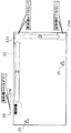
Landscapes
- Supply And Installment Of Electrical Components (AREA)
Abstract
【課題】識別精度の高い基板種識別方法を提供する。
【解決手段】部品実装機に搬入された基板の基板種を識別する基板種識別方法であって、搬入された基板の基板種が、所定の基板種であると仮決定する仮決定ステップ(S2)と、仮決定した前記所定の基板種の基板に付される基板マークの位置であって、基板種固有の位置を示す位置情報を取得する取得ステップ(S4)と、基板の搬入時に、前記位置情報で特定される位置へ、前記基板マークを認識するための基板カメラを移動させ、前記基板カメラにより当該位置を撮像する撮像ステップ(S6)と、前記撮像ステップで得られた画像に基づいて、前記位置情報で特定される位置における前記基板マークの有無を検知し、前記基板マークが有ると検知された場合には、搬入された前記基板の基板種が、仮決定した前記所定の基板種と同じであると判断する判断ステップ(S6〜S10)とを含む。
【選択図】図14A method for identifying a substrate type with high identification accuracy is provided.
A substrate type identification method for identifying a substrate type of a board carried into a component mounting machine, wherein the board type of the board carried in is temporarily determined to be a predetermined board type (S2). ), An acquisition step (S4) for acquiring position information indicating the position of the substrate mark attached to the substrate of the predetermined substrate type that is provisionally determined, and indicating the position specific to the substrate type; Based on the imaging step (S6) of moving the substrate camera for recognizing the substrate mark to the position specified by the position information and imaging the position by the substrate camera, and the image obtained in the imaging step The presence or absence of the substrate mark at the position specified by the position information is detected, and if it is detected that the substrate mark is present, the substrate type of the substrate carried in is the predetermined predetermined substrate type Same as And a determination step (S6 to S10) which determines that.
[Selection] Figure 14
Description
本発明は、部品実装機に搬入された基板の基板種を識別する基板種識別方法に関し、特に、基板マークを利用して基板の基板種を識別する基板種識別方法に関する。 The present invention relates to a board type identifying method for identifying a board type of a board carried into a component mounter, and more particularly to a board type identifying method for identifying a board type of a board using a board mark.
部品実装機において回路基板を生産するためには、部品実装機に搬入された基板の基板種が、これから部品が実装される予定の基板の基板種であるか否かを識別する必要がある。このような基板種の識別を行うことにより、誤った基板に部品が実装されるというミスを防ぐことができる。特に、基板の表面及び裏面の双方に部品を実装する場合には、いずれの面の基板が部品実装機に搬入されるか否か不明な場合がある。よって、このような状況では、基板種を識別することが重要である。なお、本明細書及び特許請求の範囲では、同一の基板であっても面が異なる場合には、基板種が異なるものと考える。 In order to produce a circuit board in a component mounting machine, it is necessary to identify whether or not the board type of the board carried into the component mounting machine is the board type of the board on which the component is to be mounted. By identifying such a board type, it is possible to prevent a mistake that a component is mounted on the wrong board. In particular, when components are mounted on both the front surface and the back surface of the board, it may be unclear whether the board on either side is carried into the component mounter. Therefore, it is important to identify the substrate type in such a situation. In the present specification and claims, it is considered that the substrate types are different if the surfaces of the same substrate are different.
従来、基板種識別方法として、基板上に設けられた基板マークの形状を認識することにより、基板種を識別する方法が提案されている(例えば、特許文献1参照。)。 Conventionally, as a substrate type identification method, a method of identifying a substrate type by recognizing the shape of a substrate mark provided on the substrate has been proposed (for example, see Patent Document 1).
また、他の識別方法として、基板上に設けられ、かつ基板種に固有のバーコードを読み取ることにより、基板種を識別する方法が提案されている(例えば、特許文献2参照。)。
しかしながら、特許文献1に記載の方法によると、基板マークの形状を誤認識した場合には、基板種の誤判定につながるという問題がある。基板マークの形状の誤認識は、例えば、画像処理時の2値化閾値が適切に設定されていない場合などに生じる。
However, according to the method described in
また、特許文献2に記載の方法によると、基板種の識別のために、基板カメラをバーコードの位置に移動させたり、バーコードを読み込んだりするための時間が必要となる。この間、基板マークの認識又は部品実装をすることができないため、基板の生産性が低下するという問題がある。
In addition, according to the method described in
本発明は、上述の課題を解決するためになされたものであり、識別精度の高い基板種識別方法を提供することを目的とする。 The present invention has been made to solve the above-described problems, and an object of the present invention is to provide a substrate type identification method with high identification accuracy.
また、基板の生産性を低下させることのない基板種識別方法を提供することも目的とする。 It is another object of the present invention to provide a substrate type identification method that does not reduce substrate productivity.
上記目的を達成するために、本発明に係る基板種識別方法は、部品実装機に搬入された基板の基板種を識別する基板種識別方法であって、搬入された基板の基板種が、所定の基板種であると仮決定する仮決定ステップと、仮決定した前記所定の基板種の基板に付される基板マークの位置であって、基板種固有の位置を示す位置情報を取得する取得ステップと、基板の搬入時に、前記位置情報で特定される位置へ、前記基板マークを認識するための基板カメラを移動させ、前記基板カメラにより当該位置を撮像する撮像ステップと、前記撮像ステップで得られた画像に基づいて、前記位置情報で特定される位置における前記基板マークの有無を検知し、前記基板マークが有ると検知された場合には、搬入された前記基板の基板種が、仮決定した前記所定の基板種と同じであると判断する判断ステップとを含む。 In order to achieve the above object, a board type identifying method according to the present invention is a board type identifying method for identifying a board type of a board carried into a component mounter, wherein the board type of the board carried in is predetermined. A provisional determination step for provisionally determining that the substrate type is a substrate type, and an acquisition step for acquiring position information indicating a position specific to the substrate type, which is a position of a substrate mark attached to the substrate of the predetermined substrate type that has been provisionally determined Obtained by the imaging step of moving the substrate camera for recognizing the substrate mark to the position specified by the position information when the substrate is loaded, and imaging the position by the substrate camera, and Based on the obtained image, the presence or absence of the substrate mark at the position specified by the position information is detected, and when it is detected that the substrate mark is present, the substrate type of the loaded substrate is provisionally determined. Serial and a determining step of determining to be the same as given board type.
この方法によると、基板種毎に基板マークの位置を異ならせ、仮決定した所定の基板種の基板マークの位置における基板マークの有無を検知する。これにより、部品実装機に搬入された基板の基板種が仮決定した所定の基板種と等しいか否かを判断している。基板マークの認識処理は、基板マークの有無のみを検知する処理であるため、基板種の形状を認識する従来の処理に比べて認識精度が高い処理である。このため、基板種の誤判定を起こしにくい。 According to this method, the position of the substrate mark is made different for each substrate type, and the presence or absence of the substrate mark at the position of the substrate mark of the predetermined predetermined substrate type is detected. Accordingly, it is determined whether or not the board type of the board carried into the component mounting machine is equal to the predetermined board type that has been provisionally determined. The substrate mark recognition process is a process that detects only the presence or absence of a substrate mark, and is therefore a process with higher recognition accuracy than the conventional process for recognizing the shape of a substrate type. For this reason, it is difficult to cause erroneous determination of the substrate type.
また、基板マークの認識処理は、部品実装に先立って必須の処理である。このため、特殊な処理を行うことなく、基板種を判別することができる。よって、基板の生産性を低下させることなく、基板種を判別することができる。 The board mark recognition process is an essential process prior to component mounting. For this reason, it is possible to discriminate the substrate type without performing a special process. Therefore, the substrate type can be discriminated without reducing the productivity of the substrate.
好ましくは、前記仮決定ステップにおいて、さらに、前記判断ステップにおいて前記基板マークが無いと検知された場合には、前記搬入された基板の基板種が、仮決定した前記所定の基板種とは異なる他の基板種であると仮決定しなおし、前記仮決定ステップにおいて前記他の基板種に仮決定しなおされた場合には、前記取得ステップ、前記撮像ステップ及び前記判断ステップを再度実行する。 Preferably, in the provisional determination step, when it is detected in the determination step that the substrate mark is not present, the substrate type of the carried-in substrate is different from the predetermined substrate type that has been provisionally determined. If the substrate type is tentatively determined again and the other substrate type is tentatively determined in the tentative determination step, the acquisition step, the imaging step, and the determination step are executed again.
さらに好ましくは、前記仮決定ステップにおいて、予め定められた基板種の優先順位に従って、前記搬入された基板の基板種を仮決定する。 More preferably, in the provisional determination step, the substrate type of the loaded substrate is provisionally determined in accordance with a predetermined priority order of the substrate types.
さらに好ましくは、前記予め定められた基板種の優先順位は、生産枚数の計画値が多い基板種ほど高くなる優先順位である。 More preferably, the predetermined priority order of the board types is a higher priority order as the board type has a larger planned number of produced sheets.
搬入された基板の基板種を、生産枚数の計画値が多い基板種に優先的に仮決定するように、優先順序が決められている。このため、生産枚数が多い基板ほど、早期に基板マークが有ると検知され、早期に基板種が決定される。よって、基板の生産性の低下を極力抑えることができる。 The priority order is determined so that the substrate types of the loaded substrates are provisionally determined preferentially to the substrate types having a large planned number of produced sheets. For this reason, it is detected that there is a board mark earlier as the number of produced boards increases, and the board type is determined earlier. Therefore, it is possible to suppress a decrease in the productivity of the substrate as much as possible.
また、前記予め定められた基板種の優先順位は、基板1枚あたりの部品実装時間が長い基板種ほど高くなる優先順位であってもよい。 Further, the predetermined priority order of the board types may be a priority order that becomes higher as the board type has a longer component mounting time per board.
搬入された基板の基板種を、基板1枚あたりの部品実装時間が長い基板種に優先的に仮決定するように、優先順序が決められている。このため、部品が実装された実装基板を生産するのに要する合計時間のばらつきを基板種間で少なくすることができる。 The priority order is determined so that the board type of the board that has been loaded is provisionally determined preferentially to the board type having a long component mounting time per board. For this reason, the dispersion | variation in the total time required to produce the mounting board | substrate with which components were mounted can be reduced between board | substrate types.
また、前記仮決定ステップにおける初回の仮決定では、基板の搬入時に、前記基板カメラが、前記基板に付され、かつ基板種に固有のマークである判別マークを認識し、認識結果に基づいて、前記搬入された基板の基板種を仮決定してもよい。 Further, in the initial provisional decision in the provisional decision step, the substrate camera recognizes a discrimination mark that is attached to the substrate and unique to the substrate type when the substrate is loaded, and based on the recognition result, The substrate type of the loaded substrate may be provisionally determined.
判別マークの認識を行い、その結果に基づいて、基板種を仮決定することにより、搬入が想定されているいずれの基板種の基板が搬入されたとしても、早期に基板マークが有ると検知され、早期に基板種が決定される。このため、基板の生産性の低下を極力抑えることができる。 By recognizing the discrimination mark and tentatively determining the substrate type based on the result, it is detected that there is a substrate mark at an early stage, regardless of the substrate type that is expected to be loaded. The substrate type is determined early. For this reason, the fall of the productivity of a board | substrate can be suppressed as much as possible.
なお、本発明は、このような特徴的なステップを含む基板種識別方法として実現することができるだけでなく、基板種識別方法に含まれる特徴的なステップを処理部として備える部品実装機として実現することができる。また、基板種識別方法に含まれる特徴的なステップをコンピュータに実行させるプログラムとして実現することもできる。そして、そのようなプログラムは、CD−ROM(Compact Disc-Read Only Memory)等の記録媒体やインターネット等の通信ネットワークを介して流通させることができるのは言うまでもない。 The present invention can be realized not only as a board type identification method including such characteristic steps, but also as a component mounter including the characteristic steps included in the board type identification method as a processing unit. be able to. It can also be realized as a program that causes a computer to execute characteristic steps included in the substrate type identification method. Needless to say, such a program can be distributed via a recording medium such as a CD-ROM (Compact Disc-Read Only Memory) or a communication network such as the Internet.
本発明によると、識別精度の高い基板種識別方法を提供することができる。また、基板の生産性を低下させない基板種識別方法も提供することができる。 According to the present invention, it is possible to provide a substrate type identification method with high identification accuracy. In addition, it is possible to provide a substrate type identification method that does not reduce the productivity of the substrate.
以下、本発明の実施の形態に係る部品実装機について説明する。 Hereinafter, a component mounter according to an embodiment of the present invention will be described.
(実施の形態1)
実施の形態1では、基板マークの認識時に、基板の基板種を識別する方法について説明する。
(Embodiment 1)
In the first embodiment, a method for identifying a substrate type of a substrate when a substrate mark is recognized will be described.
図1は、本発明の実施の形態1に係る部品実装機の外観図である。
部品実装機120は、生産ラインの上流から下流に向けて基板を送りながら電子部品を実装していく装置である。
FIG. 1 is an external view of a component mounter according to
The
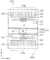
図2は、部品実装機120内部の主要な構成を示す平面図である。
部品実装機120は、その内部に基板20の搬送方向(X軸方向)と直交する部品実装機120の前後方向(Y軸方向)に前サブ設備120a及び後サブ設備120bを備えている。なお、本実施の形態及び以降の実施の形態では、前サブ設備120a、後サブ設備120bとあるように、装着ヘッド121が前側と後側とに備えられている部品実装機120の事例について説明するが、本発明が適用される部品実装機はそのようなものに限定されない。例えば、基板20の搬送方向に上流側の装着ヘッド121と下流側の装着ヘッド121とが備わり、基板20に対して交互に部品を実装する部品実装機であってもよい。また、装着ヘッド121が1つのみ又は3つ以上備えられている部品実装機であってもよい。
FIG. 2 is a plan view showing a main configuration inside the
The
前サブ設備120a及び後サブ設備120bは、お互いが協調し1枚の基板20に対して実装作業を行う。
The
前サブ設備120a及び後サブ設備120bは、部品供給部125a及び部品供給部125bをそれぞれ備えている。また、前サブ設備120a及び後サブ設備120bの各々は、ビーム122と、装着ヘッド121と、ノズルチェンジャ127とを備えている。さらに、部品実装機120には前後のサブ設備間に基板20搬送用のレール129が一対備えられている。
The
部品供給部125a及び部品供給部125bの各々は、部品テープを収納する部品カセット123の配列である。
Each of the
ここで、「部品テープ」とは、同一部品種の複数の部品がテープ(キャリアテープ)上に並べられたものであり、リール(供給リール)等に巻かれた状態で供給される。主に、チップ部品と呼ばれる比較的小さいサイズの部品を部品実装機に供給するのに使用される。 Here, the “component tape” is a plurality of components of the same component type arranged on a tape (carrier tape), and is supplied in a state of being wound around a reel (supply reel) or the like. It is mainly used to supply a relatively small size component called a chip component to a component mounter.
ノズルチェンジャ127は、交換用の複数の吸着ノズルを保持する。この交換用の吸着ノズルとは、装着ヘッド121が備えている吸着ノズルでは吸着できない部品があったり、吸着ノズルに異常があったりした場合などに、交換するための吸着ノズルである。
The
レール129は、固定レール129aと可動レール129bとからなり、固定レール129aの位置は予め固定されているものの、可動レール129bは、搬送される基板20のY軸方向の長さに応じてY軸方向に移動可能な構成になっている。
The
なお、装着ヘッド121により吸着された部品を認識するための部品認識カメラ及びトレイ上に載置された部品を供給するためのトレイ供給部などは本願発明の主眼ではないため、同図においてその記載を省略している。
Note that the component recognition camera for recognizing the component sucked by the mounting
ビーム122は、X軸方向(基板20の搬送方向)に延びた剛体であって、Y軸方向(基板20の搬送方向と垂直方向)に設けられた軌道(図示せず)上をX軸方向と平行を保ったままで移動することができるものである。また、ビーム122は、当該ビーム122に取り付けられた装着ヘッド121をビーム122に沿って、すなわちX軸方向に移動させることができるものであり、自己のY軸方向の移動と、これに伴ってY軸方向に移動する装着ヘッド121のX軸方向の移動とで装着ヘッド121をXY平面内で自在に移動させることができる。また、これらを駆動させるためのモータ(図示せず)など複数のモータがビーム122に備えられており、ビーム122を介してこれらモータなどに電力が供給されている。
The
図3及び図4は、部品実装機120による部品実装について説明するための図である。
図3に示されるように、後サブ設備120bの装着ヘッド121は、部品供給部125bからの部品の「吸着」、吸着した部品の部品認識カメラ126による「認識」及び認識された部品の基板20への「装着」という3つの動作を交互に繰り返すことにより、部品を基板20上に実装していく。
3 and 4 are diagrams for explaining component mounting by the
As illustrated in FIG. 3, the mounting
なお、前サブ設備120aの装着ヘッド121も同様に、「吸着」、「認識」及び「装着」という3つの動作を交互に繰り返すことにより、部品を基板20上に実装していく。
Similarly, the mounting
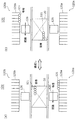
なお、2つの装着ヘッド121が同時に部品の「装着」を行う場合において、装着ヘッド121同士の衝突を防ぐために、2つの装着ヘッド121は、協調動作を行ないながら部品を基板20上に実装していく。具体的には、図4(a)に示されるように、後サブ設備120bの装着ヘッド121が「装着」動作を行なっている際には、前サブ設備120aの装着ヘッド121は「吸着」動作及び「認識」動作を行なう。逆に、図4(b)に示されるように、前サブ設備120aの装着ヘッド121が「装着」動作を行なっている際には、後サブ設備120bの装着ヘッド121は「吸着」動作及び「認識」動作を行なう。このように、「装着」動作を2つの装着ヘッド121が交互に行なうことにより、装着ヘッド121同士の衝突を防ぐことができる。なお、理想的には、一方の装着ヘッド121による「装着」動作を行なっている間に、他方の装着ヘッド121による「吸着」動作及び「認識」動作が終了していれば、一方の装着ヘッド121による「装着」動作が完了した時点で、滞りなく他方の装着ヘッド121による「装着」動作に移ることができ、生産効率を向上させることができる。
When the two mounting
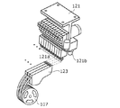
図5は、装着ヘッド121及び部品カセット123の外観を示す斜視図である。
部品カセット123は、多数の部品を保持する部品テープが巻き付けられる部品リール107が取り付けられ、部品テープに保持される部品を順次装着ヘッド121による吸着位置に供給する装置である。
FIG. 5 is a perspective view showing the external appearance of the mounting
The
装着ヘッド121は、その先端に複数の吸着ノズル121aを備える。各吸着ノズル121aは、部品供給部125aから供給される部品を真空吸引により吸着する。1本の吸着ノズル121aにつき1つの部品を保持することが可能であり、装着ヘッド121は、吸着ノズル121aの本数に応じた数量の部品を1度に保持することが可能となる。同図に示される装着ヘッド121は吸着ノズル121aを10本備えているため、最大10個の部品を一度に保持することができる。吸着ノズル121aには、形状又は大きさの異なる複数種類の吸着ノズル121aが存在する。このため、吸着する部品の大きさ、重量又は形状に応じて、吸着ノズル121aを変更することにより、さまざまな大きさや形状の部品を装着ヘッド121で保持することができる。
The mounting
また、装着ヘッド121は、基板カメラ121bを備える。基板カメラ121bは、基板20上に設けられた基板20の位置決め用の基板マークを認識するためのカメラである。装着ヘッド121を基板マークの位置に移動させた後、基板カメラ121bで基板マークの位置を撮像することにより、基板マークの有無が検知される。
The mounting
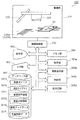
図6は、部品実装機120の機能的な構成を示すブロック図である。
部品実装機120は、機構部131と、機構制御部132と、表示部302、入力部303、メモリ部304、取得部305a、撮像指示部305b、判断部305c、仮決定部305d及びデータベース部307等から構成される。
FIG. 6 is a block diagram showing a functional configuration of the
The
機構部131は、装着ヘッド121、ビーム122、部品供給部125a(125b)等を含む機構関連の構成要素の集合である。
The
機構制御部132は、機構部131を制御する処理部である。
表示部302はCRT(Cathode-Ray Tube)やLCD(Liquid Crystal Display)等であり、入力部303はキーボードやマウス等であり、これらは、部品実装機120とオペレータとが対話する等のために用いられる。
The
The
仮決定部305dは、搬入された基板の基板種が、所定の基板種であると仮決定する処理部である。 The provisional determination unit 305d is a processing unit that provisionally determines that the substrate type of the loaded substrate is a predetermined substrate type.
取得部305aは、仮決定した所定の基板種の基板に付される基板マークの位置であって、基板種固有の位置を示す位置情報を取得する処理部である。 The acquisition unit 305a is a processing unit that acquires position information indicating a position of a substrate mark attached to a substrate of a predetermined predetermined substrate type and indicating a position unique to the substrate type.
撮像指示部305bは、基板の搬入時に、前記位置情報で特定される位置へ基板カメラ121bを移動させ、基板カメラ121bにより当該位置を撮像させる処理部である。
The
判断部305cは、基板カメラ121bにより得られた画像に基づいて、前記位置情報で特定される位置における基板マークの有無を検知し、基板マークが有ると検知された場合には、搬入された基板の基板種は、仮決定した所定の基板種と同じであると判断する処理部である。
Based on the image obtained by the
メモリ部304は、取得部305a、撮像指示部305b、判断部305c及び機構制御部132による処理実行時の作業領域を提供するRAM(Random Access Memory)等である。
The
データベース部307は、この部品実装機120による実装条件決定処理等に用いられる入力データ(実装点データ307a、部品ライブラリ307b、実装装置情報307c、実装点数情報307d等)や、部品実装機120による基板種識別処理等に用いられる入力データ(基板マークデータ307e、生産枚数データ307f等)を記憶するハードディスク等である。
The
機構制御部132、取得部305a、撮像指示部305b及び判断部305cは、本発明に係るプログラムを、CPU上で実行することにより実現される。
The
図7〜図10は、それぞれ、実装点データ307a、部品ライブラリ307b、実装装置情報307c及び実装点数情報307dの一例を示す図である。
7 to 10 are diagrams illustrating examples of the mounting
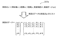
実装点データ307aは、実装の対象となる全ての部品の実装点を示す情報の集まりである。図7に示されるように、1つの実装点piは、部品種ci、X座標xi、Y座標yi、実装角度θi、制御データφiからなる。ここで、「部品種」は、図8に示される部品ライブラリ307bにおける部品名に相当し、「X座標」及び「Y座標」は、実装点の座標(基板上の特定位置を示す座標)であり、「実装角度」は、部品を基板に実装する際の部品の回転角度であり、「制御データ」は、その部品の実装に関する制約情報(使用可能な吸着ノズルのタイプ、装着ヘッド121の最高移動速度等)である。なお、最終的に求めるべきNC(Numeric Control)データは、ラインタクトが最小となるような実装点の並びである。
The mounting
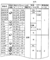
部品ライブラリ307bは、部品実装機120等が扱うことができる全ての部品種それぞれについての固有の情報を集めたライブラリであり、図8に示されるように、部品種ごとの部品サイズ、タクト(一定条件下における部品種に固有のタクト)、その他の制約情報(使用可能な吸着ノズルのタイプ、部品認識カメラ126による認識方式、装着ヘッド121の最高速度レベル等)からなる。なお、本図には、参考として、各部品種の部品の外観も併せて示されている。
The
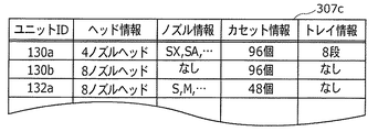
実装装置情報307cは、部品実装機120を構成するサブ設備ごとの装置構成や上述の制約等を示す情報であり、図9に示されるように、装着ヘッド121のタイプ、すなわち装着ヘッド121に備えられている吸着ノズルの本数等に関するヘッド情報、装着ヘッド121に装着され得る吸着ノズルのタイプ等に関するノズル情報、部品カセット123の最大数等に関するカセット情報、トレイ供給部が収納しているトレイの段数等に関するトレイ情報等からなる。
The mounting
実装点数情報307dは、基板20上に実装される実装点の部品種と、その員数(実装点数)とが対応付けられている情報である。図10に示されるように、部品実装機120で実装される部品種は、A、B、C、D及びEの5種類であり、それぞれの実装点数は、6、7、8、9及び2であることが示されている。
The mounting
図11は、基板マークデータ307eの一例を示す図である。
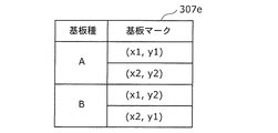
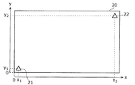
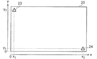
基板マークデータ307eは、部品の実装対象となる基板の基板種毎の基板マークの位置を示す情報であり、図11に示されるように、基板種名や基板マークの位置等からなる情報である。例えば、図11に示される基板マークデータ307eには、図12Aに示すように、基板種Aの基板20の座標(x1,y1)及び(x2,y2)の位置に基板マークが設けられていることが示されている。また、図12Bに示すように、基板種Bの基板20の座標(x1,y2)及び(x2,y1)の位置に基板マークが設けられていることが示されている。なお、本実施の形態では、部品実装の対象とされる基板の基板種として基板種A及びBの2種類を想定しているが、基板種数は1種類であってもよいし、3種類以上であっても良い。
FIG. 11 is a diagram illustrating an example of the
The
図13は、生産枚数データ307fの一例を示す図である。
生産枚数データ307fは、図13に示されるように、基板種ごとの生産枚数の計画値を示す情報である。例えば、図13に示される生産枚数データ307fには、基板種Aの基板20の生産枚数の計画値が300枚であり、基板種Bの基板20の生産枚数の計画値が150枚であることが示されている。
FIG. 13 is a diagram illustrating an example of the
As shown in FIG. 13, the
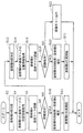
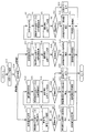
図14は、部品実装機120による部品実装処理を説明するためのフローチャートである。
FIG. 14 is a flowchart for explaining component mounting processing by the
仮決定部305dは、部品実装機120に搬入されてくる基板の基板種が、基板種Aであると仮決定する(S2)。例えば、仮決定部305dは、生産枚数データ307fを参照し、部品実装機120に搬入されてくる基板の基板種が、最も生産枚数の計画値が大きい基板種であると仮決定する。なお、仮決定した基板種の情報は、メモリ部304に書込まれる。
The provisional determination unit 305d provisionally determines that the board type of the board carried into the
取得部305aは、仮決定部305dにより仮決定した基板種Aの基板マークの位置情報を基板マークデータ307eより取得し、メモリ部304に記憶する(S4)。つまり、図11に示す基板マークデータ307eより、基板種Aの基板マークの位置情報として、座標(x1,y1)及び(x2,y2)を取得する。
The acquisition unit 305a acquires the substrate mark position information of the substrate type A temporarily determined by the temporary determination unit 305d from the
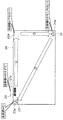
撮像指示部305b及び判断部305cは、部品実装機120の定位置に基板20が搬入されてくると、基板20上に存在すべき基板種Aの基板マークを認識する(S6)。つまり、図15Aに示すように、撮像指示部305bは、座標(x2,y2)で特定される基板マーク22の位置を撮像しうる位置へ基板カメラ121bを移動させ、基板カメラ121bによりその位置周辺の領域22aを撮像する。判断部305cは、領域22aの画像中における基板マーク22の有無を検知する。基板マーク22が有ると検知された場合には、撮像指示部305bは、さらに、基板カメラ121bを操作し、座標(x1,y1)で特定される基板マーク21の位置を撮像しうる位置へ基板カメラ121bを移動させ、基板カメラ121bによりその位置周辺の領域21aを撮像する。判断部305cは、領域21aの画像中における基板マーク21の有無を検知する。
The
判断部305cは、基板20上に基板マーク22及び21が有ることを検知した場合には、基板種Aの基板マークの認識に成功したと判断し、基板マーク22又は基板マーク21が無いことを検知した場合には、基板種Aの基板マークの認識に失敗したと判断する(S8)。例えば、図15Aに示すように、領域22a及び21aにおいて基板マーク22及び21が有ることをそれぞれ検知した場合には、基板種Aの基板マークの認識に成功したと判断する。また、図15Bに示すように領域22aにおいて基板マークが無いことを検知した場合、又は領域21aにおいて基板マークが無いことを検知した場合には、基板種Aの基板マークの認識に失敗したと判断する。
When the determination unit 305c detects that the substrate marks 22 and 21 are present on the
判断部305cが基板種Aの基板マークの認識に成功した場合には(S8でYES)、判断部305cは、部品実装機120に搬入された基板20の基板種が基板種Aであると判断する(S10)。
If the determination unit 305c has successfully recognized the board mark of the board type A (YES in S8), the determination unit 305c determines that the board type of the
その後、機構制御部132は、機構部131を制御して、基板20上に、基板種Aに実装すべき部品の実装を開始する(S11)。部品実装は、実装点データ307a、部品ライブラリ307b、実装装置情報307c、実装点数情報307d等に従って行われる。
Thereafter, the
一方、判断部305cが基板種Aの基板マークの認識に失敗した場合には(S8でNO)、仮決定部305dは、部品実装機120に搬入されてきた基板の基板種が、基板種Bであると仮決定する(S12)。例えば、仮決定部305dは、生産枚数データ307fを参照し、部品実装機120に搬入されてきた基板の基板種が、基板種Aの次に、生産枚数の計画値が大きい基板種Bであると仮決定する。
On the other hand, when the determination unit 305c fails to recognize the board mark of the board type A (NO in S8), the temporary determination unit 305d determines that the board type of the board carried into the
取得部305aは、仮決定部305dにより仮決定した基板種Bの基板マークの位置情報を基板マークデータ307eより取得し、メモリ部304に記憶する(S14)。つまり、図11に示す基板マークデータ307eより、基板種Bの基板マークの位置情報として、座標(x1,y2)及び(x2,y1)を取得する。
The acquisition unit 305a acquires the substrate mark position information of the substrate type B temporarily determined by the temporary determination unit 305d from the
撮像指示部305b及び判断部305cは、部品実装機120に搬入されている基板20上に存在すべき基板種Bの基板マークを認識する(S16)。つまり、図15Bに示すように、撮像指示部305bは、座標(x2,y1)で特定される基板マーク24の位置を撮像しうる位置へ基板カメラ121bを移動させ、基板カメラ121bによりその位置周辺の領域24aを撮像する。判断部305cは、領域24aの画像中における基板マーク24の有無を検知する。基板マーク24が有ると検知された場合には、撮像指示部305bは、さらに、基板カメラ121bを操作し、座標(x1,y2)で特定される基板マーク23の位置を撮像しうる位置へ基板カメラ121bを移動させ、基板カメラ121bによりその位置周辺の領域23aを撮像する。判断部305cは、領域23aの画像中における基板マーク23の有無を検知する。
The
判断部305cは、基板20上に基板マーク24及び23が有ることを検知した場合には、基板種Bの基板マークの認識に成功したと判断し、基板マーク24又は基板マーク23が無いことを検知した場合には、基板種Bの基板マークの認識に失敗したと判断する(S18)。例えば、図15Bに示すように、領域24a及び23aにおいて基板マーク24及び23が有ることをそれぞれ検知した場合には、基板種Bの基板マークの認識に成功したと判断する。また、図15Cに示すように領域24aにおいて基板マークが無いことを検知した場合、又は領域23aにおいて基板マークが無いことを検知した場合には、基板種Bの基板マークの認識に失敗したと判断する。
When the determination unit 305c detects that the substrate marks 24 and 23 are present on the
判断部305cが基板種Bの基板マークの認識に成功した場合には(S18でYES)、判断部305cは、部品実装機120に搬入された基板20の基板種が基板種Bであると判断する(S20)。
If the determination unit 305c succeeds in recognizing the board mark of the board type B (YES in S18), the determination unit 305c determines that the board type of the
その後、機構制御部132は、機構部131を制御して、基板20上に、基板種Bに実装すべき部品の実装を開始する(S21)。
Thereafter, the
一方、判断部305cが基板種Bの基板マークの認識に失敗した場合には(S18でNO)、判断部305cは、想定外の基板種(基板種A及びB以外の基板種)の基板20が部品実装機120に搬入されたものと判断して、表示部302にエラー表示を行う(S22)。例えば、図15Cに示すように、基板種Aの基板マーク21及び22、並びに基板種Bの基板マーク23及び24とは異なる位置に、基板マーク25及び26が印された基板20が搬入された場合には、エラー表示が行われる。
On the other hand, when the determination unit 305c fails to recognize the substrate mark of the substrate type B (NO in S18), the determination unit 305c determines that the
以上説明したように、本実施の形態によると、基板種毎に基板マークの位置を異ならせ、仮決定した基板種の基板マークの位置における基板マークの有無を検知する。これにより、部品実装機に搬入された基板の基板種が仮決定した基板種と等しいか否かを判断している。基板マークの認識処理は、基板マークの有無のみを検知する処理であるため、基板種の形状を認識する従来の処理に比べて認識精度が高い処理である。このため、基板種の誤判定を起こしにくい。 As described above, according to the present embodiment, the position of the substrate mark is changed for each substrate type, and the presence or absence of the substrate mark at the position of the substrate mark of the temporarily determined substrate type is detected. Thus, it is determined whether or not the board type of the board carried into the component mounter is equal to the provisionally determined board type. The substrate mark recognition process is a process that detects only the presence or absence of a substrate mark, and is therefore a process with higher recognition accuracy than the conventional process for recognizing the shape of a substrate type. For this reason, it is difficult to cause erroneous determination of the substrate type.
また、基板マークの認識処理は、基板への部品実装に先立って必須の処理である。なぜならば、基板搬入時の基板の位置ずれに伴う、部品の実装位置を補正するためである。つまり、基板カメラにより基板マークの位置を認識して、基板マークの基準位置からのずれ量を検出し、その後、検出した位置ずれ量に基づいて、部品の実装位置を補正しなければならない。このような基板マークの認識処理の途中に基板種の判別を行うことができるため、特殊な処理を行うことなく、基板種を判別することができる。よって、基板の生産性を低下させることなく、基板種を判別することができる。 The board mark recognition process is an essential process prior to component mounting on the board. This is to correct the mounting position of the component accompanying the positional deviation of the board when the board is loaded. That is, it is necessary to recognize the position of the board mark by the board camera, detect the amount of deviation from the reference position of the board mark, and then correct the mounting position of the component based on the detected amount of deviation. Since the substrate type can be determined during the substrate mark recognition process, the substrate type can be determined without performing a special process. Therefore, the substrate type can be discriminated without reducing the productivity of the substrate.
さらに、搬入される基板の基板種を生産枚数の計画値が多い基板種に優先的に仮決定するように、仮決定する基板種の優先順序を決定している。このため、生産枚数が多い基板ほど、早期に基板マークの認識に成功し、早期に基板種が決定される。このため、基板の生産性の低下を極力抑えることができる。 Further, the priority order of the substrate types to be provisionally determined is determined so that the substrate types of the substrates to be carried in are preliminarily determined preferentially to the substrate types having a large production value plan value. For this reason, as the number of produced substrates increases, the substrate mark can be recognized more quickly, and the substrate type is determined earlier. For this reason, the fall of the productivity of a board | substrate can be suppressed as much as possible.
(実施の形態2)
次に、本発明の実施の形態2について説明する。実施の形態1では、仮決定部305dが所定の規則に従って(例えば、生産枚数の計画値が多い基板種から順に)、基板種を仮決定していた。これに対して、実施の形態2では、基板に付された基板種に固有のマークである判別マークを認識し、その認識結果に基づいて基板種を仮決定する。
(Embodiment 2)
Next, a second embodiment of the present invention will be described. In the first embodiment, the tentative determination unit 305d tentatively determines the substrate type according to a predetermined rule (for example, in order from the substrate type having the largest production number planned value). In contrast, in the second embodiment, a discrimination mark that is a mark unique to a substrate type attached to the substrate is recognized, and the substrate type is provisionally determined based on the recognition result.
以下、実施の形態1と異なる点を中心に、本発明の実施の形態2について説明する。
実施の形態2に係る部品実装機の構成は、実施の形態1と同様である。ただし、図6に示す部品実装機120の機能的な構成において、データベース部307が、さらに、基板種判別用データを記憶している点が異なる。
Hereinafter, a second embodiment of the present invention will be described focusing on differences from the first embodiment.
The configuration of the component mounter according to the second embodiment is the same as that of the first embodiment. However, the functional configuration of the
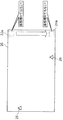
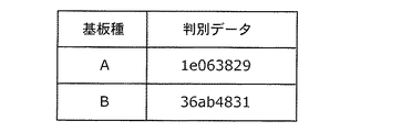
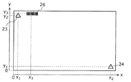
図16A及び図16Bは、基板種判別用データの一例を示す図である。基板種判別用データは、図16Aに示す判別マーク位置データと、図16Bに示す判別データとを含む。ここで、判別マークとは、例えば、図17Aに示されるように、基板20上に設けられたバーコードで示される判別マーク27のことである。図17Aは、基板種Aの基板20の一例を示しており、図17Bは、基板種Bの基板20の一例を示している。基板種Bの基板20にも、同様に判別マーク28が設けられている。これらの判別マーク27(28)の位置は、基板種に共通な位置とする。
16A and 16B are diagrams illustrating an example of substrate type discrimination data. Substrate type discrimination data includes discrimination mark position data shown in FIG. 16A and discrimination data shown in FIG. 16B. Here, the discrimination mark is, for example, a
図16Aに示す判別マーク位置データは、基板種に共通な判別マーク27(28)の位置を示す情報であり、例えば、座標(x3,y3)の位置に判別マーク27(28)が設けられていることが示されている。 The discrimination mark position data shown in FIG. 16A is information indicating the position of the discrimination mark 27 (28) common to the substrate type. For example, the discrimination mark 27 (28) is provided at the position of coordinates (x3, y3). It has been shown that
図16Bに示す判別データは、基板種を判別するための基板種固有のデータである。例えば、基板種Aに固有の判別データは「1e063829」であり、基板種Bに固有の判別データは「36ab4831」である。これらの判別データは、各基板種の判別マーク27(28)のバーコードを読み取ることにより得られるデータである。例えば、図17Aに示される基板種Aの判別マーク27のバーコードを読み取ることにより得られるデータは、基板種Aに固有の判別データ「1e063829」である。
The discrimination data shown in FIG. 16B is data specific to the substrate type for discriminating the substrate type. For example, the discrimination data specific to the board type A is “1e063829”, and the discrimination data specific to the board type B is “36ab4831”. These discrimination data are data obtained by reading the barcode of the discrimination mark 27 (28) of each substrate type. For example, the data obtained by reading the barcode of the
なお、各基板には、判別マークの他に、実施の形態1と同様の基板マークも設けられている。 Each substrate is provided with a substrate mark similar to that of the first embodiment in addition to the discrimination mark.
図18は、部品実装機120による部品実装処理を説明するためのフローチャートである。
FIG. 18 is a flowchart for explaining component mounting processing by the
撮像指示部305b及び仮決定部305dは、部品実装機120に搬入されてきた基板20の判別マークを認識する(S32)。つまり、図19Aに示すように撮像指示部305bは、図16Aの判別マーク位置データで示される判別マークの位置(座標(x3,y3)の位置)へ基板カメラ121bを移動させ、基板カメラ121bによりその位置周辺の領域27aを撮像する。仮決定部305dは、領域27aに含まれる判別マークのバーコードを読み取り、図16Bの判別データと照合することにより、部品実装機120に搬入されてきた基板20の基板種を認識する。
The
認識結果が基板種Aの場合には(S34で基板種A)、仮決定部305dは、部品実装機120に搬入されてきた基板の基板種が、基板種Aであると仮決定する(S2)。仮決定した後は、実施の形態1と同様の処理を行う(S4〜S22)。これらの処理は、実施の形態1で説明したとおりであるため、その詳細な説明はここでは繰り返さない。
When the recognition result is the board type A (board type A in S34), the temporary determination unit 305d temporarily determines that the board type of the board carried into the
なお、図19A、図19B及び図19Bは、基板種A、B及びCの各基板が搬入されてきた場合に、判別マーク認識処理(S32)の認識結果が基板種Aである場合の処理を説明するための図である。 19A, 19B, and 19B show processing when the recognition result of the discrimination mark recognition process (S32) is the substrate type A when the substrates of the substrate types A, B, and C are loaded. It is a figure for demonstrating.
図19Aに示すように、判別マーク27に従い基板種Aの基板を基板種Aと認識した場合には(S34で基板種A)、図15Aに示したのと同様に、基板マーク22及び21の認識が行われ、部品実装機120に搬入された基板20の基板種が基板種Aであると判断される(S2〜S10)。
As shown in FIG. 19A, when the substrate of the substrate type A is recognized as the substrate type A according to the discrimination mark 27 (substrate type A in S34), the substrate marks 22 and 21 are displayed in the same manner as shown in FIG. 15A. Recognition is performed, and it is determined that the board type of the
図19Bに示すように、判別マーク28に従い基板種Bの基板を基板種Aと誤認識した場合には(S34で基板種A)、図15Bに示したのと同様に、領域22aにおいて基板マークの認識に失敗するため(S8でNO)、搬入された基板20の基板種が基板種Bであると仮決定され(S12)、基板マーク24及び23の認識が行われる。その結果、部品実装機120に搬入された基板20の基板種が基板種Bであると判断される(S12〜S20)。
As shown in FIG. 19B, when the substrate type B is erroneously recognized as the substrate type A according to the discrimination mark 28 (substrate type A in S34), the substrate mark is displayed in the
図19Cに示すように、判別マーク29に従い基板種Cの基板を基板種Aと誤認識した場合には(S34で基板種A)、図15Cに示したのと同様に、領域22a及び24aにおいて基板マークの認識に失敗する(S8でNO、S18でNO)。このため、想定外の基板種(基板種A及びB以外の基板種)の基板20が部品実装機120に搬入されたものと判断して、表示部302にエラー表示を行う(S22)。
As shown in FIG. 19C, when the substrate of the substrate type C is erroneously recognized as the substrate type A according to the discrimination mark 29 (substrate type A in S34), in the
一方、認識結果が基板種Bの場合には(S34で基板種B)、搬入された基板20の基板種が基板種Bであると優先的に仮決定され、基板種Bの基板マークの認識が行われた後に、基板種Bの基板マークの認識に失敗した場合には、基板種Aの基板マークの認識処理が行われる(S12〜S20、S2〜S22)。なお、判別マークに従った認識結果が基板種Aの場合と、基板種Bの場合とでは、処理の順序が異なるだけであり、処理の内容は同じである。そのため、その詳細な説明はここでは繰り返さない。
On the other hand, if the recognition result is the substrate type B (substrate type B in S34), the substrate type of the loaded
以上説明したように、本実施の形態によると、基板種毎に基板マークの位置を異ならせ、仮決定した基板種の基板マークの位置における基板マークの有無を検知する。これにより、部品実装機に搬入された基板の基板種が仮決定した基板種と等しいか否かを判断している。基板マークの認識処理は、基板マークの有無のみを検知する処理であるため、基板種の形状を認識する従来の処理に比べて認識精度が高い処理である。このため、基板種の誤判定を起こしにくい。 As described above, according to the present embodiment, the position of the substrate mark is changed for each substrate type, and the presence or absence of the substrate mark at the position of the substrate mark of the temporarily determined substrate type is detected. Thus, it is determined whether or not the board type of the board carried into the component mounter is equal to the provisionally determined board type. The substrate mark recognition process is a process that detects only the presence or absence of a substrate mark, and is therefore a process with higher recognition accuracy than the conventional process for recognizing the shape of a substrate type. For this reason, it is difficult to cause erroneous determination of the substrate type.
また、実施の形態1では、仮決定する基板種を予め定められた優先順位に従って決定している。このため、優先順位が高い基板種の基板が搬入されてきた場合には、早期に基板マークの認識に成功し、基板種を決定することができるが、優先順位が低い基板種の基板が搬入されてきた場合には、基板マークの認識に失敗した後に、基板マークの認識に成功するため、早期に基板種を決定することができない。しかし、実施の形態2では、判別マークの認識を行い、その結果に基づいて、基板種の仮決定を行うことにより、搬入が想定されているいずれの基板種の基板が搬入されたとしても、早期に基板種を決定することができる。 In the first embodiment, the tentatively determined substrate type is determined according to a predetermined priority order. For this reason, when a board of a board type with a high priority is carried in, the board mark can be recognized early and the board type can be determined, but a board of a board type with a low priority is carried in. In the case where the substrate mark has been recognized, the substrate mark is successfully recognized after failing to recognize the substrate mark, so that the substrate type cannot be determined at an early stage. However, in the second embodiment, the recognition mark is recognized, and the substrate type is provisionally determined based on the result, so that no matter which substrate type is supposed to be loaded, The substrate type can be determined at an early stage.
以上、本発明の実施の形態に係る部品実装機について説明したが、本発明は、これらの実施の形態に限定されるものではない。 As mentioned above, although the component mounting machine which concerns on embodiment of this invention was demonstrated, this invention is not limited to these embodiment.
例えば、実施の形態1では、搬入される基板の基板種を生産枚数の計画値が多い基板種に優先的に仮決定するように、仮決定する基板種の優先順序を決定しているが、優先順位の決定方法はこれに限定されるものではない。基板1枚あたりの部品実装時間が長い基板種ほど順位が高くなるように優先順位を決定してもよい。これにより、部品実装時間が長い基板種ほど基板種を識別するのに要する時間を短くすることができる。よって、基板種識別に要する時間を含めた実装基板を生産するのに要する合計時間のばらつきを基板種間で少なくすることができる。 For example, in the first embodiment, the priority order of the substrate types to be provisionally determined is determined so as to preferentially determine the substrate types of the substrates to be carried in preferentially to the substrate types having a large number of production values. The method for determining the priority order is not limited to this. The priority order may be determined such that the higher the order of the board types, the longer the component mounting time per board. Thereby, the time required to identify the board type can be shortened as the board type has a longer component mounting time. Therefore, it is possible to reduce the variation in the total time required for producing the mounting board including the time required for the board type identification among the board types.
また、実施の形態2では、判別マークとしてバーコードを用いたが、基板種を識別できるマークであれば、これに限られるものではなく、QRコード(登録商標)や、位置や並びによって基板種を識別するための判別マークなどであってもよい。さらに、基板種毎に形状、寸法又は色が異なるマークを、基板種を識別するための判別マークとして用いてもよい。 In the second embodiment, a barcode is used as a discrimination mark. However, the barcode is not limited to this as long as it is a mark that can identify the substrate type, and the substrate type is determined depending on the QR code (registered trademark), position, and arrangement. It may be a discrimination mark for identifying the. Further, a mark having a different shape, size, or color for each substrate type may be used as a discrimination mark for identifying the substrate type.
また、本発明は、部品実装機以外であっても、基板種を識別することが必要な装置に適用することができ、例えば、半田印刷機、接着剤塗布機、リフロー炉などに適用することもできる。 Further, the present invention can be applied to an apparatus that needs to identify a substrate type even if it is not a component mounting machine, and is applied to, for example, a solder printing machine, an adhesive application machine, a reflow furnace, etc. You can also.
今回開示された実施の形態はすべての点で例示であって制限的なものではないと考えられるべきである。本発明の範囲は上記した説明ではなくて特許請求の範囲によって示され、特許請求の範囲と均等の意味及び範囲内でのすべての変更が含まれることが意図される。 The embodiment disclosed this time should be considered as illustrative in all points and not restrictive. The scope of the present invention is defined by the terms of the claims, rather than the description above, and is intended to include any modifications within the scope and meaning equivalent to the terms of the claims.
本発明は、基板上に部品を実装する部品実装機等に適用できる。 The present invention can be applied to a component mounter for mounting components on a substrate.
20 基板
21〜26 基板マーク
21a〜24a、27a 領域
27〜29 判別マーク
107 部品リール
120 部品実装機
120a 前サブ設備
120b 後サブ設備
121 装着ヘッド
121a 吸着ノズル
121b 基板カメラ
122 ビーム
123 部品カセット
125a、125b 部品供給部
126 部品認識カメラ
127 ノズルチェンジャ
129 レール
129a 固定レール
129b 可動レール
131 機構部
132 機構制御部
302 表示部
303 入力部
304 メモリ部
305a 取得部
305b 撮像指示部
305c 判断部
305d 仮決定部
307 データベース部
307a 実装点データ
307b 部品ライブラリ
307c 実装装置情報
307d 実装点数情報
307e 基板マークデータ
307f 生産枚数データ
20 Substrate 21-26
Claims (8)
搬入された基板の基板種が、所定の基板種であると仮決定する仮決定ステップと、
仮決定した前記所定の基板種の基板に付される基板マークの位置であって、基板種固有の位置を示す位置情報を取得する取得ステップと、
基板の搬入時に、前記位置情報で特定される位置へ、前記基板マークを認識するための基板カメラを移動させ、前記基板カメラにより当該位置を撮像する撮像ステップと、
前記撮像ステップで得られた画像に基づいて、前記位置情報で特定される位置における前記基板マークの有無を検知し、前記基板マークが有ると検知された場合には、搬入された前記基板の基板種が、仮決定した前記所定の基板種と同じであると判断する判断ステップと
を含む基板種識別方法。 A board type identification method for identifying a board type of a board carried into a component mounting machine,
A provisional determination step for provisionally determining that the substrate type of the loaded substrate is a predetermined substrate type;
An acquisition step of acquiring position information indicating a position specific to a substrate type, which is a position of a substrate mark attached to a substrate of the predetermined substrate type that is provisionally determined;
An imaging step of moving a substrate camera for recognizing the substrate mark to a position specified by the position information when the substrate is carried in, and imaging the position by the substrate camera;
Based on the image obtained in the imaging step, the presence / absence of the substrate mark at the position specified by the position information is detected, and when the substrate mark is detected, the substrate of the substrate carried in is detected. And a determination step of determining that the type is the same as the predetermined predetermined substrate type.
前記仮決定ステップにおいて前記他の基板種に仮決定しなおされた場合には、前記取得ステップ、前記撮像ステップ及び前記判断ステップを再度実行する
請求項1記載の基板種識別方法。 In the provisional determination step, when it is detected that the substrate mark is not present in the determination step, the substrate type of the carried-in substrate is another substrate type different from the predetermined substrate type that has been provisionally determined. Tentatively determined to be
The substrate type identification method according to claim 1, wherein if the other substrate type is provisionally determined in the temporary determination step, the acquisition step, the imaging step, and the determination step are executed again.
請求項2記載の基板種識別方法。 The substrate type identification method according to claim 2, wherein, in the provisional determination step, the substrate type of the loaded substrate is provisionally determined in accordance with a predetermined priority order of the substrate types.
請求項3記載の基板種識別方法。 The substrate type identification method according to claim 3, wherein the priority order of the predetermined substrate type is a priority level that becomes higher as the substrate type has a larger production value.
請求項3記載の基板種識別方法。 The board type identification method according to claim 3, wherein the priority order of the predetermined board types is a higher priority level for board types having a longer component mounting time per board.
請求項1又は請求項2記載の基板種識別方法。 In the initial provisional decision in the provisional decision step, the substrate camera recognizes a discrimination mark attached to the substrate and unique to the substrate type when the substrate is loaded, and the loading is performed based on a recognition result. The substrate type identification method according to claim 1, wherein the substrate type of the obtained substrate is provisionally determined.
搬入された基板の基板種が、所定の基板種であると仮決定する仮決定部と、
仮決定した前記所定の基板種の基板に付される基板マークの位置であって、基板種固有の位置を示す位置情報を取得する取得部と、
基板の搬入時に、前記位置情報で特定される位置へ前記基板カメラを移動させ、前記基板カメラにより当該位置を撮像させる撮像指示部と、
前記基板カメラにより得られた画像に基づいて、前記位置情報で特定される位置における前記基板マークの有無を検知し、前記基板マークが有ると検知された場合には、搬入された前記基板の基板種は、仮決定した前記所定の基板種と同じであると判断する判断部と
を備える部品実装機。 A component mounting machine including a board camera for recognizing a board mark attached to a board,
A provisional determination unit that provisionally determines that the substrate type of the loaded substrate is a predetermined substrate type;
An acquisition unit that acquires position information indicating a position specific to a substrate type, which is a position of a substrate mark attached to the substrate of the predetermined substrate type that is provisionally determined;
An imaging instruction unit that moves the substrate camera to a position specified by the position information and images the position by the substrate camera when the substrate is loaded;
Based on the image obtained by the substrate camera, the presence / absence of the substrate mark at the position specified by the position information is detected, and when the substrate mark is detected, the substrate of the substrate carried in is detected. A component mounting machine comprising: a determination unit that determines that the seed is the same as the predetermined board type that has been provisionally determined.
搬入された基板の基板種が、所定の基板種であると仮決定する仮決定ステップと、
仮決定した前記所定の基板種の基板に付される基板マークの位置であって、基板種固有の位置を示す位置情報を取得する取得ステップと、
基板の搬入時に、前記位置情報で特定される位置へ、前記基板マークを認識するためのカメラを移動させ、前記基板カメラにより当該位置を撮像する撮像ステップと、
前記撮像ステップで得られた画像に基づいて、前記位置情報で特定される位置における前記基板マークの有無を検知し、前記基板マークが有ると検知された場合には、搬入された前記基板の基板種は、仮決定した前記所定の基板種と同じであると判断する判断ステップと
をコンピュータに実行させるためのプログラム。 A program for identifying a board type of a board carried into a component mounter,
A provisional determination step for provisionally determining that the substrate type of the loaded substrate is a predetermined substrate type;
An acquisition step of acquiring position information indicating a position specific to a substrate type, which is a position of a substrate mark attached to a substrate of the predetermined substrate type that is provisionally determined;
An imaging step of moving a camera for recognizing the substrate mark to a position specified by the position information when the substrate is carried in, and imaging the position by the substrate camera;
Based on the image obtained in the imaging step, the presence / absence of the substrate mark at the position specified by the position information is detected, and when the substrate mark is detected, the substrate of the substrate carried in is detected. A program for causing a computer to execute a determination step of determining that the seed is the same as the predetermined predetermined substrate type.
Priority Applications (1)
| Application Number | Priority Date | Filing Date | Title |
|---|---|---|---|
| JP2008315814A JP2010141118A (en) | 2008-12-11 | 2008-12-11 | Substrate type discriminating method, part mounter, and program |
Applications Claiming Priority (1)
| Application Number | Priority Date | Filing Date | Title |
|---|---|---|---|
| JP2008315814A JP2010141118A (en) | 2008-12-11 | 2008-12-11 | Substrate type discriminating method, part mounter, and program |
Publications (1)
| Publication Number | Publication Date |
|---|---|
| JP2010141118A true JP2010141118A (en) | 2010-06-24 |
Family
ID=42350990
Family Applications (1)
| Application Number | Title | Priority Date | Filing Date |
|---|---|---|---|
| JP2008315814A Pending JP2010141118A (en) | 2008-12-11 | 2008-12-11 | Substrate type discriminating method, part mounter, and program |
Country Status (1)
| Country | Link |
|---|---|
| JP (1) | JP2010141118A (en) |
Cited By (1)
| Publication number | Priority date | Publication date | Assignee | Title |
|---|---|---|---|---|
| JP2013045940A (en) * | 2011-08-25 | 2013-03-04 | Yamaha Motor Co Ltd | Method for detecting identification information, substrate processing apparatus, substrate processing system and computer program |
Citations (3)
| Publication number | Priority date | Publication date | Assignee | Title |
|---|---|---|---|---|
| JPH08242095A (en) * | 1995-03-06 | 1996-09-17 | Yamaha Motor Co Ltd | Mounting method of mounting machine |
| JPH11298189A (en) * | 1998-04-06 | 1999-10-29 | Omron Corp | Setup change method and apparatus |
| JP2008263138A (en) * | 2007-04-13 | 2008-10-30 | Matsushita Electric Ind Co Ltd | Mounting condition determination method |
-
2008
- 2008-12-11 JP JP2008315814A patent/JP2010141118A/en active Pending
Patent Citations (3)
| Publication number | Priority date | Publication date | Assignee | Title |
|---|---|---|---|---|
| JPH08242095A (en) * | 1995-03-06 | 1996-09-17 | Yamaha Motor Co Ltd | Mounting method of mounting machine |
| JPH11298189A (en) * | 1998-04-06 | 1999-10-29 | Omron Corp | Setup change method and apparatus |
| JP2008263138A (en) * | 2007-04-13 | 2008-10-30 | Matsushita Electric Ind Co Ltd | Mounting condition determination method |
Cited By (1)
| Publication number | Priority date | Publication date | Assignee | Title |
|---|---|---|---|---|
| JP2013045940A (en) * | 2011-08-25 | 2013-03-04 | Yamaha Motor Co Ltd | Method for detecting identification information, substrate processing apparatus, substrate processing system and computer program |
Similar Documents
| Publication | Publication Date | Title |
|---|---|---|
| JP2006245483A (en) | Method of mounting components and device for mounting components using same | |
| WO2015045002A1 (en) | Mounting apparatus | |
| JP5683006B2 (en) | Component mounting apparatus, information processing apparatus, information processing method, and board manufacturing method | |
| JP2002525884A (en) | Component supply method, component supply device, component mounting method, and component mounting device | |
| JP4580972B2 (en) | Component mounting method | |
| JP5190127B2 (en) | Substrate processing equipment | |
| JP2012043886A (en) | Component verifying method and device | |
| JP2012134303A (en) | Electronic component attachment device, and electronic component attachment method | |
| JP2010141118A (en) | Substrate type discriminating method, part mounter, and program | |
| JP2001036297A (en) | Component mounting apparatus | |
| JP2009123902A (en) | Component mounting condition determining method, component mounting condition determining apparatus, and program | |
| JP2000022392A (en) | Electronic component placement management device for mounting machines | |
| JP4555118B2 (en) | Component mounting apparatus and component holding member discrimination method | |
| JPH1154993A (en) | Component mounting device | |
| JP4907493B2 (en) | Mounting condition determining method and mounting condition determining apparatus | |
| JP7235603B2 (en) | Component mounting data change device, change program, and surface mounter | |
| JP2020034362A (en) | Recognition device, surface mounter, and position recognition method for recognition target | |
| US11219150B2 (en) | Work machine and method for determining polarity | |
| JP6055665B2 (en) | Electronic component mounting method and surface mounter | |
| KR102482117B1 (en) | Method for extracting mounting position of surface mount | |
| JP4891156B2 (en) | Nozzle discrimination method | |
| JPH1140999A (en) | Electronic component mounting method for multiple board | |
| JP2010129889A (en) | Mounting condition decision method, mounting condition decision device, component mounting machine, and program | |
| WO2020183515A1 (en) | Information processing device | |
| JP4937177B2 (en) | Board component manual mounting equipment |
Legal Events
| Date | Code | Title | Description |
|---|---|---|---|
| A621 | Written request for application examination |
Free format text: JAPANESE INTERMEDIATE CODE: A621 Effective date: 20110221 |
|
| A977 | Report on retrieval |
Free format text: JAPANESE INTERMEDIATE CODE: A971007 Effective date: 20120417 |
|
| A131 | Notification of reasons for refusal |
Free format text: JAPANESE INTERMEDIATE CODE: A131 Effective date: 20120424 |
|
| A521 | Written amendment |
Free format text: JAPANESE INTERMEDIATE CODE: A523 Effective date: 20120531 |
|
| A02 | Decision of refusal |
Free format text: JAPANESE INTERMEDIATE CODE: A02 Effective date: 20120619 |