JP2010111368A - Door end rubber for vehicle door - Google Patents
Door end rubber for vehicle door Download PDFInfo
- Publication number
- JP2010111368A JP2010111368A JP2008288106A JP2008288106A JP2010111368A JP 2010111368 A JP2010111368 A JP 2010111368A JP 2008288106 A JP2008288106 A JP 2008288106A JP 2008288106 A JP2008288106 A JP 2008288106A JP 2010111368 A JP2010111368 A JP 2010111368A
- Authority
- JP
- Japan
- Prior art keywords
- door
- rubber
- vehicle
- side wall
- dimension
- Prior art date
- Legal status (The legal status is an assumption and is not a legal conclusion. Google has not performed a legal analysis and makes no representation as to the accuracy of the status listed.)
- Granted
Links
- 229920001971 elastomer Polymers 0.000 title claims abstract description 82
- 239000005060 rubber Substances 0.000 title claims abstract description 81
- 239000010410 layer Substances 0.000 claims description 19
- 239000002783 friction material Substances 0.000 claims description 16
- 239000007787 solid Substances 0.000 claims description 7
- 239000002344 surface layer Substances 0.000 claims description 4
- 238000001514 detection method Methods 0.000 abstract description 10
- 230000035945 sensitivity Effects 0.000 abstract description 8
- 230000000052 comparative effect Effects 0.000 description 13
- 239000002184 metal Substances 0.000 description 7
- 238000012360 testing method Methods 0.000 description 5
- 208000034656 Contusions Diseases 0.000 description 2
- 208000027418 Wounds and injury Diseases 0.000 description 2
- 208000034526 bruise Diseases 0.000 description 2
- 230000006378 damage Effects 0.000 description 2
- 230000007423 decrease Effects 0.000 description 2
- 238000010586 diagram Methods 0.000 description 2
- 208000014674 injury Diseases 0.000 description 2
- 235000010724 Wisteria floribunda Nutrition 0.000 description 1
- 238000009530 blood pressure measurement Methods 0.000 description 1
- 238000006243 chemical reaction Methods 0.000 description 1
- 239000000806 elastomer Substances 0.000 description 1
- 238000000605 extraction Methods 0.000 description 1
- 239000000463 material Substances 0.000 description 1
- 238000005259 measurement Methods 0.000 description 1
- 238000012986 modification Methods 0.000 description 1
- 230000004048 modification Effects 0.000 description 1
- 230000003287 optical effect Effects 0.000 description 1
- 230000000704 physical effect Effects 0.000 description 1
- 229920001084 poly(chloroprene) Polymers 0.000 description 1
- -1 polytetrafluoroethylene Polymers 0.000 description 1
- 229920001343 polytetrafluoroethylene Polymers 0.000 description 1
- 239000004810 polytetrafluoroethylene Substances 0.000 description 1
- 239000011347 resin Substances 0.000 description 1
- 229920005989 resin Polymers 0.000 description 1
- 238000007789 sealing Methods 0.000 description 1
- 238000009751 slip forming Methods 0.000 description 1
- 230000009466 transformation Effects 0.000 description 1
Images

Landscapes
- Specific Sealing Or Ventilating Devices For Doors And Windows (AREA)
Abstract
【課題】戸先ゴムの断面形状を工夫して引抜性と検知感度とを向上させる。
【解決手段】戸先ゴムの側壁部に側溝を設け、戸先ゴムが車内外方向で撓み変形しやすくする。戸先ゴムの当たり面に物が挟まれた場合、車外側または車内側に容易に引き抜くことができる。当たり面は平坦部とすることにより、物が挟まれ戸閉め力が作用しても、その力は戸先ゴムの側壁部および中央突起部に分散させ、挟み物に加わる最大圧力を低減する。さらに、中空部を扉の戸閉め方向の寸法を短かく、車両の内外方向の寸法を長く形成し、ゴム変形を小さくして扉間隔が大きくなることで検知感度を向上させる。
【選択図】 図3[PROBLEMS] To improve the pullability and detection sensitivity by devising the cross-sectional shape of a door rubber.
A side groove is provided in a side wall portion of the door-end rubber so that the door-end rubber is easily bent and deformed in the vehicle interior / exit direction. When an object is sandwiched between the contact surfaces of the door-end rubber, it can be easily pulled out to the outside or inside of the vehicle. By making the contact surface flat, even if an object is pinched and a door closing force is applied, the force is distributed to the side wall portion and the central protrusion of the door rubber, and the maximum pressure applied to the pinched object is reduced. Further, the detection sensitivity is improved by forming the hollow portion with a short door closing dimension and a long vehicle inner and outer dimension, reducing rubber deformation and increasing the door interval.
[Selection] Figure 3
Description
本発明は、鉄道車両等の乗降扉の戸先に設置される車両用の戸先ゴムに関するものである。 The present invention relates to a door rubber for a vehicle installed at a door of a passenger door such as a railway vehicle.
この種の戸先ゴムに要求される特性として、乗降扉の閉姿勢におけるシール性は勿論のこと、乗客や物が挟まれたことを検知できる検知性と、乗客や物が挟まれたときに引き抜きやすくする引抜性なども要求される。 As a characteristic required for this kind of door rubber, not only the sealing performance in the closed position of the passenger door, but also the detectability that can detect that a passenger or an object is caught, and when the passenger or an object is caught Pullability that facilitates drawing is also required.
特許文献1には、戸先ゴムに空気室が設けられ、該戸先ゴムをその長手方向に直交する平面で切った時の該空気室の断面形状は半円状であって、該半円形状の空気室は戸先ゴムの車内側に配置され、戸先ゴムの車外側は中実であり、該空気室は圧力センサが設けられた空間に連通するようにした乗降扉用戸先ゴムが開示されている。
In
この戸先ゴムによると、空気室の車外側は中実であるので、乗降扉に挟まれた物を車外のプラットフォーム側から引っ張ると、戸先ゴムの車内側が圧迫されて半円形状の空気室が変形し、空気室の圧力上昇により圧力センサを通じて戸挟みの検知が容易に行える。一方、乗降扉に挟まれた物を車内側から引っ張られると、戸先ゴムの車外側が圧迫されてが、戸先ゴムの車外側は中実であるので、空気室は少ししか変形せず、戸挟み感度が鈍感となる。
ところで、戸先ゴムに要求される検知性と引抜性については、その形態を工夫してさらなる向上を目指す要求がなされている。 By the way, about the detectability and pulling-out property requested | required of door-end rubber, the request | requirement aiming at the further improvement by devising the form is made | formed.
本発明は、上記に鑑み、断面形状を工夫することにより、引抜性を向上させること、さらには、検知感度を向上させることを目的としている。 In view of the above, an object of the present invention is to improve the pullability and further improve the detection sensitivity by devising the cross-sectional shape.
上記目的を達成するため、本発明は、中空部を有する車両の引き戸式乗降扉の戸先ゴムであって、側壁部に戸先ゴムの撓み変形しやすくするための側溝が形成されたことを特徴とする。 In order to achieve the above object, the present invention is a door-end rubber of a sliding door type entrance door for a vehicle having a hollow portion, and a side groove for facilitating the deformation of the door-end rubber is formed in a side wall portion. Features.
上記構成によると、戸先ゴムの当たり面に物が挟まれた場合、車外または車内に引き抜こうとするが、このとき、戸先ゴムの側壁部に側溝を設けておくと、戸先ゴムが車内外方向で撓み変形しやすくなる。そのため、挟み物が引き抜きやすくなる。 According to the above configuration, when an object is caught in the contact surface of the door rubber, it tries to be pulled out of the vehicle or inside the vehicle. At this time, if a side groove is provided on the side wall of the door rubber, the door rubber is It becomes easy to bend and deform in the inner and outer directions. Therefore, it becomes easy to pull out the sandwiched article.
また、上記構成に加えて、戸先ゴムの当たり面が平坦部とされ、該平坦部の背面側に中空部が形成され、該中空部の戸先ゴムの基部側に前記平坦部に対向してゴム突起が突出形成された構成を採用することができる。 Further, in addition to the above configuration, the contact surface of the door rubber is a flat part, a hollow part is formed on the back side of the flat part, and the flat part is opposed to the flat part on the base side of the door rubber of the hollow part. Thus, it is possible to employ a configuration in which rubber protrusions are formed to protrude.
この構成によると、当たり面が平坦部であるため、手や指が戸先間に挟まされたとしても、戸閉め力が側壁部および中央突起部に分散する。その結果、挟み物に加わる最大圧力が低減され、打撲などの傷害を防ぐことができる。 According to this structure, since the contact surface is a flat part, even if a hand or a finger is pinched between the door tips, the door closing force is distributed to the side wall part and the central protrusion part. As a result, the maximum pressure applied to the pinch is reduced, and injury such as bruise can be prevented.
また、中空部は、扉の戸閉め方向の寸法が車両の内外方向の寸法よりも短く形成されている。これにより、物が戸先に挟まれて戸閉め力が作用しても、ゴム変形が小さく、扉間隔が大きくなることで検知感度を向上させることができる。 Moreover, the hollow part is formed so that the dimension of the door closing direction of the door is shorter than the dimension of the vehicle inside / outside direction. Thereby, even if an object is pinched | interposed into a door tip and a door closing force acts, rubber | gum deformation | transformation is small and detection sensitivity can be improved because a door space | interval becomes large.
さらに、当たり面の表層には低摩擦材層を形成することができる。これにより、物が挟まれた場合でも小さな引き抜き力で引く抜くことができる。 Furthermore, a low friction material layer can be formed on the surface layer of the contact surface. Thereby, even when an object is pinched, it can be pulled out with a small pulling force.
なお、基部は中実に形成され、側溝は基部の側壁部に上下方向で凹条に形成される。この構成によると、中実状の基部も撓み変形が容易に行える。しかも、側壁部に側溝があるため、扉構体への戸先ゴムの挿入あるいは位置合わせ作業時に手指を側溝に掛けて作業を行うことができ、組付け作業性を向上させることができる。 The base is formed solid, and the side groove is formed in a concave line in the vertical direction on the side wall of the base. According to this configuration, the solid base portion can be easily bent and deformed. In addition, since there is a side groove on the side wall, the work can be performed with fingers placed on the side groove when inserting or positioning the door-end rubber into the door structure, and the assembly workability can be improved.
なお、側溝は、所望の引抜力に応じて、扉の開閉方向で複数条形成することができる。 Note that a plurality of side grooves can be formed in the opening and closing direction of the door according to a desired pulling force.
また、低摩擦材層としてはフッ素樹脂から構成されるものを例示することができる。 Moreover, as a low friction material layer, what is comprised from a fluororesin can be illustrated.
本発明によると、戸先ゴムの側壁部に側溝を設けて戸先ゴムが車内外方向で撓み変形しやすくしているので、戸先ゴムの当たり面に物が挟まれた場合、車外側または車内側に容易に引き抜くことができ、引抜性に優れた安全性に高い戸先ゴムを提供することができる。また、当たり面に平坦部を形成することにより、物が挟まれ、戸閉め力が作用しても、その力は戸先ゴムの側壁部および中央突起部に分散し、挟み物に加わる最大圧力を低減する。さらに、中空部を扉の開閉方向の左右方向寸法よりも車両の内外方向の寸法が長く形成すると、ゴム変形が小さく、扉間隔が大きくなることで検知感度を向上させることができる。 According to the present invention, since the side rubber is provided in the side wall portion of the door rubber so that the door rubber is bent and deformed easily in the vehicle interior / exterior direction, when an object is sandwiched between the contact surfaces of the door rubber, It is possible to provide a door rubber that can be easily pulled out to the inside of the vehicle and has excellent pullability and high safety. In addition, by forming a flat portion on the contact surface, even if an object is pinched and a door closing force is applied, the force is distributed to the side wall portion and the central protrusion of the door rubber, and the maximum pressure applied to the pinched object Reduce. Further, if the hollow portion is formed to have a longer dimension in the vehicle inner / outer direction than the dimension in the left / right direction of the door opening / closing direction, the rubber deformation is small and the door spacing is increased, so that the detection sensitivity can be improved.
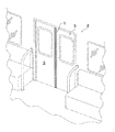
以下、本発明の実施形態を図面に基づいて説明する。図11は本発明の実施形態を示す鉄道車両の乗降扉を示す斜視図、図2は引き戸式の乗降扉に物が挟まった状態を示す概略正面図、図3は乗降扉の閉状態における戸先ゴムの断面図である。 Hereinafter, embodiments of the present invention will be described with reference to the drawings. FIG. 11 is a perspective view showing a passenger door of a railway vehicle showing an embodiment of the present invention, FIG. 2 is a schematic front view showing a state in which an object is sandwiched between sliding door type passenger doors, and FIG. 3 is a door in a closed state of the passenger door It is sectional drawing of a tip rubber.
図1,2において、戸先ゴム1は、鉄道車両2の引き戸式乗降扉3の扉構体3aの戸先3bに取り付けられ、扉の閉状態で互いに接触してシールするものである。
1 and 2, the
乗降扉3は、戸閉め力が作用して扉が閉状態になると、扉構体3aに取り付けられた接触子19が車体側に設置された戸閉まり感知スイッチ18をオンすることで乗降扉3の閉状態を感知できるようになっている。
When the door closes due to the door closing force acting on the
万一、戸先ゴム1間に挟み物20を挟んだ場合、感知スイッチ18がオフ状態であるので、戸閉まりを感知せず、鉄道車両の発車が制限されることになる。
In the unlikely event that the
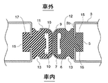
戸先ゴム1は、乗降扉3の戸先3bに取り付けられる取付部5と、戸先の対向面側に配置される基部6と、該基部よりも先端側に配置される当たり部7とを備えている。
The door-
戸先ゴム1は、その上下方向で横断面形状が同一であり、クロロプレンゴム等のゴム状弾性体により押し出し成形されてなる。ゴム状弾性体は、ゴム以外の樹脂エラストマーであってもよいことは勿論である。
The
取付部5は、断面四角状に形成され、扉構体3aの戸先内部に形成された取付凹部15に、上方から差し込み可能に装着される。取付部5と基部6とは幅狭の連結部16で連結される。連結部16は、扉構体3aの戸先3bに形成されたスリット17に嵌合される。これにより、取付部5は、扉構体3aから抜け出ないようになっている。
The
当たり部7は、表面側の当たり面が平坦な平坦部9とされ、背面側に中空部10が形成されている。平坦部9は、車両の内外方向の全体幅に対して半分以上の幅で平坦面とされる。
The
中空部10は、扉の戸閉め方向の寸法が車両の内外方向の寸法よりも短く形成されている。中空部10は、当たり部7において、内外方向にほぼ全域にわたって長く形成されると共に、戸閉め方向には小さく形成される。例えば、戸先ゴムの扉構体からの露出高さが15mmのとき、中空部10の内寸法が3mm程度に設定される。
The
中空部10の戸先ゴムの基部6側には前記平坦部9に対向してゴム突起12が突出形成されている。突起12は、車両の内外方向に長く中空部10のほぼ1/2程度の長さに設定されている。また、突起12の高さは、中空部の扉開閉方向の長さに対してほぼ1/3程度に設定されている。戸閉め力が作用してもゴムの変形が小さくなるように設定されている。
On the
当たり部7の表層には低摩擦材層11が形成され、物が挟まれた場合でも小さな引抜き力で引き抜くことができるようになっている。この低摩擦材層11は、材料としては特に限定されないが、フッ素樹脂、例えば、ポリテトラフルオロエチレンから構成することができる。低摩擦材層11の層厚は特に限定されず、所望の表面摩擦係数を継続維持できる程度の層厚であればよい。図3において、低摩擦材層11は、当たり部7の表面にのみ形成したが、基部6の側壁部に及ぶ露出部分全体に形成してもよい。
A low-
基部6は、中空部10よりも扉の戸先側で全体の3/5程度の高さを占める。基部6は、中実に形成され、その側壁部に戸先ゴム1の撓み変形をしやすくするための側溝13が上下方向に連続して形成されている。側溝13は、半円状の断面凹形状に形成される。
The
本実施形態では、側溝13は車両の内外で、基部6の側壁部にそれぞれ1条づつ形成しているが、その条数はこれに限らず、所望の引抜き力を得るために2条以上の複数条の側溝を形成してもよいことは勿論である。
In the present embodiment, the
上記構成において、戸先ゴム1の当たり面に物20が挟まれ、これを車外または車内方向に引き抜こうとした場合、戸先ゴム1の側壁部に側溝13を設けているので、戸先ゴム1が車内外方向で撓み変形しやすくなる。そのため、挟み物20が引き抜きやすくなる。
In the above configuration, when the
また、戸先3bに手や指が挟まれた場合でも、当たり部7が平坦部9とされているため、戸閉め力が基部6の側壁部および中央突起部12に分散することになる。その結果、挟み物20に加わる最大圧力が低減され、打撲などの傷害を防ぐことができる。
Even when a hand or a finger is sandwiched between the
また、中空部10は、扉の戸閉め方向寸法よりも車両の内外方向の寸法が長く形成されている。言い換えると、扉の戸閉め方向の寸法が車両の内外方向の寸法よりも短く形成されているので、物20が戸先3bに挟まれて戸閉め力が作用しても、ゴム変形が小さく、乗降扉3の間隔が大きくなることで、感知スイッチ18が作動せず、戸閉まりを検知しなくなる。そのため、戸先ゴム1の検知感度を向上させることができる。
Moreover, the
さらに、当たり部7の表層には低摩擦材層11が形成されているので、物20が挟まれた場合でも小さな引き抜き力で引く抜くことができる。
Furthermore, since the low
なお、基部6には、側溝13があるため、扉構体3aへの戸先ゴム1の挿入あるいは位置合わせ作業時に手指を側溝13に掛けて組付け作業性を容易に行うことができる。
In addition, since the
次に、本発明の実施例1,2および比較例1,2について検知性および引抜性を対比すると表1のようになる。このときの条件は図4および図5に示す通りである。 Next, Table 1 shows a comparison of the detectability and the pullability of Examples 1 and 2 and Comparative Examples 1 and 2 of the present invention. The conditions at this time are as shown in FIGS.
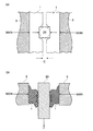
図4(a)は本実施例の戸先ゴムの平面図、同図(b)は比較例の戸先ゴムの平面図である。ただし、いずれも低摩擦材層を省略した図になっている。また、同じ条件で試験できるように、戸先ゴムの高さや幅寸法を同一条件とするなど、図示の寸法(単位はmm)の戸先ゴムを準備した。図5(a)は戸先ゴムの検知性を試験するための条件を示す図、同図(b)は挟み物20の引抜性を試験するための条件を示す図である。
FIG. 4A is a plan view of the door rubber of this embodiment, and FIG. 4B is a plan view of the door rubber of the comparative example. However, in each case, the low friction material layer is omitted. In addition, door rubber having the dimensions shown (unit: mm) was prepared such that the height and width of the door rubber were the same so that the test could be performed under the same conditions. FIG. 5A is a diagram showing conditions for testing the detectability of door rubber, and FIG. 5B is a diagram showing conditions for testing the pullability of the sandwiched
図5(a)において、挟み物20は、直径20mmの金属丸棒と、20mm角の金属角棒を準備し、戸閉め力は両側から500Nの押圧力を作用させ、そのときの戸先ゴム1間の隙間寸法Cを測定した。
In FIG. 5 (a), the
また、図5(b)において、挟み物20を戸閉め力を両側から500Nの押圧力で押圧させた状態で、車外方向に引き抜いたときの引抜力を測定した。
Further, in FIG. 5B, the pulling force when the pinching
比較例1および実施例1は、低摩擦材層が形成されていない戸先ゴムであり、比較例2および実施例2は、低摩擦材層としてフッ素樹脂層を形成した戸先ゴムである。 Comparative Example 1 and Example 1 are door rubbers in which a low friction material layer is not formed, and Comparative Examples 2 and 2 are door rubbers in which a fluororesin layer is formed as a low friction material layer.

表1に示すように、20mmの金属角棒を挟み物として検知性を測定した場合、隙間寸法Cが比較例1,2では3.9mm、3.8mmであるのに対し、実施例1では11.0mm、実施例2では10.1mmと大幅に広くなる。また、20mmの金属丸棒を挟み物として検知性を測定した場合も同様に、隙間寸法Cが比較例1,2では0.3mm、0.0mmであるのに対し、実施例1では7.0mm、実施例2では5.9mmと大幅に広くなる。したがって、本実施例の場合、物が挟まれたときの検知感度が向上するといった結果が得られた。 As shown in Table 1, when the detectability was measured using a 20 mm metal square bar as a sandwich, the gap size C was 3.9 mm and 3.8 mm in Comparative Examples 1 and 2, whereas in Example 1, 11.0 mm, and in Example 2, the width is greatly widened to 10.1 mm. Similarly, when the detectability is measured using a 20 mm metal round bar as a sandwich, the gap dimension C is 0.3 mm and 0.0 mm in Comparative Examples 1 and 2, whereas in Example 1, 7. In Example 2, the width is significantly widened to 0 mm and 5.9 mm. Therefore, in the case of the present Example, the result that the detection sensitivity when an object was pinched improved was obtained.
また、20mmの金属角棒を挟み物として引抜性を測定した場合、比較例1では200N以上、比較例2では119Nであるのに対し、実施例1では150N、実施例2では109Nと大幅に引き抜き力が低下する。 Also, when the pullability was measured with a 20 mm metal square bar as a sandwich, the comparative example 1 was 200 N or more, the comparative example 2 was 119 N, the first example was 150 N, and the second example was 109 N. Pull-out force decreases.
また、20mmの金属丸棒を挟み物として引抜性を測定した場合も同様に、比較例1では200N以上、比較例2では130Nであるのに対し、実施例1では127N、実施例2では118Nと大幅に引抜力が低下する。したがって、本実施例の場合、物が挟まれたときの引抜力が低下するといった結果が得られた。 Similarly, when the pullability is measured using a 20 mm metal round bar as a sandwich, it is 200 N or more in Comparative Example 1 and 130 N in Comparative Example 2, whereas it is 127 N in Example 1 and 118 N in Example 2. And the pulling force is greatly reduced. Therefore, in the case of the present Example, the result that the extraction force when an object was pinched fell was obtained.
また、直径20mmの金属丸棒を挟み物として、これに予め圧力測定フイルム(例えば、富士フイルム製 商品名:プレスケール)を巻き付けた後、戸先ゴムに挟み、戸閉め方向で両側から500Nの荷重をかけて測定した。最大圧力の読み取りは、フイルム専用の光学式濃度計で読み取り、換算グラフから圧力を求めた。 In addition, a metal round bar with a diameter of 20 mm is sandwiched between them, and a pressure measurement film (for example, a product name: prescale) manufactured by Fuji Film is wrapped around this in advance, and is then sandwiched between door rubbers and 500 N from both sides in the door closing direction. Measurement was performed under load. The maximum pressure was read with an optical densitometer dedicated to the film, and the pressure was obtained from the conversion graph.
その結果、比較例1では1.95MPa、比較例2では1.90MPa、実施例1では1.80MPa、実施例2では1.75MPaの結果が得られた。これらの結果から、当たり部7の当たり面が平坦面であるため、手や指が戸先間に挟まされたとしても、戸閉め力が側壁部や中央突起部側に分散され、その結果、挟み物に加わる最大圧力が低減されることがわかった。しかも、フッ素樹脂層などの低摩擦材層11が形成された戸先ゴムの方が最大圧力が低減されることがわかった。
As a result, 1.95 MPa was obtained in Comparative Example 1, 1.90 MPa in Comparative Example 2, 1.80 MPa in Example 1, and 1.75 MPa in Example 2. From these results, since the contact surface of the
すなわち、低摩擦材層11は、本来、引抜力の低減を目的として形成されるものであるが、最大圧力の低減にも効果があることが判明した。これは、低摩擦材層11により、挟み物20と戸先ゴム間の摩擦係数が当然ながら低下するので、接触部のゴムが滑り、接触面積が増大して圧力分布の平準化が起こる。その結果、最大圧力が低下するものと考えられる。
That is, the low-
なお、本発明は、上記実施形態に限定されるものではなく、本発明の範囲内で多くの修正・変更を加えることができるのは勿論である。例えば、上記図4に示す実施例の寸法はあくまでも物性を特定するための例示であって、本発明はこれに限定されるものではないことは勿論である。また、上記実施形態では鉄道車両用の引き戸式乗降扉について説明したが、本発明は、これに限らず、鉄道以外の引き戸式扉の戸先ゴムに適用することができるのは勿論である。 Note that the present invention is not limited to the above-described embodiment, and it is needless to say that many modifications and changes can be made within the scope of the present invention. For example, the dimensions of the embodiment shown in FIG. 4 are merely examples for specifying the physical properties, and the present invention is not limited to this. Moreover, although the said embodiment demonstrated the sliding door type entrance / exit door for rail vehicles, it is needless to say that this invention can be applied to the door rubber | gum of not only this but sliding door type doors other than a railway.
1 戸先ゴム
2 鉄道車両
3 乗降扉
3a 扉構体
3b 戸先
5 取付部
6 基部
7 当たり部
9 平坦部
10 中空部
11 低摩擦材層
12 ゴム突起
13 側溝
15 取付凹部
16 連結部
17 スリット
18 感知スイッチ
19 接触子
20 挟み物
DESCRIPTION OF
Claims (7)
Priority Applications (1)
| Application Number | Priority Date | Filing Date | Title |
|---|---|---|---|
| JP2008288106A JP5180031B2 (en) | 2008-11-10 | 2008-11-10 | Rubber door to door |
Applications Claiming Priority (1)
| Application Number | Priority Date | Filing Date | Title |
|---|---|---|---|
| JP2008288106A JP5180031B2 (en) | 2008-11-10 | 2008-11-10 | Rubber door to door |
Publications (2)
| Publication Number | Publication Date |
|---|---|
| JP2010111368A true JP2010111368A (en) | 2010-05-20 |
| JP5180031B2 JP5180031B2 (en) | 2013-04-10 |
Family
ID=42300280
Family Applications (1)
| Application Number | Title | Priority Date | Filing Date |
|---|---|---|---|
| JP2008288106A Active JP5180031B2 (en) | 2008-11-10 | 2008-11-10 | Rubber door to door |
Country Status (1)
| Country | Link |
|---|---|
| JP (1) | JP5180031B2 (en) |
Cited By (2)
| Publication number | Priority date | Publication date | Assignee | Title |
|---|---|---|---|---|
| JP2016120782A (en) * | 2014-12-24 | 2016-07-07 | 三菱電機株式会社 | Home door device |
| JP7515416B2 (en) | 2021-01-05 | 2024-07-12 | 東京地下鉄株式会社 | Rubber for boarding doors |
Citations (4)
| Publication number | Priority date | Publication date | Assignee | Title |
|---|---|---|---|---|
| JPS6369286U (en) * | 1986-10-25 | 1988-05-10 | ||
| JPH0972169A (en) * | 1995-09-05 | 1997-03-18 | Nishiyama:Kk | Door rubber |
| JP2000247229A (en) * | 1999-03-02 | 2000-09-12 | Nippon Gureebekashuu Kk | Method for improving slippage in rubber parts of door and/or door storage space in rolling stock |
| JP2001278043A (en) * | 2000-03-30 | 2001-10-10 | Sunx Ltd | Door pinch detection device for vehicles |
-
2008
- 2008-11-10 JP JP2008288106A patent/JP5180031B2/en active Active
Patent Citations (4)
| Publication number | Priority date | Publication date | Assignee | Title |
|---|---|---|---|---|
| JPS6369286U (en) * | 1986-10-25 | 1988-05-10 | ||
| JPH0972169A (en) * | 1995-09-05 | 1997-03-18 | Nishiyama:Kk | Door rubber |
| JP2000247229A (en) * | 1999-03-02 | 2000-09-12 | Nippon Gureebekashuu Kk | Method for improving slippage in rubber parts of door and/or door storage space in rolling stock |
| JP2001278043A (en) * | 2000-03-30 | 2001-10-10 | Sunx Ltd | Door pinch detection device for vehicles |
Cited By (2)
| Publication number | Priority date | Publication date | Assignee | Title |
|---|---|---|---|---|
| JP2016120782A (en) * | 2014-12-24 | 2016-07-07 | 三菱電機株式会社 | Home door device |
| JP7515416B2 (en) | 2021-01-05 | 2024-07-12 | 東京地下鉄株式会社 | Rubber for boarding doors |
Also Published As
| Publication number | Publication date |
|---|---|
| JP5180031B2 (en) | 2013-04-10 |
Similar Documents
| Publication | Publication Date | Title |
|---|---|---|
| JP6341346B1 (en) | Pinch detection switch | |
| JP6280239B2 (en) | Grip fastening device | |
| US11225818B2 (en) | Door leading edge sensor | |
| JP6203076B2 (en) | Thermistor mounting structure, thermistor drawing method and air conditioner | |
| US20120128278A1 (en) | Combination of bracket and slide assembly | |
| JP5180031B2 (en) | Rubber door to door | |
| CN105620235A (en) | Protector with sensor | |
| CN106767316B (en) | Glass guide-rail gap measuring device | |
| CN110206436B (en) | Pinch detection switch | |
| US20160305177A1 (en) | Pinching detection device | |
| US20160129772A1 (en) | Vehicle press door structure and door glass run | |
| CN217326911U (en) | Guard with sensor | |
| US10436254B1 (en) | Linear guideway capable of detecting abnormal circulation state | |
| JP7515416B2 (en) | Rubber for boarding doors | |
| JP2011016419A (en) | Door catching detector | |
| CN107000560A (en) | Door seal device, door sealing system and door leaf for rail vehicle | |
| US5801347A (en) | Cord switch having alternate insulating members | |
| JP2009241622A (en) | Automotive glass run | |
| JP6380701B1 (en) | Pinching detection switch and pinching detection method | |
| JP2014149925A (en) | Touch sensor device | |
| US11693142B2 (en) | Water intrusion detector for a touch sensor device | |
| JP6896232B2 (en) | Pinching detection switch | |
| CN217111255U (en) | Pressure sensing device of medical screening equipment and medical screening equipment thereof | |
| JPH02204139A (en) | Seat track | |
| JP2019145482A (en) | Pinch detection method and pinch detection switch |
Legal Events
| Date | Code | Title | Description |
|---|---|---|---|
| A621 | Written request for application examination |
Free format text: JAPANESE INTERMEDIATE CODE: A621 Effective date: 20101104 |
|
| A977 | Report on retrieval |
Free format text: JAPANESE INTERMEDIATE CODE: A971007 Effective date: 20120223 |
|
| A131 | Notification of reasons for refusal |
Free format text: JAPANESE INTERMEDIATE CODE: A131 Effective date: 20120321 |
|
| A521 | Request for written amendment filed |
Free format text: JAPANESE INTERMEDIATE CODE: A523 Effective date: 20120511 |
|
| TRDD | Decision of grant or rejection written | ||
| A01 | Written decision to grant a patent or to grant a registration (utility model) |
Free format text: JAPANESE INTERMEDIATE CODE: A01 Effective date: 20121218 |
|
| A61 | First payment of annual fees (during grant procedure) |
Free format text: JAPANESE INTERMEDIATE CODE: A61 Effective date: 20130110 |
|
| R150 | Certificate of patent or registration of utility model |
Ref document number: 5180031 Country of ref document: JP Free format text: JAPANESE INTERMEDIATE CODE: R150 |
|
| R250 | Receipt of annual fees |
Free format text: JAPANESE INTERMEDIATE CODE: R250 |
|
| R250 | Receipt of annual fees |
Free format text: JAPANESE INTERMEDIATE CODE: R250 |
|
| R250 | Receipt of annual fees |
Free format text: JAPANESE INTERMEDIATE CODE: R250 |
|
| R250 | Receipt of annual fees |
Free format text: JAPANESE INTERMEDIATE CODE: R250 |