JP2010101260A - Starter - Google Patents
Starter Download PDFInfo
- Publication number
- JP2010101260A JP2010101260A JP2008274123A JP2008274123A JP2010101260A JP 2010101260 A JP2010101260 A JP 2010101260A JP 2008274123 A JP2008274123 A JP 2008274123A JP 2008274123 A JP2008274123 A JP 2008274123A JP 2010101260 A JP2010101260 A JP 2010101260A
- Authority
- JP
- Japan
- Prior art keywords
- starter
- plate
- disc spring
- rotating disk
- starter according
- Prior art date
- Legal status (The legal status is an assumption and is not a legal conclusion. Google has not performed a legal analysis and makes no representation as to the accuracy of the status listed.)
- Granted
Links
Images


Classifications
-
- F—MECHANICAL ENGINEERING; LIGHTING; HEATING; WEAPONS; BLASTING
- F02—COMBUSTION ENGINES; HOT-GAS OR COMBUSTION-PRODUCT ENGINE PLANTS
- F02N—STARTING OF COMBUSTION ENGINES; STARTING AIDS FOR SUCH ENGINES, NOT OTHERWISE PROVIDED FOR
- F02N15/00—Other power-operated starting apparatus; Component parts, details, or accessories, not provided for in, or of interest apart from groups F02N5/00 - F02N13/00
- F02N15/02—Gearing between starting-engines and started engines; Engagement or disengagement thereof
- F02N15/04—Gearing between starting-engines and started engines; Engagement or disengagement thereof the gearing including disengaging toothed gears
- F02N15/043—Gearing between starting-engines and started engines; Engagement or disengagement thereof the gearing including disengaging toothed gears the gearing including a speed reducer
- F02N15/046—Gearing between starting-engines and started engines; Engagement or disengagement thereof the gearing including disengaging toothed gears the gearing including a speed reducer of the planetary type
-
- F—MECHANICAL ENGINEERING; LIGHTING; HEATING; WEAPONS; BLASTING
- F02—COMBUSTION ENGINES; HOT-GAS OR COMBUSTION-PRODUCT ENGINE PLANTS
- F02N—STARTING OF COMBUSTION ENGINES; STARTING AIDS FOR SUCH ENGINES, NOT OTHERWISE PROVIDED FOR
- F02N15/00—Other power-operated starting apparatus; Component parts, details, or accessories, not provided for in, or of interest apart from groups F02N5/00 - F02N13/00
- F02N15/02—Gearing between starting-engines and started engines; Engagement or disengagement thereof
- F02N15/04—Gearing between starting-engines and started engines; Engagement or disengagement thereof the gearing including disengaging toothed gears
- F02N15/06—Gearing between starting-engines and started engines; Engagement or disengagement thereof the gearing including disengaging toothed gears the toothed gears being moved by axial displacement
- F02N15/062—Starter drives
- F02N15/063—Starter drives with resilient shock absorbers
-
- Y—GENERAL TAGGING OF NEW TECHNOLOGICAL DEVELOPMENTS; GENERAL TAGGING OF CROSS-SECTIONAL TECHNOLOGIES SPANNING OVER SEVERAL SECTIONS OF THE IPC; TECHNICAL SUBJECTS COVERED BY FORMER USPC CROSS-REFERENCE ART COLLECTIONS [XRACs] AND DIGESTS
- Y10—TECHNICAL SUBJECTS COVERED BY FORMER USPC
- Y10T—TECHNICAL SUBJECTS COVERED BY FORMER US CLASSIFICATION
- Y10T74/00—Machine element or mechanism
- Y10T74/13—Machine starters
- Y10T74/131—Automatic
- Y10T74/137—Reduction gearing
Landscapes
- Engineering & Computer Science (AREA)
- Chemical & Material Sciences (AREA)
- Combustion & Propulsion (AREA)
- Mechanical Engineering (AREA)
- General Engineering & Computer Science (AREA)
- Transmission Devices (AREA)
- Retarders (AREA)
Abstract
Description
本発明は、遊星減速装置と衝撃吸収装置を備えるスタータに関する。 The present invention relates to a starter including a planetary reduction device and an impact absorbing device.
特許文献1に示されるスタータに採用されている多板式の衝撃吸収装置は、遊星歯車減速装置のインターナルギヤと一体に設けられた複数枚の回転ディスクと、この回転ディスクと交互に配置され、且つ、回転不能に支持された複数枚の固定ディスクと、固定ディスクと回転ディスクとの間に摩擦面圧力を付与する皿ばね等により構成され、各回転ディスクを両側から固定ディスクで挟み込んでいる。 The multi-plate type impact absorbing device employed in the starter shown in Patent Document 1 is a plurality of rotating disks provided integrally with the internal gear of the planetary gear speed reducer, and these rotating disks are alternately arranged. In addition, a plurality of fixed disks that are supported in a non-rotatable manner, and a disc spring that applies a frictional surface pressure between the fixed disks and the rotating disks, the rotating disks are sandwiched between the fixed disks from both sides.
この衝撃吸収装置は、回転ディスクの滑りトルクを超える過大トルクがインターナルギヤを介して回転ディスクに加わると、その回転ディスクが固定ディスクとの間に生じる摩擦力に抗して滑る(回転する)ことにより、インターナルギヤの回転が許容されて、遊星歯車減速装置に加わる衝撃力を吸収する働きを有する。 When an excessive torque exceeding the sliding torque of the rotating disk is applied to the rotating disk via the internal gear, the shock absorbing device slides (rotates) against the frictional force generated between the rotating disk and the fixed disk. Thus, the internal gear is allowed to rotate and has a function of absorbing the impact force applied to the planetary gear reduction device.
この衝撃吸収装置のケースの開口部側内周には雌ねじ部が形成されており、外周にねじを刻んだナットが螺着されている。ナットは皿ばねに当接しており、このナットの締め付け量によって、皿ばねが回転ディスクと固定ディスクの積層体を押圧する初期荷重を調節し、インターナルギヤの滑り開始のトルク値を設定する。
特許文献1で開示される衝撃吸収装置において、皿ばねの荷重はインターナルギヤの滑り開始トルク値を決定する重要な役割を果たす。 In the shock absorber disclosed in Patent Document 1, the load of the disc spring plays an important role in determining the slip start torque value of the internal gear.
ところが、製品組み付け時において、皿ばねの偏りにより、稀に皿ばねの外周部がケースの開口部側内周に形成された雌ねじ部に引っかかる場合がある。この場合、ナットによる締め付け荷重は、この皿ばねと雌ねじ部の引っかかり部に集中するため、皿ばねの弾性力が固定ディスクと回転ディスクの積層体に十分に伝わらないことが懸念される。また、雌ねじ部の山が潰れることにより、ナットの締め付けが弱くなり、積層体に十分な荷重が伝わらないことも懸念される。この結果、インターナルギヤの滑り開始のトルク値が小さくなり、最悪の場合、エンジンの始動性に影響を及ぼす可能性がある。 However, at the time of assembling the product, the outer periphery of the disc spring is rarely caught by the female screw portion formed on the inner periphery of the opening of the case due to the bias of the disc spring. In this case, since the tightening load due to the nut is concentrated on the catch portion of the disc spring and the female screw portion, there is a concern that the elastic force of the disc spring is not sufficiently transmitted to the laminated body of the fixed disk and the rotating disk. Moreover, when the crest of the female thread portion is crushed, the tightening of the nut becomes weak, and there is a concern that a sufficient load is not transmitted to the laminate. As a result, the torque value at the start of slipping of the internal gear is reduced, and in the worst case, the startability of the engine may be affected.
本発明は、上記事情に基づいて成されたもので、その目的は、皿ばねの雌ねじ部への引っかかりを防止し、適正なインターナルギヤの滑り開始のトルク値を確実に設定することができる衝撃吸収装置を有するスタータの提供にある。 The present invention has been made on the basis of the above circumstances, and the object thereof is to prevent the disc spring from being caught on the internal thread portion, and to reliably set an appropriate internal gear slipping torque value. It is to provide a starter having an impact absorbing device.
(請求項1の発明)
本発明は、回転力を発生するモータと、軸上にピニオンギヤを有する出力軸と、モータの回転を減速して出力軸に伝達する遊星歯車減速装置と、この遊星歯車減速装置に使用されるインターナルギヤと一体に設けられた回転ディスクと、この回転ディスクの板厚方向に隣接して回転不能に配置される固定ディスクと、回転ディスクと固定ディスクを内部に収容すると共にその開口端側内周に雌ねじ部を有するケースと、雌ねじ部の内径側に配置されて回転ディスクと固定ディスクに荷重を与える付勢部材と、雌ねじ部に螺合して付勢部材の押圧量を調節する固定部材とを有し、回転ディスクと固定ディスクとが所定の押圧力を受けて摩擦接触すると共に、インターナルギヤを介して回転ディスクに所定値以上の負荷トルクが加わった時に、回転ディスクが摩擦力に抗して回転することにより、遊星歯車減速装置に加わる衝撃を吸収する衝撃吸収装置とを備えるスタータであって、雌ねじ部の最内径より内周領域内に付勢部材の最外径部を配置するように、付勢部材の径方向位置を規制する位置規制手段を有することを特徴とする。
(Invention of Claim 1)
The present invention relates to a motor that generates rotational force, an output shaft having a pinion gear on the shaft, a planetary gear reduction device that reduces the rotation of the motor and transmits it to the output shaft, and an interface used in the planetary gear reduction device. A rotating disk provided integrally with the null gear, a fixed disk disposed in a non-rotatable state adjacent to the rotating disk in the plate thickness direction, and accommodates the rotating disk and the fixed disk therein and has an inner periphery on the opening end side thereof. A female screw portion, an urging member that is disposed on the inner diameter side of the female screw portion and applies a load to the rotating disk and the fixed disk, and a fixing member that is screwed into the female screw portion to adjust the pressing amount of the urging member. When the rotating disc and the fixed disc are in frictional contact with each other under a predetermined pressing force and a load torque greater than a predetermined value is applied to the rotating disc via the internal gear, The starter includes an impact absorbing device that absorbs an impact applied to the planetary gear speed reducer by rotating the disk against the frictional force, and the innermost region of the biasing member is located within the inner peripheral area of the internal thread portion. It has a position restricting means for restricting the radial position of the urging member so as to arrange the outer diameter portion.
上記の構成によれば、付勢部材は位置規制手段によって径方向位置が規制されるため、付勢部材が雌ねじ部に引っかかるおそれがない。このため、固定部材の締め付けによる荷重が十分に皿ばねに作用し、所望の皿ばねの弾性力によって固定ディスクと回転ディスクの積層体が押圧され、インターナルギヤの滑り開始の適正なトルク値を確保することができる。
(請求項2の発明)
請求項1に記載したスタータにおいて、位置規制手段は、付勢部材の軸方向に隣接して配置される隣接部材に一体に設けられていることを特徴とする。
According to the above configuration, the radial position of the urging member is restricted by the position restricting means, so that the urging member is not likely to be caught by the female screw portion. For this reason, the load due to tightening of the fixing member is sufficiently applied to the disc spring, and the laminated body of the fixed disc and the rotating disc is pressed by the desired elastic force of the disc spring, so that an appropriate torque value for starting the slip of the internal gear is obtained. Can be secured.
(Invention of Claim 2)
The starter described in claim 1 is characterized in that the position restricting means is provided integrally with an adjacent member disposed adjacent to the urging member in the axial direction.
付勢部材は、自身に特別な加工を施す必要なく位置が規制されるため、構造を単純にできる。また位置規制手段は付勢部材に隣接する部材に一体に設けられているため、スタータの部品点数を増加させることなく付勢部材の径方向位置を規制できる。
(請求項3の発明)
位置規制手段は、付勢部材の外周部を保持するように、隣接部材から軸方向に突出する突出部であることを特徴とする。
Since the position of the urging member is regulated without requiring any special processing, the structure can be simplified. Further, since the position restricting means is provided integrally with the member adjacent to the biasing member, the radial position of the biasing member can be regulated without increasing the number of parts of the starter.
(Invention of Claim 3)
The position restricting means is a protruding portion that protrudes in the axial direction from the adjacent member so as to hold the outer peripheral portion of the biasing member.
突出部が付勢部材の外周部を保持することで、付勢部材の外周部が雌ねじ部に引っかかることを確実に防止できる。
(請求項4の発明)
請求項3に記載したスタータにおいて、この隣接部材は板状部材であって、板状部材の外周側を曲折することで突出部を形成したことを特徴とする。
Since the protruding portion holds the outer peripheral portion of the biasing member, the outer peripheral portion of the biasing member can be reliably prevented from being caught by the female screw portion.
(Invention of Claim 4)
The starter according to
隣接部材は板状であるため、プレス加工などで曲折して突出部を形成し易く、製造が容易になる。
(請求項5の発明)
請求項4に記載したスタータにおいて、板状部材は、その軸方向両側に配置されている付勢部材の径方向位置を規制する突出部を設けたことを特徴とする。
Since the adjacent member is plate-shaped, it is easy to bend it by press working or the like to form the protruding portion, and the manufacturing becomes easy.
(Invention of Claim 5)
The starter described in claim 4 is characterized in that the plate-like member is provided with projecting portions for restricting the radial position of the urging member disposed on both sides in the axial direction.
これによって、板状部材の軸方向両側に配置されている複数の付勢部材の径方向位置規制を同時にできる。
(請求項6の発明)
請求項5に記載したスタータにおいて、板状部材は、軸方向一端側に設けた複数の突出部と軸方向他端側に設けた複数の突出部とが、周方向に交互に設けられていることを特徴とする。
Thereby, the radial position regulation of a plurality of urging members arranged on both sides in the axial direction of the plate-like member can be performed simultaneously.
(Invention of Claim 6)
6. The starter according to
突出部の方向を交互にすることで、隣接する複数の付勢部材の外周部が規制され、芯出しを確実にできる。
(請求項7の発明)
請求項2に記載したスタータにおいて、隣接部材は板状部材であって、位置規制手段は付勢部材の軸方向端部を保持する凹部を有することを特徴とするスタータ。
By alternating the directions of the protruding portions, the outer peripheral portions of a plurality of adjacent biasing members are restricted, and centering can be ensured.
(Invention of Claim 7)
3. The starter according to claim 2, wherein the adjacent member is a plate-like member, and the position restricting means has a concave portion for holding the axial end portion of the urging member.
凹部に付勢部材の軸方向端部が係合することで、付勢部材の径方向位置が規制され、外周部が雌ねじ部に引っかかることを確実に防止できる。
(請求項8の発明)
請求項7に記載したスタータにおいて、板状部材は、その軸方向両側に配置されている付勢部材の径方向位置をそれぞれ規制する凹部を設けたことを特徴とするスタータ。
By engaging the axial end of the biasing member with the recess, the radial position of the biasing member is restricted, and the outer peripheral portion can be reliably prevented from being caught by the female screw portion.
(Invention of Claim 8)
8. The starter according to claim 7, wherein the plate-like member is provided with recesses for respectively restricting radial positions of biasing members arranged on both sides in the axial direction.
これによって、板状部材の軸方向両側に配置されている複数の付勢部材の径方向位置規制を同時にできる。
(請求項9の発明)
請求項6または8に記載したスタータにおいて、付勢部材は、ケースの中心軸に対し芯出しされるように径方向位置を規制されることを特徴とする。
Thereby, the radial position regulation of a plurality of urging members arranged on both sides in the axial direction of the plate-like member can be performed simultaneously.
(Invention of Claim 9)
The starter according to
付勢部材が芯出しされることで、付勢部材の板状部材への当接面の位置が板状部材の裏表で略同じになる。このため、固定部材の締め付けによる荷重は、偏りが抑制され、効率よく回転ディスクと固定ディスクの積層体へ伝達される。
(請求項10の発明)
請求項4〜9に記載した何れかのスタータであって、板状部材は、これの外周部に外径方向に設けられた凸部がケース内周に設けられた凹部に係合することで、回転不能に支持されることを特徴とするスタータ。
By centering the urging member, the position of the contact surface of the urging member with the plate member becomes substantially the same on the back and front of the plate member. For this reason, the load due to the fastening of the fixing member is suppressed from being biased and is efficiently transmitted to the laminated body of the rotating disk and the fixed disk.
(Invention of Claim 10)
The starter according to any one of claims 4 to 9, wherein the plate-like member has a convex portion provided in an outer diameter direction on an outer peripheral portion of the plate member and engages with a concave portion provided in the inner periphery of the case. The starter is supported so as not to rotate.
板状部材が回転不能に支持されることにより、固定部材の締め付けによる付勢部材の動きを抑制でき、付勢部材の押圧荷重を安定化させることができる。
(請求項11の発明)
請求項4〜10に記載したスタータにおいて、板状部材は、複数の付勢部材の間に介在するワッシャであることを特徴とする。
By supporting the plate member so as not to rotate, the movement of the urging member due to the fastening of the fixing member can be suppressed, and the pressing load of the urging member can be stabilized.
(Invention of Claim 11)
The starter according to any one of claims 4 to 10, wherein the plate-like member is a washer interposed between a plurality of urging members.
複数の付勢部材間にワッシャを介在させることで、互いの弾性変形が干渉することを防止できる。
(請求項12の発明)
請求項1〜11に記載した何れかスタータにおいて、付勢部材は、皿ばねであることを特徴とする。
By interposing a washer between the plurality of urging members, it is possible to prevent mutual elastic deformations from interfering with each other.
(Invention of Claim 12)
The starter according to any one of claims 1 to 11, wherein the urging member is a disc spring.
皿ばねは構造が単純であり、省スペースに配置でき、また経年劣化による弾性力の低下が少ないため、長期間に亘って使用されるスタータに用いるのに適する。 The disc spring has a simple structure, can be arranged in a space-saving manner, and is less suitable for use in a starter used for a long period of time because of less decrease in elastic force due to aging.
本発明を実施するための最良の形態を以下の実施例により詳細に説明する。
[実施例1]
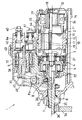
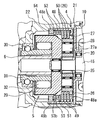
図1はスタータ1の全体断面図、図2は衝撃吸収装置4とその周辺構造を示す拡大断面図である。
The best mode for carrying out the present invention will be described in detail with reference to the following examples.
[Example 1]
FIG. 1 is an overall sectional view of the starter 1, and FIG. 2 is an enlarged sectional view showing an impact absorbing device 4 and its peripheral structure.
本実施例のスタータ1は、図1に示す様に、回転力を発生するモータ2と、このモータ2の回転を減速する減速機3と、エンジン始動時に生じる衝撃力を吸収する衝撃吸収装置4と、減速機3にクラッチ5を介して連結される出力軸6と、この出力軸6に支持されるピニオンギヤ7と、モータ2の通電回路(モータ回路と呼ぶ)に設けられるメイン接点(後述する)を開閉すると共に、シフトレバー8を介して出力軸6を軸方向に移動させる働きを有する電磁スイッチ9等より構成される。なお、図1に示す出力軸6及び電磁スイッチ9の中心線より上側は、スタータ1の停止状態を表し、中心線より下側は、スタータ1の作動状態を表している。
As shown in FIG. 1, the starter 1 of this embodiment includes a motor 2 that generates a rotational force, a
モータ2は、磁気回路を形成する円筒状のヨーク10と、このヨーク10の内周に配置される複数の界磁コイル11と、整流子12を具備する電機子13と、電機子13の回転によって整流子12の表面上を摺接するブラシ14等より構成される周知の整流子型直流電動機である。なお、界磁コイル11に代えて永久磁石を使用することもできる。
The motor 2 includes a
電機子13は、電機子軸15の外周に圧入状態でセレーション嵌合する電機子鉄心16と、この電機子鉄心16に巻線される電機子コイル17とを有し、この電機子コイル17が整流子12を構成する個々のセグメントに接続されている。電機子軸15は、整流子12より後方(図示右方向)へ突き出る後端部が軸受18を介してエンドフレーム19に支持され、電機子鉄心16より前方へ突き出る前端側が軸受20を介してセンタプレート21に支持されている(図1参照)。
The
センタプレート21は、ブラシ粉等の異物が減速機3側へ飛散しない様に、電機子軸15と直交して電機子13と減速機3との間に配置され、外周部がセンタケース22とヨーク10との間に挟持されている。
The
センタケース22は、スタータ1の前方を覆うフロントハウジング23とヨーク10との間に配置されて、クラッチ5と減速機3の外周を覆っている。
このセンタケース22とヨーク10、及びエンドフレーム19は、複数本のスルーボルト24(図1参照)をフロントハウジング23に締め付けて固定されている。
The
The
減速機3は、電機子軸15と同軸上で減速できる遊星歯車減速機であり、電機子13の反整流子側に構成されている。この減速機3は、図1に示す様に、センタプレート21より突き出る電機子軸15の端部に設けられる太陽ギヤ25と、この太陽ギヤ25と同心に配置されると共に、衝撃吸収装置4を介して回転規制されるインターナルギヤ26と、両ギヤ25、26に噛み合う複数の遊星ギヤ27とで構成され、この遊星ギヤ27の公転運動がクラッチ5を介して出力軸6に伝達される。遊星ギヤ27は、軸受28(例えばニードルベアリング)を介して遊星ピン27aに回転自在に支持され、その遊星ピン27aが、以下に説明するクラッチアウタ29に圧入等により固定されている。
The
クラッチ5は、図1に示す様に、減速機3と出力軸6との間に設けられ、減速機3を介してモータ2の駆動トルクが伝達されるクラッチアウタ29と、ベアリング30を介してセンタケース22に回転自在に支持されたインナチューブ31と、クラッチアウタ29の内周に形成されたカム室に配置されて、クラッチアウタ29とインナチューブ31との間でトルクの伝達を断続するローラ32等より構成される。このクラッチ5は、モータ2の駆動トルクを出力軸6に伝達すると共に、出力軸6からモータ2側へのトルク伝達を遮断する一方向クラッチとして構成されている。
As shown in FIG. 1, the
出力軸6は、電機子軸15と同軸線上に配置されると共に、一端側が軸受33を介してフロントハウジング23に回転自在及び摺動自在に支持され、他端側がインナチューブ31の内周に挿入されてヘリカルスプライン結合されている。
The
ピニオンギヤ7は、エンジン始動時にエンジンのリングギヤ34(図1参照)に噛み合い、モータ2の駆動トルクをリングギヤ34に伝達する働きを有する。このピニオンギヤ7は、軸受33より前方(図1の左方向)へ突き出る出力軸6の先端部にセレーション嵌合すると共に、ピニオンギヤ7の内周に配設されたピニオンスプリング35に付勢され、出力軸6の先端部に取り付けられたストッパ36に当接して位置決めされている。
The pinion gear 7 meshes with the ring gear 34 (see FIG. 1) of the engine when the engine is started, and has a function of transmitting the driving torque of the motor 2 to the
電磁スイッチ9は、バッテリから通電されて電磁石を形成する電磁コイル37と、この電磁コイル37の内周を軸方向に可動するプランジャ38とを有し、電磁コイル37への通電によって電磁石が形成されると、その電磁石にプランジャ38が吸引されて、図1に示す右方向へ移動することにより、プランジャ38の動きに連動してモータ回路のメイン接点を閉操作する。また、電磁コイル37への通電が停止して電磁石の吸引力が消滅すると、リターンスプリング39の反力を受けてプランジャ38が押し戻されることにより、メイン接点を開操作する。
The
メイン接点は、2本の外部端子40、41を介してモータ回路に接続される一組の固定接点42と、プランジャ38と一体に可動して一組の固定接点42間を断続する可動接点43とで形成され、この可動接点43を介して一組の固定接点42間が導通することでメイン接点が閉状態となり、一組の固定接点42間の導通が遮断されることでメイン接点が開状態となる。
The main contact includes a set of fixed
2本の外部端子40、41は、バッテリケーブル(図示せず)を介して車載バッテリに接続されるB端子40と、モータ2から取り出されたターミナル44が接続されるM端子41であり、それぞれ電磁スイッチ9の樹脂カバー9aに固定されている。なお、ターミナル44は、ヨーク10とエンドフレーム19との間に挟持されたグロメット45に保持されて、反M端子側の端部が界磁コイル11に接続されている。
The two
シフトレバー8は、揺動自在に支持されるレバー支点部8aを有し、このレバー支点部8aより一端側のレバー端部が電磁スイッチ9に設けられるシフト用ロッド46に連結され、レバー支点部8aより他端側のレバー端部が出力軸6に係合して、プランジャ38の動きを出力軸6に伝達する。
The
シフト用ロッド46は、電磁スイッチ9のプランジャ38にドライブスプリング47と共に組み付けられ、そのドライブスプリング47を介してプランジャ38の動きをシフトレバー8に伝達する働きを有する。
The
次に、本発明に係る衝撃吸収装置4について詳述する。 Next, the impact absorbing device 4 according to the present invention will be described in detail.
衝撃吸収装置4は、例えば、ピニオンギヤ7がリングギヤ34に噛み合う時に発生する衝撃トルクを低減する働きを有し、図2に示す様に、円筒状のケース48、固定ディスク49、回転ディスク50、押圧板51、皿ばね52(本発明の付勢部材)、ワッシャ53(本発明の板状部材)、及びナット54(本発明の固定部材)等より構成される。
The impact absorbing device 4 has a function of reducing impact torque generated when the pinion gear 7 meshes with the
ケース48は、センタケース22の内部に挿入されて回転不能に固定されている。このケース48には、図2に示す右端から内径側へ折り曲げられた環状の底壁部48aが設けられている。底壁部48aの内径は、減速機3の遊星ギヤ27と干渉しない大きさを有している。また、ケース48の内周には、図3に示す様に、固定ディスク49の回転を規制するための凹部48bが複数箇所形成されている。さらに、ケース48の開口部側(反底壁部側)内周には、ナット54を螺着するための雌ねじ部48cが形成されている。
The
固定ディスク49と回転ディスク50は、一枚ずつ交互に重ね合わされることで積層体を成し、且つ、その積層体の両外側は固定ディスク49となるように配置して、ケース48の内周に収納される(図2参照)。
The fixed
固定ディスク49は、図4に示す様に、金属板(例えばりん青銅)をプレス成形してリング形状に設けられ、表面に多数のディンプル49aが形成されている。この固定ディスク49は、外周部に外径方向へ突き出る凸部49bが複数形成され、この凸部49bが、ケース48の内周に設けられた凹部48bに係合して、ケース48に対し回転不能に支持されている(図3参照)。なお、固定ディスク49の内径は、減速機3の遊星ギヤ27と干渉しない大きさを有している。
As shown in FIG. 4, the fixed
回転ディスク50は、図5に示す様に、金属板(例えば銅材)をプレス成形してリング状に設けられ、表面に多数のディンプル50aが形成されている。この回転ディスク50は、ケース48の内周径より僅かに小さい外径を有し、固定ディスク49に対し相対回転可能に配置されている。この回転ディスク50は、図5に示す様に、リング形状の内周全周にインターナルギヤ26を形成する複数の歯が設けられ、これらの歯に減速機3の遊星ギヤ27が噛み合わされている(図2参照)。つまり、回転ディスク50は、減速機3のインターナルギヤ26と一体に設けられている。
As shown in FIG. 5, the
なお、固定ディスク49と回転ディスク50の表面には、潤滑剤であるグリースが塗布されている。
Note that grease, which is a lubricant, is applied to the surfaces of the fixed
押圧板51は、固定ディスク49と同様にリング形状に設けられ、固定ディスク49と回転ディスク50とを積層したディスク積層体の反ケース底面側に配置される。
The
皿ばね52は、固定ディスク49と回転ディスク50とを重ね合わせた積層体に荷重を加えて、固定ディスク49と回転ディスク50との間に摩擦力を発生させている。なお、図2では、ワッシャ53を介して皿ばね52を二段に配置しているが、皿ばね52を一段にしても良い。
The
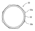
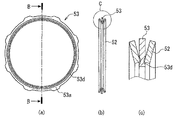
ワッシャ53は、図2に示す様に、2枚の皿ばね52の弾性変形が互いに干渉しないように、2枚の皿ばねの間に介在するように配置されている。即ち、ワッシャ53は皿ばね52に隣接して配置されており、皿ばね52の内周部と当接している。固定ディスク49と同様に、ワッシャ53は、外周部に外径方向へ突き出る凸部53aが複数形成され(図6参照)、この凸部がケース48の内周に設けられた凹部48bに係合することで回転不能に支持されている。
As shown in FIG. 2, the
複数ある凸部53aのうち、いくつかの凸部の先端はプレス成形により折り曲げられ、軸方向に突出する突出部53bが形成されている(図6参照)。この突出部53bは、皿ばね52の外周部を保持することで、ワッシャ53の径方向位置を規制している(図7参照)。また、この突出部53bは、ワッシャ53の外周から突き出すように形成されているため、ケース48の内周に設けられた凹部48bに係合し、ワッシャ53を回転不能に支持している。
Among the plurality of
ナット54は、図8に示す様に、ケース48の雌ねじ部48cに螺着され、固定ディスク49と回転ディスク50との間に規定の滑りトルクが得られる様に、皿ばね52が積層体を押圧する初期荷重を調節している。
As shown in FIG. 8, the
次に、スタータ1の作動を説明する。 Next, the operation of the starter 1 will be described.
始動スイッチ(図示せず)の閉操作により、電磁スイッチ9の電磁コイル37に通電されてプランジャ38が吸引されると、そのプランジャ38の動きがシフトレバー8を介して出力軸6に伝達される。その結果、出力軸6は、インナチューブ31に対してヘリカルスプラインの作用で回転しながら反モータ方向(図1の左方向)へ移動し、ピニオンギヤ7の端面がリングギヤ34の端面に当接した後、ピニオンスプリング35を押し縮めた状態で一旦停止する。
When the
その後、ドライブスプリング47に反力を蓄えながら、プランジャ38が更に移動してメイン接点を閉じると、バッテリからモータ2に給電されて電機子13に回転力が発生し、その電機子13の回転が減速機3で減速された後、クラッチ5を介して出力軸6に伝達される。これにより、出力軸6が強制的に回されるため、ピニオンギヤ7がリングギヤ34に噛み合い可能な位置まで回転した時点で、ドライブスプリング47に蓄えられた反力によりピニオンギヤ7がリングギヤ34の歯の間に飛び出す。その結果、ピニオンギヤ7がリングギヤ34に噛み合って、減速機3で増幅されたモータ2の駆動トルクがピニオンギヤ7からリングギヤ34に伝達されることにより、エンジンをクランキングする。
After that, when the
上記のクランキング時には、ピニオンギヤ7がリングギヤ34に噛み合ってリングギヤ34を駆動する際に衝撃力が発生する。この衝撃力は、ピニオンギヤ7から出力軸6→インナチューブ31→ローラ32→クラッチアウタ29→遊星ピン27a→遊星ギヤ27→インターナルギヤ26へと伝達される。この時、インターナルギヤ26に伝わる衝撃力が、回転ディスク50の滑りトルクを超えると、回転ディスク50が固定ディスク49との間に生じる摩擦力に抗して滑る(回転する)ことにより、衝撃力が低減される。
During the cranking, an impact force is generated when the pinion gear 7 is engaged with the
エンジン始動後、始動スイッチの開操作により、電磁コイル37への通電が停止して電磁石の吸引力が消滅すると、リターンスプリング39の反力でプランジャ38が押し戻されるため、メイン接点が開いてバッテリからモータ2への給電が停止されることにより、電機子13の回転が次第に減速して停止する。
After the engine is started, when the start switch is opened, when the energization of the
一方、プランジャ38が押し戻されると、エンジン始動時とは反対方向にシフトレバー8が揺動して、出力軸6が後退する。
(実施例1の効果)
上記スタータ1において、衝撃吸収装置4に使用される皿ばね52の径方向位置は規制される。このため、皿ばね52の外周部がケース48内周に形成された雌ねじ部48cに引っかかることを防止できる。よって、ナット54の締め付けによる荷重は、雌ねじ部へ集中することなく、皿ばね52を介して固定ディスク49と回転ディスク50の積層体へ作用する。この積層体を押圧する荷重によって、固定ディスクと回転ディスクとの間の所望の摩擦力が確保され、インターナルギヤ26の滑り開始トルク値を適正に維持する効果がある。これにより、エンジンのより確実な始動が行え、且つ、遊星歯車減速装置に加わる衝撃を吸収することができる。
On the other hand, when the
(Effect of Example 1)
In the starter 1, the radial position of the
また、ワッシャ53が回転不能に支持されることにより、ナット54の締め付けによるワッシャ53の動きを抑制でき、ワッシャ53の押圧荷重を安定化させることができる。このため、インターナルギヤの滑り開始トルク値を適正に設定できる。
Further, since the
更に、皿ばね52の径方向位置を規制する手段として、本来皿ばね52同士の弾性変形が互いに干渉しないように設けたワッシャ53を利用し、これに形成した突出部53bを用いるため、スタータ1の部品点数を増加する必要がない。
[実施例2]
上記実施例1の衝撃吸収装置4においては、ワッシャ53に隣接配置されるナット54側の皿ばね52について、径方向位置を規制する例を示した。
Further, as a means for regulating the radial position of the
[Example 2]
In the impact absorbing device 4 of the first embodiment, the example in which the radial position of the
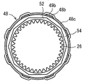
これに対し本実施例2では、実施例1におけるワッシャ53の外周部に設けられた複数の凸部53a(図7参照)を、突出部53bとは反対の方向(インターナルギヤ26方向)に曲折させた突出部53cを形成する。これにより、ワッシャ53の軸方向両側に隣接する皿ばね52は、同時に径方向位置を規制される(図9参照)。このとき、図10に示す様に、複数の突出部53bと複数の突出部53cは周方向に交互に設けられている。
On the other hand, in the second embodiment, the plurality of
また本実施例においても、突出部53b、突出部53cは共にケース48内周に設けられた凹部と係合するように設計されているため、ワッシャ53は回転不能に支持されている。
(実施例2の効果)
本実施例2では、ワッシャ53の軸方向両側に隣接する皿ばね52の径方向位置を同時に規制することで、皿ばね52の外周部がケース48内周の雌ねじ部48cに引っかかることを防止できる。また、ワッシャ53の外周に設けられた複数の突出部53bと複数の突出部53cが周方向に交互に設けられることで、突出部53b、53cがワッシャ53の外周部に作用する荷重を均等にすることができ、ワッシャ53はケース48の中心軸に対し確実に芯出しされる。これによって、両側の皿ばね52の内周部がワッシャ53に当接する面が、ワッシャ53の両面で略同じ(ずれ幅0.0〜0.5mm)位置になるため、ナット54の締め付けによる荷重は、偏りが防止され、効率よく回転ディスクと固定ディスクの積層体へ伝達される。
Also in this embodiment, since both the protruding
(Effect of Example 2)
In the second embodiment, by restricting the radial positions of the disc springs 52 adjacent to both sides in the axial direction of the
また本実施例2においても、ワッシャ53は回転不能に支持されていることで、実施例1と同様の効果が得られる。
[実施例3]
上記実施例1または2の衝撃吸収装置4においては、皿ばね52の径方向位置を規制する手段として、皿ばね52に隣接配置されるワッシャ53に設けられた突出部53b、53cを用いる例を示した。
Also in the second embodiment, since the
[Example 3]
In the impact absorbing device 4 of the first or second embodiment, as an example of using the
本実施例3では、皿ばね52の径方向位置を規制する手段として、皿ばね52に隣接配置されるワッシャ53の両面にそれぞれ設けられた円周状の凹部53dを用いる。この凹部53dは、図11に示す様に、例えばプレス加工などによりワッシャ53の表面上に円周状に形成される。皿ばね52は、その軸方向端部となる内周部がこの凹部53dに係合することで径方向位置を規制される。
(実施例3の効果)
本実施例3では、皿ばね52がワッシャ53に設けられた凹部53dにより径方向位置を規制される。これによって、皿ばね52の外周部がケース48の内周に形成された雌ねじ部へ引っかかることを防止でき、実施例1または2と同様の効果が得られる。
[実施例4]
上記実施例3の衝撃吸収装置においては、皿ばね52の径方向位置を規制する手段として、皿ばね52に隣接配置されるワッシャ53に設けられた円周状の凹部53dを用いる例を示した。
In the third embodiment, as a means for regulating the radial position of the
(Effect of Example 3)
In the third embodiment, the
[Example 4]
In the impact absorbing device of the third embodiment, an example in which a
本実施例4では、皿ばね52の径方向位置を規制する手段として、皿ばね52に隣接配置されるワッシャ53の両面に設けられた円周状の凹部53eを用いる。この凹部53eは、図12に示す様に、例えば切削加工などによりワッシャ53の表面の一部を円周状に削り取ることで形成される。皿ばね52は、その軸方向端部となる内周部がこの凹部53eに係合することで径方向位置を規制される。
(実施例4の効果)
本実施例3では、皿ばね52がワッシャ53に設けられた凹部53eにより径方向位置を規制される。これによって、皿ばね52の外周部がケース48の内周に形成された雌ねじ部へ引っかかることを防止でき、実施例3と同様の効果が得られる。
(変形例)
実施例1と2の衝撃吸収装置4において、皿ばね52の径方向位置を規制する手段は、隣接配置されるワッシャ53に設ける他に、例えばナット54や押圧板51などに設けてもよい。
In the fourth embodiment, as a means for restricting the radial position of the
(Effect of Example 4)
In the third embodiment, the
(Modification)
In the impact absorbing device 4 of the first and second embodiments, the means for regulating the radial position of the
実施例3と4の衝撃吸収装置4において、皿ばね52の外周部がワッシャ53に当接するように配置し、この外周部がワッシャ53の凹部53d、53eに係合するような構成にしてもよい。また、ワッシャ53の凹部53d、53eは円周状に形成されなくとも、数箇所に凹部を設け、それに係合するような爪を皿ばね52に形成するようにしてもよい。
In the impact absorbing device 4 according to the third and fourth embodiments, the outer periphery of the
実施例1〜4の何れかの衝撃吸収装置4において、皿ばね52の代わりにウェーブスプリングなど、他の弾性体を用いてもよい。
In the impact absorbing device 4 of any one of the first to fourth embodiments, another elastic body such as a wave spring may be used instead of the
1 スタータ
2 モータ
3 減速器(遊星歯車減速装置)
4 衝撃吸収装置
6 出力軸
7 ピニオンギヤ
26 インターナルギヤ
48 ケース
48b ケース内周の凹部
48c ケース内周の雌ねじ部
49 固定ディスク
50 回転ディスク
52 皿ばね(付勢部材)
53 ワッシャ(板状部材)
53b ワッシャに設けられたナット方向の突出部(位置規制手段)
53c ワッシャに設けられたインターナルギヤ方向の突出部(位置規制手段)
53d ワッシャに設けられた凹部(位置規制手段)
53e ワッシャに設けられた凹部(位置規制手段)
54 ナット(固定部材)
1 starter 2
4
53 Washer (plate-like member)
53b Protruding portion in the nut direction provided on the washer (position restricting means)
53c Protruding portion in the internal gear direction provided on the washer (position restricting means)
53d Recessed portion (position restricting means) provided in the washer
53e Concave portion provided on the washer (position restricting means)
54 Nut (fixing member)
Claims (12)
軸上にピニオンギヤを有する出力軸と、
前記モータの回転を減速して前記出力軸に伝達する遊星歯車減速装置と、
この遊星歯車減速装置に使用されるインターナルギヤと一体に設けられた回転ディスクと、この回転ディスクの板厚方向に隣接して回転不能に配置される固定ディスクと、前記回転ディスクと前記固定ディスクを内部に収容すると共にその開口端側内周に雌ねじ部を有するケースと、前記雌ねじ部の内径側に配置されて前記回転ディスクと前記固定ディスクに荷重を与える付勢部材と、前記雌ねじ部に螺合して前記付勢部材の押圧量を調節する固定部材とを有し、前記回転ディスクと前記固定ディスクとが所定の押圧力を受けて摩擦接触すると共に、前記インターナルギヤを介して前記回転ディスクに所定値以上の負荷トルクが加わった時に、前記回転ディスクが摩擦力に抗して回転することにより、前記遊星歯車減速装置に加わる衝撃を吸収する衝撃吸収装置とを備えるスタータであって、
前記雌ねじ部の最内径より内周領域内に前記付勢部材の最外径部を配置するように、前記付勢部材の径方向位置を規制する位置規制手段を有することを特徴とするスタータ。 A motor that generates rotational force;
An output shaft having a pinion gear on the shaft;
A planetary gear reduction device that decelerates the rotation of the motor and transmits it to the output shaft;
A rotating disk provided integrally with an internal gear used in the planetary gear speed reducer, a fixed disk disposed non-rotatably adjacent to the thickness direction of the rotating disk, the rotating disk, and the fixed disk In the inner periphery of the opening end side, an urging member disposed on the inner diameter side of the female screw portion for applying a load to the rotating disk and the fixed disk, and the female screw portion A fixed member that adjusts the pressing amount of the urging member by screwing, and the rotating disk and the fixed disk receive a predetermined pressing force and are in frictional contact with each other via the internal gear. When a load torque of a predetermined value or more is applied to the rotating disk, the rotating disk rotates against the frictional force to absorb the impact applied to the planetary gear reduction device. A starter and a shock absorbing device for,
A starter characterized by having a position restricting means for restricting a radial position of the urging member so that an outermost diameter portion of the urging member is disposed in an inner peripheral area from an innermost diameter of the female screw portion.
前記位置規制手段は、前記付勢部材の軸方向に隣接して配置される隣接部材に一体に設けられていることを特徴とするスタータ。 The starter according to claim 1,
The starter characterized in that the position restricting means is provided integrally with an adjacent member disposed adjacent to the urging member in the axial direction.
前記位置規制手段は、前記付勢部材の外周部を保持するように、前記隣接部材から軸方向に突出する突出部であることを特徴とするスタータ。 The starter according to claim 2,
The starter characterized in that the position restricting means is a protruding portion that protrudes in the axial direction from the adjacent member so as to hold the outer peripheral portion of the biasing member.
前記隣接部材は板状部材であって、この板状部材の外周側を曲折することで前記突出部を形成したことを特徴とするスタータ。 The starter according to claim 3,
The adjacent member is a plate-like member, and the protrusion is formed by bending the outer peripheral side of the plate-like member.
前記板状部材は、その軸方向両側に配置されている前記付勢部材の径方向位置を規制する前記突出部を設けたことを特徴とするスタータ。 The starter according to claim 4,
The said plate-shaped member provided the said protrusion part which controls the radial direction position of the said urging | biasing member arrange | positioned at the axial direction both sides, The starter characterized by the above-mentioned.
前記板状部材は、軸方向一端側に設けた複数の前記突出部と軸方向他端側に設けた複数の前記突出部とが、周方向に交互に設けられていることを特徴とするスタータ。 The starter according to claim 5, wherein
The plate-like member has a plurality of the protruding portions provided on one end side in the axial direction and a plurality of the protruding portions provided on the other end side in the axial direction alternately provided in the circumferential direction. .
前記隣接部材は板状部材であって、前記位置規制手段は前記付勢部材の軸方向端部を保持する凹部を有することを特徴とするスタータ。 The starter according to claim 2,
The adjacent member is a plate-like member, and the position restricting means has a recess for holding an end portion in the axial direction of the biasing member.
前記板状部材は、その軸方向両側に配置されている前記付勢部材の径方向位置を規制する前記凹部を設けたことを特徴とするスタータ。 The starter according to claim 7,
The said plate-shaped member provided the said recessed part which controls the radial direction position of the said urging | biasing member arrange | positioned at the axial direction both sides.
前記付勢部材は、前記ケースの中心軸に対し芯出しされるように径方向位置を規制されることを特徴とするスタータ。 The starter according to claim 6 or 8,
The starter characterized in that the urging member is regulated in a radial direction so as to be centered with respect to a central axis of the case.
前記板状部材は、これの外周部に外径方向に設けられた凸部が前記ケース内周に設けられた凹部に係合することで、回転不能に支持されることを特徴とするスタータ。 A starter according to any one of claims 4 to 9,
The plate-like member is supported in a non-rotatable manner by engaging a convex portion provided in an outer diameter direction on an outer peripheral portion thereof with a concave portion provided in the inner periphery of the case.
前記板状部材は、複数の前記付勢部材の間に介在するワッシャであることを特徴とするスタータ。 The starter according to any one of claims 4 to 10,
The plate-like member is a washer interposed between a plurality of the biasing members.
前記付勢部材は、皿ばねであることを特徴とするスタータ。 The starter according to any one of claims 1 to 11,
The starter characterized in that the biasing member is a disc spring.
Priority Applications (2)
| Application Number | Priority Date | Filing Date | Title |
|---|---|---|---|
| JP2008274123A JP5176868B2 (en) | 2008-10-24 | 2008-10-24 | Starter |
| US12/588,584 US8567364B2 (en) | 2008-10-24 | 2009-10-20 | Starter equipped with planetary speed reducer and shock absorber |
Applications Claiming Priority (1)
| Application Number | Priority Date | Filing Date | Title |
|---|---|---|---|
| JP2008274123A JP5176868B2 (en) | 2008-10-24 | 2008-10-24 | Starter |
Publications (2)
| Publication Number | Publication Date |
|---|---|
| JP2010101260A true JP2010101260A (en) | 2010-05-06 |
| JP5176868B2 JP5176868B2 (en) | 2013-04-03 |
Family
ID=42116270
Family Applications (1)
| Application Number | Title | Priority Date | Filing Date |
|---|---|---|---|
| JP2008274123A Expired - Fee Related JP5176868B2 (en) | 2008-10-24 | 2008-10-24 | Starter |
Country Status (2)
| Country | Link |
|---|---|
| US (1) | US8567364B2 (en) |
| JP (1) | JP5176868B2 (en) |
Families Citing this family (2)
| Publication number | Priority date | Publication date | Assignee | Title |
|---|---|---|---|---|
| DE102012216143B4 (en) * | 2012-09-12 | 2021-03-18 | Seg Automotive Germany Gmbh | Starting device for an internal combustion engine |
| EP2870905B1 (en) | 2013-11-11 | 2019-01-02 | NELA razvojni center d.o.o. Podruznica OTOKI | Vacuum cleaner noise and vibration reduction system |
Citations (5)
| Publication number | Priority date | Publication date | Assignee | Title |
|---|---|---|---|---|
| JPS5996459U (en) * | 1982-12-21 | 1984-06-30 | 富士電機株式会社 | Gear slip mechanism |
| JPH01316558A (en) * | 1988-06-17 | 1989-12-21 | Mitsubishi Electric Corp | Device for limiting transmission of torque |
| JP2004232785A (en) * | 2003-01-31 | 2004-08-19 | Mitsuba Corp | Torque limiter |
| JP2008095322A (en) * | 2006-10-10 | 2008-04-24 | Sankyo Tateyama Aluminium Inc | Torque limiter for electric opening/closing equipment |
| JP2008223572A (en) * | 2007-03-12 | 2008-09-25 | Denso Corp | Starter |
Family Cites Families (8)
| Publication number | Priority date | Publication date | Assignee | Title |
|---|---|---|---|---|
| US2679170A (en) * | 1952-04-16 | 1954-05-25 | Jack & Heintz Inc | Torque limiting device |
| US5905309A (en) * | 1996-02-15 | 1999-05-18 | Denso Corporation | Starter with shock absorbing device |
| JP3603508B2 (en) * | 1996-02-15 | 2004-12-22 | 株式会社デンソー | Starter |
| JP2004060520A (en) * | 2002-07-29 | 2004-02-26 | Denso Corp | Starter |
| JP4135524B2 (en) * | 2003-02-19 | 2008-08-20 | 株式会社デンソー | Starter |
| JP4174820B2 (en) * | 2003-03-11 | 2008-11-05 | 株式会社デンソー | Starter |
| JP4561758B2 (en) | 2007-02-20 | 2010-10-13 | 株式会社デンソー | Starter |
| US20080196544A1 (en) | 2007-02-20 | 2008-08-21 | Denso Corporation | Starter having excessive-torque-absorbing device |
-
2008
- 2008-10-24 JP JP2008274123A patent/JP5176868B2/en not_active Expired - Fee Related
-
2009
- 2009-10-20 US US12/588,584 patent/US8567364B2/en active Active
Patent Citations (5)
| Publication number | Priority date | Publication date | Assignee | Title |
|---|---|---|---|---|
| JPS5996459U (en) * | 1982-12-21 | 1984-06-30 | 富士電機株式会社 | Gear slip mechanism |
| JPH01316558A (en) * | 1988-06-17 | 1989-12-21 | Mitsubishi Electric Corp | Device for limiting transmission of torque |
| JP2004232785A (en) * | 2003-01-31 | 2004-08-19 | Mitsuba Corp | Torque limiter |
| JP2008095322A (en) * | 2006-10-10 | 2008-04-24 | Sankyo Tateyama Aluminium Inc | Torque limiter for electric opening/closing equipment |
| JP2008223572A (en) * | 2007-03-12 | 2008-09-25 | Denso Corp | Starter |
Also Published As
| Publication number | Publication date |
|---|---|
| US20100101524A1 (en) | 2010-04-29 |
| US8567364B2 (en) | 2013-10-29 |
| JP5176868B2 (en) | 2013-04-03 |
Similar Documents
| Publication | Publication Date | Title |
|---|---|---|
| JP4552924B2 (en) | Starter | |
| JP4174820B2 (en) | Starter | |
| JP2010255590A (en) | Starter | |
| JP2010242556A (en) | Starter | |
| JPWO2006043580A1 (en) | Starter motor with idle gear | |
| JP4957530B2 (en) | Starter | |
| JP2005113816A (en) | Starter | |
| JP2006336491A (en) | Starter | |
| JP4831043B2 (en) | Starter | |
| JP5176868B2 (en) | Starter | |
| JP5765974B2 (en) | Starter | |
| JP5115218B2 (en) | Starter | |
| JP2004060520A (en) | Starter | |
| JP2007077810A (en) | Starter | |
| JP4858393B2 (en) | Shock absorber | |
| JP4544254B2 (en) | Starter | |
| JPS6347654Y2 (en) | ||
| JP4561758B2 (en) | Starter | |
| JP4872907B2 (en) | Starter | |
| JP4816596B2 (en) | Starter | |
| JP2008082252A (en) | Starter motor with idle gear | |
| JP4450216B2 (en) | Starter | |
| JP2007270819A (en) | Starter motor with idle gear | |
| JP5580221B2 (en) | Starter | |
| JP2008255949A (en) | Starter |
Legal Events
| Date | Code | Title | Description |
|---|---|---|---|
| A621 | Written request for application examination |
Free format text: JAPANESE INTERMEDIATE CODE: A621 Effective date: 20110607 |
|
| A977 | Report on retrieval |
Free format text: JAPANESE INTERMEDIATE CODE: A971007 Effective date: 20120920 |
|
| A131 | Notification of reasons for refusal |
Free format text: JAPANESE INTERMEDIATE CODE: A131 Effective date: 20120925 |
|
| A521 | Written amendment |
Free format text: JAPANESE INTERMEDIATE CODE: A523 Effective date: 20121122 |
|
| TRDD | Decision of grant or rejection written | ||
| A01 | Written decision to grant a patent or to grant a registration (utility model) |
Free format text: JAPANESE INTERMEDIATE CODE: A01 Effective date: 20121211 |
|
| A61 | First payment of annual fees (during grant procedure) |
Free format text: JAPANESE INTERMEDIATE CODE: A61 Effective date: 20121224 |
|
| R151 | Written notification of patent or utility model registration |
Ref document number: 5176868 Country of ref document: JP Free format text: JAPANESE INTERMEDIATE CODE: R151 |
|
| FPAY | Renewal fee payment (event date is renewal date of database) |
Free format text: PAYMENT UNTIL: 20160118 Year of fee payment: 3 |
|
| R250 | Receipt of annual fees |
Free format text: JAPANESE INTERMEDIATE CODE: R250 |
|
| R250 | Receipt of annual fees |
Free format text: JAPANESE INTERMEDIATE CODE: R250 |
|
| R250 | Receipt of annual fees |
Free format text: JAPANESE INTERMEDIATE CODE: R250 |
|
| R250 | Receipt of annual fees |
Free format text: JAPANESE INTERMEDIATE CODE: R250 |
|
| R250 | Receipt of annual fees |
Free format text: JAPANESE INTERMEDIATE CODE: R250 |
|
| LAPS | Cancellation because of no payment of annual fees |