JP2010101124A - Lock device for door - Google Patents

Lock device for door Download PDF

Info

Publication number
JP2010101124A
JP2010101124A JP2008275469A JP2008275469A JP2010101124A JP 2010101124 A JP2010101124 A JP 2010101124A JP 2008275469 A JP2008275469 A JP 2008275469A JP 2008275469 A JP2008275469 A JP 2008275469A JP 2010101124 A JP2010101124 A JP 2010101124A
Authority
JP
Japan
Prior art keywords
door
latch
authentication
locking
unit
Prior art date
Legal status (The legal status is an assumption and is not a legal conclusion. Google has not performed a legal analysis and makes no representation as to the accuracy of the status listed.)
Granted
Application number
JP2008275469A
Other languages
Japanese (ja)
Other versions
JP5634671B2 (en
Inventor
Ayaichi Takami
綾一 高見
Kiyofumi Sato
清文 佐藤
Current Assignee (The listed assignees may be inaccurate. Google has not performed a legal analysis and makes no representation or warranty as to the accuracy of the list.)
Alpha Corp
Original Assignee
Alpha Corp
Priority date (The priority date is an assumption and is not a legal conclusion. Google has not performed a legal analysis and makes no representation as to the accuracy of the date listed.)
Filing date
Publication date
Application filed by Alpha Corp filed Critical Alpha Corp
Priority to JP2008275469A priority Critical patent/JP5634671B2/en
Publication of JP2010101124A publication Critical patent/JP2010101124A/en
Application granted granted Critical
Publication of JP5634671B2 publication Critical patent/JP5634671B2/en
Active legal-status Critical Current
Anticipated expiration legal-status Critical

Links

Images

Abstract

<P>PROBLEM TO BE SOLVED: To improve use convenience in a lock device for a door by increasing the speed of unlocking operation. <P>SOLUTION: The lock device includes an electric lock part 4 including a dead bolt 3, the bolt being driven between locking and unlocking positions with a dead bolt driving actuator 1 and regulating the opening operation of a door 2 in the locking position; a read-ahead part 6 which outputs an answer request signal to a portable device 5 carried by a user, the portable device outputting authentication ID signal in response to the answer request signal, at predetermined time intervals, and stores an authentication result for the received ID signal; an electric lock control part 7 which unlock-drives the electric lock part 4 on condition that authentication establishment information is stored in the look-ahead part 6, maintains the unlock state until the information stored in the read-ahead part is changed to authentication non-establishment, and then performs shifting to the lock state; and a latch part 10 which includes a latch 9, the latch being engagingly locked to a door frame 8 by projecting from the door 2, and releasing the locking state with the door frame 8 in a recessed state to the door 2. <P>COPYRIGHT: (C)2010,JPO&INPIT

Description

本発明は、扉用錠装置に関するものである。   The present invention relates to a door locking device.

アクチュエータにより施解錠駆動される扉用錠装置としては、特許文献1に記載のものが知られている。この従来例において、扉用錠装置は、扉枠に進退するデッドボルトを備えた電気錠と、ソレノイド等により駆動されるラッチボルトとを有し、デッドボルトとラッチボルトの双方が突出した施錠状態の解錠は、利用者による電気錠への解錠操作と、タッチセンサ等の人体検知センサによる人体検知により行われる。
特開平11-293975号公報
As a door locking device driven and unlocked by an actuator, the one described in Patent Document 1 is known. In this conventional example, the door locking device has an electric lock having a dead bolt that advances and retreats to the door frame, and a latch bolt that is driven by a solenoid or the like, and both the dead bolt and the latch bolt protrude. The unlocking is performed by unlocking the electric lock by the user and detecting the human body by a human body detection sensor such as a touch sensor.
JP-A-11-293975

しかし、上述した従来例において、解錠動作には、利用者の認証、認証成立後のデッドボルトの引き込み駆動、ラッチボルトの解除駆動を行う必要があり、利用者はこれらの動作が完全に完了するまで扉の前で待っていなければならず、使い勝手が悪いという欠点がある。   However, in the above-described conventional example, the unlocking operation requires user authentication, dead bolt pull-in drive after authentication is established, and latch bolt release drive, and the user completes these operations completely. You have to wait in front of the door until you do it, and it has the disadvantage of being unusable.

本発明は、以上の欠点を解消すべくなされたものであって、解錠動作の速度を高めることによって使い勝手を向上させた扉用錠装置の提供を目的とする。   The present invention has been made to eliminate the above-described drawbacks, and an object of the present invention is to provide a door locking device that is improved in usability by increasing the speed of the unlocking operation.

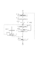
扉用錠装置は電気錠部4に加え、先読み部6と、電気錠制御部7と、ラッチ部10とを有し、同一ケース内に、あるいは扉2周辺に分散配置される。   In addition to the electric lock unit 4, the door locking device includes a pre-reading unit 6, an electric lock control unit 7, and a latch unit 10, and is distributed in the same case or around the door 2.

電気錠部4はデッドボルト駆動用アクチュエータ1により施解錠位置間で駆動されるデッドボルト3を備え、該デッドボルト3が施錠位置にあるとき、扉2から突出して扉枠8に係止し、扉2の開放操作を規制する。   The electric lock unit 4 includes a dead bolt 3 that is driven between the locking and unlocking positions by the dead bolt driving actuator 1. When the dead bolt 3 is in the locking position, the electric locking unit 4 protrudes from the door 2 and is locked to the door frame 8. The opening operation of the door 2 is restricted.

先読み部6は、利用者が所持する携帯器5に対して応答要求信号を所定時間間隔で出力し、応答要求信号に対する携帯器5からのレスポンスを受信する。レスポンスには、携帯器毎に与えられた携帯器固有の認証用ID信号が含まれ、当該認証用ID信号が予め認証成立可能なIDとして登録されたものであるか否かが格納される。先読み部6での認証可否情報は、応答要求信号に対するレスポンスに対応して書き替えられる。また、応答要求信号の送出間隔は、固定したものであっても、あるいは巡回動作により認証可能な携帯器5が検出された場合には、携帯器5が検出されなくなるまで、巡回間隔を短くするように、可変のものであってもよい。   The prefetch unit 6 outputs a response request signal to the portable device 5 possessed by the user at predetermined time intervals, and receives a response from the portable device 5 in response to the response request signal. The response includes a portable device-specific authentication ID signal given to each portable device, and stores whether or not the authentication ID signal is registered in advance as an ID that can be authenticated. The authentication propriety information in the prefetch unit 6 is rewritten corresponding to the response to the response request signal. Further, even if the response request signal transmission interval is fixed, or when the portable device 5 that can be authenticated is detected by the cyclic operation, the cyclic interval is shortened until the portable device 5 is not detected. As such, it may be variable.

電気錠制御部7は、先読み部6が認証成立信号を保持したとき、すなわち認証可能な携帯器5が先読み部6での交信可能範囲に進入してきたときにデッドボルト駆動用アクチュエータ1を駆動し、電気錠部4を解錠状態に遷移させる。解錠状態は、先読み部6における認証成立信号が消失するまで維持され、その後、再びデッドボルト駆動用アクチュエータ1を駆動して電気錠部4を施錠状態に復帰させる。   The electric lock control unit 7 drives the dead bolt driving actuator 1 when the prefetch unit 6 holds the authentication establishment signal, that is, when the authenticable portable device 5 enters the communicable range of the prefetch unit 6. Then, the electric lock unit 4 is changed to the unlocked state. The unlocked state is maintained until the authentication establishment signal in the prefetching unit 6 disappears, and then the dead bolt driving actuator 1 is driven again to return the electric lock unit 4 to the locked state.

認証可能な携帯器5が交信可能範囲に進入したタイミングで電気錠部4を解錠状態にする本発明において、扉2の前で解錠操作を行い、携帯器5に対する認証、デッドボルト3の解錠動作完了を待つ場合に比して、早く扉2の開放操作を行うことができるために、利便性が向上する。   In the present invention in which the electric lock unit 4 is unlocked when the authenticable portable device 5 enters the communicable range, the unlocking operation is performed in front of the door 2 to authenticate the portable device 5 and the dead bolt 3 Compared with the case of waiting for the unlocking operation to be completed, the door 2 can be opened quickly, so the convenience is improved.

また、置き忘れの携帯器5による誤動作の防止のためにレスポンス信号の出力をモーション検出部等による動き検出を条件とする携帯器5を使用する場合、静止した状態で行われることの多い扉2の前での認証動作では、携帯器5がレスポンス信号を出力しない可能性がある。これに対し、携帯器5交信開始時から扉2までの移動は携帯器5の動きを必然的に伴うために、この期間で認証動作を終了させる本発明においては、上述した問題の発生を確実に防止できる。   In addition, in order to prevent a malfunction caused by the misplaced portable device 5, when the portable device 5 is used on the condition that the response signal is output by motion detection by a motion detection unit or the like, the door 2 is often kept stationary. In the previous authentication operation, the portable device 5 may not output a response signal. On the other hand, since the movement from the start of communication of the portable device 5 to the door 2 is necessarily accompanied by the movement of the portable device 5, in the present invention in which the authentication operation is terminated during this period, the occurrence of the above-described problem is ensured. Can be prevented.

さらに、電気錠部4は、先読み部6における認証成立信号が消失することにより自動的に施錠状態に復帰するために、例えば、一旦交信可能エリアに進入した後、入室することなく再び交信可能エリアから退出した場合であっても電気錠部4が解錠状態のまま放置させる不具合が発生しない。認証成立信号の消失は、先読み部6における認証可否信号の書き替え動作時に認証可能携帯器5が交信範囲内に存在しない場合に発生し、上述したように、入室前の待避に加え、入室による交信遮断、あるいは入室後に携帯器5を置くことによるモーション停止等、種々の設定された条件の満足によりもたらされる。   Further, the electric lock unit 4 automatically returns to the locked state when the authentication establishment signal in the pre-reading unit 6 disappears. For example, the electric lock unit 4 once enters the communicable area and then enters the communicable area again without entering the room. Even when the user exits from the terminal, there is no problem that the electric lock unit 4 is left in the unlocked state. The disappearance of the authentication establishment signal occurs when the authenticable portable device 5 does not exist within the communication range during the rewriting operation of the authentication permission / prohibition signal in the prefetch unit 6, and as described above, in addition to evacuation before entering the room, It is brought about by satisfying various set conditions such as communication interruption or motion stoppage by placing the portable device 5 after entering the room.

また、ラッチ部10は、ラッチ9を扉枠8に係止させることにより、電気錠部4におけるデッドボルト3の係止解除によって扉2が風圧等により妄りに開放されることを防止する。   In addition, the latch portion 10 locks the latch 9 to the door frame 8, thereby preventing the door 2 from being unintentionally opened due to wind pressure or the like due to the unlocking of the dead bolt 3 in the electric lock portion 4.

さらに、扉用錠装置には、扉2または扉2近傍に設置され、携帯器5との交信距離に比して短い検出距離内で操作者を検出する操作者検出部11を含めることができる。この場合、ラッチ部10は、
ロック位置においてラッチ9の没入操作を規制し、ロック解除位置においてラッチ9の没入を許容するラッチストッパ12と、
電気錠部4が解錠状態であること、および操作者検出部11における操作者検出を条件としてラッチストッパ12をロック解除位置に駆動するラッチ駆動用アクチュエータ13とを有して構成される。
Furthermore, the door lock device can include an operator detection unit 11 that is installed in the door 2 or in the vicinity of the door 2 and detects an operator within a detection distance shorter than the communication distance with the portable device 5. . In this case, the latch unit 10 is
A latch stopper 12 for restricting the immersing operation of the latch 9 at the locked position and allowing the immersing of the latch 9 at the unlocked position;
The electric lock unit 4 is in an unlocked state, and includes a latch driving actuator 13 that drives the latch stopper 12 to the unlocked position on condition that the operator is detected by the operator detecting unit 11.

以上のように構成すると、ラッチストッパ12の動作を電気錠部4の動作に関連付けることができ、結果、電気錠部4が施錠状態にあるとき、ラッチ9の没入も規制されるために、二重施錠の状態になり、防犯性能が向上する。また、ラッチストッパ12の解除タイミングを、携帯器5との交信距離に比して短い検出距離内で操作者を検出する操作者検出部11での操作者検出により決定することによって、利用者の扉2の直近位置への移動に伴ってラッチ9を没入操作することが可能な状態になっているために、利用者は何等の動作完了を待たされることなく直ぐに開扉操作を行うことができる。   With the configuration as described above, the operation of the latch stopper 12 can be related to the operation of the electric lock portion 4. As a result, when the electric lock portion 4 is in the locked state, the immersion of the latch 9 is also restricted. It becomes the state of heavy locking, and the crime prevention performance improves. Further, by determining the release timing of the latch stopper 12 by the operator detection in the operator detection unit 11 that detects the operator within a detection distance shorter than the communication distance with the portable device 5, Since the latch 9 can be immersed in accordance with the movement of the door 2 to the nearest position, the user can immediately open the door without waiting for any operation to be completed. .

ラッチ9には、扉2からの進退移動のみが許容されるものに加え、扉枠8との当接面が開扉軌跡に直交する係止姿勢と、開扉軌跡に対して斜行し、開扉操作による没入方向の分力が発生する没入可能姿勢との間を回転自在な反転ラッチ9の双方を使用することができる。並進移動のみによって扉枠8との係止が解除されるラッチ9において、ラッチ9の没入操作は、ハンドル、あるいは扉2表面に設置された可動操作部材への操作が必要となるが、反転ラッチ9においては、ラッチストッパ12の解除をラッチ駆動用アクチュエータ13により行うことによって、扉2を押すだけで開扉操作を行うことができる。この結果、扉2に可動操作部材を配置する必要がないために、構造が簡単になる。   In addition to the latch 9 only allowing forward and backward movement from the door 2, the contact surface with the door frame 8 is inclined with respect to the locking posture perpendicular to the opening locus, and the opening locus, It is possible to use both the reversing latches 9 that are rotatable between the immersable posture in which the component force in the immersive direction is generated by the opening operation. In the latch 9 that is unlocked from the door frame 8 only by translational movement, the immersion operation of the latch 9 requires an operation to the handle or the movable operation member installed on the surface of the door 2. 9, the latch stopper 12 is released by the latch drive actuator 13, so that the door can be opened simply by pushing the door 2. As a result, since it is not necessary to arrange a movable operation member on the door 2, the structure is simplified.

上記操作者検出部11には、例えば赤外線近接センサ等により形成されるヒトセンサが使用できるが、ラッチ部10に反転ラッチ9を使用する場合には、扉操作ハンドル14に組み込まれた接触センサ11を使用するのが望ましい。すなわち、反転ラッチを使用する場合、ラッチストッパ解除により扉2は風圧等によっても開放可能な状態となるが、扉操作ハンドル14に組み込まれた接触センサ11を使用すると、扉操作ハンドル14に触れた状態でのラッチストッパ12の解除が保証される。接触センサ11には、通常の押しボタンスイッチに加え、静電容量センサを使用することができる。   For the operator detection unit 11, for example, a human sensor formed by an infrared proximity sensor or the like can be used. However, when the reverse latch 9 is used for the latch unit 10, the contact sensor 11 incorporated in the door operation handle 14 is used. It is desirable to use it. That is, when the reverse latch is used, the door 2 can be opened by wind pressure or the like by releasing the latch stopper, but if the contact sensor 11 incorporated in the door operation handle 14 is used, the door operation handle 14 is touched. The release of the latch stopper 12 in the state is guaranteed. The contact sensor 11 can be a capacitance sensor in addition to a normal push button switch.

本発明によれば、電気錠部への解錠動作は認証可能な携帯器が交信エリア内に進入したことによって開始され、利用者が扉の前に立ったときにはすでにデッドボルトは解錠状態となっているために、解錠動作の速度が早くなり、使い勝手を向上させることができる。   According to the present invention, the unlocking operation to the electric lock part is started when an authenticable portable device enters the communication area, and when the user stands in front of the door, the dead bolt has already been unlocked. Therefore, the speed of the unlocking operation is increased, and usability can be improved.

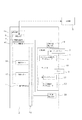
図1に示すように、扉用錠装置は、電気錠部4と、ラッチ部10と、電気錠部4、およびラッチ部10の動作を制御する錠制御部15とを有する。図1には、電気錠部4、ラッチ部10、および錠制御部15を扉2に固定した場合を示すが、錠制御部15は、扉2以外に配置することもできる。   As shown in FIG. 1, the door locking device includes an electric lock unit 4, a latch unit 10, an electric lock unit 4, and a lock control unit 15 that controls the operation of the latch unit 10. Although FIG. 1 shows a case where the electric lock unit 4, the latch unit 10, and the lock control unit 15 are fixed to the door 2, the lock control unit 15 can be arranged other than the door 2.

また、扉2には、扉2の開放操作を行う際の手掛けとなる扉操作ハンドル14と、施解錠操作を行う際の施錠ボタン16、および解錠ボタン17が配置され、扉操作ハンドル14の適宜箇所には、操作者検出部11としての静電容量センサが配置される。   Further, the door 2 is provided with a door operation handle 14 which is a handle when the door 2 is opened, a lock button 16 and an unlock button 17 when performing the unlocking operation. A capacitance sensor as the operator detection unit 11 is disposed at an appropriate place.

電気錠部4は、上記錠制御部15により制御されて施解錠駆動されるデッドボルト駆動用アクチュエータ1と、デッドボルト駆動用アクチュエータ1により扉枠8に向けて施解錠位置間を進退駆動され、扉2から一端が突出する施錠位置において扉枠8に係止して扉2への開放操作を規制するデッドボルト3とを錠ケース18内に固定して形成される。   The electric lock part 4 is driven by the dead bolt drive actuator 1 controlled by the lock control part 15 and driven to unlock and drive, and the dead bolt drive actuator 1 is driven forward and backward between the lock and unlock positions toward the door frame 8. A dead bolt 3 that is locked to the door frame 8 and regulates an opening operation to the door 2 at a locking position where one end projects from the door 2 is fixed in the lock case 18.

デッドボルト3の施解錠位置を検出するために、扉2には解錠状態検出スイッチが配置され、デッドボルト3が扉2内に没入する解錠位置にあると、解錠状態検出信号として”ON”を出力する。   In order to detect the unlocking position of the deadbolt 3, an unlocking state detection switch is arranged on the door 2, and when the deadbolt 3 is in the unlocking position where it is immersed in the door 2, the unlocking state detection signal is “ "ON" is output.

一方、ラッチ部10は、ラッチケース19内に収容されるラッチ9、ラッチストッパ12、およびラッチ駆動用アクチュエータ13とを有する。ラッチ9は後に詳述するように、反転ラッチであり、閉扉時の扉枠8との係止状態の維持、解除をラッチ駆動用アクチュエータ13により駆動されるラッチストッパ12のセット、セット解除操作により制御でき、閉扉状態でラッチストッパ12をロック位置に駆動してセットすると、ラッチ9の扉枠8内への没入が規制され、実質的に扉2を施錠したのと同様の状態となる。これに対し、ラッチストッパ12をロック解除位置に移動させたセット解除状態で扉2に開放操作力を与えると、ラッチ9が所定角度回転した後、扉2内に没入し、扉枠8との係止が解除される。   On the other hand, the latch unit 10 includes a latch 9, a latch stopper 12, and a latch driving actuator 13 that are accommodated in a latch case 19. As will be described in detail later, the latch 9 is a reversing latch, and maintains and releases the locked state with the door frame 8 when the door is closed by setting and releasing the latch stopper 12 driven by the latch driving actuator 13. When the latch stopper 12 is driven and set to the locked position in the closed state, the immersion of the latch 9 into the door frame 8 is restricted, and the state is substantially the same as when the door 2 is locked. On the other hand, when an opening operation force is applied to the door 2 in the set release state in which the latch stopper 12 is moved to the unlocking position, the latch 9 rotates into a predetermined angle and then enters the door 2 so that the door frame 8 The lock is released.

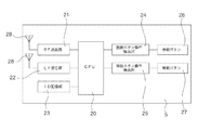
錠制御部15は、携帯器5が発信する認証用IDの認証を条件として電気錠部4の施解錠状態を遷移させる。図2に示すように、携帯器5は、制御部20(CPU)により制御されるRF送出部21、LF受信部22、携帯器固有の認証用IDが格納されるID記憶部23、施錠ボタン操作検出部24、および解錠ボタン操作検出部25を有する。   The lock control unit 15 shifts the locking / unlocking state of the electric lock unit 4 on condition that the authentication ID transmitted from the portable device 5 is authenticated. As shown in FIG. 2, the portable device 5 includes an RF transmission unit 21, an LF reception unit 22, an ID storage unit 23 storing an authentication ID unique to the portable device, and a lock button. An operation detection unit 24 and an unlock button operation detection unit 25 are provided.

携帯器5には、利用者により操作可能な施錠ボタン26と解錠ボタン27とが配置されており、いずれかへの操作が施解錠ボタン操作検出部25により検出されると、CPU20は、ID記憶部23内の認証用ID、および施解錠の区別を含む認証用無線信号(認証用ID信号)を生成してRF送出部21に出力し、アンテナ28から発信する。   The portable device 5 is provided with a locking button 26 and an unlocking button 27 that can be operated by the user. When an operation on either one is detected by the locking / unlocking button operation detection unit 25, the CPU 20 An authentication wireless signal (authentication ID signal) including the authentication ID in the storage unit 23 and the distinction between locking and unlocking is generated, output to the RF transmission unit 21, and transmitted from the antenna 28.

また、携帯器5は、扉用錠装置から出力される応答要求信号を受信するLF受信部22を有しており、LF受信部22が応答要求信号を受信すると、CPU20は、携帯器5側の施解錠ボタン操作による交信開始時と同様に認証用ID信号をセットし、RF送出部21から出力する。   Moreover, the portable device 5 has an LF receiving unit 22 that receives a response request signal output from the door lock device. When the LF receiving unit 22 receives the response request signal, the CPU 20 The authentication ID signal is set and output from the RF transmitter 21 in the same manner as when communication is started by operating the lock / unlock button.

上記錠制御部15は、アクティブモード、パッシブモード、および先読みモードにより電気錠部4、ラッチ部10を制御する。アクティブモードは、利用者が携帯器5に配置された施解錠ボタン27を操作することによる施解錠操作モードであり、携帯器5から出力された認証用ID信号に対する認証が成立すると、操作されたボタン種に応じて施解錠操作が行われる。   The lock control unit 15 controls the electric lock unit 4 and the latch unit 10 in an active mode, a passive mode, and a look-ahead mode. The active mode is a locking / unlocking operation mode in which the user operates the locking / unlocking button 27 disposed on the portable device 5, and is operated when authentication for the authentication ID signal output from the portable device 5 is established. Locking / unlocking operation is performed according to the button type.

パッシブモードは、扉2側に配置された施解錠ボタン27を操作することによる施解錠操作モードであり、施解錠ボタン27を操作すると、錠制御部15は携帯器5に応答要求信号を出力し、これに応答した携帯器5から出力される認証用ID信号に対する認証成立を条件に施解錠操作が行われる。   The passive mode is a locking / unlocking operation mode by operating the locking / unlocking button 27 arranged on the door 2 side. When the locking / unlocking button 27 is operated, the lock control unit 15 outputs a response request signal to the portable device 5. In response to this, the locking / unlocking operation is performed on the condition that the authentication for the authentication ID signal output from the portable device 5 is established.

これに対し、先読みモードは、錠制御部15から所定時間間隔で出力される応答要求信号に基づく解錠操作モードであり、利用者による明示的な操作を要することなく解錠操作が開始される点でアクティブモード、およびパッシブモードと相違する。   In contrast, the prefetch mode is an unlocking operation mode based on response request signals output from the lock control unit 15 at predetermined time intervals, and the unlocking operation is started without requiring an explicit operation by the user. This is different from the active mode and passive mode.

図3に錠制御部15の機能ブロック図を示す。錠制御部15は、制御部(CPU29)に接続されるID記憶部31、RF受信部31、認証部32、施錠ボタン操作検出部33、および解錠ボタン操作検出部25を有する。扉2に配置された施解錠ボタン16、17への操作が施錠ボタン操作検出部33、あるいは解錠ボタン操作検出部34により検出されると、パッシブ動作が開始される。パッシブ動作が開始されると、CPU29は応答要求信号をLF送出部35にセットし、アンテナ36を経由して携帯器5に送信する。応答要求信号には、操作された施解錠ボタン16、17に対応する施解錠識別信号が付与され、応答要求信号出力後、CPU29は所定時間、RF受信部31からの出力を監視して携帯器5からのレスポンスを待ち、携帯器5からの認証用ID信号を受信すると、認証部32に出力する。   FIG. 3 shows a functional block diagram of the lock control unit 15. The lock control unit 15 includes an ID storage unit 31, an RF reception unit 31, an authentication unit 32, a lock button operation detection unit 33, and an unlock button operation detection unit 25 connected to the control unit (CPU 29). When an operation on the unlocking buttons 16 and 17 arranged on the door 2 is detected by the locking button operation detecting unit 33 or the unlocking button operation detecting unit 34, a passive operation is started. When the passive operation is started, the CPU 29 sets a response request signal in the LF transmission unit 35 and transmits it to the portable device 5 via the antenna 36. The response request signal is given a lock / unlock identification signal corresponding to the operated lock / unlock buttons 16, 17, and after outputting the response request signal, the CPU 29 monitors the output from the RF receiver 31 for a predetermined time. When a response from 5 is received and an authentication ID signal is received from the portable device 5, it is output to the authentication unit 32.

認証用ID信号を受領した認証部32は、認証用IDがID記憶部31内に存在するか否かを判定し、存在する場合に認証成立信号をCPU29に出力する。認証成立信号を受領したCPU29は、上記施解錠種信号に基づき、デッドボルト制御部(電気錠制御部7)に施錠、あるいは解錠信号をセットし、デッドボルト制御部7に接続されるデッドボルト駆動用アクチュエータ1を駆動する。   Upon receiving the authentication ID signal, the authentication unit 32 determines whether or not the authentication ID exists in the ID storage unit 31, and if it exists, outputs an authentication establishment signal to the CPU 29. Upon receiving the authentication establishment signal, the CPU 29 sets the lock or unlock signal in the dead bolt control unit (electric lock control unit 7) based on the lock / unlock type signal, and the dead bolt connected to the dead bolt control unit 7 Drive actuator 1 is driven.

また、上述したパッシブ動作、および後述する先読み動作が行われていないときに、RF受信部31に認証可能な認証用ID信号を受信した場合、アクティブ動作が開始する。アクティブモード下で認証用ID信号を受信したCPU29は、上述したパッシブ動作と同様に、認証部32での認証成立を条件に、デッドボルト3を駆動する。   In addition, when an authentication ID signal that can be authenticated is received by the RF reception unit 31 when the above-described passive operation and a pre-reading operation described later are not performed, the active operation starts. The CPU 29 that has received the authentication ID signal in the active mode drives the dead bolt 3 on the condition that the authentication unit 32 establishes the authentication, as in the above-described passive operation.

さらに、錠制御部15は先読み部6を有する。先読み部6は、所定期間間隔で応答要求信号の出力タイミング情報を出力する計時部37を有し、出力タイミング情報を受信したCPU29は、応答要求信号をセットしてLF送出部35から出力し、パッシブ動作と同様に、認証用ID信号の認証に備える。   Further, the lock control unit 15 has a prefetching unit 6. The prefetching unit 6 has a timing unit 37 that outputs the output timing information of the response request signal at predetermined time intervals, and the CPU 29 that has received the output timing information sets the response request signal and outputs it from the LF sending unit 35. Similar to the passive operation, it prepares for authentication of the authentication ID signal.

応答要求信号に対する認証が成立すると、電気錠部4の駆動を行い、さらに、認証成立信号を先読み部6の認証結果格納部38に格納する。認証結果格納部38は、先読みモード下で認証可否信号が出力されるたびに、最新値に書き替えられる。   When the authentication for the response request signal is established, the electric lock unit 4 is driven, and the authentication establishment signal is stored in the authentication result storage unit 38 of the prefetch unit 6. The authentication result storage unit 38 is rewritten to the latest value every time an authentication enable / disable signal is output in the prefetch mode.

また、錠制御部15には、扉2の開閉状態を検出するための扉開閉検出部40が設けられ、扉2側に固定された扉開閉検出スイッチ39に接続される。開扉状態での施解錠、とりわけ電気錠部4に対する施錠操作は、閉扉操作に伴うデッドボルト3の破損の原因となるために、錠制御部15による制御は、扉開閉検出部40における扉閉信号の検出を条件とする。   The lock control unit 15 is provided with a door open / close detection unit 40 for detecting the open / closed state of the door 2 and is connected to a door open / close detection switch 39 fixed to the door 2 side. Locking / unlocking in the opened state, in particular, locking operation on the electric lock unit 4 may cause the dead bolt 3 to be damaged due to the closing operation, and therefore the control by the lock control unit 15 is performed by the door opening / closing detection unit 40. The condition is signal detection.

さらに錠制御部15は、ラッチ制御部41と、扉操作ハンドル14に組み込まれた接触センサ11(静電容量センサ)に接続されるハンドル操作検出部43とを備える。ハンドル操作検出部43が利用者の扉操作ハンドル14への操作を検知すると、ラッチ制御部41は、解錠状態検出スイッチ43の出力を監視する解錠状態検出部44の状態からデッドボルト3の状態を検出し、デッドボルト3の解錠位置への移動完了が確認されると、ラッチ駆動用アクチュエータ13にロック、ロック解除信号を出力し、ラッチストッパ12を駆動する。   Furthermore, the lock control unit 15 includes a latch control unit 41 and a handle operation detection unit 43 connected to the contact sensor 11 (capacitance sensor) incorporated in the door operation handle 14. When the handle operation detection unit 43 detects the user's operation on the door operation handle 14, the latch control unit 41 detects the output of the unlocked state detection switch 43 from the state of the unlocked state detection unit 44. When the state is detected and the completion of the movement of the dead bolt 3 to the unlocked position is confirmed, a lock / unlock signal is output to the latch driving actuator 13 to drive the latch stopper 12.

ラッチストッパ12のロック解除動作に先立ってデッドボルト3の移動済み状態を確認することによって、電気錠部4を施錠状態から解錠状態に移行させる際のデッドボルト3の背圧による作動不良を防止することができる。   Prior to the unlocking operation of the latch stopper 12, the dead bolt 3 is confirmed to be moved to prevent malfunction due to the back pressure of the dead bolt 3 when the electric lock 4 is shifted from the locked state to the unlocked state. can do.

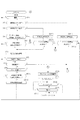
図4、5、6に上記錠制御部4の動作を示す。錠制御部15における制御は、先読み部6における所定時間間隔での応答要求信号の出力、これに対する携帯器5からのレスポンスの待ち受け、レスポンスがあった場合の認証、および電気錠部4の駆動動作という一連の動作を行いつつ、動作途中に利用者からの明示的な施解錠指示、すなわち、アクティブ、あるいはパッシブ操作があった場合、これらを優先的に処理するように進められる。   The operation of the lock control unit 4 is shown in FIGS. The control in the lock control unit 15 includes: output of a response request signal at a predetermined time interval in the prefetch unit 6; waiting for a response from the portable device 5 in response thereto; authentication when there is a response; and driving operation of the electric lock unit 4 In the middle of the operation, if there is an explicit locking / unlocking instruction from the user during the operation, that is, if there is an active or passive operation, it is advanced to process these preferentially.

まず、運用開始によりCPU29は扉開閉検出部40の出力を監視する(ステップS1)。ステップS1で扉2閉信号が検出されると、パッシブ操作の検出のために、施錠ボタン操作検出部33、および解錠ボタン検出部34の出力を確認し(ステップS2、S3)、これらの出力がない場合、RF受信部31の出力確認、RF受信部31の出力があった場合、受信した認証用ID信号の認証の可否を判定してアクティブ操作を検出する(ステップS4)。なお、この実施の形態においては、パッシブ操作による解錠命令は、扉2の解錠ボタン17への操作によって行う場合が示されているが、扉操作ハンドル14が先読み動作中のラッチストッパ解除動作のトリガとして使用されていないタイミング、すなわち、後述するように、解錠状態検出スイッチ43が解錠状態を検出していない場合には、扉操作ハンドル14を解錠ボタンとして使用することもできる。   First, when the operation starts, the CPU 29 monitors the output of the door opening / closing detection unit 40 (step S1). When the door 2 closing signal is detected in step S1, the outputs of the locking button operation detection unit 33 and the unlocking button detection unit 34 are confirmed for detection of passive operation (steps S2 and S3). If there is no output, the output of the RF receiver 31 is confirmed, and if there is an output of the RF receiver 31, whether or not the received authentication ID signal can be authenticated is determined to detect an active operation (step S4). In this embodiment, the unlocking command by the passive operation is shown to be performed by operating the unlocking button 17 of the door 2, but the latch stopper releasing operation during the pre-reading operation of the door operation handle 14 is shown. When the unlocking state detection switch 43 does not detect the unlocking state, as described later, the door operation handle 14 can also be used as the unlocking button.

これらステップS2、3、4において利用者による明示的な施解錠操作が検出されなかった場合、図示しないルーチンにより所定時間間隔をおいて出力されている先読み動作用の応答要求信号に対する携帯器5の応答を検出することにより、錠制御部15との交信エリアの利用者の進入を検出する(ステップS5)。   When an explicit locking / unlocking operation by the user is not detected in these steps S2, S3, S4, the portable device 5 responds to a response request signal for a prefetching operation output at a predetermined time interval by a routine not shown. By detecting the response, the entry of the user in the communication area with the lock control unit 15 is detected (step S5).

ステップS5で先読み動作による携帯器5の認証が行われると、認証結果格納部38に認証成立情報を格納するとともに、デッドボルト駆動用アクチュエータ1を駆動して電気錠部4を解錠状態に移行させ(ステップS6)、次いで、解錠スイッチ検出部により解錠動作の完了を検出する(ステップS7)。ステップS7で解錠動作の完了が確認されると、まず、利用者による明示的な反対操作、すなわち、アクティブ、あるいはパッシブ操作による施錠操作がないことを確認した後(ステップS8)、静電容量センサ11の出力を検知する(ステップS9)。ステップS8で施錠操作が検出されると、図6に示す電気錠部施錠ルーチン(ステップS4-12)が実行される。   When authentication of the portable device 5 is performed in step S5, the authentication establishment information is stored in the authentication result storage unit 38, and the dead bolt driving actuator 1 is driven to shift the electric lock unit 4 to the unlocked state. Next, the completion of the unlocking operation is detected by the unlocking switch detection unit (step S7). When the completion of the unlocking operation is confirmed in step S7, first, after confirming that there is no explicit opposite operation by the user, that is, no locking operation by active or passive operation (step S8), the capacitance The output of the sensor 11 is detected (step S9). When a locking operation is detected in step S8, an electric lock portion locking routine (step S4-12) shown in FIG. 6 is executed.

また、ステップS9において扉操作ハンドル14への操作が検出されると、ラッチ駆動用アクチュエータ13を駆動してラッチストッパ12のロック状態を解除し(ステップS10)、解除時間を制限するためのタイマーをセットする。ステップS11でセットした時間が経過すると(ステップS12)、扉開閉検出部40によって扉2が開いていることを確認した後(ステップS13)、ラッチストッパ12をロック状態に移行させ(ステップS14)、開始ステップに戻る。   When an operation on the door operation handle 14 is detected in step S9, the latch driving actuator 13 is driven to release the locked state of the latch stopper 12 (step S10), and a timer for limiting the release time is set. set. When the time set in step S11 elapses (step S12), the door opening / closing detection unit 40 confirms that the door 2 is open (step S13), and then the latch stopper 12 is shifted to the locked state (step S14). Return to start step.

一方、ステップS9で扉操作ハンドル14への操作が検出されなかった場合には、認証結果格納部38での結果情報が認証不成立情報で書き替えられるのを待って(ステップS9-1)、電気錠部4を施錠状態に移行させた後(ステップS9-2)、開始ステップに戻る。   On the other hand, when the operation to the door operation handle 14 is not detected in step S9, it waits for the result information in the authentication result storage unit 38 to be rewritten with the authentication failure information (step S9-1). After shifting the lock part 4 to the locked state (step S9-2), the process returns to the start step.

これに対し、ステップS2で扉2の施錠ボタン操作が検出されると、CPU29はLF送出部35に応答要求信号をセットして携帯器5に応答要求信号を出力する(ステップS2-1)。この応答要求信号に対する携帯器5からのレスポンスがあり、認証部32での認証が成立すると(ステップS2-2)、電気錠部施錠ルーチン(ステップS4-12)が実行され、認証が成立しなかった場合には、開始ステップ(ステップS1)が実行される。   On the other hand, when the lock button operation of the door 2 is detected in step S2, the CPU 29 sets a response request signal in the LF sending unit 35 and outputs a response request signal to the portable device 5 (step S2-1). When there is a response from the portable device 5 in response to this response request signal and authentication in the authentication unit 32 is established (step S2-2), an electric lock portion locking routine (step S4-12) is executed, and authentication is not established. In the case where it is found, the start step (step S1) is executed.

また、ステップS3で扉2の解錠ボタン操作が検出されると、携帯器5に応答要求信号を出力した後(ステップS3-1)、この応答要求信号に対する携帯器5からのレスポンスを待ち(ステップS3-2)、携帯器5からの認証用IDに対する認証が成立しなかった場合には、開始ステップ(ステップS1)が実行される。これに対し、携帯器5の認証が成立すると、ステップS6以下の処理が実行される。   When the unlock button operation of the door 2 is detected in step S3, a response request signal is output to the portable device 5 (step S3-1), and a response from the portable device 5 to the response request signal is waited ( Step S3-2) When the authentication for the authentication ID from the portable device 5 is not established, the start step (Step S1) is executed. On the other hand, when the authentication of the portable device 5 is established, the processing after step S6 is executed.

さらに、ステップS4でアクティブ操作が検出されると施解錠種を判定し(ステップS4-1)、施錠要求であるときには電気錠部施錠ルーチン(ステップS4-12)を実行する。また、ステップS4-1で解錠要求が検出された場合には、電気錠部4を解錠駆動し(ステップS4-2)、デッドボルト3の解錠位置への移動を確認した後(ステップS4-3)、扉操作ハンドル14の操作によるラッチ部10の解除動作可能時間を設定するために計時を開始し(ステップS4-4)、タイムアップと同時に電気錠部4を施錠状態に復帰させる(ステップS4-5、4-6)。   Further, when an active operation is detected in step S4, the type of locking / unlocking is determined (step S4-1), and when it is a locking request, an electric lock portion locking routine (step S4-12) is executed. If an unlock request is detected in step S4-1, the electric lock unit 4 is unlocked (step S4-2), and the movement of the dead bolt 3 to the unlock position is confirmed (step S4-2). S4-3), the time measurement is started to set the time when the latch unit 10 can be released by the operation of the door operation handle 14 (step S4-4), and the electric lock unit 4 is returned to the locked state at the same time. (Steps S4-5, 4-6).

扉操作ハンドル14の静電容量センサ検出ルーチン内では、タイムアップ前の明示的な施解錠処理の検出が行われ、パッシブ操作による施錠要求が検出された場合(ステップS4-7、4-7-1、4-7-2、4-7-3)には電気錠部4を施錠状態に移行させた後(ステップS4-7-4)、開始ステップに戻り、アクティブ操作による施錠操作が検出された場合には(ステップS4-9、S4-10、S4-11)、電気錠部施錠ルーチン(ステップS4-12)が実行される。   In the capacitance sensor detection routine of the door operation handle 14, an explicit locking / unlocking process is detected before the time is up, and a locking request by a passive operation is detected (steps S4-7, 4-7-). 1, 4-7-2, 4-7-3), after the electric lock 4 is shifted to the locked state (step S4-7-4), the process returns to the start step, and the locking operation by the active operation is detected. If this happens (steps S4-9, S4-10, S4-11), the electric lock portion locking routine (step S4-12) is executed.

さらに、計時ルーチン中に解錠要求があった場合には(ステップS4-7-3、S4-10)、タイマーを設定し直すことにより自動施錠(ステップS4-6)までの時間が延長される。   Furthermore, when there is a request for unlocking during the timing routine (steps S4-7-3, S4-10), the time until automatic locking (step S4-6) is extended by resetting the timer. .

また、上記計時ルーチン内で扉操作ハンドル14が操作されて静電容量センサ11により検出されると(ステップS4-8)、ステップS10以下が実行されてラッチストッパ12が解除される。   Further, when the door operation handle 14 is operated and detected by the capacitance sensor 11 within the above timing routine (step S4-8), steps S10 and after are executed and the latch stopper 12 is released.

図6に示すように、上記電気錠部施錠ルーチンは、電気錠部4への施錠駆動により開始され(ステップS4-12)、次いで、利用者による明示的な施解錠操作の検出時間を設定するためのタイマーが設定される(ステップS4-13)。タイマーによる設定時間内にパッシブ操作(ステップS4-15-1、S4-15-2、S4-17)、あるいはアクティブ操作(ステップS4-16、S4-17)が検出され、施錠要求である場合には計時を再開して実質的にタイマーを延長し、解錠要求である場合には、ステップS4-2から始まる電気錠部4の解錠動作ルーチンが実行される。   As shown in FIG. 6, the electric lock part locking routine is started by driving the electric lock part 4 to lock (step S4-12), and then a detection time of an explicit locking / unlocking operation by the user is set. Is set for the timer (step S4-13). When a passive operation (steps S4-15-1, S4-15-2, S4-17) or an active operation (steps S4-16, S4-17) is detected within the set time by the timer and the request is a locking request Resumes the time measurement and substantially extends the timer. If the request is an unlock request, the unlocking operation routine of the electric lock unit 4 starting from step S4-2 is executed.

図7以下に電気錠部4とラッチ部10の詳細を示す。図示の例は、電気錠部4の錠ケース18と、ラッチ部10のラッチケース19を連結して形成されたものが示されているが、双方に機械的伝力関係はないために、離接して扉2に固定することも可能である。   Details of the electric lock 4 and the latch 10 are shown in FIG. In the example shown in the figure, the lock case 18 of the electric lock part 4 and the latch case 19 of the latch part 10 are connected to each other. It is also possible to contact and fix to the door 2.

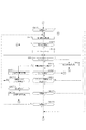
図7、8に示すように、電気錠部4のデッドボルト駆動用アクチュエータ1にはモータが使用され、モータ1の駆動力は、モータ1とともにギアボックス45内に収容されるギア列45、およびラック47を介してデッドボルト操作カム48に伝達される。デッドボルト操作カム48には、アーム48aが突設されるとともに、中心部には、図外のシリンダ錠、あるいはサムターン装置による手動施解錠操作が可能なように、シリンダ錠等の連結孔48bが形成される。   As shown in FIGS. 7 and 8, a motor is used for the dead bolt driving actuator 1 of the electric lock portion 4, and the driving force of the motor 1 is a gear train 45 accommodated in the gear box 45 together with the motor 1, and This is transmitted to the dead bolt operation cam 48 through the rack 47. The dead bolt operation cam 48 is provided with an arm 48a, and a connecting hole 48b such as a cylinder lock is provided at the center so that a cylinder lock (not shown) or a manual lock / unlock operation by a thumb turn device can be performed. It is formed.

また、電気錠部4のデッドボルト3はU字断面形状を有し、上記デッドボルト操作カム48のアーム48aの作動領域に干渉する位置に施錠用被押動部3aと、解錠用被押動部3bとが、ギアボックス45に対向する位置にストッパ段部3cが各々一体形成される。   Further, the dead bolt 3 of the electric lock portion 4 has a U-shaped cross-sectional shape, and the locked driven portion 3a and the unlocked pressed portion are disposed at positions that interfere with the operating region of the arm 48a of the dead bolt operating cam 48. Stopper step portions 3 c are integrally formed at positions where the moving portion 3 b faces the gear box 45.

図8(a)に示すようにデッドボルト3が錠ケース18から突出する施錠位置からモータ1を解錠方向に駆動すると、デッドボルト操作カム48が時計回りに回転する。デッドボルト操作カム48の回転によりアーム48aが解錠用被押動部3bに干渉した後、後方に押し出してデッドボルト3を解錠位置に移動させる。   As shown in FIG. 8A, when the motor 1 is driven in the unlocking direction from the locking position where the dead bolt 3 protrudes from the lock case 18, the dead bolt operation cam 48 rotates clockwise. The arm 48a interferes with the unlocking driven part 3b by the rotation of the deadbolt operation cam 48, and then pushes backward to move the deadbolt 3 to the unlocking position.

この解錠状態からモータ1を施錠方向に駆動すると、図8(a)に示すように、デッドボルト操作カム48が反時計方向に回転する。デッドボルト操作カム48の回転に伴ってアーム48aが施錠用被押動部3aを押し付け、デッドボルト3を施錠位置に移動させる。   When the motor 1 is driven in the locking direction from this unlocked state, the deadbolt operation cam 48 rotates counterclockwise as shown in FIG. As the deadbolt operation cam 48 rotates, the arm 48a presses the locking driven portion 3a and moves the deadbolt 3 to the locking position.

また、デッドボルト3には鎌部材49が枢軸50周りに回転自在に連結され、図7(b)に示すように、鎌部材49は施錠状態において扉枠8に開設されたストライク開口8aに係止し、扉枠8が図7(b)に示すF方向に引張られたときのデッドボルト3の抜去を防止する。この鎌部材49は一端部に作動突部49aを有しており、デッドボルト3が施錠位置から解錠位置に移動するときに錠ケース18の干渉突部18aに当接して鎌部材49をストライク開口8aとの係止解除位置側に回転させる。   Further, a sickle member 49 is rotatably connected to the dead bolt 3 around the pivot 50, and the sickle member 49 is engaged with a strike opening 8a opened in the door frame 8 in a locked state, as shown in FIG. 7B. The dead bolt 3 is prevented from being removed when the door frame 8 is pulled in the direction F shown in FIG. The sickle member 49 has an operating projection 49a at one end, and strikes the sickle member 49 by contacting the interference projection 18a of the lock case 18 when the dead bolt 3 moves from the locked position to the unlocked position. Rotate to the unlocking position side with the opening 8a.

デッドストッパ51のギアボックス45への接近は、デッドストッパ51に固定された永久磁石51aと、ギアボックス45内に固定されたホール素子からなる解錠状態検出スイッチ43により検出され、デッドボルト3が解錠状態にあることが検知される。   The approach of the dead stopper 51 to the gear box 45 is detected by an unlocking state detection switch 43 comprising a permanent magnet 51a fixed to the dead stopper 51 and a Hall element fixed in the gear box 45, and the dead bolt 3 is It is detected that the tablet is unlocked.

図9、10に示すように、ラッチ部10のラッチケース19には、前方と上下側壁が開放されるともに、後端がバネ受け壁52により閉塞されたラッチ保持筒53が固定され、ラッチ9はこのラッチ保持筒53内に前後移動自在に収容される。ラッチ9は、前端部にラッチ9の移動方向に平行な係止面と、この係止面に鋭角で交差するストッパ面とを有し、上下が水平面からなる三角柱形状のブロック部9aを備え、ブロック部9aをラッチ保持筒53の前方開口53cから露出させた姿勢でラッチ保持筒53内に挿入される。   As shown in FIGS. 9 and 10, a latch holding cylinder 53 whose front and upper and lower side walls are opened and whose rear end is closed by a spring receiving wall 52 is fixed to the latch case 19 of the latch portion 10. Is accommodated in the latch holding cylinder 53 so as to be movable back and forth. The latch 9 includes a triangular prism-shaped block portion 9a having a locking surface parallel to the moving direction of the latch 9 at a front end portion and a stopper surface intersecting the locking surface at an acute angle, and whose upper and lower sides are horizontal surfaces. The block portion 9 a is inserted into the latch holding cylinder 53 with the posture exposed from the front opening 53 c of the latch holding cylinder 53.

また、ラッチ9にはラッチ保持筒53の上下側壁開口53a、53b内に張り出すストッパアーム9b、9bが後方に向けて突設され、これら一対のストッパアーム9b、9bに挟まれるようにしてスライダ54がラッチ保持筒53内に前後移動自在に配置される。スライダ54と上記バネ受け壁52との間には圧縮スプリング55が装着され、ラッチ9は、スライダ54により前方に付勢される。図10(b)に示すように、圧縮スプリング55は、ストッパ面寄りに偏位して配置される。   Further, the latch 9 is provided with stopper arms 9b, 9b projecting rearward from the upper and lower side wall openings 53a, 53b of the latch holding cylinder 53, and is slid between the pair of stopper arms 9b, 9b. 54 is disposed in the latch holding cylinder 53 so as to be movable back and forth. A compression spring 55 is mounted between the slider 54 and the spring receiving wall 52, and the latch 9 is urged forward by the slider 54. As shown in FIG. 10B, the compression spring 55 is arranged to be deviated closer to the stopper surface.

さらに、ブロック部9aの上下面にはラッチ保持筒53の上下側壁開口53a、53b内に突出するカム突起9dが突設され、このカム突起9dに正対するように、上下側壁開口53a、53bの前端面にはカム受け面53dが形成される。   Furthermore, cam projections 9d projecting into the upper and lower side wall openings 53a and 53b of the latch holding cylinder 53 are provided on the upper and lower surfaces of the block portion 9a, and the upper and lower side wall openings 53a and 53b are opposed to the cam projection 9d. A cam receiving surface 53d is formed on the front end surface.

図11(a)に示すように、ラッチ9は扉2の開放方向(図11(a)における矢印O方向)に係止面を向けた係止姿勢で扉枠8側のストライク開口8aに係止される。図7(a)に示すように、ラッチ9とデッドボルト3とが各々ストライク開口8a、8bに係止した状態で、ラッチ9と対応するストライク開口8bとの開扉方向の間隙(δ0)は、デッドボルト3と対応するストライク開口8aとの間隙(δ1)より小寸に設定されており、開扉操作が行われた場合、ラッチ9がデッドボルト3に先立ってストライク開口8bに当接する。   As shown in FIG. 11 (a), the latch 9 is engaged with the strike opening 8a on the door frame 8 side in a locking posture with the locking surface facing the door 2 opening direction (the direction of arrow O in FIG. 11 (a)). Stopped. As shown in FIG. 7A, in the state where the latch 9 and the dead bolt 3 are engaged with the strike openings 8a and 8b, the gap (δ0) in the door opening direction between the latch 9 and the corresponding strike opening 8b is When the door opening operation is performed, the latch 9 is brought into contact with the strike opening 8b prior to the dead bolt 3. When the door opening operation is performed, the latch 9 contacts the strike opening 8b.

解錠状態において、図11(a)に示すストライク開口8bへの係止状態から扉2に開放方向の操作力が付与されると、ラッチ9の係止面はストライク開口8bから矢印Oと反対方向の力を受ける。この結果、ラッチ9は、図11(b)に示すように、ストッパ面がラッチ保持筒53の内壁面に当接するまで時計回りに回転して没入可能姿勢に移行する。この状態からさらに開扉操作を続けると、開扉方向線に対して斜めとなった係止面はストライク開口8aの周縁からラッチ9没入方向の分力を受け、ラッチ9は圧縮スプリング55の反力に抗して扉2内に没入してストライク開口8bから脱離する(図11(c)参照)。   In the unlocked state, when an operation force in the opening direction is applied to the door 2 from the locked state to the strike opening 8b shown in FIG. 11 (a), the locking surface of the latch 9 is opposite to the arrow O from the strike opening 8b. Receive direction force. As a result, as shown in FIG. 11B, the latch 9 rotates clockwise until the stopper surface comes into contact with the inner wall surface of the latch holding cylinder 53 and shifts to the retractable posture. If the door opening operation is further continued from this state, the engaging surface inclined with respect to the door opening direction line receives the component force in the latch 9 immersion direction from the periphery of the strike opening 8a, and the latch 9 is opposite to the compression spring 55. It is immersed in the door 2 against the force and detached from the strike opening 8b (see FIG. 11C).

この後、扉2が扉枠8から完全に離れると、圧縮スプリング55の復元力によりラッチ9は前方に押し出され、カム突起9dはカム受け面53dに当接する。図11(c)に示す姿勢で、ラッチ9とスライダ54との接触部は、カム受け面53dとカム突起9dとの接触部に対して開扉方向に偏位しているために、ラッチ9には反時計回りに回転力が作用し、ラッチ9は、自動的に係止姿勢に復帰する。   Thereafter, when the door 2 is completely separated from the door frame 8, the latch 9 is pushed forward by the restoring force of the compression spring 55, and the cam projection 9d comes into contact with the cam receiving surface 53d. In the posture shown in FIG. 11C, the contact portion between the latch 9 and the slider 54 is offset in the door opening direction with respect to the contact portion between the cam receiving surface 53d and the cam projection 9d. , A rotational force acts counterclockwise, and the latch 9 automatically returns to the locked posture.

開扉状態でラッチ9が係止姿勢にあるとき、ストッパ面が扉枠8に正対しているために、この状態から閉扉2操作を行うと、ラッチ9はストッパ面からの没入分力により一旦没入した後、ストライク開口8bに係止する。   When the latch 9 is in the locked position in the open state, the stopper surface faces the door frame 8. Therefore, when the closing door 2 is operated from this state, the latch 9 is temporarily suspended by the immersion force from the stopper surface. After being immersed, it is locked to the strike opening 8b.

図10に示すように、閉扉2状態においてラッチ9を係止姿勢に維持し、ラッチ9の係止状態を維持するためのラッチストッパ12は、ラッチ9のストッパアーム9bの移動を拘束してラッチ9の回転を規制する。図9に示すように、ラッチストッパ12はラッチケース19に連結されるストッパレバー56の一端に形成される。ストッパレバー56は枢軸57周りに回転自在であり、トーションスプリング58によりラッチストッパ12がラッチ9を拘束するストッパセット方向に付勢される。   As shown in FIG. 10, the latch stopper 12 for maintaining the latch 9 in the locked posture in the closed door 2 state and maintaining the latched state of the latch 9 restrains the movement of the stopper arm 9b of the latch 9 and latches. 9 is restricted. As shown in FIG. 9, the latch stopper 12 is formed at one end of a stopper lever 56 connected to the latch case 19. The stopper lever 56 is rotatable around the pivot 57 and is biased by the torsion spring 58 in the stopper setting direction in which the latch stopper 12 restrains the latch 9.

ラッチ駆動用アクチュエータ13にはソレノイドが使用される。ソレノイド13は、図9(a)に示す非励磁状態がラッチストッパセット状態、図9(b)に示す励磁状態がストッパ解除状態に対応する。このソレノイド13の駆動力は、ソレノイド13の駆動軸13aに連結されるソレノイドレバー59、および中継レバー60を経由して上記ストッパレバー56に伝達される。   A solenoid is used for the latch driving actuator 13. In the solenoid 13, the non-excitation state shown in FIG. 9A corresponds to the latch stopper set state, and the excitation state shown in FIG. 9B corresponds to the stopper release state. The driving force of the solenoid 13 is transmitted to the stopper lever 56 via the solenoid lever 59 connected to the driving shaft 13 a of the solenoid 13 and the relay lever 60.

ソレノイドレバー59は、枢軸61周りに、中継レバー60は枢軸62周りに各々回転自在であり、ソレノイドレバー59から中継レバー60への動力伝達は、ソレノイドレバー59に形成される突部59aにより中継レバー60の第1ピン60aを押し付けることにより行われる。また、中継レバー60とストッパレバー56とは、中継レバー60に立設した第2ピン60bをストッパレバー56の長孔56aに移動自在に挿通させて連結される。   The solenoid lever 59 is rotatable around the pivot 61 and the relay lever 60 is rotatable around the pivot 62. Power transmission from the solenoid lever 59 to the relay lever 60 is transmitted by a projection 59 a formed on the solenoid lever 59. This is done by pressing 60 first pins 60a. Further, the relay lever 60 and the stopper lever 56 are coupled by allowing the second pin 60 b erected on the relay lever 60 to be movably inserted into the elongated hole 56 a of the stopper lever 56.

図9(a)に示すラッチストッパ12セット状態からソレノイド13を励磁すると、図9(b)に示すように、ソレノイドレバー59は反時計方向に回転し、突部59aが第1ピン60aを押圧する。この結果、中継レバー60は時計回りに回転し、ストッパレバー56は反時計回りに回転し、ラッチストッパ12とラッチ9のストッパアーム9bとの係止が解除される。   When the solenoid 13 is excited from the latch stopper 12 set state shown in FIG. 9A, the solenoid lever 59 rotates counterclockwise as shown in FIG. 9B, and the projection 59a presses the first pin 60a. To do. As a result, the relay lever 60 rotates clockwise, the stopper lever 56 rotates counterclockwise, and the latching of the latch stopper 12 and the stopper arm 9b of the latch 9 is released.

このラッチストッパ12解除状態からソレノイド13の励磁を停止すると、駆動軸13aが図9(a)に示す突出位置に復帰してソレノイドレバー59を原位置に復帰させる。ソレノイドレバー59の復帰により、第1ピン60aへの押圧力が解除されて中継レバー60に対する反時計回りへの回転拘束が解除され、トーションスプリング58の復元力によりラッチストッパセット位置側に付勢されたストッパレバー56はラッチストッパセット位置に移動する。   When the excitation of the solenoid 13 is stopped from the latch stopper 12 released state, the drive shaft 13a returns to the protruding position shown in FIG. 9A and the solenoid lever 59 returns to the original position. By the return of the solenoid lever 59, the pressing force to the first pin 60a is released, the counterclockwise rotation restraint with respect to the relay lever 60 is released, and it is urged to the latch stopper set position side by the restoring force of the torsion spring 58. The stopper lever 56 moves to the latch stopper set position.

本発明を示す機能ブロック図である。It is a functional block diagram which shows this invention. 携帯機の機能ブロック図である。It is a functional block diagram of a portable machine. 錠制御部の機能ブロック図である。It is a functional block diagram of a lock | rock control part. 錠制御部の動作を示すフローである。It is a flow which shows operation | movement of a lock | rock control part. 錠制御部の動作を示すフローである。It is a flow which shows operation | movement of a lock | rock control part. 錠制御部の動作を示すフローである。It is a flow which shows operation | movement of a lock | rock control part. 扉用錠装置を示す図で、(a)は(b)の7A方向矢視図、(b)は断面図である。It is a figure which shows the locking device for doors, (a) is a 7A direction arrow directional view of (b), (b) is sectional drawing. 電気錠部を示す図で、(a)は施錠状態を示す図、(b)は解錠状態を示す図である。It is a figure which shows an electric lock part, (a) is a figure which shows a locked state, (b) is a figure which shows an unlocked state. ラッチ部を示す図で、(a)はラッチストッパセット状態を示す図、(b)はラッチストッパセットの解錠状態を示す図。It is a figure which shows a latch part, (a) is a figure which shows a latch stopper set state, (b) is a figure which shows the unlocking state of a latch stopper set. ラッチを示す図で、(a)は図9(a)の10A方向矢視図、(b)の10B-10B線断面図である。It is a figure which shows a latch, (a) is a 10 A direction arrow directional view of Fig.9 (a), and 10B-10B sectional view taken on the line of (b). ラッチの動作を示す図で、(a)は扉枠への係止状態を示す図、(b)は反転状態を示す図、(c)は扉への没入状態を示す図である。It is a figure which shows the operation | movement of a latch, (a) is a figure which shows the latching state to a door frame, (b) is a figure which shows a reverse state, (c) is a figure which shows the immersion state to a door.

符号の説明Explanation of symbols

1 デッドボルト駆動用アクチュエータ
2 扉
3 デッドボルト
4 電気錠部
5 携帯器
6 先読み部
7 電気錠制御部
8 扉枠
9 ラッチ
10 ラッチ部
11 操作者検出部(接触センサ)
12 ラッチストッパ
13 ラッチ駆動用アクチュエータ
14 扉操作ハンドル
DESCRIPTION OF SYMBOLS 1 Dead bolt drive actuator 2 Door 3 Dead bolt 4 Electric lock part 5 Portable device 6 Pre-reading part 7 Electric lock control part 8 Door frame 9 Latch 10 Latch part 11 Operator detection part (contact sensor)
12 Latch stopper 13 Latch drive actuator 14 Door operation handle

Claims (5)

デッドボルト駆動用アクチュエータにより施解錠位置間で駆動され、施錠位置において扉の開放操作を規制するデッドボルトを備えた電気錠部と、
利用者が所持し、応答要求信号に対して認証用ID信号を出力する携帯器に所定時間間隔で応答要求信号を出力し、受信したID信号に対する認証結果を格納する先読み部と、
前記先読み部への認証成立情報の格納を条件に電気錠部を解錠駆動し、前記先読み部の格納情報が認証不成立に変化するまで解錠状態を維持した後、施錠状態に移行させる電気錠制御部と、
扉から突出して扉枠に係止し、扉への没入状態で扉枠との係止状態を解除するラッチを備えたラッチ部とを有する扉用錠装置。
An electric lock portion that is driven between the unlocking and unlocking positions by the deadbolt driving actuator and includes a deadbolt that regulates the door opening operation at the locking position;
A pre-reading unit that outputs a response request signal at a predetermined time interval to a portable device possessed by the user and outputs an authentication ID signal in response to the response request signal, and stores an authentication result for the received ID signal;
An electric lock that unlocks the electric lock unit on condition that the authentication establishment information is stored in the pre-reading unit, maintains the unlocked state until the storage information of the pre-reading unit changes to non-authentication, and then shifts to the locking state. A control unit;
A door locking device comprising: a latch portion that includes a latch that protrudes from a door and engages with the door frame and releases the engagement with the door frame when immersed in the door.
扉または扉近傍に設置され、携帯器との交信距離に比して短い検出距離内で操作者を検出する操作者検出部を有するとともに、
前記ラッチ部は、ロック位置において前記ラッチの没入操作を規制し、ロック解除位置においてラッチの没入を許容するラッチストッパと、
電気錠部が解錠状態であること、および操作者検出部における操作者検出を条件として前記ラッチストッパをロック解除位置に駆動するラッチ駆動用アクチュエータとを有する請求項1記載の扉用錠装置。
While having an operator detection unit that is installed near the door or near the door and detects the operator within a detection distance shorter than the communication distance with the portable device,
The latch portion restricts the immersing operation of the latch at the lock position, and allows the immersion of the latch at the unlock position;
The door locking device according to claim 1, further comprising: a latch driving actuator that drives the latch stopper to an unlocked position on condition that the electric lock portion is unlocked and the operator is detected by the operator detecting portion.
前記ラッチ駆動用アクチュエータは、ラッチストッパのロック解除動作完了から所定時間経過後に再び駆動されてラッチストッパをロック位置に復帰させる請求項2記載の扉用錠装置。   3. The door locking device according to claim 2, wherein the latch driving actuator is driven again after a predetermined time has elapsed from completion of the unlocking operation of the latch stopper to return the latch stopper to the locked position. 前記操作者検出部が扉操作ハンドルに組み込まれた接触センサである請求項2または3記載の扉用錠装置。   The door locking device according to claim 2 or 3, wherein the operator detection unit is a contact sensor incorporated in a door operation handle. 前記ラッチ部は、扉枠との当接面が開扉軌跡に直交する係止姿勢と、開扉軌跡に対して斜行し、開扉操作による没入方向の分力が発生する没入可能姿勢との間を回転自在で、ラッチストッパにより係止姿勢から没入可能姿勢への移行が規制される反転ラッチ装置として形成される請求項1、2、3または4記載の扉用錠装置。   The latch portion has a locking posture in which a contact surface with the door frame is perpendicular to the opening locus, and an immersable posture in which a component force in the immersing direction is generated by skewing with respect to the opening locus. The door locking device according to claim 1, 2, 3, or 4, wherein the door locking device is formed as a reversing latch device that can freely rotate between the two and is controlled by a latch stopper from a locking posture to a retractable posture.
JP2008275469A 2008-10-27 2008-10-27 Door lock device Active JP5634671B2 (en)

Priority Applications (1)

Application Number Priority Date Filing Date Title
JP2008275469A JP5634671B2 (en) 2008-10-27 2008-10-27 Door lock device

Applications Claiming Priority (1)

Application Number Priority Date Filing Date Title
JP2008275469A JP5634671B2 (en) 2008-10-27 2008-10-27 Door lock device

Publications (2)

Publication Number Publication Date
JP2010101124A true JP2010101124A (en) 2010-05-06
JP5634671B2 JP5634671B2 (en) 2014-12-03

Family

ID=42291991

Family Applications (1)

Application Number Title Priority Date Filing Date
JP2008275469A Active JP5634671B2 (en) 2008-10-27 2008-10-27 Door lock device

Country Status (1)

Country Link
JP (1) JP5634671B2 (en)

Cited By (3)

* Cited by examiner, † Cited by third party
Publication number Priority date Publication date Assignee Title
JP2010123912A (en) * 2009-04-03 2010-06-03 Toppan Printing Co Ltd Solar cell module
JP2016065414A (en) * 2014-09-25 2016-04-28 パナソニックIpマネジメント株式会社 Electric lock apparatus
JP2019210619A (en) * 2018-05-31 2019-12-12 株式会社Lixil Fitting

Citations (8)

* Cited by examiner, † Cited by third party
Publication number Priority date Publication date Assignee Title
JPH11293975A (en) * 1998-04-04 1999-10-26 Goal Co Ltd Electric lock
JP2005127084A (en) * 2003-10-27 2005-05-19 Bunka Shutter Co Ltd Opening and closing system
JP2005240478A (en) * 2004-02-27 2005-09-08 Oki Electric Ind Co Ltd Authentication system
JP2006161505A (en) * 2004-12-10 2006-06-22 Denso Corp Smart key system for vehicle
JP2008150803A (en) * 2006-12-14 2008-07-03 Alpha Corp Door handle
JP2008179997A (en) * 2007-01-25 2008-08-07 Shibutani:Kk Reversal latch type electric lock
JP2008184780A (en) * 2007-01-29 2008-08-14 Tokai Rika Co Ltd Electric lock for building and electric lock system for building
JP2008184744A (en) * 2007-01-26 2008-08-14 Tokai Rika Co Ltd Electric lock

Patent Citations (8)

* Cited by examiner, † Cited by third party
Publication number Priority date Publication date Assignee Title
JPH11293975A (en) * 1998-04-04 1999-10-26 Goal Co Ltd Electric lock
JP2005127084A (en) * 2003-10-27 2005-05-19 Bunka Shutter Co Ltd Opening and closing system
JP2005240478A (en) * 2004-02-27 2005-09-08 Oki Electric Ind Co Ltd Authentication system
JP2006161505A (en) * 2004-12-10 2006-06-22 Denso Corp Smart key system for vehicle
JP2008150803A (en) * 2006-12-14 2008-07-03 Alpha Corp Door handle
JP2008179997A (en) * 2007-01-25 2008-08-07 Shibutani:Kk Reversal latch type electric lock
JP2008184744A (en) * 2007-01-26 2008-08-14 Tokai Rika Co Ltd Electric lock
JP2008184780A (en) * 2007-01-29 2008-08-14 Tokai Rika Co Ltd Electric lock for building and electric lock system for building

Cited By (4)

* Cited by examiner, † Cited by third party
Publication number Priority date Publication date Assignee Title
JP2010123912A (en) * 2009-04-03 2010-06-03 Toppan Printing Co Ltd Solar cell module
JP2016065414A (en) * 2014-09-25 2016-04-28 パナソニックIpマネジメント株式会社 Electric lock apparatus
JP2019210619A (en) * 2018-05-31 2019-12-12 株式会社Lixil Fitting
JP7086727B2 (en) 2018-05-31 2022-06-20 株式会社Lixil Joinery

Also Published As

Publication number Publication date
JP5634671B2 (en) 2014-12-03

Similar Documents

Publication Publication Date Title
JP5524781B2 (en) Door closer equipment
KR101836696B1 (en) Latch apparatus of tailgate for vehicle
JP5634671B2 (en) Door lock device
JP2009091746A (en) Code hole matching-type lock
JP4904494B2 (en) Key interlock device for steering column lock device
JP5007198B2 (en) Door lock device
KR200456588Y1 (en) Auto locking apparatus for sliding windows
JP5519139B2 (en) Door lock device
US20230125130A1 (en) Drive mechanism for electronic deadbolt
JP4839701B2 (en) VEHICLE LOCK CONTROL DEVICE AND LOCK CONTROL METHOD
KR200438979Y1 (en) Digital door lock
CN211549234U (en) Vehicle door opening/closing operation device
JP6853672B2 (en) Latch device and door device using it
JP7108400B2 (en) vehicle steering wheel
KR101372590B1 (en) Rotation preventive apparatus of door lever
EP3428373B1 (en) Electric lock device
JP5479217B2 (en) Locking and unlocking device for opening and closing body in article storage fixture
JP4850590B2 (en) Locking device
JP2004345455A (en) Lock device
US20220325557A1 (en) Detection and correction of insufficient locking behavior of an electronic lockset
JP6395446B2 (en) Vehicle door lock control system
JP6951843B2 (en) Latch device and door device using it
JP4595540B2 (en) Take-away prevention system
JP7046519B2 (en) Vehicle door open / close operation device
JP2019090196A (en) Vehicle door opening/closing operation device

Legal Events

Date Code Title Description
A621 Written request for application examination

Free format text: JAPANESE INTERMEDIATE CODE: A621

Effective date: 20111018

A977 Report on retrieval

Free format text: JAPANESE INTERMEDIATE CODE: A971007

Effective date: 20130104

A131 Notification of reasons for refusal

Free format text: JAPANESE INTERMEDIATE CODE: A131

Effective date: 20130514

A521 Request for written amendment filed

Free format text: JAPANESE INTERMEDIATE CODE: A523

Effective date: 20130716

Free format text: JAPANESE INTERMEDIATE CODE: A821

Effective date: 20130716

A131 Notification of reasons for refusal

Free format text: JAPANESE INTERMEDIATE CODE: A131

Effective date: 20140204

A521 Request for written amendment filed

Free format text: JAPANESE INTERMEDIATE CODE: A523

Effective date: 20140407

Free format text: JAPANESE INTERMEDIATE CODE: A821

Effective date: 20140407

TRDD Decision of grant or rejection written
A01 Written decision to grant a patent or to grant a registration (utility model)

Free format text: JAPANESE INTERMEDIATE CODE: A01

Effective date: 20141014

A61 First payment of annual fees (during grant procedure)

Free format text: JAPANESE INTERMEDIATE CODE: A61

Effective date: 20141015

R150 Certificate of patent or registration of utility model

Ref document number: 5634671

Country of ref document: JP

Free format text: JAPANESE INTERMEDIATE CODE: R150

R250 Receipt of annual fees

Free format text: JAPANESE INTERMEDIATE CODE: R250

R250 Receipt of annual fees

Free format text: JAPANESE INTERMEDIATE CODE: R250

R250 Receipt of annual fees

Free format text: JAPANESE INTERMEDIATE CODE: R250

R250 Receipt of annual fees

Free format text: JAPANESE INTERMEDIATE CODE: R250

R250 Receipt of annual fees

Free format text: JAPANESE INTERMEDIATE CODE: R250

R250 Receipt of annual fees

Free format text: JAPANESE INTERMEDIATE CODE: R250

R250 Receipt of annual fees

Free format text: JAPANESE INTERMEDIATE CODE: R250