JP2010099456A - Endodontic procedure employing simultaneous liquefaction and acoustic debridgement - Google Patents
Endodontic procedure employing simultaneous liquefaction and acoustic debridgement Download PDFInfo
- Publication number
- JP2010099456A JP2010099456A JP2009177316A JP2009177316A JP2010099456A JP 2010099456 A JP2010099456 A JP 2010099456A JP 2009177316 A JP2009177316 A JP 2009177316A JP 2009177316 A JP2009177316 A JP 2009177316A JP 2010099456 A JP2010099456 A JP 2010099456A
- Authority
- JP
- Japan
- Prior art keywords
- fluid
- ultrasonic
- flow path
- fluid flow
- tubular body
- Prior art date
- Legal status (The legal status is an assumption and is not a legal conclusion. Google has not performed a legal analysis and makes no representation as to the accuracy of the status listed.)
- Granted
Links
Images


Classifications
-
- A—HUMAN NECESSITIES
- A61—MEDICAL OR VETERINARY SCIENCE; HYGIENE
- A61C—DENTISTRY; APPARATUS OR METHODS FOR ORAL OR DENTAL HYGIENE
- A61C1/00—Dental machines for boring or cutting ; General features of dental machines or apparatus, e.g. hand-piece design
- A61C1/02—Dental machines for boring or cutting ; General features of dental machines or apparatus, e.g. hand-piece design characterised by the drive of the dental tools
- A61C1/07—Dental machines for boring or cutting ; General features of dental machines or apparatus, e.g. hand-piece design characterised by the drive of the dental tools with vibratory drive, e.g. ultrasonic
-
- A—HUMAN NECESSITIES
- A61—MEDICAL OR VETERINARY SCIENCE; HYGIENE
- A61C—DENTISTRY; APPARATUS OR METHODS FOR ORAL OR DENTAL HYGIENE
- A61C17/00—Devices for cleaning, polishing, rinsing or drying teeth, teeth cavities or prostheses; Saliva removers; Dental appliances for receiving spittle
- A61C17/02—Rinsing or air-blowing devices, e.g. using fluid jets or comprising liquid medication
-
- A—HUMAN NECESSITIES
- A61—MEDICAL OR VETERINARY SCIENCE; HYGIENE
- A61C—DENTISTRY; APPARATUS OR METHODS FOR ORAL OR DENTAL HYGIENE
- A61C17/00—Devices for cleaning, polishing, rinsing or drying teeth, teeth cavities or prostheses; Saliva removers; Dental appliances for receiving spittle
- A61C17/16—Power-driven cleaning or polishing devices
- A61C17/20—Power-driven cleaning or polishing devices using ultrasonics
-
- A—HUMAN NECESSITIES
- A61—MEDICAL OR VETERINARY SCIENCE; HYGIENE
- A61C—DENTISTRY; APPARATUS OR METHODS FOR ORAL OR DENTAL HYGIENE
- A61C5/00—Filling or capping teeth
- A61C5/40—Implements for surgical treatment of the roots or nerves of the teeth; Nerve needles; Methods or instruments for medication of the roots
Abstract
Description
係属中の出願の参照
本願は、2005年5月16日に出願された米国特許出願第11/130081号の一部継続出願であり、その出願の優先権を主張する。
マイクロフィッシュ付録の参照
本願は、マイクロフィッシュ付録においては参照されない。
This application is a continuation-in-part of US patent application Ser. No. 11/130081, filed May 16, 2005, and claims priority from that application.
Reference to the Microfish Appendix This application is not referenced in the Microfish Appendix.
本発明は、液化(liquefaction)および音波デブリッジメント(acoustic debridgement(創面切除))の同時実施によって達成される、歯内療法的根管形成に関する。 The present invention relates to endodontic root canal formation achieved by simultaneous implementation of liquefaction and acoustic debridgment.
本発明は、歯科器具に関し、詳細には、物理的/音波デブリッジメントと潅流溶液による洗い流しとによって歯根管から細菌学的物質が取り除かれる、歯根管を処理する歯内療法器具、システム、および処置、特に、病変/壊死組織を除去するために潅流を提供する装置および機器に関する。 The present invention relates to dental instruments, and in particular, endodontic instruments, systems for treating root canals, wherein bacteriological material is removed from the root canals by physical / sonic debridging and flushing with a perfusion solution, and The present invention relates to devices and devices that provide perfusion to remove treatments, particularly lesion / necrotic tissue.
歯内療法は、歯科医術の重要な部分になってきている。一方で、歯内療法処置が一般的に使用される前には、膿んだ歯は、通常、その歯の抜去だけによって処理された。しかし、歯内療法が進歩してからは、健康の大幅な増進および生理学的利益のために、患者による保有が可能となるように膿んだ歯をうまく処理することができる。歯内療法は、現代医療における大きな進歩の1つとなった。 Endodontic therapy has become an important part of dentistry. On the other hand, before the endodontic treatment was commonly used, abscessed teeth were usually treated only by removal of the teeth. However, once endodontic therapy has progressed, abscessed teeth can be successfully treated so that they can be retained by the patient for significant health gains and physiological benefits. Endodontic therapy has become one of the major advances in modern medicine.
歯内療法的根管形成は、通常、歯の歯冠部を通じて根管を開口させ、その後、可能な限り多くの歯髄物質を物理的に除去するように根管内でファイルおよびリーマを操作することを含む。この歯髄物質は、通常、感染または壊死しており、すなわち、死んだ物質であり、処置完了後に根管内に残存するそのような物質は、潜在的感染源である。この理由から、根管の適正な処理は、そのような壊死歯髄物質を可能な限り多く除去しようと試みる。ファイルおよびリーマを用いてそのような歯髄物質のかなりの部分を除去できるが、ほとんどの場合、根管内での道具の物理的操作によってそのような物質すべてを除去することは、事実上不可能である。この理由から、最近、ファイルおよびリーマが用いられた後で残存する有機歯髄物質を除去かつ/または中和するために根管を流体で潅流するまたは洗い流す処置が開発された。 Endodontic root canal formation usually opens the root canal through the crown of the tooth and then manipulates the files and reamers within the root canal to physically remove as much pulp material as possible Including that. This pulp material is usually infected or necrotic, i.e., is dead material, such material remaining in the root canal after treatment is complete is a potential source of infection. For this reason, proper treatment of the root canal attempts to remove as much of such necrotic pulp material as possible. A file and reamer can be used to remove a significant portion of such pulp material, but in most cases it is virtually impossible to remove all such material by physical manipulation of the tool in the root canal It is. For this reason, recently, treatments have been developed to perfuse or flush the root canal to remove and / or neutralize the remaining organic pulpal material after the file and reamer are used.
背景情報として、1982年5月18日に発行されたHoward Martinの米国特許第4330278号、名称「Endodontic Flow−Through Ultrasonic Instrument Holder Device」を参照することができる。このデバイスは、歯内療法処置中に洗浄流体をそれによって歯に注入できる通路を含む、歯科作業に使用される器具を保持するホルダを含むシステムを示す。本発明は、この米国特許で明示されるこの基本概念に関する改良である。 As background information, reference can be made to Howard Martin, US Pat. No. 4,330,278 issued on May 18, 1982, entitled “Endonic Flow-Through Ultrasonic Instrument Holder Device”. The device shows a system that includes a holder that holds an instrument used for dental work, including a passageway through which irrigation fluid can be injected into the tooth during an endodontic procedure. The present invention is an improvement over this basic concept as manifested in this US patent.
根管に洗浄流体を送出する現在のチップアセンブリ設計、例えば、2005年9月27日に発行されたJohn Nussteinの米国特許第6948935号、名称「Ultrasonic Dental Device」は、チップアセンブリ構成および配管アセンブリ配置ゆえに、超音波エネルギーを洗浄流体へと効果的に伝達せず、また、扱いにくいことが判明している。本発明は、また、それらのチップアセンブリ設計に関する改良でもある。 Current chip assembly designs that deliver cleaning fluid to the root canal, such as John Nusstein's US Pat. No. 6,948,935, issued September 27, 2005, is named “Ultrasonic Dental Device”. Therefore, it has been found that ultrasonic energy is not effectively transferred to the cleaning fluid and is cumbersome. The present invention is also an improvement over their chip assembly design.
本明細書の発明は、歯根管の液化および音波デブリッジメントの同時実施のためのシステムおよび方法である。該システムは、それを貫く流路を有する操作可能なハンドピースを含む。超音波エネルギー発生装置がハンドピースにしっかり固定される。可撓性注入チューブが、歯根管に挿入されるように寸法設定かつ構成される。注入チューブの近位端をハンドピースに着脱自在に添着するために連結器が使用される。加圧された洗浄流体源がハンドピースに連結されており、それによって、超音波エネルギーを付与された流体が根管内に押し込まれる。 The invention herein is a system and method for simultaneous implementation of root canal liquefaction and sonic debridging. The system includes an operable handpiece having a flow path therethrough. An ultrasonic energy generator is securely fixed to the handpiece. A flexible injection tube is sized and configured to be inserted into the root canal. A connector is used to removably attach the proximal end of the infusion tube to the handpiece. A pressurized irrigation fluid source is coupled to the handpiece, thereby pushing ultrasonically energized fluid into the root canal.
本明細書の発明における重要な改良点は、歯根管内に含まれる残屑の遊離および除去を増進する圧力パルスを使用して流体が歯根管に注入され、同時に流体圧力パルスが超音波エネルギーと重ねられる、システムの提供である。 An important improvement in the invention herein is that fluid is injected into the root canal using pressure pulses that enhance the release and removal of debris contained within the root canal, while the fluid pressure pulses overlap with the ultrasonic energy. System provision.
他の重要な改良点は、それを貫く内部流体流路を有するコントラアングル(contra−angle)チップアセンブリである。通路の一部分は、チップアセンブリインサートの受け部端によって部分的に包囲される。この配置は、流体に超音波エネルギーを直接的に伝達する働きをする。また、チップアセンブリの設計によって、供給チューブは、ハンドピースにほぼ平行に走ることができ、したがって、臨床医がハンドピースを操作するときに該臨床医の邪魔にならないところを走ることができる。 Another important improvement is a contra-angle tip assembly having an internal fluid flow path therethrough. A portion of the passage is partially surrounded by the receiving end of the chip assembly insert. This arrangement serves to transmit ultrasonic energy directly to the fluid. Also, the design of the tip assembly allows the supply tube to run substantially parallel to the handpiece and thus run out of the way of the clinician when the clinician manipulates the handpiece.
以下の、発明を実施するための形態を、諸図面および特許請求の範囲と併せて読めば、本発明のより完全な理解が得られる。 A more complete understanding of the invention can be obtained by reading the following detailed description in conjunction with the drawings and the claims.
これから記載する発明が、その利用を、添付の諸図面に示される諸部品の構造および配置の詳細だけに限定されないことが、理解されるはずである。本発明は、他の諸実施形態が可能であり、様々な方法で実践または実施可能である。本明細書で用いられる表現および用語は、説明を目的としたものであって、制限を目的としたものではない。 It should be understood that the invention to be described is not limited in its use to the details of the construction and arrangement of the parts shown in the accompanying drawings. The invention is capable of other embodiments and of being practiced or carried out in various ways. The expressions and terms used herein are for purposes of illustration and are not intended to be limiting.
諸図面によって示される要素は、後述の番号によって識別される。
諸図面、初めに図1を参照すると、典型的な歯10が断面で示されている。歯は、歯冠部12と、そこから延びる歯根14とを含む。歯冠部は、根管18および20の上端に接近するために穿孔された開口領域16を有する。これらの根管18、20は、各根管の尖端22まで延びる。
Elements shown in the drawings are identified by numbers described below.
Referring to the drawings and initially to FIG. 1, a
歯内療法の実践には、その重要部として、充填材を受け取るための根管18および20の根管形成が含まれる。そのような充填材は、通常、ガッタパーチャであるが、他の同等の材料も開発されている。根管18および20が、すべての有機物質を除去するように、成形され、可能な限り徹底的に清掃されることが重要である。そのような有機物質は、通常、歯の本来の部分として存在し、歯が形成過程でそれによって栄養供給される、歯髄物質である。そのような歯髄物質は、根管内に残って充填材によって封じ込められた場合、感染を起こし、それによって患者に問題を引き起こしかねない。根管内で生じる感染は、身体の他の部分に広がるおそれがある。この理由から、前述のように、根管18および20の範囲から可能な限り多くの歯髄および他の壊死物質を除去することが重要である。
Endodontic practices include root canal formation of
通常の歯内療法処置では、歯内療法医が、可能な限り多くの歯髄物質を除去するような形で根管を擦過して成形し、充填材を受け取るために根管を成形する必要がある。しかし、図1には示されていないが、根管18および20は、通常、歯髄物質がその中に捕らえられるおそれのある横方向に延びる裂溝および他の凹凸を有しており、したがって、物理的に擦過して成形するだけですべての歯髄物質を除去することは非常に困難である。
In a typical endodontic procedure, the endodontist needs to scrape and shape the root canal in such a way as to remove as much pulp material as possible and to shape the root canal to receive the filler. is there. However, although not shown in FIG. 1,
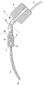
この理由から、根管が機械的に清浄化され成形された後で、該根管が洗い流される処置が生まれた。本発明の方法によって歯根管を洗い流す際に使用するために、全体的に番号24によって示されるハンドピースが用いられる。ハンドピース24は、それを貫く流路28を有する管状体部分26を含む。管状体部分の遠位端は、わずかに拡大され、雌ねじ山30を備えており、その拡大部分が番号32によって示されている。
For this reason, after the root canal has been mechanically cleaned and molded, a procedure has been born in which the root canal is washed away. A handpiece, generally designated by
拡大部分32の外端部内に、それを貫く通路36を有するカップリングナット34が螺合式に受けられる。注入チューブ38は、一体型の拡大末端部分40を有する。可撓性注入チューブは、拡大末端部分40に係合するカップリングナットの通路36内を延びており、その結果、可撓性注入チューブ38は、ハンドピース管状体部分26の外端部に連結される。可撓性注入チューブ38は、細長く、また、ここに示されるように、根管18、20の下端部分の可能な限り近くに到達するように構成された、遠位端42に向かってテーパしたものとすることができる。
A
ハンドピース24は、さらに、本体部分の一部として、超音波エネルギーを振動の形態で発生させる能力を有する超音波発生装置44を含む。超音波発生装置44からの音の振動は、ハンドピース管状体部分と可撓性注入チューブ38とに伝わる。
The
図2は、ここまでに記載したハンドピース24を示し、また、超音波発生装置44内を延びる通路46を示す。このように、通路46は、管状体部分の流路28と連通しており、該流路28は、可撓性注入チューブ38と連通する。電源コード48が、超音波発生装置44に電気エネルギーを供給する。
FIG. 2 shows the
図3は、本発明を実践する方法を図式的に示す。ハンドピース24は、可撓性注入チューブ38および超音波発生装置44とともに図式的に示されている。歯内療法処置の一環として歯を洗い流す目的で図1に示されるように歯根管に流入させるために、ハンドピース26を通じて、またそれにより可撓性注入チューブ38を通じて、液体をそのシステムによって注入できる、システムが示されている。
FIG. 3 schematically illustrates a method of practicing the present invention.
歯を洗い流す際に使用するための流体は、リザーバ50内に収められる。歯内療法的に形成された根管を洗い流すために使用可能な典型的な流体は、通常は希釈溶液として使用される、次亜塩素酸ナトリウムである。流体をリザーバ50から導管54を通じて供給チューブ56へと移動させるためにポンプ52が用いられ、それによって、流体は、ハンドピース24へと運ばれ、超音波発生装置44を通り抜ける。供給チューブ56が、電源プラグ58によって供給される電気エネルギーのための導体を備える様子が示されている。ポンプ52は、多種多様なタイプのものとすることができるが、本発明の好ましい一実践形態は、シリンダ60とピストン62とを含む容積式ポンプ52を用いる。モータ64が、クランクアーム68を有するシャフト66を駆動する。クランクアーム68からピストンロッド70が延びている。ポンプ52は、入口弁72と出口弁74とをさらに含む。
Fluid for use in washing teeth is contained in
モータ64が通電されると、ピストン62が往復運動する。各後退行程では、液体がタンク50から吸入弁52を通って汲み上げられ、前進または出力行程では、吸入弁52が閉じられ、液体は、シリンダ64の内部から出口弁74を通って押し出される。液体は、導管54、供給チューブ56、超音波発生装置44、管状体部分26内を通り、可撓性注入チューブ38の遠位端42を通って出る。
When the
前述のように、ポンプ52は、様々なポンプとすることができるが、本発明の好ましい一実践形態は、容積式ポンプを用い、それによって、システム内の流体流れを、ほぼ一定圧力の流体流れとは対照的な、一連の圧力パルス流れにする。図4は、本発明の好ましい実践形態を示すチャートで、横座標が時間、縦座標がパルス圧力であり、根管に流入する流体に加わる圧力が、ポンプ64の回転速度に正比例して周波数変化する一連のパルスであることを示している。さらに、本発明の重要な一態様は、根管に注入される流体が、超音波力が重ねられた圧力パルスを有することである。図4は、横座標が時間で、縦座標が流体圧力である、本発明のシステムの根管に流入する液体の圧力関係を示す。この図は、容積式ポンプゆえの流体圧力の変動を示し、ピストン62が前方に動くときに生み出される、ピストン62が後方に動くときの低いまたはほぼゼロの圧力の期間によって隔てられた一連のパルスを示している。その結果、一連の高速連続圧力パルスが得られる。本発明の独特の特徴は、超音波エネルギーがそれに重ねられた圧力パルスの提供である。
As mentioned above, the
歯内療法処置を改善するための超音波エネルギーの使用は、米国特許第4330278号に文書化されている。本明細書の概念は、有機物質の除去および中和を最大限にするような形で根管を洗い流すまたは潅流するシステムを提供することである。さらに、根管がそれによって洗浄される溶液は、好ましくは、適正に根管形成された後で根管が充填材を受け取るときに該根管内に細菌が存在する可能性を低減するように、壊死組織を除去して中和する溶液である。壊死組織と反応させるための次亜塩素酸ナトリウムの使用は、周知である。次亜塩素酸ナトリウムに加えて他の化学溶液を用いることができ、次亜塩素酸ナトリウムは、本明細書では、体内の非壊死組織には最小限の影響しか与えずに、壊死物質と反応してそれを中和する能力を有する、典型的な溶液として示されている。 The use of ultrasonic energy to improve endodontic treatment is documented in US Pat. No. 4,330,278. The concept here is to provide a system for flushing or perfusing the root canal in a manner that maximizes removal and neutralization of organic material. Furthermore, the solution by which the root canal is washed is preferably so as to reduce the possibility of bacteria being present in the root canal when the root canal receives the filling material after it has been properly formed. A solution that removes and neutralizes necrotic tissue. The use of sodium hypochlorite to react with necrotic tissue is well known. Other chemical solutions can be used in addition to sodium hypochlorite, which sodium hypochlorite reacts with necrotic material here with minimal impact on non-necrotic tissue in the body. It is shown as a typical solution with the ability to neutralize it.
本発明の実践の際に用いられる圧力パルスの速度は、毎秒2または3パルスの比較的低い周波数から毎秒50〜100パルスなどの高い周波数まで大きく変化させることができる。また、超音波周波数も多様なものとすることができるが、通常は20,000Hzを上回る周波数である。 The speed of the pressure pulses used in the practice of the present invention can vary greatly from a relatively low frequency of 2 or 3 pulses per second to a high frequency such as 50-100 pulses per second. The ultrasonic frequency can also be varied, but is usually a frequency exceeding 20,000 Hz.
図1および図2に示される超音波発生装置は、このような装置が当業界で公知であり、市場で容易に入手可能であるので、図式的なものにすぎない。水中を伝播する音波エネルギーを使用して測定する音波探知機および他の装置の成功によって容易に示されるように、超音波信号が液体媒質中をほとんど抵抗なしに流れるので、システム内に設けられたチャネルを通る流体の流れは、超音波エネルギーの伝播に有効な経路を形成する。 The ultrasonic generator shown in FIGS. 1 and 2 is only schematic, as such devices are known in the art and readily available on the market. Installed in the system because the ultrasound signal flows through the liquid medium with little resistance, as easily demonstrated by the success of acoustic detectors and other devices that measure using acoustic energy propagating in the water. The fluid flow through the channel forms an effective path for the propagation of ultrasonic energy.
ここで図5および図6を参照すると、本明細書に記載のシステムとともに使用するためのコントラアングルチップアセンブリ80が示されている。チップアセンブリ80は、入口端84と、出口端88と、縮小されたネック部分92とを有する管状体部分90を含む。入口端84は、好ましくは、一般に、出口端88とは異なる水平面内に配置される。コントラアングルαは、好ましくは鋭角であり、出口エルボ86がグースネック形状を有する。入口エルボ82は、角度を成した屈曲部βを有する。入口エルボ82および出口エルボ86は、それぞれ、チップアセンブリ80の内部を通り抜ける注入チューブ102の一部分を収める。注入チューブ102は、その中を通る流体流路78を有する。注入チューブ102の部分102Aは、入口端84と出口端88との間にあり、残りの部分102Bは、出口端88を越えて延びる。部分102Bは、好ましくはその遠位端42のところに傾斜表面104を有する。
Referring now to FIGS. 5 and 6, a contra-
注入チューブ102が入口端84から出口端88へと曲線的に延びるとき、注入チューブ102の部分106がインサート94の受け部100内を通る。好ましくは中実で真鍮製のインサート94は、縮小されたネック部分98を備える管形インサートである。インサート94の近位端93のところのねじ山付き部分96は、チップアセンブリ80をハンドピース24にしっかり固定するのに役立つ。管状体部分90は、好ましくは、レンチ(図示せず)を受け取り、チップアセンブリ80をハンドピース24にしっかり固定する、平坦部91を含む。受け部100は、好ましくはC字形受け部であり、インサート94の遠位端99のところに配置される。注入チューブ102の部分106が、C字形受け部100によって部分的に包囲され、それによってインサート94を注入チューブ102の部分106と接触させて置く。超音波発生装置44(図1参照)によって発生される超音波エネルギーは、したがって、インサート94から注入チューブ102へと伝わることができる。受け部100は、U字形、または部分106を受け取って該部分106と接触するように設計された他の何らかの形状を有することができる。
As the
受け部100は、注入チューブ102をしっかりと保持し、なおかつ流体流路78の完全性を維持するために、部分106の周りに圧着させることができる。チップアセンブリ80の管状体部分90は、好ましくはポリマーから形成され、インサート94と注入チューブ102の部分102Aとを取り囲む。ポリマーから形成される場合、管状体部分90は、インサート94および注入チューブ102を通り抜ける振動を減衰させるのに役立つ。
The
図7および図8は、チップアセンブリ80の代替的な好ましい一実施形態を示す。管状体部分90の一部として一体的に形成されるのではなく、入口エルボ82および出口エルボ86は、管状体部分90に接合された別個の構成要素である。入口エルボ82、出口エルボ86、および管状体部分90は、ポリマー材料または金属とすることができる。注入チューブ102が入口端84から出口端88へと曲線的に延びるとき、部分106は、インサート94(図示せず、図5および図6参照)内を通り、該インサート94によって部分的に包囲される。スリーブ114は、針112を出口端88に連結する。流体流路78は、注入チューブ102および針112内を通る。あるいは、針112を、その遠位端のところに傾斜表面104を有する注入チューブ102の第2の断片によって置き換えることもできる(例えば、図5参照)。例えば、部分102Aおよび102Bは、単一部品の注入チューブであってもよく、または別個の2部品の注入チューブであってもよい。チップアセンブリ80のさらに他の好ましい実施形態では、流体流路78は、注入チューブ102によって形成されるのではなく、入口エルボ82、管状体部分90、および出口エルボ86に一体的に形成される。
7 and 8 show an alternative preferred embodiment of the
チップアセンブリ80を流体リザーバ50(図1参照)に連結するために、供給チューブ106および108を設けることができる。供給チューブ108は、好ましくは、供給チューブ106よりも小さな直径のチューブである。チューブガイド110は、供給チューブ106および108をハンドピース24および入口エルボ82に対してそれらの適正な位置でしっかり固定する。チューブガイド110は、好ましくはシリコンチューブガイドである。ポンプ52がリザーバ50から流体を汲み出すとき、加圧流体は、供給チューブ106および108内を流れて、流路78に達する。図5〜8に示される、チップアセンブリ80の入口端84および出口端88の配置によって、供給チューブ108は、ハンドピース24にほぼ平行に走ることができ、したがって、処置の間臨床医がハンドピース24を操作するときに該臨床医の邪魔にならないところを走ることができる。
本発明についてある程度詳細に記載したが、本開示の趣旨および範囲から逸脱することなく諸構成要素の構造および配置の詳細に多くの変更を加えることができることが明らかである。本発明が、例示の目的で本明細書に示された諸実施形態だけに限定されず、その各要素が権利を与えられる均等物の全範囲を含めた特許請求の範囲によってのみ制限されることが理解される。 Although the invention has been described in some detail, it will be apparent that many changes can be made in the details of the structure and arrangement of the components without departing from the spirit and scope of the disclosure. The invention is not limited to the embodiments shown herein for illustrative purposes, but only by the claims, including the full scope of equivalents to which each element is entitled. Is understood.
10 歯
12 歯冠部
14 歯根
16 開口領域
18 根管
20 根管
22 尖端
24 ハンドピース
26 管状体部分
28 流路
30 雌ねじ山
32 拡大部分
34 カップリングナット
36 通路
38 可撓性注入チューブ
40 拡大末端部分
42 遠位端
44 超音波発生装置
46 通路
48 電源コード
50 リザーバ
52 ポンプ
54 導管
56 供給チューブ
58 電源プラグ
60 シリンダ
62 ピストン
64 モータ
66 シャフト
68 クランクアーム
70 ピストンロッド
72 入口弁
74 出口弁
76 圧力パルス
78 通路
80 チップアセンブリ
82 入口エルボ
84 入口端
86 出口エルボ
88 出口端
90 管状体部分
91 平坦部
92 ネック
93 近位端
94 インサート
96 ねじ山付き部分
98 ネック
99 遠位端
100 受け部
102 注入チューブ
104 傾斜表面
106 供給チューブ
108 供給チューブ
110 チューブガイド
112 針
114 スリーブ
DESCRIPTION OF
Claims (38)
超音波ハンドピースと、
前記ハンドピースに連結可能な、管状体部分とインサートと流体流路とを有するコントラアングルチップアセンブリとを含んでおり、前記インサートが前記管状体部分内に収容されており、前記流体流路の一部分が前記インサート内を通っており、
超音波周波数が前記インサートを通じて前記流体流路の前記部分へと伝わるシステム。 A system for use in simultaneous root liquefaction and sonic debridging, comprising:
An ultrasonic handpiece,
A contra-angle tip assembly having a tubular body portion, an insert, and a fluid flow path, connectable to the handpiece, wherein the insert is received within the tubular body portion, and a portion of the fluid flow path Passes through the insert,
A system in which ultrasonic frequencies are transmitted through the insert to the portion of the fluid flow path.
超音波ハンドピースと、
前記ハンドピースに連結可能な、管形の本体と入口エルボと出口エルボと流体流路とを有するコントラアングルチップアセンブリとを含んでおり、
前記流体流路の一部分が、前記入口エルボの出口端と前記出口エルボの入口端との間に配置され、前記管形の本体を通り抜けており、
超音波周波数が前記管形の本体を通じて前記流体流路の前記部分へと進むシステム。 A system for use in simultaneous root liquefaction and sonic debridging, comprising:
An ultrasonic handpiece,
A contra-angle tip assembly having a tubular body, an inlet elbow, an outlet elbow, and a fluid flow path connectable to the handpiece;
A portion of the fluid flow path is disposed between the outlet end of the inlet elbow and the inlet end of the outlet elbow and passes through the tubular body;
A system in which ultrasonic frequencies travel through the tubular body to the portion of the fluid flow path.
洗浄流体のリザーバと、
前記リザーバと連通する流体入口と、流体出口導管とを有する、容積式ポンプと、
前記流体出口導管に連結された近位端と、歯根管に挿入されるように寸法設定かつ構成された注入チューブをそれへ連結する遠位端とを有する、それを貫く流路を有するハンドピースと、
前記ハンドピースに固定された超音波エネルギー発生装置とを含んでおり、
前記ポンプおよび前記超音波エネルギー発生装置が、前記流路内の洗浄流体に、時間「t」ではある圧力とある第1の超音波周波数とを、時間「t+Δ」では高い圧力と第2の超音波周波数とを同時に印加するように構成されるシステム。 A system for delivering cleaning fluid to a root canal,
A reservoir of cleaning fluid;
A positive displacement pump having a fluid inlet in communication with the reservoir and a fluid outlet conduit;
A handpiece having a flow path therethrough having a proximal end connected to the fluid outlet conduit and a distal end connecting an infusion tube dimensioned and configured to be inserted into the root canal When,
An ultrasonic energy generator fixed to the handpiece,
The pump and the ultrasonic energy generator apply a certain pressure and a first ultrasonic frequency to the cleaning fluid in the flow path at a time “t”, a high pressure and a second supersonic wave at a time “t + Δ”. A system configured to apply sonic frequencies simultaneously.
Applications Claiming Priority (2)
| Application Number | Priority Date | Filing Date | Title |
|---|---|---|---|
| US12/255,280 US8043088B2 (en) | 2005-05-16 | 2008-10-21 | Endodontic procedure employing simultaneous liquefaction and acoustic debridgement |
| US12/255,280 | 2008-10-21 |
Publications (2)
| Publication Number | Publication Date |
|---|---|
| JP2010099456A true JP2010099456A (en) | 2010-05-06 |
| JP5539677B2 JP5539677B2 (en) | 2014-07-02 |
Family
ID=41582018
Family Applications (1)
| Application Number | Title | Priority Date | Filing Date |
|---|---|---|---|
| JP2009177316A Expired - Fee Related JP5539677B2 (en) | 2008-10-21 | 2009-07-30 | Endodontic treatment using simultaneous liquefaction and sonic debleedment |
Country Status (3)
| Country | Link |
|---|---|
| US (2) | US8043088B2 (en) |
| EP (1) | EP2179704B1 (en) |
| JP (1) | JP5539677B2 (en) |
Cited By (1)
| Publication number | Priority date | Publication date | Assignee | Title |
|---|---|---|---|---|
| KR200482946Y1 (en) * | 2016-05-19 | 2017-03-27 | 김재환 | Endodontic treatment apparatus |
Families Citing this family (26)
| Publication number | Priority date | Publication date | Assignee | Title |
|---|---|---|---|---|
| EP2015698B1 (en) | 2006-04-20 | 2017-11-15 | Sonendo, Inc. | Apparatus for treating root canals of teeth |
| US7980854B2 (en) | 2006-08-24 | 2011-07-19 | Medical Dental Advanced Technologies Group, L.L.C. | Dental and medical treatments and procedures |
| US20090208899A1 (en) * | 2008-02-20 | 2009-08-20 | Pond Gary J | Fluid bypass device for handheld dental devices |
| EP2140829A1 (en) * | 2008-07-04 | 2010-01-06 | W & H Dentalwerk Bürmoos GmbH | Medical tool holder for releasing filler compound |
| DE102009013000A1 (en) | 2009-03-13 | 2010-09-16 | Kaltenbach & Voigt Gmbh | Hand device for dispensing a pasty filling material |
| EP2608734A1 (en) * | 2009-04-30 | 2013-07-03 | Dentsply International Inc. | Ultrasonic tip for dental device |
| WO2011136798A1 (en) * | 2010-04-30 | 2011-11-03 | Levin, Leana | Ultrasonic tip for dental device |
| JP5902096B2 (en) | 2009-11-13 | 2016-04-13 | ソネンド インコーポレイテッド | Liquid jetting apparatus and method for dental treatment |
| EP2514387B1 (en) * | 2009-12-16 | 2018-03-21 | National Center for Geriatrics and Gerontology | Ultrasonic drug delivery system for dental use |
| CN102247213B (en) * | 2010-05-17 | 2013-10-23 | 梁伟 | Rotary shaft constant-angle type root canal rinser |
| US9394545B2 (en) | 2011-09-21 | 2016-07-19 | Sangamo Biosciences, Inc. | Methods and compositions for regulation of transgene expression |
| EP2836156B1 (en) | 2012-03-22 | 2024-04-17 | Sonendo, Inc. | Apparatus for cleaning teeth |
| FR2991161B1 (en) * | 2012-06-05 | 2014-07-11 | Itena Clinical | HAND PIECE FOR ENDODONTIC TREATMENT |
| US9084651B2 (en) | 2012-09-17 | 2015-07-21 | Zohar Laufer | Dental micro-tornado tissue cutting and removal method and apparatus |
| EP3943042B1 (en) | 2012-12-20 | 2024-03-13 | Sonendo, Inc. | Apparatus for cleaning teeth and root canals |
| ES2485065B2 (en) * | 2013-02-11 | 2015-09-21 | Universidade De Santiago De Compostela | ENDODONTIC DEVICE BY ULTRASONIC CONTINUOUS IRRIGATION. |
| EP3013277B1 (en) | 2013-06-26 | 2023-07-19 | Sonendo, Inc. | Apparatus and methods for filling teeth and root canals |
| FR3018446B1 (en) * | 2014-03-11 | 2021-12-10 | Arnaud Deturmeny | IMPROVEMENT FOR CANAL IRRIGATION NEEDLE |
| US10543060B2 (en) | 2015-12-03 | 2020-01-28 | Ormco Corporation | Fluted endodontic file |
| DE102017002628A1 (en) * | 2017-03-20 | 2018-09-20 | Thomas Senghaas | Flushing device for the chemical-physical root canal preparation of a tooth with an ultrasound or sound activated irrigation cannula and a multi-channel irrigation dispenser |
| CN107198580A (en) * | 2017-07-17 | 2017-09-26 | 山东大学齐鲁医院 | New root canal flusher and flusher |
| USD842474S1 (en) | 2017-10-20 | 2019-03-05 | Ormco Corporation | Endodontic file |
| US20200268491A1 (en) | 2019-02-25 | 2020-08-27 | Dentsply Sirona Inc. | Device for continuous irrigation with activation in endodontics application |
| CN111067642A (en) * | 2019-03-29 | 2020-04-28 | 青岛市口腔医院 | Pulp extracting device for root canal therapy |
| US20210330425A1 (en) * | 2020-04-27 | 2021-10-28 | Innovative Bioceramix Inc. | Endodontic handpiece systems and methods |
| USD997355S1 (en) | 2020-10-07 | 2023-08-29 | Sonendo, Inc. | Dental treatment instrument |
Citations (9)
| Publication number | Priority date | Publication date | Assignee | Title |
|---|---|---|---|---|
| JPS50100891A (en) * | 1973-12-21 | 1975-08-09 | ||
| JPS59131345A (en) * | 1982-10-06 | 1984-07-28 | デン―タル―エズ,インコーポレイティド | Vitration type oval cavity treating apparatus |
| JPS607810U (en) * | 1983-06-25 | 1985-01-19 | 長田電機工業株式会社 | Root canal ultrasonic cleaner |
| JPH08511968A (en) * | 1993-06-29 | 1996-12-17 | サテレク ソシエテ アノニム | Surgical instruments especially for oral surgery |
| JPH09140726A (en) * | 1995-11-20 | 1997-06-03 | Osada Res Inst Ltd | Tip for cleaning tooth surface |
| JPH1028694A (en) * | 1996-04-12 | 1998-02-03 | Kazuko Himeno | Dental chip jig and dental chip attached therewith |
| JP2001524845A (en) * | 1996-12-13 | 2001-12-04 | サン・ディエゴ・スイス・マシーニング・インコーポレイテッド | Ultrasonic dental tools |
| US20040126732A1 (en) * | 2002-12-30 | 2004-07-01 | Ohio State University | Ultrasonic dental device |
| US20080044789A1 (en) * | 2005-05-16 | 2008-02-21 | Johnson Douglas B | System for irrigation of a tooth root canal |
Family Cites Families (44)
| Publication number | Priority date | Publication date | Assignee | Title |
|---|---|---|---|---|
| NL145136C (en) * | 1967-07-25 | 1900-01-01 | ||
| US4012842A (en) * | 1972-06-12 | 1977-03-22 | National Patent Development Corporation | Dental treatment method and apparatus |
| US3805787A (en) * | 1972-06-16 | 1974-04-23 | Surgical Design Corp | Ultrasonic surgical instrument |
| US4019254A (en) * | 1975-06-30 | 1977-04-26 | Oscar Malmin | Endodontic operating instrument |
| JPS52155892A (en) * | 1976-06-18 | 1977-12-24 | Ricoh Watch | Root canal irrigator |
| US4370131A (en) * | 1977-06-24 | 1983-01-25 | Surgical Design | Ultrasonic transducer tips |
| US4223676A (en) * | 1977-12-19 | 1980-09-23 | Cavitron Corporation | Ultrasonic aspirator |
| US4229168A (en) * | 1978-08-23 | 1980-10-21 | Scholz Jr Howard W | Contra-angle ultrasonic endodontic instrument |
| US4330278A (en) * | 1980-06-30 | 1982-05-18 | Howard Martin | Endodontic flow-through ultrasonic instrument holder device |
| US4516398A (en) * | 1980-10-08 | 1985-05-14 | Cooper Lasersonics, Inc. | Method of use of an ultrasonic surgical pre-aspirator having a orifice by-pass |
| US4921476A (en) * | 1980-10-08 | 1990-05-01 | Cavitron, Inc. | Method for preventing clogging of a surgical aspirator |
| US4493694A (en) * | 1980-10-17 | 1985-01-15 | Cooper Lasersonics, Inc. | Surgical pre-aspirator |
| US4417578A (en) * | 1981-03-20 | 1983-11-29 | Surgical Design | Ultrasonic transducer with energy shielding |
| US4617918A (en) * | 1982-06-28 | 1986-10-21 | Colgate-Palmolive Company | Device for combined therapeutic and stimulative treatment of the gums |
| US4571183A (en) * | 1982-10-06 | 1986-02-18 | Syntex (U.S.A.) Inc. | Vibratory endodontic device |
| US4492574A (en) * | 1983-04-15 | 1985-01-08 | Cavitron, Inc. | Ultrasonic endodontic dental apparatus |
| US4681545A (en) * | 1983-07-05 | 1987-07-21 | Lapcevic Robert E | Method for rapid obturation of root canals |
| US4505676A (en) * | 1983-09-30 | 1985-03-19 | Dentsply Research & Development Corp. | Endodontic unit |
| US4983160A (en) * | 1985-09-27 | 1991-01-08 | Nestle S.A. | Rigid transparent fluid conduit for ophthalmic surgical irrigation |
| US4787889A (en) * | 1985-09-27 | 1988-11-29 | Coopervision, Inc. | Rigid, transparent fluid conduit for surgical irrigation |
| US4681561A (en) * | 1986-01-24 | 1987-07-21 | Coopervision, Inc. | Ultrasonic decoupling sleeve |
| US4818229A (en) * | 1987-04-29 | 1989-04-04 | Engler Engineering Corporation | Dental ultrasonic endodontic unit |
| US4961698A (en) * | 1989-06-16 | 1990-10-09 | Vlock D G | Ultrasonic device with additive chamber |
| US5116227A (en) * | 1991-03-01 | 1992-05-26 | Endo Technic Corporation | Process for cleaning and enlarging passages |
| US5151083A (en) * | 1991-07-29 | 1992-09-29 | Fibra-Sonics, Inc. | Apparatus for eliminating air bubbles in an ultrasonic surgical device |
| US5151084A (en) * | 1991-07-29 | 1992-09-29 | Fibra-Sonics, Inc. | Ultrasonic needle with sleeve that includes a baffle |
| WO1994012108A1 (en) * | 1992-11-30 | 1994-06-09 | Valleylab, Inc. | An ultrasonic surgical handpiece and an energy initiator to maintain the vibration and linear dynamics |
| US5320530A (en) * | 1992-12-17 | 1994-06-14 | Fong Cheng D | Endodontic apparatus for retrofill cavity preparation |
| EP0624344A3 (en) * | 1993-04-13 | 1995-03-08 | Soering Med Tech Gmbh | Diathermy handpiece with endoscopic probe. |
| US5474451A (en) * | 1994-02-02 | 1995-12-12 | Regents Of The University Of Minnesota | Dental water and air purification equipment |
| US5531597A (en) * | 1994-06-30 | 1996-07-02 | Dentsply Research & Development Corp. | Transducer activated tool tip |
| US5567153A (en) * | 1994-08-25 | 1996-10-22 | Dentsply Research & Development Corp. | Transducer activated tool tip |
| US6050818A (en) * | 1995-04-21 | 2000-04-18 | Braun Aktiengesellschaft | Electrically powered dental cleansing apparatus |
| US5772434A (en) * | 1995-11-28 | 1998-06-30 | Winston; Ronald H. | Ultrasonic tooth cleaner |
| US5775901A (en) * | 1996-03-07 | 1998-07-07 | Hu-Friedy Mfg. Co., Ltd. | Insert for ultrasonic scaler |
| US6162202A (en) * | 1998-10-26 | 2000-12-19 | Sicurelli; Robert | Flexible syringe needle |
| EP1182984B8 (en) * | 1999-06-04 | 2010-12-15 | Dentsply International Inc. | Microendodontics ultrasonic surgical dental tool having water port and method of making same |
| US6638064B1 (en) * | 2000-06-07 | 2003-10-28 | Robert Scott Nance | Flexible endodontic syringe |
| US6602229B2 (en) * | 2001-08-24 | 2003-08-05 | Ronald G. Coss | Vibrating injection needle |
| US20030096213A1 (en) * | 2001-11-20 | 2003-05-22 | Hickok Teresa R. | Universal ultrasonic finishing instrument |
| WO2003070121A1 (en) * | 2002-02-15 | 2003-08-28 | Earth City Technologies, Inc. | Dental instruments for use with ultrasonic handpieces |
| WO2005107627A2 (en) * | 2004-05-05 | 2005-11-17 | Innovadontics, Inc. | Systems and methods for dispensing sealant in medical applications |
| US20060257819A1 (en) * | 2005-05-16 | 2006-11-16 | Johnson Douglas B | Endodontic procedure employing simultaneous liquefaction and acoustic debridgement |
| EP2015698B1 (en) * | 2006-04-20 | 2017-11-15 | Sonendo, Inc. | Apparatus for treating root canals of teeth |
-
2008
- 2008-10-21 US US12/255,280 patent/US8043088B2/en active Active
-
2009
- 2009-07-30 JP JP2009177316A patent/JP5539677B2/en not_active Expired - Fee Related
- 2009-10-20 EP EP09252454.5A patent/EP2179704B1/en not_active Not-in-force
-
2011
- 2011-10-24 US US13/279,979 patent/US8474635B2/en active Active
Patent Citations (9)
| Publication number | Priority date | Publication date | Assignee | Title |
|---|---|---|---|---|
| JPS50100891A (en) * | 1973-12-21 | 1975-08-09 | ||
| JPS59131345A (en) * | 1982-10-06 | 1984-07-28 | デン―タル―エズ,インコーポレイティド | Vitration type oval cavity treating apparatus |
| JPS607810U (en) * | 1983-06-25 | 1985-01-19 | 長田電機工業株式会社 | Root canal ultrasonic cleaner |
| JPH08511968A (en) * | 1993-06-29 | 1996-12-17 | サテレク ソシエテ アノニム | Surgical instruments especially for oral surgery |
| JPH09140726A (en) * | 1995-11-20 | 1997-06-03 | Osada Res Inst Ltd | Tip for cleaning tooth surface |
| JPH1028694A (en) * | 1996-04-12 | 1998-02-03 | Kazuko Himeno | Dental chip jig and dental chip attached therewith |
| JP2001524845A (en) * | 1996-12-13 | 2001-12-04 | サン・ディエゴ・スイス・マシーニング・インコーポレイテッド | Ultrasonic dental tools |
| US20040126732A1 (en) * | 2002-12-30 | 2004-07-01 | Ohio State University | Ultrasonic dental device |
| US20080044789A1 (en) * | 2005-05-16 | 2008-02-21 | Johnson Douglas B | System for irrigation of a tooth root canal |
Cited By (1)
| Publication number | Priority date | Publication date | Assignee | Title |
|---|---|---|---|---|
| KR200482946Y1 (en) * | 2016-05-19 | 2017-03-27 | 김재환 | Endodontic treatment apparatus |
Also Published As
| Publication number | Publication date |
|---|---|
| US8474635B2 (en) | 2013-07-02 |
| US8043088B2 (en) | 2011-10-25 |
| EP2179704A1 (en) | 2010-04-28 |
| EP2179704B1 (en) | 2013-04-10 |
| US20090042163A1 (en) | 2009-02-12 |
| JP5539677B2 (en) | 2014-07-02 |
| US20120040306A1 (en) | 2012-02-16 |
Similar Documents
| Publication | Publication Date | Title |
|---|---|---|
| JP5539677B2 (en) | Endodontic treatment using simultaneous liquefaction and sonic debleedment | |
| EP1723924B1 (en) | Endodontic system employing simultaneous liquefaction and acoustic debridement | |
| US20080044789A1 (en) | System for irrigation of a tooth root canal | |
| US20220370177A1 (en) | Apparatus and methods for cleaning teeth and root canals | |
| US20230310132A1 (en) | Apparatus and methods for treating teeth | |
| US11103333B2 (en) | Apparatus and methods for cleaning teeth and root canals | |
| CA2808327C (en) | Ultrasonic tip for dental device | |
| JP4181913B2 (en) | Dental treatment device | |
| US20110020765A1 (en) | Ultrasonic tip for dental device | |
| EP2015698A2 (en) | Apparatus and methods for treating root canals of teeth | |
| JP2022521436A (en) | Equipment for continuous cleaning and activation in endodontic applications | |
| US20240081949A1 (en) | Endodontic apparatus and method | |
| JP2024517637A (en) | Endodontic Device and Method | |
| Baykulova et al. | Ultrasonic irrigation protocols in endodontic |
Legal Events
| Date | Code | Title | Description |
|---|---|---|---|
| A621 | Written request for application examination |
Free format text: JAPANESE INTERMEDIATE CODE: A621 Effective date: 20120718 |
|
| A977 | Report on retrieval |
Free format text: JAPANESE INTERMEDIATE CODE: A971007 Effective date: 20130802 |
|
| A131 | Notification of reasons for refusal |
Free format text: JAPANESE INTERMEDIATE CODE: A131 Effective date: 20130807 |
|
| A601 | Written request for extension of time |
Free format text: JAPANESE INTERMEDIATE CODE: A601 Effective date: 20131106 |
|
| A602 | Written permission of extension of time |
Free format text: JAPANESE INTERMEDIATE CODE: A602 Effective date: 20131111 |
|
| A521 | Written amendment |
Free format text: JAPANESE INTERMEDIATE CODE: A523 Effective date: 20140121 |
|
| TRDD | Decision of grant or rejection written | ||
| A01 | Written decision to grant a patent or to grant a registration (utility model) |
Free format text: JAPANESE INTERMEDIATE CODE: A01 Effective date: 20140402 |
|
| R150 | Certificate of patent or registration of utility model |
Ref document number: 5539677 Country of ref document: JP Free format text: JAPANESE INTERMEDIATE CODE: R150 |
|
| A61 | First payment of annual fees (during grant procedure) |
Free format text: JAPANESE INTERMEDIATE CODE: A61 Effective date: 20140501 |
|
| LAPS | Cancellation because of no payment of annual fees |