JP2010099314A - Wheel locking device of wheelchair - Google Patents
Wheel locking device of wheelchair Download PDFInfo
- Publication number
- JP2010099314A JP2010099314A JP2008274268A JP2008274268A JP2010099314A JP 2010099314 A JP2010099314 A JP 2010099314A JP 2008274268 A JP2008274268 A JP 2008274268A JP 2008274268 A JP2008274268 A JP 2008274268A JP 2010099314 A JP2010099314 A JP 2010099314A
- Authority
- JP
- Japan
- Prior art keywords
- wheelchair
- wheel
- disk
- brake pin
- roller
- Prior art date
- Legal status (The legal status is an assumption and is not a legal conclusion. Google has not performed a legal analysis and makes no representation as to the accuracy of the status listed.)
- Granted
Links
Images


Abstract
Description
本発明は、車椅子の車輪ロック装置、詳しくはユーザーがシートに座れば車輪のロックが自動的に解除される車椅子の車輪ロック装置に関するものである。 The present invention relates to a wheel lock device for a wheelchair, and more particularly to a wheel lock device for a wheelchair in which a wheel lock is automatically released when a user sits on a seat.
従来、利用者が車椅子を使用しているときは車輪は自由に回転し、車椅子から降りたときは車椅子が勝手に動かないようにブレーキを操作して、車輪が動かないようにして離れるようにしていたが、車椅子から離れるときにうっかりブレーキ操作をしないで車椅子を支えにして立ち上がると、車椅子が勝手に動き出して利用者が転倒する等の危険な状態になるため、車椅子から離れると自動的にブレーキがかかる車椅子が提案されている(例えば、特許文献1)。この車椅子は、使用者が座ると後部座席シートが押し下げられ、結果的にブレーキワイヤーが下方に押し下げられてブレーキ作動レバーを押してブレーキが解除され、使用者が立ち上がると、後部座席シートは関節部を支点として回動し、結果的にブレーキワイヤーを上方に引き上げてブレーキ作動レバーを引くことになりブレーキがかかるようになっているものである。 Conventionally, when a user is using a wheelchair, the wheel rotates freely, and when getting off the wheelchair, the wheel is operated so that the wheelchair does not move freely, so that the wheel does not move and is separated. However, when you leave the wheelchair without inadvertently braking, if you stand up with the wheelchair supported, the wheelchair will start to move on its own and the user will fall, so when you leave the wheelchair, it will automatically A wheelchair to which a brake is applied has been proposed (for example, Patent Document 1). In this wheelchair, when the user sits down, the rear seat is pushed down. As a result, the brake wire is pushed down and the brake operation lever is pushed to release the brake. It rotates as a fulcrum, and as a result, the brake wire is pulled upward and the brake operation lever is pulled, so that the brake is applied.
本発明が解決しようとする問題点は、上述のブレーキ構造は座席シートの動きに連動してブレーキワイヤーを介してブレーキレバーを操作することによりブレーキをかけたり、解除したりすることができるようになっているもので、経年変化でワイヤーの伸びが考えられワイヤーの動く量は絶えず調整しなければならない点であった。 The problem to be solved by the present invention is that the brake structure described above can be braked and released by operating the brake lever via the brake wire in conjunction with the movement of the seat. As the wire has grown over time, the amount of wire movement has to be constantly adjusted.
本発明は、上記問題点を解決し、一旦車椅子に取り付けた車輪ロック装置は、経年変化でその動きが変ることがなく、安心して使用することができるとともに、車輪を直接ロックするので確実性の高い車椅子の車輪ロック装置を提供することを課題とする。 The present invention solves the above-described problems, and the wheel lock device once attached to the wheelchair does not change its movement due to secular change and can be used with peace of mind. It is an object to provide a wheel lock device for a high wheelchair.
前記課題を解決するために本発明に係る車椅子の車輪ロック装置は、車輪に固定され周囲に環状に係合孔が配設された円盤と、制動ピンを上記円盤の係合孔に係脱させ、係合時には車椅子の車輪をロックする装置本体とで構成され、以下の要件を備えることを特徴とする。
(イ)上記装置本体は、車椅子のフレームに固定される支持部材と、該支持部材に支持され座面の上下に連動して上下に回動する回動部材と、該回動部材の回動に連動して上下動する作動部材とを備えたこと
(ロ)上記作動部材には上記制動ピンと、上記支持部材に設けた係合部に係合するローラとを設けたこと
(ハ)上記作動部材のローラが上記係合部に係合したときには、該作動部材は上記円盤から離反する方向に回動させられ、上記制動ピンは上記円盤の係合孔から抜脱すること
なお、前記支持部材には、前記作動部材が大きく上動した際、前記ローラに係合し、前記作動部材を前記円盤から離反する方向に回動させる第2の係合部を備え、係合時には制動ピンを円盤の係合孔から抜脱させるようにすることが好ましい。
In order to solve the above-described problems, a wheel lock device for a wheelchair according to the present invention includes a disc fixed to a wheel and provided with an annular engagement hole around it, and a braking pin engaged with and disengaged from the engagement hole of the disc. It is comprised with the apparatus main body which locks the wheel of a wheelchair at the time of engagement, and is provided with the following requirements.
(A) The apparatus main body includes a support member fixed to the frame of the wheelchair, a rotation member that is supported by the support member and rotates up and down in conjunction with the vertical movement of the seat surface, and the rotation of the rotation member (B) The operation member is provided with the brake pin and a roller that engages with an engagement portion provided on the support member. (C) The operation When the roller of the member is engaged with the engaging portion, the operating member is rotated in a direction away from the disk, and the brake pin is removed from the engagement hole of the disk. Includes a second engaging portion that engages with the roller and rotates the operating member in a direction away from the disk when the operating member is largely moved upward. It is preferable to be removed from the engagement hole.
また、前記装置本体には前記制動ピンの動きを規制する規制部材を設け、規制時には前記回動部材の回動の有無にかかわらず、制動ピンは円盤側に突出しないようにしてもよい。 In addition, a restriction member for restricting the movement of the brake pin may be provided in the apparatus main body, and at the time of restriction, the brake pin may not protrude toward the disk regardless of whether the rotation member is rotated.
請求項1の発明によれば、利用者が車椅子の座面に座るか否かで車輪のロック、ロック解除が確実にできるとともに、ワイヤーを使用して車輪にブレーキを掛ける従来のロック装置に比べ、経年変化でブレーキの利きが変るようなことがなく調整が不要なので安全性を長期にわたって確保することができる。
According to the invention of
請求項2の発明によれば、車椅子に利用者が座っていない状態で空の車椅子を移動させる場合は、車椅子を折り畳めば、座面による回動部材の押下が開放されるので、回動部材は大きく上方に回動するとともに作動部材が大きく上動し、ローラが第2の係合部に係合し、制動ピンは上記円盤の係合孔から抜脱するので車輪のロックは自動的に解除され、別途ロック解除するための装置を設けることなく車椅子を折り畳むだけで車輪のロックが解除されるので、狭いスペースなどを通過することも可能になり取り扱い性に優れた車椅子の車輪ロック装置を実現することができる。 According to the second aspect of the present invention, when an empty wheelchair is moved in a state where no user is sitting on the wheelchair, if the wheelchair is folded, the pressing of the rotating member by the seat surface is released. And the actuating member moves upward, the roller engages with the second engagement portion, and the brake pin is removed from the engagement hole of the disk, so that the wheel locks automatically. The wheel lock is released by simply folding the wheelchair without the need to provide a separate unlocking device, so it is possible to pass through a narrow space, etc. Can be realized.
請求項3の発明によれば、車椅子の車輪をロックする必要がなければ、規制部材で制動ピンの動きを規制して円盤側に突出しないようにできるので、必要に応じて簡単な操作で車輪がロックしない車椅子を実現できる。
According to the invention of
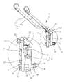
図1は本発明に係る車椅子の車輪ロック装置Bを適用した車椅子Aの斜視図を示し、この車椅子の車輪ロック装置(以下、ロック装置という)Bは、車椅子Aのフレーム1に固定された装置本体2と、車椅子Aの車輪3に固定された円盤4とで構成されている(図2参照)。
FIG. 1 shows a perspective view of a wheelchair A to which a wheel lock device B of a wheelchair according to the present invention is applied. The wheel lock device (hereinafter referred to as a lock device) B of the wheelchair is a device fixed to a
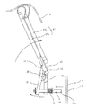
装置本体2はフレーム1に固定された固定部材5を介してフレーム1に固定される支持部材10と、この支持部材10の上端に支軸11で上下に回動可能に支持されるとともに、バネ12で上方に回動するように付勢された回動部材13と、この回動部材13の下面に支軸14を介して垂下して取り付けられた作動部材15と、この作動部材15の下部に取り付けられた制動ピン16とで主に構成されている(図3参照)。
The apparatus
上記回動部材13には座面6の裏面に係合するセンサーアーム17が固定されている。このセンサーアーム17は第1のセンサーアーム17aと第2のセンサーアーム17bとからなり、第1のセンサーアーム17aは座面6の前部に、第2のセンサーアーム22は座面6の中央部に対応するように配置され、利用者が座面6の前部に座っても、座面の中央に座ったときと同じように座面6の動きを感知できるようになっている。
A
上記作動部材15は略U字状に曲折して形成され、上部にはローラ20が取り付けられ、下部には支持部材10を貫通するように配置された制動ピン16の後端16bが支持されている。
The actuating
上記ローラ20は、作動部材15が下降又は上昇すると上記支持部材10に形成された係合部21に係合するようになっている。この係合部21は支持部材10から作動部材15側に向かって斜めに張り出した第1の係合部22と第2の係合部23との2つの係合部で構成され、この第1の係合部22と第2の係合部23とは先端が相反する方向に張り出し、側面視ハの字状に形成されている(図4参照)。
The
上記第1の係合部22は利用者が車椅子に座って座面6が下がり、センサーアーム17が座面6に押し下げられて下方に回動すると(図5参照)、センサーアーム17と一体の回動部材13が下方に回動して作動部材15が下降したときにローラ20が係合する位置に形成されており、上記第2の係合部23は車椅子Aを折り畳んだとき座面6はセンサーアーム17の押圧を解除するので、センサーアーム17はほぼ垂直に近くなるまで上方に回動すると(図6参照)、回動部材13もほぼ垂直に近くなるまで上方に回動し、作動部材15が上昇したときにローラ20が係合する位置に形成されており、ローラ20が第1の係合部22又は第2の係合部23に係合すると作動部材15は支軸14を中心に円盤4から離れる方向に回動させられるようになっている。
When the user sits in a wheelchair and the
上記制動ピン16は、後端16bが作動部材15を貫通し、ワッシャー24を介して固定ピン25が取り付けられ、先端16aは支持部材10のガイド穴10aを貫通して円盤4に突き当たるように配置されている。この制動ピン16は支持部材10の壁面と固定ピン28で位置決めされたワッシャー27との間に配設されたスプリング26で先端16aが円盤4に向かって突出するように付勢され、円盤4に形成された係合孔8に対応すると、先端16aは係合孔8に貫入するようになっている。
The
作動部材15が支持部材10から離反する方向に回動すると、作動部材15の下部に取り付けられた制動ピン16は、図5に示すように円盤から離脱する方向に移動させられるようになっている。
When the actuating
円盤4は車輪3のフレーム1側に、円板7は車輪3の軸部側にそれぞれスポークを挟んで配置され、円盤4に円板7をネジ止めすることにより円盤4を車輪3に固定することができるようになっている。
The
そして、円盤4の周囲には、多数の係合孔8が環状に配置され、この係合孔8の大きさは上述した制動ピン16の先端16aが貫入できる大きさに形成されていればよい。
A large number of
上記構成のロック装置Bによれば、車椅子Aに利用者が座ると図7に示すように、座面6が下がり、バネ12に抗してセンサーアーム17(回動部材13)が支軸11を中心に下方に回動するので、係合板15は下降することになる(図5参照)。係合板15が下降するとローラ20が第1の係合部22に係合し、これに乗り上げるので、作動部材15は支軸14を中心に外側(矢印a方向)に回動して、支持部材10から離れる方向に動くことになるので、制動ピン16はスプリング26に抗して円盤4から離れる方向に移動させられ、制動ピン16の先端16aは、円盤4の係合孔8から抜脱し、円盤4のロックを解除するので車輪3は回転可能になり、利用者は車椅子Aに座った状態で車輪3を動かして移動することができるようになる。
According to the locking device B having the above configuration, when the user sits on the wheelchair A, the
一方、利用者が車椅子Aのシート6から離れるとセンサーアーム17の押し下げが解除されるので、図4に示すように、回動部材13はバネ12に付勢されて上方に回動するが、センサーアーム17は座面6に当接しているのでその回動量は制限される。この状態では、作動部材15は上昇してローラ20と第1の係合部22との係合は外れるが第2の係合部23に係合するまでは上昇しないので、作動部材15は支軸14を中心に反時計方向に回動して下方が支持部材10に接近する方向に動くので、制動ピン16はスプリング26に付勢されて円盤4に当接する方向に移動し、係合孔8に対向した制動ピン16の先端16aは係合孔8に没入する。
On the other hand, when the user leaves the
制動ピン16の先端16aが係合孔8に没入すると円盤4の回転は阻止され、結果として車輪3の回転も阻止され、車輪3はロックされた状態になるので、利用者が車椅子Aから離れようとして腰を浮かせた際には自動的に車輪3がロックされ、車椅子Aが勝手に動き出して利用者が転倒する事故を未然に防止することができる。
When the
しかも、利用状態にない車椅子を収納したり、移動させたりするときには、図8に示すように、折り畳むことにより、座面6は大きく撓んでセンサーアーム17の押圧はなくなるので、センサーアーム17(回動部材13)はバネ12に付勢されてさらに上方に回動し、図6に示すように、作動部材15はさらに上昇してローラ20が第2の係合部23に乗り上げる状態になり、作動部材15は支軸14を中心に外側に回動させられて下方が支持部材10から離れる方向に動くので、制動ピン16はスプリング26に抗して円盤4から離れる方向に強制的に移動させられ、制動ピン16の先端16aは円盤4の係合孔8から抜けて円盤4のロックを解除するので車輪3は回転可能になり、車椅子Aを折り畳むだけでロックを解除する特別な操作をすることなく移動させることができる。
Moreover, when a wheelchair that is not in use is stored or moved, as shown in FIG. 8, the
上述のように、利用者が車椅子の座面6に座るか座らないか、車椅子を折り畳んだか否かで、制動ピン16が円盤4の係合孔8に係合するか否かが自動的に選択され、利用者が意識することなく使用態様に応じて車輪3のロック、ロック解除を自動的に行なうことができる。
As described above, whether or not the
しかも、ワイヤーを用いることなく車輪3のロック、ロック解除が確実に行なわれるので、経年変化でワイヤーが伸び、調整をしなければならない煩わしさも回避することができる。
Moreover, since the
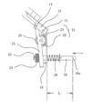
なお、上述の固定ピン25を割りピンで構成し、制動ピン16に着脱できるようにしてもよい。このことによりワッシャー24の枚数を自由に設定することができるので、図9に示すように、ワッシャー24の枚数に応じて制動ピン16の実質的な長さL(支持部材10の前面から制動ピン16の先端16aまでの長さ)を変えることができ、車椅子Aの形状に対応して制動ピン16と円盤4との距離を自由に設定することができ、長さの異なる制動ピン16を用意することなく様々な車椅子Aに対応させることができ、生産の効率を高めることができる。
The fixing
図10は、装置本体2の他の例を示し、この装置本体2は制動ピン16の動きを規制する規制部材30を設けたものである。この規制部材30は平面視コ字状に形成されたフレーム枠31とシャッター31とで構成され、フレーム枠31の両側片の先端は支持部材10に固定され、前面には制動ピン16が出没可能な大きさの穴部33が形成され、この穴部の両側にはシャッター32を保持するガイド軸34と、シャッター32に係合する係合軸35とが設けてある。
FIG. 10 shows another example of the apparatus
シャッター32は略長方形の板部材で、長手方向斜めに長孔36が形成されるとともに前部には係合凹部37が形成され、長孔36がフレーム枠31の前面に設けたガイド軸34に支持されてフレーム枠31の前面をスライド可能に配置され、図11に示すように、一方にスライドさせた時には穴部33を開放し、他方にスライドした時には係合凹部37が係合軸35に係合して水平状態になり穴部33を塞ぐことができるようになっているものである。
The
上述の規制部材30で制動ピン16の動きを規制する場合は、制動ピン16を穴部33から突出しない状態にしてシャッター32で穴部33を閉じることにより、制動ピン16は座面6の状態にかかわらず円盤4から外れているので、車輪3はロック状態が解除され、車椅子に人が座っていない状態でも自由に移動させることができる。
When the movement of the
1 フレーム
2 装置本体
3 車輪
4 円盤
5 固定部材
6 座面
7 円板
8 係合孔
10 支持部材
13 回動部材
15 作動部材
16 制動ピン
17 センサーアーム
20 ローラ
21 係合部
DESCRIPTION OF
Claims (3)
(イ)上記装置本体は、車椅子のフレームに固定される支持部材と、該支持部材に支持され座面の上下に連動して上下に回動する回動部材と、該回動部材の回動に連動して上下動する作動部材とを備えたこと
(ロ)上記作動部材には上記制動ピンと、上記支持部材の所定の位置に設けた係合部に係合するローラとを設けたこと
(ハ)上記座面が下がって上記回動部材が下方に回動すると、上記作動部材が下動して上記ローラが上記係合部に係合したときには、該作動部材は上記円盤から離反する方向に回動させられ、上記制動ピンは上記円盤の係合孔から抜脱すること A disc fixed to the wheel and provided with an annular engagement hole in the periphery, and a device body that engages and disengages the brake pin with the engagement hole of the disc and locks the wheelchair wheel when engaged, A wheel lock device for a wheelchair comprising the following requirements:
(A) The apparatus main body includes a support member fixed to the frame of the wheelchair, a rotation member that is supported by the support member and rotates up and down in conjunction with the vertical movement of the seat surface, and the rotation of the rotation member (B) The actuating member is provided with the brake pin and a roller that engages with an engaging portion provided at a predetermined position of the support member ( C) When the seating surface is lowered and the rotating member is rotated downward, when the operating member is moved downward and the roller is engaged with the engaging portion, the operating member is separated from the disk. The brake pin is removed from the engagement hole of the disk.
Priority Applications (1)
| Application Number | Priority Date | Filing Date | Title |
|---|---|---|---|
| JP2008274268A JP5107864B2 (en) | 2008-10-24 | 2008-10-24 | Wheelchair wheel lock device |
Applications Claiming Priority (1)
| Application Number | Priority Date | Filing Date | Title |
|---|---|---|---|
| JP2008274268A JP5107864B2 (en) | 2008-10-24 | 2008-10-24 | Wheelchair wheel lock device |
Publications (2)
| Publication Number | Publication Date |
|---|---|
| JP2010099314A true JP2010099314A (en) | 2010-05-06 |
| JP5107864B2 JP5107864B2 (en) | 2012-12-26 |
Family
ID=42290489
Family Applications (1)
| Application Number | Title | Priority Date | Filing Date |
|---|---|---|---|
| JP2008274268A Active JP5107864B2 (en) | 2008-10-24 | 2008-10-24 | Wheelchair wheel lock device |
Country Status (1)
| Country | Link |
|---|---|
| JP (1) | JP5107864B2 (en) |
Cited By (5)
| Publication number | Priority date | Publication date | Assignee | Title |
|---|---|---|---|---|
| JP2011024762A (en) * | 2009-07-24 | 2011-02-10 | Biomedical Engineering Inc | Braking device, braking method, and wheelchair |
| JP2012029988A (en) * | 2010-08-02 | 2012-02-16 | Gunji Kk | Wheel lock device for wheelchair |
| JP2012148002A (en) * | 2011-01-20 | 2012-08-09 | Norimichi Kawashima | Braking device, braking method, and wheelchair |
| JP2014076271A (en) * | 2012-09-21 | 2014-05-01 | Oita Univ | Wheelchair with automatic brake |
| JP7127907B1 (en) * | 2021-10-20 | 2022-08-30 | 株式会社 ドリーム・ダブル | Wheelchairs and automatic braking mechanisms for wheelchairs |
Citations (5)
| Publication number | Priority date | Publication date | Assignee | Title |
|---|---|---|---|---|
| JPH1085267A (en) * | 1996-09-20 | 1998-04-07 | Kazuo Kubo | Wheelchair and automatic brake device for wheelchair |
| JPH10151167A (en) * | 1996-11-21 | 1998-06-09 | Nippon Medics:Kk | Separated wheelchair type bathing device |
| JP2003153961A (en) * | 2001-11-20 | 2003-05-27 | Noritaka Kimura | Wheelchair with automatic brake |
| JP2005516733A (en) * | 2002-02-11 | 2005-06-09 | ストライカー カナダ エルピー | wheelchair |
| JP2007307348A (en) * | 2005-10-31 | 2007-11-29 | Gunji Kk | Wheel lock device for wheelchair |
-
2008
- 2008-10-24 JP JP2008274268A patent/JP5107864B2/en active Active
Patent Citations (5)
| Publication number | Priority date | Publication date | Assignee | Title |
|---|---|---|---|---|
| JPH1085267A (en) * | 1996-09-20 | 1998-04-07 | Kazuo Kubo | Wheelchair and automatic brake device for wheelchair |
| JPH10151167A (en) * | 1996-11-21 | 1998-06-09 | Nippon Medics:Kk | Separated wheelchair type bathing device |
| JP2003153961A (en) * | 2001-11-20 | 2003-05-27 | Noritaka Kimura | Wheelchair with automatic brake |
| JP2005516733A (en) * | 2002-02-11 | 2005-06-09 | ストライカー カナダ エルピー | wheelchair |
| JP2007307348A (en) * | 2005-10-31 | 2007-11-29 | Gunji Kk | Wheel lock device for wheelchair |
Cited By (5)
| Publication number | Priority date | Publication date | Assignee | Title |
|---|---|---|---|---|
| JP2011024762A (en) * | 2009-07-24 | 2011-02-10 | Biomedical Engineering Inc | Braking device, braking method, and wheelchair |
| JP2012029988A (en) * | 2010-08-02 | 2012-02-16 | Gunji Kk | Wheel lock device for wheelchair |
| JP2012148002A (en) * | 2011-01-20 | 2012-08-09 | Norimichi Kawashima | Braking device, braking method, and wheelchair |
| JP2014076271A (en) * | 2012-09-21 | 2014-05-01 | Oita Univ | Wheelchair with automatic brake |
| JP7127907B1 (en) * | 2021-10-20 | 2022-08-30 | 株式会社 ドリーム・ダブル | Wheelchairs and automatic braking mechanisms for wheelchairs |
Also Published As
| Publication number | Publication date |
|---|---|
| JP5107864B2 (en) | 2012-12-26 |
Similar Documents
| Publication | Publication Date | Title |
|---|---|---|
| JP5107864B2 (en) | Wheelchair wheel lock device | |
| CA2881133C (en) | Child safety seat | |
| JP2010006371A (en) | Child safety seat | |
| US9173529B2 (en) | Bath chair | |
| JP4887099B2 (en) | Wheelchair wheel lock device | |
| JP2006281814A (en) | Seat slide device having walk-in locking mechanism with memory | |
| JP5356678B2 (en) | Mobile desk | |
| JP2009270550A (en) | Attaching/detaching device of impeller | |
| EP3437919B1 (en) | A safety chair comprising an anti-return mechanism | |
| JP6174315B2 (en) | Child seat for vehicle seat | |
| CN104742765A (en) | Child safety seat | |
| JP5651816B2 (en) | Rotating mechanism in bed grip | |
| JP5499394B2 (en) | Lock mechanism for moving bars | |
| JP4103048B2 (en) | Caster lock operating device | |
| KR101988744B1 (en) | Vehicle-mounted Armrest device | |
| JP2007015599A (en) | Seat device | |
| JP5567931B2 (en) | Wheelchair wheel lock device | |
| KR200386199Y1 (en) | Safety belt buckle | |
| JP5444688B2 (en) | Press machine | |
| JP3771376B2 (en) | Desorption seat | |
| JP2010252885A (en) | Seat reclining device | |
| JP2006240534A (en) | Reclining device | |
| JP2010195376A (en) | Slide rail device for vehicle | |
| JP2010195377A (en) | Slide rail device for vehicle | |
| CA2651526A1 (en) | Printing roll release of the head in the thermal printer |
Legal Events
| Date | Code | Title | Description |
|---|---|---|---|
| A621 | Written request for application examination |
Free format text: JAPANESE INTERMEDIATE CODE: A621 Effective date: 20100622 |
|
| A977 | Report on retrieval |
Free format text: JAPANESE INTERMEDIATE CODE: A971007 Effective date: 20120330 |
|
| A131 | Notification of reasons for refusal |
Free format text: JAPANESE INTERMEDIATE CODE: A131 Effective date: 20120417 |
|
| A521 | Written amendment |
Free format text: JAPANESE INTERMEDIATE CODE: A523 Effective date: 20120614 |
|
| TRDD | Decision of grant or rejection written | ||
| A01 | Written decision to grant a patent or to grant a registration (utility model) |
Free format text: JAPANESE INTERMEDIATE CODE: A01 Effective date: 20120925 |
|
| A01 | Written decision to grant a patent or to grant a registration (utility model) |
Free format text: JAPANESE INTERMEDIATE CODE: A01 |
|
| A61 | First payment of annual fees (during grant procedure) |
Free format text: JAPANESE INTERMEDIATE CODE: A61 Effective date: 20121004 |
|
| R150 | Certificate of patent or registration of utility model |
Ref document number: 5107864 Country of ref document: JP Free format text: JAPANESE INTERMEDIATE CODE: R150 Free format text: JAPANESE INTERMEDIATE CODE: R150 |
|
| FPAY | Renewal fee payment (event date is renewal date of database) |
Free format text: PAYMENT UNTIL: 20151012 Year of fee payment: 3 |
|
| R250 | Receipt of annual fees |
Free format text: JAPANESE INTERMEDIATE CODE: R250 |
|
| R250 | Receipt of annual fees |
Free format text: JAPANESE INTERMEDIATE CODE: R250 |
|
| R250 | Receipt of annual fees |
Free format text: JAPANESE INTERMEDIATE CODE: R250 |
|
| R250 | Receipt of annual fees |
Free format text: JAPANESE INTERMEDIATE CODE: R250 |
|
| R250 | Receipt of annual fees |
Free format text: JAPANESE INTERMEDIATE CODE: R250 |
|
| R250 | Receipt of annual fees |
Free format text: JAPANESE INTERMEDIATE CODE: R250 |
|
| S111 | Request for change of ownership or part of ownership |
Free format text: JAPANESE INTERMEDIATE CODE: R313113 |
|
| R350 | Written notification of registration of transfer |
Free format text: JAPANESE INTERMEDIATE CODE: R350 |
|
| R250 | Receipt of annual fees |
Free format text: JAPANESE INTERMEDIATE CODE: R250 |