JP2010097417A - Message management system, monitored device, monitoring device, message management method and program therefor - Google Patents
Message management system, monitored device, monitoring device, message management method and program therefor Download PDFInfo
- Publication number
- JP2010097417A JP2010097417A JP2008267757A JP2008267757A JP2010097417A JP 2010097417 A JP2010097417 A JP 2010097417A JP 2008267757 A JP2008267757 A JP 2008267757A JP 2008267757 A JP2008267757 A JP 2008267757A JP 2010097417 A JP2010097417 A JP 2010097417A
- Authority
- JP
- Japan
- Prior art keywords
- message
- identifier
- monitoring
- content
- monitoring target
- Prior art date
- Legal status (The legal status is an assumption and is not a legal conclusion. Google has not performed a legal analysis and makes no representation as to the accuracy of the status listed.)
- Granted
Links
Images


Abstract
Description
本発明はコンピュータシステムの運用管理に関し、特に障害情報などのようなメッセージの処理に関する。 The present invention relates to operation management of a computer system, and more particularly to processing of messages such as failure information.
コンピュータシステムの大規模化、複雑化に伴い、システムを維持するために必要な管理コストも増大している。具体的には、同一のネットワークに属するコンピュータの台数の増加、および1台のコンピュータに対して監視しなければならない内容の複雑化などの問題が発生している。 As computer systems become larger and more complex, the management costs required to maintain the systems are also increasing. Specifically, problems such as an increase in the number of computers belonging to the same network and complication of contents to be monitored for one computer have occurred.
そのため、コンピュータネットワークの中に、同一のネットワークに属する他のコンピュータの動作状況を監視する専用の装置を設けることがある。ここでは、そのような装置を監視装置といい、監視装置が監視する対象となるコンピュータ装置を監視対象装置という。監視対象装置は、自らの動作状況を表すメッセージを、ネットワークを介して監視装置に送付する。監視装置は、これらのメッセージを収集して表示する。監視装置と監視対象装置とが同一のネットワークに接続されてなるシステムを、ここではメッセージ管理システムという。 Therefore, a dedicated device for monitoring the operation status of other computers belonging to the same network may be provided in the computer network. Here, such a device is called a monitoring device, and a computer device to be monitored by the monitoring device is called a monitoring target device. The monitoring target device sends a message indicating its own operation status to the monitoring device via the network. The monitoring device collects and displays these messages. A system in which the monitoring device and the monitoring target device are connected to the same network is referred to as a message management system here.
このようなメッセージ管理システムに関連する技術文献として、次のものが開示されている。特許文献1には、監視対象装置から受信したメッセージを置換・フィルタリングして表示する監視装置が記載されている。特許文献2には、メッセージを所定のルールで抽出してカウントし、このカウントされた値によって発生頻度を抽出する監視装置が記載されている。特許文献3には、メッセージを保持手段内に保持し、特定のルールに従って古いメッセージを保持手段から削除して処理効率を向上させるという監視装置が記載されている。
The following is disclosed as technical literature related to such a message management system.
また、メッセージ管理システム以外でメッセージ交換を効率化する技術として、特許文献4には、通信装置のメッセージシーケンスパターンの中を学習して、何度も出てくるパターンを置換するという技術が記載されている。特許文献5には、プログラムのソースコードを特定の識別子で置換するという技術が記載されている。 Further, as a technique for improving the efficiency of message exchange other than the message management system, Patent Document 4 describes a technique of learning a message sequence pattern of a communication device and replacing a pattern that appears many times. ing. Patent Document 5 describes a technique of replacing a program source code with a specific identifier.
前述のようなコンピュータシステムの大規模化および複雑化に伴い、監視装置が検知しなければならない監視対象装置の動作状態を通知するメッセージの量も増加の一途をたどっている。それによって、監視装置と監視対象装置の間のネットワークの負荷や、メッセージを集約して抽出処理を行う監視装置上での負荷が増大している。そのため、監視対象装置から発生するメッセージ量の削減、および監視装置上での処理の効率化が求められている。 Along with the increase in scale and complexity of the computer system as described above, the amount of messages that notify the operation state of the monitoring target device that must be detected by the monitoring device continues to increase. As a result, the load on the network between the monitoring apparatus and the monitoring target apparatus and the load on the monitoring apparatus that collects messages and performs extraction processing are increasing. Therefore, there is a demand for reduction in the amount of messages generated from the monitoring target device and efficient processing on the monitoring device.
特許文献1〜3の技術はいずれも、監視対象装置から監視装置に収集された後のメッセージに対する処理についてのものである。そのため、監視装置と監視対象装置の間のネットワークの負荷の軽減にはなっていない。また特許文献3の技術は、メッセージを保持手段内に保持し、特定のルールに従って古いメッセージを保持手段から削除しているので、監視対象装置をリアルタイムに監視できず、さらに削除された後のメッセージに対応する管理を行うことができない。
The techniques of
さらに、特許文献4〜5の技術はいずれも、特定の装置内部の処理であり、装置と装置の間のネットワークの負荷を軽減するものではない。また同文献でいうメッセージの質も、本発明が問題としているメッセージ管理システムにおけるそれとは異なるので、監視装置と監視対象装置の間でメッセージ交換を効率化してネットワークの負荷を軽減する目的に適用することができない。 Furthermore, all of the techniques of Patent Documents 4 to 5 are processing inside a specific device, and do not reduce the load on the network between the devices. The message quality in this document is also different from that in the message management system in which the present invention is a problem. Therefore, the message quality is applied to the purpose of improving the efficiency of message exchange between the monitoring device and the monitoring target device and reducing the load on the network. I can't.
本発明の目的は、監視装置と監視対象装置の間のネットワークの負荷を軽減し、監視対象装置をリアルタイムに監視することを可能とするメッセージ管理システム、監視対象装置、監視装置、メッセージ管理方法およびそのプログラムを提供することにある。 An object of the present invention is to provide a message management system, a monitoring target device, a monitoring device, a message management method, and a message management system capable of reducing a network load between the monitoring device and the monitoring target device and monitoring the monitoring target device in real time. To provide that program.
上記目的を達成するため、本発明に係るメッセージ管理システムは、1台もしくは複数台のコンピュータ装置である監視対象装置と、監視対象装置の動作状態を監視する監視装置とが相互に接続されてなるメッセージ管理システムであって、監視対象装置が、自らの動作状況を示すメッセージ内容を含む第1のメッセージを生成するメッセージ生成部と、メッセージ内容と識別子との対応をあらかじめ記憶した第1の解析テーブルと、メッセージ内容を識別子に置換して第2のメッセージを生成するメッセージ変換部と、第2のメッセージを監視装置に送信するメッセージ送信部とを有し、監視装置が、第2のメッセージを監視対象装置から受信するメッセージ受信部と、第1の解析テーブルと同一の内容をあらかじめ記憶した第2の解析テーブルと、第2の解析テーブルに記憶された内容に基づいて識別子をメッセージ内容に置換して第1のメッセージを復元するメッセージ復元部と、復元された第1のメッセージを表示するメッセージ表示部とを有することを特徴とする。 In order to achieve the above object, a message management system according to the present invention includes a monitoring target device that is one or a plurality of computer devices and a monitoring device that monitors the operating state of the monitoring target device. A message management system, in which a monitoring target device generates a first message including a message content indicating its own operation status, and a first analysis table that stores in advance the correspondence between the message content and an identifier A message conversion unit that generates a second message by replacing the message content with an identifier, and a message transmission unit that transmits the second message to the monitoring device. The monitoring device monitors the second message. A message receiving unit that receives from the target device, and a second analysis table that stores in advance the same contents as the first analysis table. A message restoring unit that restores the first message by replacing the identifier with the message content based on the content stored in the second analysis table, and a message display unit that displays the restored first message It is characterized by having.
上記目的を達成するため、本発明に係る監視対象装置は、動作状態を監視する監視装置と相互に接続された監視対象装置であって、自らの動作状況を示すメッセージ内容を含む第1のメッセージを生成するメッセージ生成部と、メッセージ内容と識別子との対応をあらかじめ記憶した解析テーブルと、メッセージ内容を識別子に置換して第2のメッセージを生成するメッセージ変換部と、第2のメッセージを監視装置に送信するメッセージ送信部とを有することを特徴とする。 In order to achieve the above object, a monitoring target device according to the present invention is a monitoring target device interconnected with a monitoring device that monitors an operation state, and includes a first message including a message content indicating its own operation status. A message generation unit that generates a message, an analysis table that stores correspondence between the message content and the identifier in advance, a message conversion unit that generates a second message by replacing the message content with the identifier, and a monitoring device for the second message And a message transmission unit that transmits the message.
上記目的を達成するため、本発明に係る監視装置は、1台もしくは複数台のコンピュータ装置である監視対象装置と相互に接続され、監視対象装置の動作状態を監視する監視装置であって、識別子を含むメッセージを監視対象装置から受信するメッセージ受信部と、メッセージ内容と識別子との対応をあらかじめ記憶した解析テーブルと、メッセージに識別子が含まれている場合に、解析テーブルに記憶された内容に基づいて識別子をメッセージ内容に置換してメッセージを復元するメッセージ復元部と、復元されたメッセージを表示するメッセージ表示部とを有することを特徴とする。 In order to achieve the above object, a monitoring apparatus according to the present invention is a monitoring apparatus that is interconnected with a monitoring target apparatus that is one or a plurality of computer apparatuses, and that monitors the operating state of the monitoring target apparatus. Based on the contents stored in the analysis table when the message includes an identifier, the message reception unit that receives the message including the message from the monitoring target device, the analysis table that stores the correspondence between the message content and the identifier in advance And a message restoration unit for restoring the message by replacing the identifier with the message content, and a message display unit for displaying the restored message.
上記目的を達成するため、本発明に係るメッセージ管理方法は、1台もしくは複数台のコンピュータ装置である監視対象装置と監視装置とが相互に接続されてなるメッセージ管理システムで、監視対象装置の動作状態を監視するメッセージ管理方法であって、監視対象装置が、自らの動作状況を示すメッセージ内容を含む第1のメッセージを生成し、メッセージ内容と識別子との対応をあらかじめ記憶した第1の解析テーブルを参照して、メッセージ内容を識別子に置換して第2のメッセージを生成し、第2のメッセージを監視装置に送信し、監視装置が、第2のメッセージを監視対象装置から受信し、第1の解析テーブルと同一の内容をあらかじめ記憶した第2の解析テーブルを参照して、第2の解析テーブルに記憶された内容に基づいて識別子をメッセージ内容に置換して第1のメッセージを復元し、復元された第1のメッセージを表示することを特徴とする。 In order to achieve the above object, a message management method according to the present invention is a message management system in which a monitoring target device and a monitoring device, which are one or a plurality of computer devices, are connected to each other. A message management method for monitoring a state, in which a monitoring target device generates a first message including a message content indicating its operation status, and stores a correspondence between the message content and an identifier in advance. The message content is replaced with an identifier to generate a second message, the second message is transmitted to the monitoring device, the monitoring device receives the second message from the monitoring target device, and the first message Based on the contents stored in the second analysis table with reference to the second analysis table in which the same contents as the analysis table of FIG. The first message was restored by replacing the Besshi the message content, and displaying a first message reconstructed.
上記目的を達成するため、本発明に係るメッセージ管理プログラムは、1台もしくは複数台のコンピュータ装置である監視対象装置と、監視対象装置の動作状態を監視する監視装置とが相互に接続されてなるメッセージ管理システムにあって、監視対象装置があらかじめ備えるコンピュータに、自らの動作状況を示すメッセージ内容を含む第1のメッセージを生成する手順と、メッセージ内容と識別子との対応をあらかじめ記憶した解析テーブルを参照する手順と、メッセージ内容を識別子に置換して第2のメッセージを生成する手順と、生成された第2のメッセージを監視装置に送信する手順とを実行させることを特徴とする。 In order to achieve the above object, a message management program according to the present invention comprises a monitoring target device, which is one or a plurality of computer devices, and a monitoring device that monitors the operating state of the monitoring target device. In the message management system, an analysis table storing in advance a procedure for generating a first message including a message content indicating its own operation status and a correspondence between the message content and an identifier in a computer provided in advance in the monitoring target device It is characterized in that a reference procedure, a procedure for generating a second message by replacing the message content with an identifier, and a procedure for transmitting the generated second message to a monitoring device are executed.
上記目的を達成するため、本発明に係る別のメッセージ管理プログラムは、1台もしくは複数台のコンピュータ装置である監視対象装置と、監視対象装置の動作状態を監視する監視装置とが相互に接続されてなるメッセージ管理システムにあって、監視装置があらかじめ備えるコンピュータに、識別子を含むメッセージを監視対象装置から受信する手順と、メッセージ内容と識別子との対応をあらかじめ記憶した解析テーブルを参照する手順と、解析テーブルに記憶された内容に基づいて識別子をメッセージ内容に置換してメッセージを復元する手順と、復元されたメッセージを表示する手順とを実行させることを特徴とする。 In order to achieve the above object, another message management program according to the present invention includes a monitoring target device that is one or a plurality of computer devices and a monitoring device that monitors the operating state of the monitoring target device. A procedure for receiving a message including an identifier from a monitoring target device, a procedure for referring to an analysis table in which a correspondence between a message content and an identifier is stored in advance, A procedure for restoring the message by replacing the identifier with the message content based on the content stored in the analysis table and a procedure for displaying the restored message are executed.
本発明は、上述したように監視対象装置がメッセージ内容を識別子に置換して送信し、これを監視装置が受信してから復元するように構成したので、ネットワークを介して送信されるメッセージのデータ量を削減することができる。これによって、監視装置と監視対象装置の間のネットワークの負荷が軽減され、監視対象装置をリアルタイムに監視することが可能となるという、従来にない優れたメッセージ管理システム、監視対象装置、監視装置、メッセージ管理方法およびそのプログラムを提供することができる。 In the present invention, as described above, the monitoring target device replaces the message content with the identifier and transmits it, and the monitoring device receives the message and restores it. The amount can be reduced. Thereby, the load on the network between the monitoring device and the monitoring target device is reduced, and it becomes possible to monitor the monitoring target device in real time, an unprecedented superior message management system, monitoring target device, monitoring device, A message management method and its program can be provided.
(第1の実施形態)
以下、本発明の第1の実施形態の構成について添付図1に基づいて説明する。
最初に、本実施形態の基本的な内容について説明し、その後でより具体的な内容について説明する。
第1の実施形態に係るメッセージ管理システム1は、1台もしくは複数台のコンピュータ装置である監視対象装置10と、監視対象装置の動作状態を監視する監視装置20とが相互に接続されてなる。監視対象装置10は、自らの動作状況を示すメッセージ内容を含む第1のメッセージを生成するメッセージ生成部32と、メッセージ内容と識別子との対応をあらかじめ記憶した第1の解析テーブル36と、メッセージ内容を識別子に置換して第2のメッセージを生成するメッセージ変換部34と、第2のメッセージを監視装置に送信するメッセージ送信部35とを有し、監視装置20は、第2のメッセージを監視対象装置から受信するメッセージ受信部41と、第1の解析テーブルと同一の内容をあらかじめ記憶した第2の解析テーブル45と、第2の解析テーブルに記憶された内容に基づいて識別子をメッセージ内容に置換して第1のメッセージを復元するメッセージ復元部43と、復元された第1のメッセージを表示するメッセージ表示部44とを有する。
(First embodiment)
Hereinafter, the structure of the 1st Embodiment of this invention is demonstrated based on attached FIG.
First, the basic content of the present embodiment will be described, and then more specific content will be described.
The
ここで、監視対象装置10は、第1の解析テーブル36にメッセージ内容に対応する識別子が記憶されていない場合に新たな識別子を発行する第1のメッセージ解析部33を有し、監視対象装置10はさらにメッセージ解析部34がメッセージ内容と新たな識別子とを含む第3のメッセージを生成すると共に、メッセージ送信部35がこの生成された第3のメッセージを監視装置20に送信する。監視装置20は、メッセージ受信部41が第3のメッセージを受信したことに反応して、メッセージ内容と新たな識別子とを第2の解析テーブル45に記憶する第2のメッセージ解析部42を有する。
Here, the
この構成を備えることにより、本実施形態は、送信されるメッセージのデータ量を削減し、監視装置と監視対象装置の間のネットワークの負荷を軽減することを可能とする。
以下、これをより詳細に説明する。
With this configuration, the present embodiment can reduce the data amount of the message to be transmitted and reduce the network load between the monitoring device and the monitoring target device.
Hereinafter, this will be described in more detail.
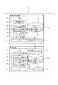
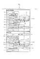
図1は、本発明の第1の実施形態に係るメッセージ管理システム1の構成を示す説明図である。メッセージ管理システム1は、監視対象装置10と、監視対象装置10からのメッセージを収集する監視装置20とから構成されている。監視対象装置10と監視装置20はいずれもコンピュータ装置であり、LAN(Local Area Network)などによって相互に接続されている。図1では監視対象装置10と監視装置20とを各1台ずつ示しているが、実際には複数台の監視対象装置10を1台の監視装置20によって監視する場合もある。
FIG. 1 is an explanatory diagram showing the configuration of the
監視対象装置10は、プログラムを実行する主体であるCPU11(Central Processing Unit)と、CPU11で実行中のプログラムを記憶するRAM12(Random Access Memory)、不揮発性記憶装置であるHDD13(Hard Disk Drive)、および監視装置20とのデータ通信を行う通信インターフェイス14とを備える。
The
そしてRAM12に、自身の現在の動作状況を取得する情報取得部31と、取得された動作状況に基づいてメッセージを生成するメッセージ生成部32と、メッセージの解析を行う第1のメッセージ解析部33と、解析結果を元にメッセージの変換を行うメッセージ解析部34と、監視装置20にメッセージを送付するメッセージ送信部35とが記憶される。これらはいずれも、CPU11によって実行されるコンピュータプログラムとして実現される。そして、HDD13には第1の解析テーブル36がデータとして記憶される。
In the
情報取得部31は、監視対象装置10の現在の動作状況について、情報の取得をおこなう。メッセージ生成部32は、情報取得部31が取得した情報を元にメッセージを生成する。第1のメッセージ解析部33は、第1の解析テーブル36に記録された情報を元に、メッセージ生成部32が生成したメッセージを解析する。メッセージ解析部34は、第1のメッセージ解析部33が解析した内容と、第1の解析テーブル36に記録された情報を元にメッセージの変換を行う。
The
メッセージ送信部35は、メッセージ解析部34が変換したメッセージを、通信インターフェイス14を介して監視装置20に送付する。第1の解析テーブル36は、第1のメッセージ解析部33の解析結果により、メッセージ解析部34が後に示すメッセージの変換を行うために使用されるデータが保存される。
The
監視装置20も監視対象装置10と同様に、プログラムを実行する主体であるCPU21と、CPU21で実行中のプログラムを記憶するRAM22、不揮発性記憶装置であるHDD23、監視対象装置10とのデータ通信を行う通信インターフェイス24、およびディスプレイ25を備える。
Similarly to the
そしてRAM22に、監視対象装置からのメッセージを受け取るメッセージ受信部41と、受信したメッセージの解析を行う第2のメッセージ解析部42と、メッセージの復元を行うメッセージ復元部43と、復元されたメッセージをディスプレイ25に表示するメッセージ表示部44とが記憶される。これらはいずれも、CPU21によって実行されるコンピュータプログラムとして実現される。そして、HDD23には第2の解析テーブル45がデータとして記憶される。
The
メッセージ受信部41は、通信インターフェイス24を介して監視対象装置10からのメッセージを受け取る。第2のメッセージ解析部42は、第2の解析テーブル45に記録された内容を元に、メッセージ受信部41が受信したメッセージを解析する。メッセージ復元部43は、第2のメッセージ解析部42が解析した内容と、第2の解析テーブル45に記録された情報を元にメッセージの復元を行う。
The
メッセージ表示部44は、メッセージ復元部43が復元したメッセージをディスプレイ25に表示する。第2の解析テーブル45は、監視対象装置10側の第1の解析テーブル36と同内容が記録される。
The
図2は、図1に示したメッセージ管理システム1の動作を示すフローチャートである。情報取得部31は、監視対象装置10の性能情報やログ情報といった監視項目を常時監視している。情報取得部31が何らかのイベントの発生を検出した場合、メッセージ生成部32は該イベントに対応するメッセージを生成する(ステップS100)。第1のメッセージ解析部33は、この生成されたメッセージの内容を解析し(ステップS101)、既に第1の解析テーブル36に記録されているものと一致するかどうかの判定を行う(ステップS102)。
FIG. 2 is a flowchart showing the operation of the
生成されたメッセージが第1の解析テーブル36に登録されていないメッセージであった場合(ステップS102:NO)、第1のメッセージ解析部33は、このメッセージの内容に対して第1の解析テーブル36に登録されていない識別子を新規に発行し、解析結果記録部に識別子とメッセージの内容とを関連付けて登録する(ステップS103B)。また、メッセージ解析部34は、このメッセージと、新たに付与された識別子とを、メッセージ送信部35を介して監視装置20に送付する(ステップS104B)。
When the generated message is a message that is not registered in the first analysis table 36 (step S102: NO), the first
監視装置20では、メッセージ受信部41によってメッセージを受信し、第2のメッセージ解析部42により、受信したメッセージにメッセージ内容と識別子が含まれていることを解析し(ステップS105B)、このメッセージ内容と識別子の対応を第2の解析テーブル45に登録する(ステップS106B)。その後、メッセージ表示部44により、オペレータに対して該メッセージの表示を行う(ステップS107)。
In the monitoring device 20, the message is received by the
ステップS102で、第1の解析テーブル36に登録されているメッセージであった場合は(ステップS102:YES)、メッセージ内容を第1の解析テーブル36に登録されている識別子に変換し(ステップS103A)、変換したメッセージをメッセージ送信部35を介して監視装置20に送付する(ステップS104A)。 If the message is registered in the first analysis table 36 in step S102 (step S102: YES), the message content is converted into an identifier registered in the first analysis table 36 (step S103A). The converted message is sent to the monitoring apparatus 20 via the message transmission unit 35 (step S104A).
監視装置20では、メッセージ受信部41によってメッセージを受信し、第2のメッセージ解析部42により、受信したメッセージが識別子に変換されたものである事を解析し(ステップS105A)、その識別子を元に、第2の解析テーブル45から対応したメッセージ内容を取得し、メッセージの復元を行う(ステップS106A)。その後、メッセージ表示部44が、該メッセージをディスプレイ25に表示する(ステップS107)。
In the monitoring device 20, the message is received by the
(動作の一例)
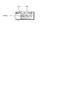
図3は、図1に示すメッセージ生成部32によって生成されたメッセージ300の一例を示す説明図である。メッセージ300は、固定部301とメッセージ内容302とで構成される。固定部301は、日時など、メッセージごとに変わる可能性が高い内容を示すものであり、あらかじめ第1のメッセージ解析部33及びメッセージ解析部34に対してこれに該当する内容を固定部として登録しておく。
(Example of operation)
FIG. 3 is an explanatory diagram showing an example of the
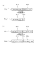
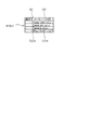
また図4は、図1に示す第1の解析テーブル36のデータ構成の一例を示す説明図である。第1の解析テーブル36は、メッセージ内容302と識別子401とを関連づけて記憶している。後述する監視装置20側の第2の解析テーブル45も、この第1の解析テーブル36と同一のデータ構成およびデータ内容を有する。図4で示した例では、識別子401は「1」「2」「3」…といった数字を利用したが、実際には識別子401は任意の文字や記号などを利用することができる。そして図5は、ステップS103AおよびS103Bに示したメッセージ解析部34による処理で、メッセージ300から変換された変換後メッセージ500の一例を示す説明図である。
FIG. 4 is an explanatory diagram showing an example of the data structure of the first analysis table 36 shown in FIG. The first analysis table 36
第1のメッセージ解析部33はメッセージ300に対して、ステップS102でメッセージ内容302の解析を行う。図3に示すメッセージ300の1行目で、メッセージ内容302a「aaaa was cccc」は、図4に示す第1の解析テーブル36の1行目と一致するので、メッセージ解析部34はステップS103Aでこれを識別子「1」に置換し(図5(a)では置換後識別子502aで示す)、固定部301aはそのままにしてステップS104Aで監視装置20に送付する。
The first
図5(a)は、メッセージ解析部34により上述の処理を行われた変換後メッセージ500aについて示している。変換後メッセージ500aは、変換されていない固定部301aと、「1」を示す置換後識別子502aとで構成されている。
FIG. 5A shows a
この変換後メッセージ500aを受け取った監視装置20は、第2のメッセージ解析部42によりステップS105Aでこれを解析するが、ここで使用される第2の解析テーブル45には、図4として示した第1の解析テーブル36と同内容が記録されているので、第2のメッセージ解析部42はステップS106Aでこの識別子「1」が示すメッセージ内容を「aaaa was cccc」に置換して、図3に示した元のメッセージ300aを復元することができる。これをメッセージ表示部44が、ステップS107でディスプレイ25に表示する。
The monitoring device 20 that has received the
一方、図3の4行目に示すメッセージ300dのメッセージ内容302d「xxxx host1 zzzz」は、図4に示す第1の解析テーブル36と一致する行はない。そこでメッセージ解析部34は新たな識別子「4」を発行し、ステップS103Bでこれを第1の解析テーブル36に登録する。
On the other hand, the
そしてメッセージ解析部34はステップS104Bで、メッセージ300dを変換した変換後メッセージ500dを監視装置20に送付する。変換後メッセージ500dは、固定部301aとメッセージ内容302dは変換されずそのままだが、固定部301dとメッセージ内容302dの間に発行された新たな識別子503d(この場合は「4」)が付け加えられる。図5(b)は、メッセージ解析部34により上述の処理を行われた変換後メッセージ500dについて示している。変換後メッセージ500dは、図5(b)で示した形以外でも、たとえば固定部301dとメッセージ内容302dの後に新たな識別子503dが付く形でもよい。
In step S104B, the
この変換後メッセージ500dを受け取った監視装置20は、第2のメッセージ解析部42によりステップS105Bでこれを解析するが、ここで使用される第2の解析テーブル45には、この新たな識別子503dは登録されていない。そこで第2のメッセージ解析部42はステップS106Bで、新たな識別子503dとそれに対応するメッセージ内容302dと(この場合はそれぞれ「4」と「xxxx host1 zzzz」)を新たに第2の解析テーブル45に登録する。そして変換後メッセージ500dから新たな識別子503dを取り除いて元のメッセージ300dに戻し、これをメッセージ表示部44がステップS107でディスプレイ25に表示する。
The monitoring device 20 that has received the
図6は、上述の処理によって新たな識別子503dとそれに対応するメッセージ内容302dとが登録された後の第1の解析テーブル36および45について示す説明図である。監視対象装置10の側で新たなメッセージ内容に対応して発行された識別子は、第1の解析テーブル36に記録されると同時に、同じ内容が監視装置20に送られ、第2の解析テーブル45に記録される。従って、第1の解析テーブル36および45は同一の内容が記録されることになる。
FIG. 6 is an explanatory diagram showing the first analysis tables 36 and 45 after the
(第1の実施形態の全体的な動作)
次に、上記の第1の実施形態の全体的な動作について説明する。本実施形態に係る動作は、1台もしくは複数台のコンピュータ装置である監視対象装置10と監視装置20とが相互に接続されてなるメッセージ管理システム1で、監視対象装置10の動作状態を監視するメッセージ管理方法であって、監視対象装置10が、自らの動作状況を示すメッセージ内容を含む第1のメッセージを生成し(図2:ステップS100)、メッセージ内容と識別子との対応をあらかじめ記憶した第1の解析テーブルを参照して、メッセージ内容に対応する識別子が第1の解析テーブルに記憶されている場合に、メッセージ内容を識別子に置換して第2のメッセージを生成し(図2:ステップS102〜103A)、第2のメッセージを監視装置に送信し(図2:ステップS104A)、監視装置20が、第2のメッセージを監視対象装置から受信し(図2:ステップS105A)、第1の解析テーブルと同一の内容が記憶されている第2の解析テーブルを参照して、第2のメッセージに識別子が含まれている場合に、第2の解析テーブルに記憶された内容に基づいて識別子をメッセージ内容に置換して第1のメッセージを復元し(図2:ステップS106A)、復元された第1のメッセージを表示する(図2:ステップS107)。
(Overall operation of the first embodiment)
Next, the overall operation of the first embodiment will be described. The operation according to the present embodiment is a
監視対象装置10があらかじめ備える第1のメッセージ解析部は、第1の解析テーブルにメッセージ内容に対応する識別子が記憶されていない場合には新たな識別子を発行し、続いてメッセージ内容と新たな識別子とを含む第3のメッセージを生成し(図2:ステップS102〜103B)、これに続いて監視対象装置10が第3のメッセージを監視装置に送信し(図2:ステップS104B)、監視装置20が、第3のメッセージを受信したことに反応して、メッセージ内容と新たな識別子とを第2の解析テーブルに記憶する(図2:ステップS105B〜106B)。
The first message analysis unit provided in advance in the
ここで、上記各動作ステップについては、これをコンピュータで実行可能にプログラム化し、これらを前記各ステップを直接実行するコンピュータである監視対象装置10および監視装置20に実行させるようにしてもよい。
この動作により、本実施形態は以下のような効果を奏する。
Here, each of the above operation steps may be programmed to be executable by a computer, and may be executed by the
By this operation, this embodiment has the following effects.
本実施の形態では、既出のメッセージが生成された場合は、そのメッセージ内容に対応する識別子のみが送付されるように構成されているため、監視対象装置と監視装置との間で交換されるメッセージのデータ量を削減し、効率的にメッセージの送受信を行える。 In the present embodiment, when an existing message is generated, only an identifier corresponding to the message content is sent, so a message exchanged between the monitoring target device and the monitoring device The amount of data can be reduced and messages can be sent and received efficiently.
本実施の形態ではさらに、初出のメッセージが生成された場合は、そのメッセージを送付する際に、メッセージ内容に対応する識別子を合わせて送付するように構成されているため、監視対象装置と監視装置との間でメッセージ内容とそれに対応する識別子を効率的に共有できる。 Further, in the present embodiment, when the first message is generated, when the message is sent, the identifier corresponding to the message content is sent together, so that the monitoring target device and the monitoring device Can efficiently share message contents and identifiers corresponding to them.
また、本実施の形態では、発生したメッセージをバッファリングすることなく、リアルタイムにディスプレイ25に表示することができる。このため、監視対象装置の動作状態の監視を、リアルタイム性を失わずに行うことができる。
Moreover, in this Embodiment, the message which generate | occur | produced can be displayed on the
(第2の実施形態)
以下、本発明の第2の実施形態の構成について添付図1に基づいて説明する。
最初に、本実施形態の基本的な内容について説明し、その後でより具体的な内容について説明する。
(Second Embodiment)
Hereinafter, the configuration of the second embodiment of the present invention will be described with reference to FIG.
First, the basic content of the present embodiment will be described, and then more specific content will be described.
本発明の第2の実施形態では、監視対象装置610が監視装置620に送付しようとしているメッセージ内容が第1および第2の解析テーブル36、45に記憶されている場合の動作は、前述の第1の実施形態の場合と同一である。しかしながら、メッセージ内容が第1および第2の第1の解析テーブル36、45に記憶されていない場合の動作が、第1の実施形態の場合と異なっている。その点以外は、本実施形態は前述の第1の実施形態と同一の構成、および同一の作用効果を有する。
In the second embodiment of the present invention, the operation in the case where the message contents that the
監視対象装置610が、第1の解析テーブル36にメッセージ内容に対応する識別子が記憶されていない場合に、メッセージ送信部635がメッセージをそのまま監視装置620に送信し、監視装置620が、メッセージ内容が識別子に置換されていないメッセージを受信した場合に新たな識別子を発行し、メッセージ内容と新たな識別子とを含む第3のメッセージを生成する第2のメッセージ解析部642と、第3のメッセージを監視対象装置に送信する解析結果送信部646とを有する。監視対象装置610は、第3のメッセージを受信し、メッセージ内容と新たな識別子とを第1の解析テーブル36に記憶する解析結果受信部637を有する。
When the
この構成によっても、前述の第1の実施形態と同一の効果を奏することが可能である。
以下、これをより詳細に説明する。
This configuration can also achieve the same effects as those of the first embodiment described above.
Hereinafter, this will be described in more detail.
図7は、本発明の第2の実施形態に係るメッセージ管理システム601の構成を示す説明図である。メッセージ管理システム601は、監視対象装置610と、監視対象装置610からのメッセージを収集する監視装置620とから構成されている。監視対象装置610と監視装置620はいずれもコンピュータ装置であり、LANなどによって相互に接続されている。
FIG. 7 is an explanatory diagram showing the configuration of the
監視対象装置610は、本発明の第1の実施形態に係る監視対象装置10の構成に、さらに解析結果受信部637が追加され、また第1のメッセージ解析部633、メッセージ変換部634、およびメッセージ送信部635の動作が第1の実施形態における同名の機能部と比べて後述のように一部変更されている。解析結果受信部637は、RAM12に記憶され、CPU11によって実行されるコンピュータプログラムであり、監視装置620から通信インターフェイス14を介して受け取った解析結果を受信し、第1の解析テーブル36にこの解析結果を記録する。これ以外の各構成部の機能は、第1の実施形態に係る監視対象装置10の説明で示したものと同一であるので、同一の名称および参照番号で呼ぶことにする。
In the
監視装置620は、本発明の第1の実施形態に係る監視装置20の構成に、さらに解析結果送信部646が追加され、また第2のメッセージ解析部642およびメッセージ復元部643の動作が第1の実施形態における同名の機能部と比べて後述のように一部変更されている。解析結果送信部646は、RAM22に記憶され、CPU21によって実行されるコンピュータプログラムであり、必要に応じて第2のメッセージ解析部42の解析結果を通信インターフェイス24を介して監視対象装置610に送付する。これ以外の各構成部の機能は、第1の実施形態に係る監視装置20の説明で示したものと同一であるので、同一の名称および参照番号で呼ぶことにする。
In the
図8は、図7に示したメッセージ管理システム601の動作を示すフローチャートである。図8のフローチャートは、図2に示した本発明の第1の実施形態に係るメッセージ管理システム1と共通する動作を多く含んでいるので、それらには共通する参照番号を付け、ここでは相違する動作のみを説明することにする。
FIG. 8 is a flowchart showing the operation of the
監視対象装置610の側で、ステップS102の判断で、第1の解析テーブル36に登録されていないメッセージであった場合(ステップS102:NO)、第1のメッセージ解析部633は、このメッセージの内容を何も改変せず、メッセージ送信部35を通して監視装置620に送付する(ステップS703B)。
If the
監視装置620では、メッセージ受信部41によってメッセージを受信し、第2のメッセージ解析部642により、受信したメッセージに識別子が含まれていないことを解析し(ステップS704B)、このメッセージ内容及び新規に発行した識別子を第2の解析テーブル45に登録する(ステップS705B)。この解析にかかる動作は、本発明の第1の実施形態で第1のメッセージ解析部633が行った、既に説明済みの動作と同一である。その後、メッセージ表示部44が、ディスプレイ25に該メッセージを表示する(ステップS109)。
In the
該メッセージの表示と同時に、第2のメッセージ解析部642が解析結果送信部646を通じて、ステップS705Bで登録されたメッセージ内容とそれに対応する識別子とを、監視対象装置610に送信する(ステップS706B)。監視対象装置610では、このメッセージ内容と識別子の組を解析結果受信部637により受信し(ステップS707B)、これを第1の解析テーブル36に登録する(ステップS708B)。
Simultaneously with the display of the message, the second
ここで、第2および第1の解析テーブル45および36に登録される内容も、図4および図6に示した本発明の第1の実施形態の場合と同一である。ただし、新規に発行した識別子とそれに対応するメッセージ内容は、まず監視装置620の第2の解析テーブル45に対してステップS705Bで登録され、その後でステップS708Bで監視対象装置610の第1の解析テーブル36に登録されるという点で、本実施形態は前述の第1の実施形態と相違する。また、ステップS706Bで監視対象装置610に送信されるメッセージは、図5(b)に示した変換後メッセージ500dと同じ形でなく、メッセージ内容302dと発行された新たな識別子503dとのみを含む形でよい(固定部301aが存在する必要はない)。
Here, the contents registered in the second and first analysis tables 45 and 36 are also the same as in the case of the first embodiment of the present invention shown in FIGS. However, the newly issued identifier and the corresponding message content are first registered in the second analysis table 45 of the
前述のステップS102の判断で、第1の解析テーブル36に登録済みのメッセージであった場合(ステップS102:YES)の動作は、図2に示した動作と同一である(ステップS103A〜107)。 If the message is already registered in the first analysis table 36 in the determination in step S102 described above (step S102: YES), the operation is the same as that shown in FIG. 2 (steps S103A to 107).
(第2の実施形態の全体的な動作)
次に、上記の第2の実施形態の全体的な動作について説明する。
本発明の第2の実施形態では、監視対象装置610が監視装置620に送付しようとしているメッセージ内容が第1および第2の第1の解析テーブル36、45に記憶されている場合の動作は、前述の第1の実施形態の場合と同一である。
(Overall operation of the second embodiment)
Next, the overall operation of the second embodiment will be described.
In the second embodiment of the present invention, the operation in the case where the message contents that the
しかしながら、メッセージ内容が第1および第2の第1の解析テーブル36、45に記憶されている場合、監視対象装置610ではメッセージ送信部635が該メッセージをそのまま監視装置620に送信し(図8:ステップS703B)、監視装置620では、あらかじめ備える第2のメッセージ解析部642が新たな識別子を発行し、メッセージ内容と新たな識別子とを含む第3のメッセージを生成して第3のメッセージを監視対象装置に送信し(図8:ステップS705B〜706B)、監視対象装置610ではこの第3のメッセージを受信し、メッセージ内容と新たな識別子とを第1の解析テーブルに記憶する(図8:ステップS707B〜708B)。
However, when the message contents are stored in the first and second first analysis tables 36 and 45, the
ここで、上記各動作ステップについては、これをコンピュータで実行可能にプログラム化し、これらを前記各ステップを直接実行するコンピュータである監視対象装置610および監視装置620に実行させるようにしてもよい。
この動作により、本実施形態は以下のような効果を奏する。
Here, each of the above-described operation steps may be programmed to be executable by a computer, and may be executed by the
By this operation, this embodiment has the following effects.
本実施形態は、前述の第1の実施形態と比較すると、メッセージ内容に対する新規の発行を監視装置620の側で行い、監視対象装置610に発行されたメッセージ内容と識別子の組を送信するという点が異なっている。第1の実施形態では、監視対象装置10の側で発行を行っていたが、これだと1台の監視装置に対して複数の監視対象装置が存在する環境では、同一のメッセージ内容に対して別々の監視対象装置10が識別子を付与する可能性があり、そのため同一のメッセージ内容に対して複数の識別子が別々の監視対象装置10によって付与され、それに起因する不具合が生じる可能性がありうる。
Compared with the first embodiment described above, this embodiment performs a new issuance on the message content on the
本実施形態では、1台の監視装置620に対して複数の監視対象装置610が存在する環境であっても、必ず監視装置620が識別子を付与する。そのため、監視装置620が1台であれば識別子の重複およびそれに起因する不具合は生じない。従って、本実施形態は1台の監視装置620に対して複数の監視対象装置610が存在するという環境に対して、より好適である。
In the present embodiment, even in an environment where a plurality of
これまで本発明について図面に示した特定の実施形態をもって説明してきたが、本発明は図面に示した実施形態に限定されるものではなく、本発明の効果を奏する限り、これまで知られたいかなる構成であっても採用することができる。 The present invention has been described with reference to the specific embodiments shown in the drawings. However, the present invention is not limited to the embodiments shown in the drawings, and any known hitherto provided that the effects of the present invention are achieved. Even if it is a structure, it is employable.
本発明は、コンピュータネットワークの中で他のコンピュータの動作状況を監視する監視装置、およびそのような監視装置を含むメッセージ管理システムに適用することができる。特に、大規模なコンピュータネットワークの中で複数のコンピュータの動作状況を監視するメッセージ管理システムに適している。 The present invention can be applied to a monitoring device that monitors the operating status of other computers in a computer network and a message management system including such a monitoring device. In particular, it is suitable for a message management system that monitors the operation status of a plurality of computers in a large-scale computer network.
1、601 メッセージ管理システム
10、610 監視対象装置
11 CPU
12 RAM
13 HDD
14 通信インターフェイス
31 情報取得部
32 メッセージ生成部
33、633 メッセージ解析部
34、634 メッセージ変換部
35、635 メッセージ送信部
36 第1の解析テーブル
637 解析結果受信部
20、620 監視装置
21 CPU
22 RAM
23 HDD
24 通信インターフェイス
25 ディスプレイ
41 メッセージ受信部
42、642 メッセージ解析部
43、643 メッセージ復元部
44 メッセージ表示部
45 第2の解析テーブル
646 解析結果送信部
1, 601
12 RAM
13 HDD
DESCRIPTION OF
22 RAM
23 HDD
24
Claims (14)
前記監視対象装置が、自らの動作状況を示すメッセージ内容を含む第1のメッセージを生成するメッセージ生成部と、前記メッセージ内容と識別子との対応をあらかじめ記憶した第1の解析テーブルと、前記メッセージ内容を前記識別子に置換して第2のメッセージを生成するメッセージ変換部と、前記第2のメッセージを前記監視装置に送信するメッセージ送信部と
を有し、
前記監視装置が、前記第2のメッセージを前記監視対象装置から受信するメッセージ受信部と、前記第1の解析テーブルと同一の内容をあらかじめ記憶した第2の解析テーブルと、前記第2の解析テーブルに記憶された内容に基づいて前記識別子を前記メッセージ内容に置換して前記第1のメッセージを復元するメッセージ復元部と、前記復元された第1のメッセージを表示するメッセージ表示部と
を有することを特徴とするメッセージ管理システム。 A message management system in which a monitoring target device that is one or a plurality of computer devices and a monitoring device that monitors an operation state of the monitoring target device are connected to each other,
The monitoring target device generates a first message including a message content indicating its own operation status, a first analysis table that stores in advance the correspondence between the message content and the identifier, and the message content A message conversion unit that generates a second message by replacing the identifier with the identifier, and a message transmission unit that transmits the second message to the monitoring device,
A message receiving unit that receives the second message from the monitoring target device; a second analysis table that stores in advance the same contents as the first analysis table; and the second analysis table. A message restoration unit that restores the first message by replacing the identifier with the message content based on the content stored in the message, and a message display unit that displays the restored first message. A featured message management system.
前記監視対象装置が、前記メッセージ変換部が前記メッセージ内容と前記新たな識別子とを含む第3のメッセージを生成すると共に、前記メッセージ送信部がこの生成された第3のメッセージを前記監視装置に送信し、
前記監視装置が、前記メッセージ受信部が前記第3のメッセージを受信したことに反応して、前記メッセージ内容と前記新たな識別子とを前記第2の解析テーブルに記憶する第2のメッセージ解析部を有することを特徴とする、請求項1に記載のメッセージ管理システム。 The monitoring target device has a first message analysis unit that issues a new identifier when an identifier corresponding to the message content is not stored in the first analysis table;
In the monitoring target device, the message conversion unit generates a third message including the message content and the new identifier, and the message transmission unit transmits the generated third message to the monitoring device. And
A second message analyzer that stores the message content and the new identifier in the second analysis table in response to the monitoring device receiving the third message by the message receiver; The message management system according to claim 1, further comprising:
前記監視装置が、前記メッセージ内容が前記識別子に置換されていないメッセージを受信した場合に前記メッセージ内容に対して新たな識別子を発行し、前記メッセージ内容と前記新たな識別子とを含む第3のメッセージを生成する第2のメッセージ解析部と、前記第3のメッセージを前記監視対象装置に送信する解析結果送信部とを有し、
前記監視対象装置が、前記第3のメッセージを受信し、前記メッセージ内容と前記新たな識別子とを前記第1の解析テーブルに記憶する解析結果受信部を有することを特徴とする、請求項1に記載のメッセージ管理システム。 When the monitoring target device does not store an identifier corresponding to the message content in the first analysis table, the message transmission unit transmits the message as it is to the monitoring device,
When the monitoring device receives a message in which the message content is not replaced by the identifier, the monitoring device issues a new identifier to the message content, and a third message including the message content and the new identifier A second message analysis unit that generates the analysis result transmission unit that transmits the third message to the monitoring target device,
The monitoring target apparatus includes an analysis result receiving unit that receives the third message and stores the message content and the new identifier in the first analysis table. The message management system described.
自らの動作状況を示すメッセージ内容を含む第1のメッセージを生成するメッセージ生成部と、
前記メッセージ内容と識別子との対応をあらかじめ記憶した解析テーブルと、
前記メッセージ内容を前記識別子に置換して第2のメッセージを生成するメッセージ変換部と、
前記第2のメッセージを前記監視装置に送信するメッセージ送信部と
を有することを特徴とする監視対象装置。 A monitoring target device interconnected with a monitoring device that monitors the operating state,
A message generation unit that generates a first message including message content indicating its own operation status;
An analysis table that stores in advance the correspondence between the message content and the identifier;
A message converter that replaces the message content with the identifier to generate a second message;
A monitoring target device, comprising: a message transmission unit configured to transmit the second message to the monitoring device.
前記メッセージ変換部が前記メッセージ内容と前記新たな識別子とを含む第3のメッセージを生成し、さらに前記メッセージ送信部がこの生成された第3のメッセージを前記監視装置に送信することを特徴とする、請求項4に記載の監視対象装置。 A message analysis unit that issues a new identifier when an identifier corresponding to the message content is not stored in the analysis table;
The message conversion unit generates a third message including the message content and the new identifier, and the message transmission unit transmits the generated third message to the monitoring device. The monitoring object device according to claim 4.
前記メッセージ送信部が、前記解析テーブルに前記メッセージ内容に対応する識別子が記憶されていない場合に前記メッセージをそのまま前記監視装置に送信することを特徴とする、請求項4に記載の監視対象装置。 Receiving a message including the message content and a new identifier from the monitoring device, and having an analysis result receiving unit for storing the message content and the new identifier in the analysis table;
The monitoring target device according to claim 4, wherein the message transmission unit transmits the message as it is to the monitoring device when an identifier corresponding to the message content is not stored in the analysis table.
識別子を含むメッセージを前記監視対象装置から受信するメッセージ受信部と、
メッセージ内容と識別子との対応をあらかじめ記憶した解析テーブルと、
前記メッセージに前記識別子が含まれている場合に、前記解析テーブルに記憶された内容に基づいて前記識別子を前記メッセージ内容に置換して前記メッセージを復元するメッセージ復元部と、
前記復元されたメッセージを表示するメッセージ表示部と
を有することを特徴とする監視装置。 A monitoring device that is mutually connected to a monitoring target device that is one or a plurality of computer devices, and that monitors the operating state of the monitoring target device,
A message receiving unit for receiving a message including an identifier from the monitoring target device;
An analysis table that stores the correspondence between message contents and identifiers in advance;
A message restoration unit that restores the message by replacing the identifier with the message content based on the content stored in the analysis table when the message includes the identifier;
And a message display unit for displaying the restored message.
前記メッセージを前記監視対象装置に送信する解析結果送信部とを有することを特徴とする、請求項7に記載の監視装置。 A message analysis unit that issues a new identifier for the message content when receiving a message in which the message content is not replaced with the identifier, and generates a message including the message content and the new identifier;
The monitoring apparatus according to claim 7, further comprising: an analysis result transmitting unit that transmits the message to the monitoring target apparatus.
前記監視対象装置が、自らの動作状況を示すメッセージ内容を含む第1のメッセージを生成し、前記メッセージ内容と識別子との対応をあらかじめ記憶した第1の解析テーブルを参照して、前記メッセージ内容を前記識別子に置換して第2のメッセージを生成し、前記第2のメッセージを前記監視装置に送信し、
前記監視装置が、前記第2のメッセージを前記監視対象装置から受信し、前記第1の解析テーブルと同一の内容をあらかじめ記憶した第2の解析テーブルを参照して、前記第2の解析テーブルに記憶された内容に基づいて前記識別子を前記メッセージ内容に置換して前記第1のメッセージを復元し、前記復元された第1のメッセージを表示する
ことを特徴とするメッセージ管理方法。 A message management method for monitoring an operating state of a monitoring target device in a message management system in which a monitoring target device and a monitoring device, which are one or a plurality of computer devices, are connected to each other
The monitoring target device generates a first message including a message content indicating its own operation status, refers to a first analysis table in which a correspondence between the message content and an identifier is stored in advance, and determines the message content. Replacing the identifier to generate a second message, and transmitting the second message to the monitoring device;
The monitoring device receives the second message from the monitoring target device, refers to a second analysis table in which the same contents as the first analysis table are stored in advance, and stores them in the second analysis table. A message management method comprising: replacing the identifier with the message content based on the stored content, restoring the first message, and displaying the restored first message.
これに続いて前記監視対象装置が前記第3のメッセージを前記監視装置に送信し、
前記監視装置があらかじめ備える第2のメッセージ解析部が、前記第3のメッセージを受信したことに反応して、前記メッセージ内容と前記新たな識別子とを前記第2の解析テーブルに記憶することを特徴とする、請求項10に記載のメッセージ管理方法。 The first message analysis unit provided in advance in the monitoring target device issues a new identifier when an identifier corresponding to the message content is not stored in the first analysis table, and subsequently the message content and the message Generating a third message including the new identifier;
Following this, the monitored device sends the third message to the monitoring device,
The second message analysis unit provided in advance in the monitoring device stores the message content and the new identifier in the second analysis table in response to the reception of the third message. The message management method according to claim 10.
前記監視装置があらかじめ備える第2のメッセージ解析部が、前記第2の解析テーブルに前記メッセージ内容に対応する識別子が存在しない場合に新たな識別子を発行し、続いて前記メッセージ内容と前記新たな識別子とを含む第3のメッセージを生成し、
これに続いて前記監視対象装置が前記第3のメッセージを前記監視対象装置に送信し、
前記監視対象装置が、前記第3のメッセージを受信し、前記メッセージ内容と前記新たな識別子とを前記第1の解析テーブルに記憶することを特徴とする、請求項10に記載のメッセージ管理方法。 When the monitoring target device does not store an identifier corresponding to the message content in the first analysis table, the monitoring target device transmits the message as it is to the monitoring device,
The second message analysis unit provided in advance in the monitoring device issues a new identifier when the identifier corresponding to the message content does not exist in the second analysis table, and subsequently the message content and the new identifier. And a third message containing
Following this, the monitored device sends the third message to the monitored device,
The message management method according to claim 10, wherein the monitoring target device receives the third message and stores the message content and the new identifier in the first analysis table.
自らの動作状況を示すメッセージ内容を含む第1のメッセージを生成する手順と、
前記メッセージ内容と識別子との対応をあらかじめ記憶した解析テーブルを参照する手順と、
前記メッセージ内容を前記識別子に置換して第2のメッセージを生成する手順と、
生成された前記第2のメッセージを前記監視装置に送信する手順と
を実行させることを特徴とするメッセージ管理プログラム。 A message management system in which a monitoring target device that is one or a plurality of computer devices and a monitoring device that monitors the operation state of the monitoring target device are connected to each other, and the computer that the monitoring target device includes in advance In addition,
A procedure for generating a first message including a message content indicating its own operation status;
A procedure for referring to an analysis table in which the correspondence between the message content and the identifier is stored in advance;
Generating a second message by replacing the message content with the identifier;
And a procedure for transmitting the generated second message to the monitoring device.
識別子を含むメッセージを前記監視対象装置から受信する手順と、
メッセージ内容と識別子との対応をあらかじめ記憶した解析テーブルを参照する手順と、
前記解析テーブルに記憶された内容に基づいて前記識別子を前記メッセージ内容に置換して前記メッセージを復元する手順と、
前記復元されたメッセージを表示する手順と
を実行させることを特徴とするメッセージ管理プログラム。 In a message management system in which a monitoring target device that is one or a plurality of computer devices and a monitoring device that monitors the operation state of the monitoring target device are connected to each other, ,
Receiving a message including an identifier from the monitoring target device;
A procedure for referring to an analysis table in which correspondence between message contents and identifiers is stored in advance;
A procedure for restoring the message by replacing the identifier with the message content based on the content stored in the analysis table;
A message management program for executing the procedure for displaying the restored message.
Priority Applications (1)
| Application Number | Priority Date | Filing Date | Title |
|---|---|---|---|
| JP2008267757A JP4888465B2 (en) | 2008-10-16 | 2008-10-16 | Message management system, monitoring target device, monitoring device, message management method and program thereof |
Applications Claiming Priority (1)
| Application Number | Priority Date | Filing Date | Title |
|---|---|---|---|
| JP2008267757A JP4888465B2 (en) | 2008-10-16 | 2008-10-16 | Message management system, monitoring target device, monitoring device, message management method and program thereof |
Publications (2)
| Publication Number | Publication Date |
|---|---|
| JP2010097417A true JP2010097417A (en) | 2010-04-30 |
| JP4888465B2 JP4888465B2 (en) | 2012-02-29 |
Family
ID=42259051
Family Applications (1)
| Application Number | Title | Priority Date | Filing Date |
|---|---|---|---|
| JP2008267757A Expired - Fee Related JP4888465B2 (en) | 2008-10-16 | 2008-10-16 | Message management system, monitoring target device, monitoring device, message management method and program thereof |
Country Status (1)
| Country | Link |
|---|---|
| JP (1) | JP4888465B2 (en) |
Cited By (4)
| Publication number | Priority date | Publication date | Assignee | Title |
|---|---|---|---|---|
| JP2012243269A (en) * | 2011-05-24 | 2012-12-10 | Ricoh Co Ltd | Image formation device, information processing device, and program |
| JP2013214159A (en) * | 2012-03-30 | 2013-10-17 | Fujitsu Ltd | Log management method, log management system, and information processing apparatus |
| WO2020110415A1 (en) * | 2018-11-30 | 2020-06-04 | パナソニック インテレクチュアル プロパティ コーポレーション オブ アメリカ | Vehicle log transmission device, vehicle log analysis server, vehicle log analysis system, and vehicle log transmission/reception method |
| JP2021069009A (en) * | 2019-10-23 | 2021-04-30 | 日鉄ソリューションズ株式会社 | Information processing system, information processing system control method, information processing device, and program |
Citations (2)
| Publication number | Priority date | Publication date | Assignee | Title |
|---|---|---|---|---|
| JPH11308296A (en) * | 1998-04-22 | 1999-11-05 | Fujitsu Ltd | Data transfer system |
| JP2008210073A (en) * | 2007-02-26 | 2008-09-11 | Mitsubishi Electric Corp | Log data size reduction device and log data size reduction method for log data size reduction device |
-
2008
- 2008-10-16 JP JP2008267757A patent/JP4888465B2/en not_active Expired - Fee Related
Patent Citations (2)
| Publication number | Priority date | Publication date | Assignee | Title |
|---|---|---|---|---|
| JPH11308296A (en) * | 1998-04-22 | 1999-11-05 | Fujitsu Ltd | Data transfer system |
| JP2008210073A (en) * | 2007-02-26 | 2008-09-11 | Mitsubishi Electric Corp | Log data size reduction device and log data size reduction method for log data size reduction device |
Cited By (7)
| Publication number | Priority date | Publication date | Assignee | Title |
|---|---|---|---|---|
| JP2012243269A (en) * | 2011-05-24 | 2012-12-10 | Ricoh Co Ltd | Image formation device, information processing device, and program |
| JP2013214159A (en) * | 2012-03-30 | 2013-10-17 | Fujitsu Ltd | Log management method, log management system, and information processing apparatus |
| WO2020110415A1 (en) * | 2018-11-30 | 2020-06-04 | パナソニック インテレクチュアル プロパティ コーポレーション オブ アメリカ | Vehicle log transmission device, vehicle log analysis server, vehicle log analysis system, and vehicle log transmission/reception method |
| JPWO2020110415A1 (en) * | 2018-11-30 | 2021-10-14 | パナソニック インテレクチュアル プロパティ コーポレーション オブ アメリカPanasonic Intellectual Property Corporation of America | Vehicle log transmission device, vehicle log analysis server, vehicle log analysis system and vehicle log transmission / reception method |
| JP7269955B2 (en) | 2018-11-30 | 2023-05-09 | パナソニック インテレクチュアル プロパティ コーポレーション オブ アメリカ | Vehicle log transmitter, vehicle log analysis server and vehicle log analysis system |
| JP2021069009A (en) * | 2019-10-23 | 2021-04-30 | 日鉄ソリューションズ株式会社 | Information processing system, information processing system control method, information processing device, and program |
| JP7263206B2 (en) | 2019-10-23 | 2023-04-24 | 日鉄ソリューションズ株式会社 | Information processing system, information processing system control method, information processing device, and program |
Also Published As
| Publication number | Publication date |
|---|---|
| JP4888465B2 (en) | 2012-02-29 |
Similar Documents
| Publication | Publication Date | Title |
|---|---|---|
| US20080244077A1 (en) | Methods for auditing peer-to-peer communications in remote device monitoring system and systems thereof | |
| WO2012072344A1 (en) | Endpoint-to-endpoint communications status monitoring | |
| US9722890B2 (en) | Integrated incident management for hybrid landscapes | |
| CN105978721B (en) | The methods, devices and systems of monitoring service operating status in a kind of group system | |
| CN113238913A (en) | Intelligent server fault pushing method, device, equipment and storage medium | |
| JPWO2014049804A1 (en) | System operation tracing method in distributed system | |
| JP4888465B2 (en) | Message management system, monitoring target device, monitoring device, message management method and program thereof | |
| CN113434600B (en) | Data synchronization method and device | |
| EP3171565B1 (en) | Methods, devices and system for netconf hello packets interaction | |
| JP2014225179A (en) | Log acquisition device, log acquisition method, and log acquisition program | |
| JP6364727B2 (en) | Information processing system, distributed processing method, and program | |
| CN110417892A (en) | Data Replication Link optimization method and device based on packet parsing | |
| CN107493308B (en) | Method and device for sending message and distributed equipment cluster system | |
| JP2007233918A (en) | Log information collection system, information processor, log information collection method and program | |
| JP5006302B2 (en) | Monitoring program, monitoring method, and information processing apparatus | |
| CN102201932B (en) | For the method for centralized service broken string communication | |
| JP2007249739A (en) | Policy management system, policy manager, policy agent, rule generation method and program | |
| CN109634931B (en) | Log uploading method and device | |
| CN109088921B (en) | Write operation processing method and device and computer readable storage medium | |
| JP2005141466A (en) | Computer monitoring device and message processing method for processing message about computer to be monitored | |
| JP2007072886A (en) | Data relay device, data management system and data management method | |
| JP5136200B2 (en) | Logging system | |
| JP2008226017A (en) | Log information generation device and method, log information management device and method, and log information management method and program | |
| JP2007272328A (en) | Computer system | |
| JP4530645B2 (en) | Computer system monitoring apparatus and monitoring method |
Legal Events
| Date | Code | Title | Description |
|---|---|---|---|
| A977 | Report on retrieval |
Free format text: JAPANESE INTERMEDIATE CODE: A971007 Effective date: 20110201 |
|
| A131 | Notification of reasons for refusal |
Free format text: JAPANESE INTERMEDIATE CODE: A131 Effective date: 20110913 |
|
| A521 | Written amendment |
Free format text: JAPANESE INTERMEDIATE CODE: A523 Effective date: 20111024 |
|
| TRDD | Decision of grant or rejection written | ||
| A01 | Written decision to grant a patent or to grant a registration (utility model) |
Free format text: JAPANESE INTERMEDIATE CODE: A01 Effective date: 20111115 |
|
| A01 | Written decision to grant a patent or to grant a registration (utility model) |
Free format text: JAPANESE INTERMEDIATE CODE: A01 |
|
| A61 | First payment of annual fees (during grant procedure) |
Free format text: JAPANESE INTERMEDIATE CODE: A61 Effective date: 20111128 |
|
| R150 | Certificate of patent or registration of utility model |
Ref document number: 4888465 Country of ref document: JP Free format text: JAPANESE INTERMEDIATE CODE: R150 Free format text: JAPANESE INTERMEDIATE CODE: R150 |
|
| FPAY | Renewal fee payment (event date is renewal date of database) |
Free format text: PAYMENT UNTIL: 20141222 Year of fee payment: 3 |
|
| LAPS | Cancellation because of no payment of annual fees |