JP2010096537A - Sloshing and overflow suppression device - Google Patents
Sloshing and overflow suppression device Download PDFInfo
- Publication number
- JP2010096537A JP2010096537A JP2008265485A JP2008265485A JP2010096537A JP 2010096537 A JP2010096537 A JP 2010096537A JP 2008265485 A JP2008265485 A JP 2008265485A JP 2008265485 A JP2008265485 A JP 2008265485A JP 2010096537 A JP2010096537 A JP 2010096537A
- Authority
- JP
- Japan
- Prior art keywords
- pool
- sloshing
- partition plate
- peripheral wall
- fuel storage
- Prior art date
- Legal status (The legal status is an assumption and is not a legal conclusion. Google has not performed a legal analysis and makes no representation as to the accuracy of the status listed.)
- Granted
Links
Images


Classifications
-
- Y—GENERAL TAGGING OF NEW TECHNOLOGICAL DEVELOPMENTS; GENERAL TAGGING OF CROSS-SECTIONAL TECHNOLOGIES SPANNING OVER SEVERAL SECTIONS OF THE IPC; TECHNICAL SUBJECTS COVERED BY FORMER USPC CROSS-REFERENCE ART COLLECTIONS [XRACs] AND DIGESTS
- Y02—TECHNOLOGIES OR APPLICATIONS FOR MITIGATION OR ADAPTATION AGAINST CLIMATE CHANGE
- Y02E—REDUCTION OF GREENHOUSE GAS [GHG] EMISSIONS, RELATED TO ENERGY GENERATION, TRANSMISSION OR DISTRIBUTION
- Y02E30/00—Energy generation of nuclear origin
- Y02E30/30—Nuclear fission reactors
Landscapes
- Buildings Adapted To Withstand Abnormal External Influences (AREA)
Abstract
Description
本発明は原子力発電プラントの使用済燃料貯蔵プール等に適用されるスロッシングおよび溢水抑制装置に係り、特にプールが保有するプール水の地震時におけるスロッシングに対する溢水防止、溢水量低減等を図ったスロッシングおよび溢水抑制装置に関する。 The present invention relates to a sloshing and overflow control device applied to a spent fuel storage pool or the like of a nuclear power plant, and more particularly to a sloshing intended to prevent overflow, reduce the amount of overflow, etc. The present invention relates to an overflow control device.
原子力発電プラントの原子炉建屋内に設置されている燃料貯蔵プールは、使用済燃料等の冷却のために大量のプール水を保有している。また、燃料貯蔵プールの側面および底面はコンクリート壁により構築され、燃料貯蔵プールの水深を十分に取ることで放射線の遮蔽効果を有する構造となっている。 The fuel storage pool installed in the reactor building of the nuclear power plant holds a large amount of pool water for cooling spent fuel and the like. Moreover, the side surface and bottom surface of the fuel storage pool are constructed of concrete walls, and the structure has a radiation shielding effect by sufficiently taking the water depth of the fuel storage pool.
燃料貯蔵プールの内面はプール水の漏洩を防止するためにステンレス鋼製のライナでライニングされており、またライナの破損による漏洩を監視するための漏洩検出計および水位警報装置を設けるなど、プール水の散逸に対しては、十分な配慮を行った設計になっている。 The inner surface of the fuel storage pool is lined with a stainless steel liner to prevent the pool water from leaking, and a leak detector and water level warning device are provided to monitor leakage due to liner breakage. Designed with sufficient consideration for the dissipation of.
さらに、燃料貯蔵プール外周縁部に柵を設けて、燃料貯蔵プール内部の監視を行う作業員の転落を防止している。 Furthermore, a fence is provided on the outer peripheral edge of the fuel storage pool to prevent the worker who monitors the inside of the fuel storage pool from falling.
そして、従来においては、プールが保有するプール水の地震時におけるスロッシングによる溢水防止、溢水量低減等を図る種々のスロッシングおよび溢水抑制装置が提案されている(特許文献1−5等参照)。
一般に原子力発電プラントの燃料貯蔵プールは、原子炉建屋上部の燃料取替フロアに設置されているため、地震による影響を受け易い構造となっている。 In general, the fuel storage pool of a nuclear power plant is installed on the fuel replacement floor at the top of the reactor building, and thus is easily affected by an earthquake.
そして、上述した従来技術では、それぞれ燃料貯蔵プールが保有するプール水が地震時において揺動した場合、スロッシングによりプール水が揺動によって液位上昇することで、燃料取替フロアへ溢水する可能性がある。 In the conventional technology described above, when the pool water held by each fuel storage pool fluctuates during an earthquake, the pool water may rise due to the sloshing due to the sloshing, and may overflow to the fuel replacement floor. There is.
溢水したプール水は一旦燃料取替フロアに停留するが、ある一定量を超えると燃料取替フロアから階下へ流出する可能性がある。 Overflowing pool water temporarily stops on the fuel replacement floor, but if it exceeds a certain amount, it may flow down from the fuel replacement floor.
また、燃料貯蔵プールの外周縁部には柵が設置され、さらに柵にシートを張り、溢水防止用壁とするなど応急的措置が施されている。しかし、スロッシングが発生した場合には、シートのみでは溢水を必ずしも支えきれず、さらに柵が倒れてしまう可能性も考えられる。 In addition, a fence is installed on the outer peripheral edge of the fuel storage pool, and further measures are taken such as adding a sheet to the fence to create a wall for preventing overflow. However, when sloshing occurs, overflowing is not always supported by the sheet alone, and the fence may fall down.
なお、従来のスロッシング対策に関する提案においては、スロッシング自体を低減させる装置(例えば特許文献1参照)と、スロッシングによる揺動プール水が燃料貯蔵プールから溢水することを防止する装置(例えば特許文献2,3,4,5等参照)に大別される。
In addition, in the proposal regarding the conventional anti-sloshing method, an apparatus for reducing the sloshing itself (see, for example, Patent Document 1) and an apparatus for preventing rocking pool water due to the slosh from overflowing from the fuel storage pool (for example,
しかし、従来の提案においては、燃料貯蔵プール周辺に連続的な柵、壁の設置を必要とする等、燃料交換器による燃料取出し、装荷の作業性、監視カメラ等による燃料貯蔵プール内の監視性を損なう可能性がある。 However, in the conventional proposal, it is necessary to install a continuous fence and wall around the fuel storage pool. For example, the fuel can be taken out by the fuel exchanger, the workability of the loading, and the monitoring property in the fuel storage pool by the monitoring camera etc. May be damaged.
また、プールの隅角部で生じる局所的な波高上昇に着目して溢水を防止することができる溢水防止装置に関する提案は見られない。 In addition, there is no proposal regarding an overflow prevention device that can prevent overflow by paying attention to a local wave height rise that occurs at the corner of the pool.
本発明はこのような事情に鑑みてなされたものであり、燃料貯蔵プールの貯蔵設備としての機能および燃料貯蔵プール内の監視性を損なうことなく、地震時におけるスロッシングおよび溢水、特にプール隅角部での波高上昇による溢水を十分に抑制することができ、プール内の監視性も損なうことがないスロッシングおよび溢水抑制装置を提供することを目的とする。 The present invention has been made in view of such circumstances, and the sloshing and overflow in the event of an earthquake, particularly in the corner of the pool, without impairing the function as the storage facility of the fuel storage pool and the monitoring in the fuel storage pool. It is an object of the present invention to provide a sloshing and overflow control device that can sufficiently suppress overflow due to rising wave height in the water and does not impair the monitoring property in the pool.
前記の目的を達成するため、本発明では、プール内に収容された水の少なくとも液面部位の上下位置に、前記プールの周壁内面に沿ってプール液面からプール水内部側に垂下する複数枚の横長な縦板状の仕切板を上下方向にそれぞれ隙間をあけて配設し、これらの仕切板と前記プール内周壁との間に一定の間隔を設定し、この間隔部位に、地震時に前記仕切板の頂部を超える水を導入することにより、溢水エネルギを小とする設定としたことを特徴とするスロッシングおよび溢水抑止装置を提供する。 In order to achieve the above object, in the present invention, a plurality of sheets that hang down from the pool liquid surface to the pool water inner side along the inner surface of the peripheral wall of the pool at least in the vertical position of the liquid surface portion of the water contained in the pool. The horizontally long vertical plate-like partition plates are arranged with a gap in the vertical direction, and a fixed interval is set between these partition plates and the pool inner peripheral wall. The present invention provides a sloshing and overflow prevention device characterized in that by introducing water beyond the top of the partition plate, the overflow energy is set to be small.
本発明によれば、地震時にプール水のスロッシングが生じた場合、プール水は燃料貯蔵プールの壁面に押し寄せる前に仕切板により遮られ、仕切板に押し寄せるプール水の一部は仕切板間のスリットを通過することで乱流が生じ、これにより水のエネルギロスを生じさせ、スロッシングの抑制に貢献することができる。 According to the present invention, when sloshing of pool water occurs during an earthquake, the pool water is blocked by the partition plate before pressing against the wall surface of the fuel storage pool, and part of the pool water pressing against the partition plate is slit between the partition plates. By passing through the turbulent flow, turbulent flow is generated, thereby causing energy loss of water and contributing to suppression of sloshing.
また、仕切板の上部を乗り越えてしまうプール水は仕切板と燃料貯蔵プールの壁面との空間に着水することで、本来プール壁を越えると予測される溢水量を低減することができる。したがって、燃料貯蔵プールの貯蔵設備としての機能および燃料貯蔵プール内の監視性を損なうことなく、地震時におけるスロッシングおよび溢水を抑制することができる。 Moreover, the pool water which gets over the upper part of a partition plate lands in the space of a partition plate and the wall surface of a fuel storage pool, and it can reduce the amount of overflow | flood originally anticipated exceeding a pool wall. Therefore, it is possible to suppress sloshing and overflow during an earthquake without impairing the function of the fuel storage pool as a storage facility and the monitoring ability in the fuel storage pool.
以下、本発明に係るスロッシングおよび溢水抑制装置の実施形態について、図面を参照して説明する。なお、以下の実施形態では原子力発電プラントの使用済燃料貯蔵プールに適用した場合を例として説明する。 Hereinafter, embodiments of a sloshing and overflow control device according to the present invention will be described with reference to the drawings. In the following embodiment, a case where the present invention is applied to a spent fuel storage pool of a nuclear power plant will be described as an example.
[第1実施形態(図1−図4)]
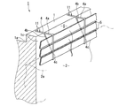
図1は、本発明の第1実施形態によるスロッシングおよび溢水抑制装置を示す要部拡大斜視図である。
[First Embodiment (FIGS. 1 to 4)]
FIG. 1 is an enlarged perspective view of a main part showing a sloshing and overflow control device according to a first embodiment of the present invention.
図1には、原子力発電プラントの使用済燃料貯蔵プールをプール内側から見た状態を示している。この図1に示すように、使用済燃料貯蔵プール1にはプール水2が収容されており、このプール水2の液面2aは燃料貯蔵プール1の上端部から一定距離低い位置に設定されている。
In FIG. 1, the state which looked at the spent fuel storage pool of a nuclear power plant from the pool inner side is shown. As shown in FIG. 1, the spent fuel storage pool 1 contains
燃料貯蔵プール1には、燃料交換等を行うための水平な作業床から立上り上面が水平な堤防状の周壁1aが設けられている。この周壁1aの上面に、逆L字形の支持部材4が固定部材11によりプール周方向に所定の間隔を設定して複数本固定配置されており、これらの支持部材4によって溢水抑制用の複数の仕切板3がプール1の内周壁1cに沿い、プール1の内周壁1cからプール1の内方に向かい、一定の間隔Sを開けて固定支持されている。
The fuel storage pool 1 is provided with an embankment-shaped
支持部材4は鋼製ロッドを素材として構成されており、プール周壁1aの上面からプール1の内方に向って略水平に突出する鋼材製の棒状をなす仕切板支持用の主ロッド部4aと、この主ロッド部4aの突出先端から下向きに垂下する補助ロッド部4cとにより逆L字形に構成されている。そして、主ロッド部4aの下面部位からプール1の内方に向い、プール周壁1aからプール1の内方に向って離間する方向に下向きに傾斜配置された補助ロッド部4bとを有している。
The
仕切板3は横長な縦板状のものであり、燃料貯蔵プール1内に収容されたプール水2の少なくとも液面部位の上下位置に、プール1の周壁内面に沿ってプール液面からプール水2の内部側に向って下方に1列に並んだ状態で垂下し、各仕切板3の間の上下方向には、それぞれ一定の狭いスリット5が開けてある。
The
これらの仕切板とプール1の内周壁との間に一定の間隔があけてあり、この間隔部位に、地震時に仕切板の頂部を超える水を導入するようにしてある。すなわち、燃料貯蔵プール1の周壁1aの内面側における少なくとも液面2a部位の上下部には、周壁1aの内面に沿ってプール水2の液面2aから液内部側に垂下する複数枚の横長な縦板状の仕切板3が上下方向にそれぞれ隙間をあけて配設されている。また、各仕切板3の上下方向には有為な間隔、すなわちプール水2が少量通過できる狭い間隔が開けてあり、燃料貯蔵プール1の周壁に向って一定の抵抗を受けてプール周壁側スリット5が開けてある。そして、仕切板3は十分な強度を有する透明樹脂素材によって構成されている。
A fixed interval is provided between these partition plates and the inner peripheral wall of the pool 1, and water exceeding the top of the partition plate is introduced into this interval portion during an earthquake. That is, at least the upper and lower portions of the
図2は燃料貯蔵プール1を上方から見た状態を示す全体平面図であり、図3は図2のA−A線断面図(縦断面図)である。図4は、図3のB矢視図(右側面図)である。 2 is an overall plan view showing the fuel storage pool 1 as viewed from above, and FIG. 3 is a cross-sectional view (vertical cross-sectional view) taken along line AA of FIG. 4 is a view (right side view) of FIG.
図2〜図4に示すように、燃料貯蔵プール1は四角形、例えば平面視長方形状をなしており、この燃料貯蔵プール1の各隅角部は円弧状に形成されている。プール1の周壁内面側における少なくとも液面部位の上下部には、周壁1aの内面に沿ってプール水2の液面からプール水2の内部側に垂下する複数枚の横長な縦板状の仕切板3を上下方向にそれぞれ隙間をあけて配設してある。
As shown in FIGS. 2 to 4, the fuel storage pool 1 has a square shape, for example, a rectangular shape in plan view, and each corner portion of the fuel storage pool 1 is formed in an arc shape. A plurality of horizontally long vertical partition walls that hang from the liquid surface of the
そして、これら仕切板3がプール1の側壁部位に固定配置されて、燃料貯蔵プール1の側面に沿うように設置されている。
These
さらに、燃料貯蔵プール1の隅部に曲面形状を有するプール隅仕切板6が設置されている。これにより、使用済燃料貯蔵プール1内に対する外部からの視認性を阻害しない構成となっている。
Furthermore, a pool
このように構成された本実施形態において、地震時にプール水2のスロッシングが生じた場合、プール水2は燃料貯蔵プール1の壁面に押し寄せる前に仕切板3により遮られる。
In the present embodiment configured as described above, when sloshing of the
仕切板3に押し寄せるプール水2の一部は仕切板3間のスリット5を通過することで乱流が生じ、これによりエネルギのロスが期待され、スロッシングの抑制に貢献する。
A part of the
また、仕切板3の上部を乗り越えてしまうプール水2は仕切板3と燃料貯蔵プール1の壁面との空間Sに着水することで、本来プール周壁1aを越えると予測される溢水量を低減することができる。
Further, the
さらに、燃料貯蔵プール1内の全周にわたり設置された仕切板3は透明性を有するため、燃料貯蔵プール1内の様子を監視する際に外部から視認性を阻害しない。
Furthermore, since the
このように構成された本実施形態形態において、スロッシングにより燃料貯蔵プール1の隅に押し寄せるプール水2はプール隅仕切板6で受け止められ、プール水2の狭い範囲への集中的な押し寄せを抑制することができる。この結果、燃料貯蔵プール1の隅にて生じる局所的な波高上昇による溢水にも対応することが可能となり、かつ視認性を阻害されることもない。
In the present embodiment configured as described above, the
[第2実施形態(図5)]
図5は、本発明の第2実施形態によるスロッシングおよび溢水抑制装置を示す要部拡大縦断面図である。なお、前述の第1実施形態と同一の構成部分には、図2と同一の符号を付して説明を省略する。
[Second Embodiment (FIG. 5)]
FIG. 5 is an enlarged vertical sectional view of a main part showing a sloshing and overflow control device according to a second embodiment of the present invention. Note that the same components as those in the first embodiment described above are denoted by the same reference numerals as those in FIG.
図5に示すように、本実施形態では燃料貯蔵プール1の内周壁面に沿って仕切板3が傾斜状に設置されている。すなわち、仕切板はプール周壁1aの上面に設けられた支持部材により支持されており、これらの支持部材は、プール周壁1aの上面からプール1の内方に向って略水平に突出する鋼材製の棒状をなす仕切板支持用主ロッド部4aと、この主ロッド部4aの下端側からプール周壁側に向って傾斜状に立上り、主ロッド部4aに連結された鋼材製の補助ロッド部4cとを備えている。
As shown in FIG. 5, in this embodiment, the
そして、燃料貯蔵プール1の隅部には曲面形状を有するプール隅仕切板6が設置されている。
Then, a pool
このように構成された本実施形態において、スロッシングにより燃料貯蔵プール1の隅に押し寄せるプール水2はプール隅仕切板6で受け止められ、プール水2の狭い範囲への集中的な押し寄せを抑制することができる。この結果、燃料貯蔵プール1の隅にて生じる局所的な波高上昇による溢水にも対応することが可能となる。
In this embodiment configured as described above, the
[第3実施形態(図6)]
図6は、本発明の第3実施形態によるスロッシングおよび溢水抑制装置を示す要部拡大縦断面図である。なお、前述の第1実施形態と同一の構成には図2と同一の符号を付して説明を省略する。
[Third Embodiment (FIG. 6)]
FIG. 6 is an enlarged vertical cross-sectional view of a main part showing a sloshing and overflow control device according to a third embodiment of the present invention. In addition, the same code | symbol as FIG. 2 is attached | subjected to the structure same as the above-mentioned 1st Embodiment, and description is abbreviate | omitted.
図6に示すように、燃料貯蔵プール1の側壁に固定されている支持部材4に代えて、スライド機構8付きの鋼材製ロッド7を有するスロッシングおよび溢水抑制装置である。
As shown in FIG. 6, in place of the
スライド機構8は、プール周壁1aの上面からプール1の内方に向って略水平に突出する鋼材製の棒状をなす仕切板支持用の主ロッド部4aを、周壁1aの上面に設置したガイド部材12によって水平方向にスライド可能に支持させ、係止具13によって所定位置に固定できる構成としたものである。
The slide mechanism 8 is a guide member in which a
このように構成された本実施形態によれば、水平方向に伸縮可能なスライド機構により、仕切板3を燃料貯蔵プール1の側壁から有為な距離Lに調整することが可能となる。
According to the present embodiment configured as described above, the
この結果、前記各実施形態に加え、燃料交換機による燃料取出し、装荷の作業を阻害しないものとすることができる。 As a result, in addition to the above-described embodiments, it is possible not to impede the work of fuel removal and loading by the fuel changer.
[第4実施形態(図7)]
図7は、本発明の第3実施形態によるスロッシングおよび溢水抑制装置を示す要部拡大縦断面図である。なお、前述の第1実施形態と同一の構成には図2と同一の符号を付して説明を省略する。
[Fourth Embodiment (FIG. 7)]
FIG. 7 is an enlarged vertical cross-sectional view of a main part showing a sloshing and overflow control device according to a third embodiment of the present invention. In addition, the same code | symbol as FIG. 2 is attached | subjected to the structure same as the above-mentioned 1st Embodiment, and description is abbreviate | omitted.
本実施形態が第1実施形態と異なる点は、第1実施形態に示した平板状の仕切板3に代えて、仕切板を波形仕切板8aとした点にある。すなわち、この波形仕切板8aは板厚方向に曲げを形成して、板面を波形に構成したものである。そして、図5に示した第2実施形態と同様に、上端側がプール1の内方に向って水平に突出した支持部材4の先端に連結支持されており、下端側がプール周壁内面側に接する配置で設けられている。
The present embodiment differs from the first embodiment in that the partition plate is a
このように構成された本実施形態においては、地震時によるスロッシング発生時には波形仕切板8aの表面を通過するプール水2に対し、その形状により回転成分が生じ、これによりプール水2に乱流が生じる。
In the present embodiment configured as described above, when sloshing occurs due to an earthquake, a rotational component is generated due to the shape of the
この結果、前記各実施形態と同等以上のスロッシングのエネルギ損失が期待され、スロッシング抑制について、より寄与することができ、溢水量の低減が図れるものとなる。 As a result, an energy loss of sloshing equivalent to or higher than that of each of the above embodiments is expected, and the sloshing suppression can be further contributed, and the amount of overflow can be reduced.
1‥使用済燃料貯蔵プール
1a‥プール周壁
1b‥作業床
1c‥内周壁
2‥プール水
2a‥液面
3‥仕切板
4‥支持部材
4a‥主ロッド部
4b‥補助ロッド部
4c‥補助ロッド部
5‥プール周壁側スリット
6‥プール隅仕切板
7‥鋼材製ロッド
8‥スライド機構
8a‥波形仕切板
11‥固定部材
12‥ガイド部材
S‥間隔
L‥距離
DESCRIPTION OF SYMBOLS 1 ... Spent
Claims (6)
Priority Applications (1)
| Application Number | Priority Date | Filing Date | Title |
|---|---|---|---|
| JP2008265485A JP4896942B2 (en) | 2008-10-14 | 2008-10-14 | Sloshing and overflow control device |
Applications Claiming Priority (1)
| Application Number | Priority Date | Filing Date | Title |
|---|---|---|---|
| JP2008265485A JP4896942B2 (en) | 2008-10-14 | 2008-10-14 | Sloshing and overflow control device |
Publications (2)
| Publication Number | Publication Date |
|---|---|
| JP2010096537A true JP2010096537A (en) | 2010-04-30 |
| JP4896942B2 JP4896942B2 (en) | 2012-03-14 |
Family
ID=42258338
Family Applications (1)
| Application Number | Title | Priority Date | Filing Date |
|---|---|---|---|
| JP2008265485A Expired - Fee Related JP4896942B2 (en) | 2008-10-14 | 2008-10-14 | Sloshing and overflow control device |
Country Status (1)
| Country | Link |
|---|---|
| JP (1) | JP4896942B2 (en) |
Citations (23)
| Publication number | Priority date | Publication date | Assignee | Title |
|---|---|---|---|---|
| JPS5590590A (en) * | 1978-12-28 | 1980-07-09 | Matsumura Sekiyu Kenkyusho:Kk | Cutting oil |
| JPS5985995A (en) * | 1982-11-10 | 1984-05-18 | 株式会社日立製作所 | Reactor control rod drive mechanisms |
| JPS59171893A (en) * | 1983-03-18 | 1984-09-28 | 株式会社東芝 | Fuel pool device |
| JPS6035095A (en) * | 1983-08-05 | 1985-02-22 | Idemitsu Kosan Co Ltd | Fluid for traction drive |
| JPS60243596A (en) * | 1984-05-18 | 1985-12-03 | 株式会社東芝 | Sloshing preventive device |
| JPS60243597A (en) * | 1984-05-18 | 1985-12-03 | 株式会社東芝 | Fuel pool facility |
| JPS61104990A (en) * | 1984-10-25 | 1986-05-23 | 株式会社東芝 | Liquid-surface rocking inhibitor |
| JPS61115876A (en) * | 1984-10-31 | 1986-06-03 | 株式会社東芝 | Sloshing preventive device |
| JPS61165493A (en) * | 1985-12-28 | 1986-07-26 | 植村 厚一 | Method of propelling excavator |
| JPS61271499A (en) * | 1985-05-27 | 1986-12-01 | 鹿島建設株式会社 | Water controller |
| JPS6230994A (en) * | 1985-08-02 | 1987-02-09 | 株式会社東芝 | Breakwater facility for pool water in nuclear reactor pool |
| JPS62215893A (en) * | 1986-03-18 | 1987-09-22 | 株式会社東芝 | Spent fuel storage pool |
| JPS62293195A (en) * | 1986-06-13 | 1987-12-19 | 株式会社東芝 | Nuclear-reactor storage pool |
| JPH02242778A (en) * | 1989-03-13 | 1990-09-27 | Hitachi Ltd | Liquid surface splashing preventive apparatus |
| JPH06146248A (en) * | 1992-11-13 | 1994-05-27 | Aqua Tec Kk | River refuse collecting facility |
| JPH06345184A (en) * | 1993-06-15 | 1994-12-20 | Mitsubishi Heavy Ind Ltd | Tank with device for suppressing liquid fluctuation |
| JPH0815482A (en) * | 1994-06-28 | 1996-01-19 | Toshiba Corp | Spent fuel storage pool equipment |
| JPH08101296A (en) * | 1994-09-30 | 1996-04-16 | Toshiba Corp | Sloshing overflow preventer |
| JP2006298481A (en) * | 2005-04-25 | 2006-11-02 | Tanoshi Kawada | Anti-sloshing device in liquid tank |
| JP2006317230A (en) * | 2005-05-11 | 2006-11-24 | Toshiba Corp | Fence structure of fuel storage pool |
| JP2006329799A (en) * | 2005-05-26 | 2006-12-07 | Toshiba Corp | Sloshing overflow prevention device |
| JP2007163204A (en) * | 2005-12-12 | 2007-06-28 | Toshiba Corp | Reactor building and method for renovating it |
| JP2009216538A (en) * | 2008-03-11 | 2009-09-24 | Taisei Corp | Sloshing overflow preventing device |
-
2008
- 2008-10-14 JP JP2008265485A patent/JP4896942B2/en not_active Expired - Fee Related
Patent Citations (23)
| Publication number | Priority date | Publication date | Assignee | Title |
|---|---|---|---|---|
| JPS5590590A (en) * | 1978-12-28 | 1980-07-09 | Matsumura Sekiyu Kenkyusho:Kk | Cutting oil |
| JPS5985995A (en) * | 1982-11-10 | 1984-05-18 | 株式会社日立製作所 | Reactor control rod drive mechanisms |
| JPS59171893A (en) * | 1983-03-18 | 1984-09-28 | 株式会社東芝 | Fuel pool device |
| JPS6035095A (en) * | 1983-08-05 | 1985-02-22 | Idemitsu Kosan Co Ltd | Fluid for traction drive |
| JPS60243596A (en) * | 1984-05-18 | 1985-12-03 | 株式会社東芝 | Sloshing preventive device |
| JPS60243597A (en) * | 1984-05-18 | 1985-12-03 | 株式会社東芝 | Fuel pool facility |
| JPS61104990A (en) * | 1984-10-25 | 1986-05-23 | 株式会社東芝 | Liquid-surface rocking inhibitor |
| JPS61115876A (en) * | 1984-10-31 | 1986-06-03 | 株式会社東芝 | Sloshing preventive device |
| JPS61271499A (en) * | 1985-05-27 | 1986-12-01 | 鹿島建設株式会社 | Water controller |
| JPS6230994A (en) * | 1985-08-02 | 1987-02-09 | 株式会社東芝 | Breakwater facility for pool water in nuclear reactor pool |
| JPS61165493A (en) * | 1985-12-28 | 1986-07-26 | 植村 厚一 | Method of propelling excavator |
| JPS62215893A (en) * | 1986-03-18 | 1987-09-22 | 株式会社東芝 | Spent fuel storage pool |
| JPS62293195A (en) * | 1986-06-13 | 1987-12-19 | 株式会社東芝 | Nuclear-reactor storage pool |
| JPH02242778A (en) * | 1989-03-13 | 1990-09-27 | Hitachi Ltd | Liquid surface splashing preventive apparatus |
| JPH06146248A (en) * | 1992-11-13 | 1994-05-27 | Aqua Tec Kk | River refuse collecting facility |
| JPH06345184A (en) * | 1993-06-15 | 1994-12-20 | Mitsubishi Heavy Ind Ltd | Tank with device for suppressing liquid fluctuation |
| JPH0815482A (en) * | 1994-06-28 | 1996-01-19 | Toshiba Corp | Spent fuel storage pool equipment |
| JPH08101296A (en) * | 1994-09-30 | 1996-04-16 | Toshiba Corp | Sloshing overflow preventer |
| JP2006298481A (en) * | 2005-04-25 | 2006-11-02 | Tanoshi Kawada | Anti-sloshing device in liquid tank |
| JP2006317230A (en) * | 2005-05-11 | 2006-11-24 | Toshiba Corp | Fence structure of fuel storage pool |
| JP2006329799A (en) * | 2005-05-26 | 2006-12-07 | Toshiba Corp | Sloshing overflow prevention device |
| JP2007163204A (en) * | 2005-12-12 | 2007-06-28 | Toshiba Corp | Reactor building and method for renovating it |
| JP2009216538A (en) * | 2008-03-11 | 2009-09-24 | Taisei Corp | Sloshing overflow preventing device |
Also Published As
| Publication number | Publication date |
|---|---|
| JP4896942B2 (en) | 2012-03-14 |
Similar Documents
| Publication | Publication Date | Title |
|---|---|---|
| US10910119B2 (en) | Self-alignment method of neutron absorbing apparatus for reactivity mitigation in nuclear fuel storage systems | |
| JP2016142687A (en) | Nuclear reactor containment structure | |
| JP4896942B2 (en) | Sloshing and overflow control device | |
| US20210280330A1 (en) | Nuclear reactor dismantlement system | |
| JP5173012B2 (en) | Spent fuel pool water monitoring device | |
| JPH07128485A (en) | Fuel pool equipment | |
| JP2009150703A (en) | Spent fuel pool water monitoring device | |
| JP2009257996A (en) | Sloshing prevention device | |
| JP4971224B2 (en) | Sloshing overflow prevention device | |
| JP4922325B2 (en) | Spent fuel pool equipment | |
| JP2006317230A (en) | Fence structure of fuel storage pool | |
| JP6462501B2 (en) | Drain sump protection structure and containment vessel | |
| JP2016197051A (en) | Corium holding arrangement | |
| JP2009121925A (en) | Sloshing overflow suppression device and fuel storage pool using it | |
| JP2011053084A (en) | Nuclear power plant | |
| JP4990308B2 (en) | Sloshing and overflow prevention device for spent fuel storage pool | |
| JP6034735B2 (en) | Filter vent building | |
| KR100999836B1 (en) | core catcher for the liquid metal reactor | |
| JP2014173860A (en) | Safety enhancement building for nuclear facility | |
| JP5569858B2 (en) | Fence prevention fence for storage tank | |
| JP5315723B2 (en) | Shielding structure of fluid transfer piping for transferring low concentration radioactive fluid | |
| JP2006010313A (en) | Radioactive material storage building | |
| JP6654986B2 (en) | Racks for nuclear fuel storage | |
| JP4492728B2 (en) | Shielding structure | |
| JP4657224B2 (en) | Radioactive material storage facility |
Legal Events
| Date | Code | Title | Description |
|---|---|---|---|
| RD04 | Notification of resignation of power of attorney |
Free format text: JAPANESE INTERMEDIATE CODE: A7424 Effective date: 20100424 |
|
| A621 | Written request for application examination |
Free format text: JAPANESE INTERMEDIATE CODE: A621 Effective date: 20110127 |
|
| A977 | Report on retrieval |
Free format text: JAPANESE INTERMEDIATE CODE: A971007 Effective date: 20110912 |
|
| A131 | Notification of reasons for refusal |
Free format text: JAPANESE INTERMEDIATE CODE: A131 Effective date: 20110927 |
|
| A521 | Written amendment |
Free format text: JAPANESE INTERMEDIATE CODE: A523 Effective date: 20111109 |
|
| TRDD | Decision of grant or rejection written | ||
| A01 | Written decision to grant a patent or to grant a registration (utility model) |
Free format text: JAPANESE INTERMEDIATE CODE: A01 Effective date: 20111129 |
|
| A01 | Written decision to grant a patent or to grant a registration (utility model) |
Free format text: JAPANESE INTERMEDIATE CODE: A01 |
|
| A61 | First payment of annual fees (during grant procedure) |
Free format text: JAPANESE INTERMEDIATE CODE: A61 Effective date: 20111221 |
|
| FPAY | Renewal fee payment (event date is renewal date of database) |
Free format text: PAYMENT UNTIL: 20150106 Year of fee payment: 3 |
|
| LAPS | Cancellation because of no payment of annual fees |