JP2010096102A - Variable valve train - Google Patents
Variable valve train Download PDFInfo
- Publication number
- JP2010096102A JP2010096102A JP2008268016A JP2008268016A JP2010096102A JP 2010096102 A JP2010096102 A JP 2010096102A JP 2008268016 A JP2008268016 A JP 2008268016A JP 2008268016 A JP2008268016 A JP 2008268016A JP 2010096102 A JP2010096102 A JP 2010096102A
- Authority
- JP
- Japan
- Prior art keywords
- camshaft
- guide groove
- rotating member
- displaced
- drive
- Prior art date
- Legal status (The legal status is an assumption and is not a legal conclusion. Google has not performed a legal analysis and makes no representation as to the accuracy of the status listed.)
- Granted
Links
Images


Classifications
-
- F—MECHANICAL ENGINEERING; LIGHTING; HEATING; WEAPONS; BLASTING
- F01—MACHINES OR ENGINES IN GENERAL; ENGINE PLANTS IN GENERAL; STEAM ENGINES
- F01L—CYCLICALLY OPERATING VALVES FOR MACHINES OR ENGINES
- F01L13/00—Modifications of valve-gear to facilitate reversing, braking, starting, changing compression ratio, or other specific operations
- F01L13/0015—Modifications of valve-gear to facilitate reversing, braking, starting, changing compression ratio, or other specific operations for optimising engine performances by modifying valve lift according to various working parameters, e.g. rotational speed, load, torque
- F01L13/0036—Modifications of valve-gear to facilitate reversing, braking, starting, changing compression ratio, or other specific operations for optimising engine performances by modifying valve lift according to various working parameters, e.g. rotational speed, load, torque the valves being driven by two or more cams with different shape, size or timing or a single cam profiled in axial and radial direction
- F01L2013/0052—Modifications of valve-gear to facilitate reversing, braking, starting, changing compression ratio, or other specific operations for optimising engine performances by modifying valve lift according to various working parameters, e.g. rotational speed, load, torque the valves being driven by two or more cams with different shape, size or timing or a single cam profiled in axial and radial direction with cams provided on an axially slidable sleeve
Abstract
Description
本発明は、内燃機関の運転状況に応じてバルブの駆動状態を変更する可変動弁機構に関する。 The present invention relates to a variable valve mechanism that changes a driving state of a valve in accordance with an operation state of an internal combustion engine.
可変動弁機構の中には、図7に示す従来例1(特許文献1)の可変動弁機構80のように、カムシャフト10にその長さ方向に並べて、同方向に向かうに従いカムプロフィールが連続的に変わる複数のテーパー状の連続カム面83,83,83が突設され、図7(a)(b)に示すように、該カムシャフト81をその長さ方向に変位させることによって、各連続カム面83,83,83で駆動するバルブ8,8・・のリフト量を変更するものがある。
Among the variable valve mechanisms, like the
また、中には、図8に示す従来例2(非特許文献1)の可変動弁機構90のように、カムシャフト91に、該カムシャフト91と伴に回転する複数の回転部材92,92,92が外挿され、各回転部材92,92,92の外周面に一種類の駆動用カム面93,93・・がそれぞれ形成され、各駆動機構94,94,94で各回転部材92,92,92をカムシャフト91の長さ方向に変位させることによって、図8(b)に示すように、各回転部材92,92,92がその駆動用カム面93,93・・でバルブ8,8・・を駆動する実行状態と、図8(a)に示すように、該駆動用カム面93,93・・でバルブ8,8・・を駆動しない休止状態との間でバルブ8,8・・の駆動状態を変更するものもある。
ところが、従来例1の場合には、バルブ8,8・・の駆動状態を切り換える際に、比較的質量の大きいカムシャフト81全体をその長さ方向に、各連続カム面83,83,83を変位させたい長さ分も変位させるため、効率が悪い。
However, in the case of the conventional example 1, when switching the driving state of the
また、従来例2の場合には、バルブ8,8・・の駆動状態を切り換える際に、比較的質量の小さい各回転部材92,92,92のみをカムシャフト91の長さ方向に変位させるため、その点では、従来例1に比べて効率的であるが、各回転部材92,92,92毎に駆動機構94,94,94(各回転部材92毎に2個のソレノイド)を設けなければならず、その点では効率が悪い
Further, in the case of the conventional example 2, when the driving state of the
そこで、各回転部材毎に駆動機構を設けることなく、カムシャフト全体をその長さ方向に、各カム面を変位させたい長さ分未満の長さ分だけ変位させるだけで、各カム面を該変位させたい長さ分だけ変位させることができるようにすることを目的とする。 Therefore, without providing a driving mechanism for each rotating member, each cam surface is simply moved by moving the entire cam shaft in the length direction by a length less than the length for which each cam surface is to be displaced. It is an object of the present invention to be able to be displaced by the length to be displaced.
上記目的を達成するため、本発明の可変動弁機構は、クランクシャフトの回転に従い周方向に回転し、長さ方向に変位可能に設けられたカムシャフトと、前記カムシャフトに該カムシャフトの長さ方向に並べて該長さ方向に相対変位可能、該カムシャフトの周方向に相対変位不能にそれぞれ外挿され、外周面に、該カムシャフトと伴に回転するの従いバルブを駆動する少なくとも一種類の駆動用カム面をそれぞれ備えた複数の回転部材と、前記カムシャフトを該カムシャフトの長さ方向に変位させる駆動機構と、各回転部材毎に設けられ、前記カムシャフトが該カムシャフトの長さ方向に変位すると、該カムシャフトの回転力を該カムシャフトの変位方向への変位力に変えて各回転部材に伝えて、該カムシャフトに対して各回転部材を該カムシャフトの変位方向に相対変位させる複数の変位量増幅機構とを含み構成され、前記カムシャフトを前記駆動機構で該カムシャフトの長さ方向に変位させ、該カムシャフトに対して各回転部材を各変位量増幅機構で該カムシャフトの変位方向に相対変位させることによって、各回転部材が前記一種類の駆動用カム面でバルブを駆動する状態と該一種類の駆動用カム面でバルブを駆動しない状態との間でバルブの駆動状態を変更する。 In order to achieve the above object, a variable valve mechanism according to the present invention includes a camshaft that rotates in a circumferential direction in accordance with the rotation of a crankshaft and is displaceable in a lengthwise direction, At least one type of driving valve that is arranged in the longitudinal direction and can be displaced relatively in the longitudinal direction and not in the circumferential direction of the camshaft, and rotates on the outer circumferential surface together with the camshaft. A plurality of rotating members each having a driving cam surface, a driving mechanism for displacing the camshaft in the longitudinal direction of the camshaft, and each rotating member, the camshaft being the length of the camshaft. When the camshaft is displaced in the vertical direction, the rotational force of the camshaft is changed to a displacement force in the displacement direction of the camshaft and transmitted to each rotary member, and each rotary member is transferred to the camshaft. A plurality of displacement amount amplifying mechanisms for relative displacement in the displacement direction of the shaft, and the camshaft is displaced in the lengthwise direction of the camshaft by the drive mechanism, and each rotating member is moved to the camshaft. A state in which each rotating member drives the valve with the one type of driving cam surface and the valve is not driven with the one type of driving cam surface by relative displacement in the displacement direction of the camshaft by the displacement amount amplification mechanism. The valve drive state is changed between states.
前記回転部材は、特に限定されないが、次の[1]〜[3]の場合が例として挙げられる。
[1]前記回転部材は、前記一種類の駆動用カム面以外のカム面は備えず、前記一種類の駆動用カム面でバルブを駆動しない状態の時には、該回転部材はバルブに直接的にもロッカアーム等の介在部材を介して間接的にも当接しない場合。
[2]前記回転部材は、前記一種類の駆動用カム面の前記カムシャフトの長さ方向側に、バルブを駆動しない一種類の休止用カム面を備え、前記一種類の駆動用カム面でバルブを駆動しない状態の時には、該一種類の休止用カム面でバルブに直接的に又はロッカアーム等の介在部材を介して間接的に当接する場合。
[3]前記回転部材は、前記一種類の駆動用カム面の前記カムシャフトの長さ方向側に、他種類の駆動用カム面を備え、前記一種類の駆動用カム面でバルブを駆動しない状態の時には、該他種類の駆動用カム面でバルブを駆動する場合。
Although the said rotation member is not specifically limited, The case of following [1]-[3] is mentioned as an example.
[1] The rotating member does not include a cam surface other than the one type of driving cam surface, and when the valve is not driven by the one type of driving cam surface, the rotating member directly contacts the valve. No contact with the rocker arm or other intervening member.
[2] The rotating member includes a one-type cam cam surface that does not drive a valve on a length direction side of the cam shaft of the one type driving cam surface. When the valve is not driven, the one type of cam surface for resting directly contacts the valve or indirectly through an intervening member such as a rocker arm.
[3] The rotating member includes another type of driving cam surface on the longitudinal direction side of the cam shaft of the one type of driving cam surface, and does not drive the valve with the one type of driving cam surface. When the valve is driven with the other type of driving cam surface in the state.
上記[2][3]の場合、前記一種類の駆動用カム面と、前記一種類の休止用カム面又は前記他種類の駆動用カム面との2種類のカム面は、特に限定されないが、次の[i][ii]の場合が例として挙げられる。
[i]前記2種類のカム面は、両者間の境界でカムプロフィールが断続的に変わる場合。
[ii]前記回転部材は、外周面に、前記カムシャフトの長さ方向に進むに従いカムプロフィールが連続的に変わるテーパー状の連続カム面を備え、該連続カム面のいずれかの全周部分が前記2種類のカム面のうちの一方であって、該全周部分とは異なる他のいずれかの全周部分が前記2種類のカム面のうちの他方である場合。
In the case of the above [2] and [3], there are no particular limitations on the two types of cam surfaces: the one type of driving cam surface and the one type of resting cam surface or the other type of driving cam surface. The following cases [i] and [ii] are given as examples.
[I] The two cam surfaces have intermittent cam profile changes at the boundary between them.
[Ii] The rotating member includes a tapered continuous cam surface whose cam profile continuously changes as the cam shaft advances in the length direction of the camshaft on the outer peripheral surface, and the entire peripheral portion of any one of the continuous cam surfaces is One of the two types of cam surfaces, and one of the other circumferential portions different from the circumferential portion is the other of the two types of cam surfaces.
前記変位量増幅機構は、特に限定されないが、前記回転部材の外周面に設けられて該外周面の周方向に延び、前記カムシャフトの回転方向に向かうに従い該カムシャフトの長さ方向一方にずれる一方の案内溝と、前記回転部材の外周面に設けられて該外周面の周方向に延び、前記カムシャフトの回転方向に向かうに従い該カムシャフトの長さ方向他方にずれて前記一方の案内溝と交差部で交差する他方の案内溝と、前記カムシャフトを支持したシリンダヘッドに設けられ、前記カムシャフトが該カムシャフトの長さ方向一方に変位すると、前記一方の案内溝に係合して前記回転部材を該カムシャフトの回転に従い該カムシャフトの長さ方向一方に変位させ、前記カムシャフトが該カムシャフトの長さ方向他方に変位すると、前記他方の案内溝に係合して前記回転部材を該カムシャフトの回転に従い該カムシャフトの長さ方向他方に変位させる係合ピンとを含み構成されていることが好ましい。 Although the displacement amount amplifying mechanism is not particularly limited, the displacement amount amplifying mechanism is provided on the outer peripheral surface of the rotating member, extends in the circumferential direction of the outer peripheral surface, and shifts to one of the length directions of the cam shaft as it goes in the rotating direction of the cam shaft. One guide groove and the one guide groove which is provided on the outer peripheral surface of the rotating member and extends in the circumferential direction of the outer peripheral surface and shifts to the other in the longitudinal direction of the cam shaft as it goes in the rotational direction of the cam shaft. Is provided in the cylinder head that supports the camshaft, and when the camshaft is displaced in one length direction of the camshaft, it engages with the one guide groove. When the rotating member is displaced in one length direction of the cam shaft according to the rotation of the cam shaft, and the cam shaft is displaced in the other length direction of the cam shaft, the other guide groove It is preferable that the rotating member engaging is configured including an engagement pin to be displaced in the longitudinal direction other of the cam shaft in accordance with rotation of the cam shaft.
ここで、前記係合ピンは、特に限定されないが、該係合ピンの前記一方の案内溝及び前記他方の案内溝に係合する係合部に、前記一方の案内溝に係合した際には、該係合ピンが前記交差部で前記他方の案内溝に逸れるのを防止し、前記他方の案内溝に係合した際には、該係合ピンが前記交差部で前記一方の案内溝に逸れるのを防止する逸れ防止部を備えていることが好ましい。 Here, the engagement pin is not particularly limited. When the engagement pin is engaged with the one guide groove, the engagement pin is engaged with the one guide groove and the other guide groove. Prevents the engagement pin from moving to the other guide groove at the intersection, and when the engagement pin is engaged with the other guide groove, the engagement pin is moved to the one guide groove at the intersection. It is preferable to provide an escape prevention portion that prevents the escape.
前記逸れ防止部は、特に限定されないが、前記係合部から前記カムシャフトの周方向に延びる突起部である場合や、前記係合部自体が、前記カムシャフトの周方向に延びる形状に形成されてなる場合等が例として挙げられる。 The escape prevention part is not particularly limited, but may be a protrusion that extends from the engagement part in the circumferential direction of the camshaft, or the engagement part itself is formed in a shape that extends in the circumferential direction of the camshaft. The case where it becomes is mentioned as an example.
本発明によれば、変位量増幅機構があるため、カムシャフトをその長さ方向に、各駆動用カム面を変位させたい長さ分未満の長さ分だけ変位させるだけで、各駆動用カム面を該変位させたい長さ分だけ変位させることができる。また、カムシャフトを駆動機構で変位させるだけでよいので、各回転部材毎に駆動機構を設ける必要もない。 According to the present invention, since there is a displacement amount amplifying mechanism, each drive cam is simply displaced in the length direction by a length less than the length of each drive cam surface to be displaced. The surface can be displaced by the length to be displaced. In addition, since it is only necessary to displace the camshaft by the drive mechanism, it is not necessary to provide a drive mechanism for each rotating member.
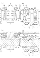
本発明の可変動弁機構9は、クランクシャフト(図示略)の回転に従い周方向に回転し、長さ方向に変位可能に設けられたカムシャフト10と、カムシャフト10にその長さ方向に並べて同方向に相対変位可能、該カムシャフト10の周方向に相対変位不能にそれぞれ外挿され、外周面に、該カムシャフト10と伴に回転するの従いバルブ8,8・・を駆動する少なくとも一種類の駆動用カム面23,23,23をそれぞれ備えた複数の回転部材20,20,20と、カムシャフト10をその長さ方向に変位させる駆動機構30と、各回転部材20,20,20毎に設けられ、カムシャフト10がその長さ方向に変位すると、該カムシャフト10の回転力を該カムシャフト10の変位方向への変位力に変えて各回転部材20,20,20に伝えて、該カムシャフト10に対して各回転部材20,20,20を該カムシャフト10の変位方向に相対変位させる複数の変位量増幅機構40,40,40とを含み構成されている。
The
そして、カムシャフト10を駆動機構30で該カムシャフト10の長さ方向に変位させ、該カムシャフト10に対して各回転部材20,20,20を各変位量増幅機構40,40,40で該カムシャフト10の変位方向に相対変位させることによって、各回転部材20,20,20が上記一種類の駆動用カム面23,23,23でバルブ8,8・・を駆動する状態と該一種類の駆動用カム面23,23,23でバルブ8,8・・を駆動しない状態との間でバルブ8,8・・の駆動状態を変更する。
Then, the
ここで、変位量増幅機構40は、回転部材20の外周面に設けられて該外周面の周方向に延び、カムシャフト10の回転方向に向かうに従い該カムシャフト10の長さ方向一方にずれる一方の案内溝41と、回転部材20の外周面に設けられて該外周面の周方向に延び、カムシャフト10の回転方向に向かうに従い該カムシャフト10の長さ方向他方にずれて一方の案内溝41と交差部Xで交差する他方の案内溝42と、カムシャフト10を支持したシリンダヘッド6に設けられ、カムシャフト10がその長さ方向一方に変位すると、一方の案内溝41に係合して回転部材20を該カムシャフト10の回転に従い該カムシャフト10の長さ方向一方に変位させ、カムシャフト10がその長さ方向他方に変位すると、他方の案内溝42に係合して回転部材20を該カムシャフト10の回転に従い該カムシャフト10の長さ方向他方に変位させる係合ピン43とを含み構成されている。
Here, the displacement amount amplifying
そして、係合ピン43は、そのピンの一方の案内溝41及び他方の案内溝42に係合する係合部に、一方の案内溝41に係合した際には、該係合ピン43が交差部Xで他方の案内溝42に逸れるのを防止し、他方の案内溝42に係合した際には、該係合ピン43が交差部Xで一方の案内溝41に逸れるのを防止する逸れ防止部43aを備えている。
When the engaging
図1〜図5に示す本実施例の可変動弁機構9は、3つの各シリンダに対してそれぞれ一対ずつ設けられた3対の吸気用又は排気用のバルブ8,8・・に対して設けられており、各バルブ8,8・・の駆動状態を、実行状態と休止状態との間で変更する。この可変動弁機構9は、次に示す1本のカムシャフト10と、3つの回転部材20,20,20と、1つの駆動機構30と、3つの変位量増幅機構40,40,40と、3つのロッカアーム50,50,50と、3対のバルブスプリング60,60・・とを含み構成されている。なお、以下においては、便宜上、カムシャフト10の長さ方向一方を右とし、他方を左としているが、右と左とが反対であってもよい。
The
[カムシャフト10]
カムシャフト10は左右方向に延びるシャフトであって、シリンダヘッド6に左右方向に間隔をおいて並設された複数の立壁部7,7・・に挿通されることによって、左右方向及び該カムシャフト10の周方向に変位可能に支持されている。このカムシャフト10は、その基端部11がクランクシャフト(図示略)に連結されており、該クランクシャフト(図示略)の回転に従い該カムシャフト10の周方向に回転する。このカムシャフト10の外周面における3つの各シリンダに隣接する左右方向に並ぶ3ヶ所には、各回転部材20,20,20を取り付けるための取付部12,12,12が設けられている。そして、各取付部12の左方には、カムシャフト10が右方向に変位した際に回転部材20に左側から当接して該回転部材20を右方向に押圧して駆動する右駆動用突起13が設けられ、各取付部12の右方には、カムシャフト10が左方向に変位した際に回転部材20に右側から当接して該回転部材20を左方向に押圧して駆動する左駆動用突起14が設けられている。
[Camshaft 10]
The
[回転部材20,20,20]
各回転部材20は、カムシャフト10に外挿される円筒形の部材であって、その内周面に設けられた被取付部22が、カムシャフト10の取付部12に左右方向に相対変位可能、該カムシャフト10の周方向に相対変位不能に係合している。この回転部材20は、その外周面の右部に、カムシャフト10と伴に回転するの従いバルブ8,8・・を駆動する駆動用カム面23を備え、外周面の左右中央部に、バルブ8,8を駆動しない休止用カム面24を備えている。詳しくは、駆動用カム面23は、その基本部分の断面形状が真円形で該真円形から突出したカムノーズ23aを備えている。その一方、休止用カム面24は、その全体の断面形状が真円形でカムノーズを備えていない。これら3つの各回転部材20,20,20は、互いに120度ずつ角度をずらして設置されている。
[Rotating
Each rotating
[駆動機構30]
駆動機構30は、カムシャフト10を左右方向に変位させるための機構であって、該カムシャフト10を右方向に駆動する右駆動部31と、左方向に駆動する左駆動部36とからなる。
[Drive mechanism 30]
The
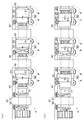
右駆動部31は、右駆動溝32と右駆動ピン33と右駆動用ソレノイド34とを含み構成されている。右駆動溝32は、カムシャフト10に突設された右駆動用拡径部15の外周面に凹設されて該カムシャフト10の周方向に延び、該カムシャフト10の回転方向に向かうに従い右方向にずれている。詳しくは、該右駆動溝32は、カムシャフト10の回転方向側の端部に位置する始端部32aが、その始端から左右にずれることなくカムシャフト10の回転方向の反対方向に真っ直ぐ延び、長さ方向中間部32bが、始端部32aの終りからカムシャフト10の回転方向の反対方向に延びて該回転方向の反対方向に向かうに従い左方向(回転方向に向かうに従い右方向)ずれ、終端部32cが、長さ方向中間部32bの終りから左右にずれることなくカムシャフト10の回転方向の反対方向に真っ直ぐ延びて該回転方向の反対方向に向かうに従い徐々に浅くなっている。右駆動ピン33は、その先後方向に延びるピンである。右駆動用ソレノイド34は、右駆動ピン33の後部をそのピンの先後方向に駆動可能に支持し、該右駆動ピン33をその先方に駆動することによって該右駆動ピン33の先端部を右駆動溝32に係合させる。
The
左駆動部36は、左駆動溝37と左駆動ピン38と左駆動用ソレノイド39とを含み構成されている。左駆動溝37は、カムシャフト10に突設された左駆動用拡径部16の外周面に凹設されて該カムシャフト10の周方向に延び、該カムシャフト10の回転方向に向かうに従い左方向にずれている。詳しくは、該左駆動溝37は、カムシャフト10の回転方向側の端部に位置する始端部37aが、その始端から左右にずれることなくカムシャフト10の回転方向の反対方向に真っ直ぐ延び、長さ方向中間部37bが、始端部37aの終りからカムシャフト10の回転方向の反対方向に延びて該回転方向の反対方向に向かうに従い右方向(回転方向に向かうに従い左方向)ずれ、終端部37cが、長さ方向中間部37bの終りから左右にずれることなくカムシャフト10の回転方向の反対方向に真っ直ぐ延びて該回転方向の反対方向に向かうに従い徐々に浅くなっている。左駆動ピン38は、その先後方向に延びるピンである。左駆動用ソレノイド39は、左駆動ピン38の後部をそのピンの先後方向に駆動可能に支持し、該左駆動ピン38をその先方に駆動することによって該左駆動ピン38の先端部を左駆動溝37に係合させる。
The
[変位量増幅機構40,40,40]
各変位量増幅機構40は、カムシャフト10が右方向に変位すると、該カムシャフト10の回転力を右方向への変位力に変えて回転部材20に伝えて、該カムシャフト10に対して該回転部材20を右方向に相対変位させ、カムシャフト10が左方向に変位すると、該カムシャフト10の回転力を左方向への変位力に変えて回転部材20に伝えて、該カムシャフト10に対して該回転部材20を左方向に相対変位させる機構である。この変位量増幅機構40は、次に示す右案内溝41及び左案内溝42と、係合ピン43と、変位用バネ48とを含み構成されている。
[
When the
右案内溝41は、回転部材20の外周面の左部に設けられて該外周面の周方向に延び、カムシャフト10の回転方向に向かうに従い右方向にずれている。また、左案内溝42は、回転部材20の外周面の左部に設けられて該外周面の周方向に延び、カムシャフト10の回転方向に向かうに従い左方向にずれて交差部Xで右案内溝41と交差している。詳しくは、右案内溝41及び左案内溝42のカムシャフト10の回転方向側の端部に位置する始端部41a,42aは、右案内溝41の始端部41aが右側になり、左案内溝42の始端部42aが左側になるように並んで、それらの始端からそれぞれ左右にずれることなくカムシャフト10の回転方向の反対方向に真っ直ぐ延びている。また、右案内溝41及び左案内溝42の長さ方向中間部41b,42bは、各始端部41a,42bの終りからカムシャフト10の回転方向の反対方向にそれぞれ延び、該回転方向の反対方向に向かうに従い、右案内溝41の長さ方向中間部41bは左方向(回転方向に向かうに従い右方向)に、左案内溝42の長さ方向中間部42bは右方向(回転方向に向かうに従い左方向)にそれぞれずれて、交差部Xで交差している。また、右案内溝41及び左案内溝42の終端部41c,42cは、各長さ方向中間部41b,42bの終りから、そのまま右案内溝41の終端部41cが左側になり、左案内溝42の終端部42cが右側になるように並んで、それぞれ左右にずれることなくカムシャフト10の回転方向の反対方向に真っ直ぐ延び、該回転方向の反対方向に向かうに従い徐々に浅くなっている。ここで、右案内溝41及び左案内溝42の長さ方向中間部41b,42bは、回転部材20の外周面におけるカムノーズ23aがバルブ8,8を駆動しない時に係合ピン43に係合する位置に設けられている。
The
係合ピン43は、その先後方向に延びるピンであって、カムシャフト10を支持したシリンダヘッド6に固定された有底筒状のボディ44の内側に該係合ピン43の後部が挿入されることによって、該ボディ44に該係合ピン43がその先後方向に変位可能に支持されている。そして、該ボディ44の底面と該係合ピン43の後端面との間に、該係合ピン43をその先方に押圧するバネ45が圧縮状態で介装されることによって、該係合ピン43の先端面が回転部材20の外周面の左部に押圧されている。また、この係合ピン43は、その先端部がカムシャフト10の周方向に延びる形状(断面視で長円形等の形状)に形成されてなる逸れ防止部43aを備え、該逸れ防止部43aは、該係合ピン43の先端部が右案内溝41に係合した際には、該係合ピン43の先端部が交差部Xで左案内溝42に逸れるのを防止し、該係合ピン43の先端部が左案内溝42に係合した際には、該係合ピン43の先端部が交差部Xで右案内溝41に逸れるのを防止する。
The
変位用バネ48は、回転部材20がカムシャフト10に対する左右方向へのストロークの右寄りにあるときには該回転部材20を右方向に押圧し、左寄りにあるときには該回転部材20を左方向に押圧する。詳しくは、この変位用バネ48は、左右方向に延び、長さ方向中間部がコイル状に巻かれたトーションコイルバネであって、回転部材20の内周面とカムシャフト10の外周面との間に介装されている。そして、該変位用バネ48の左右両端部は、回転部材20の内周面に左右方向に相対変位不能に係合し、長さ方向中間部は、カムシャフト10の外周面に設けられた正面視で凸状に湾曲した湾曲面49に当接している。
The
[ロッカアーム50,50,50]
各ロッカアーム50は、一対のバルブ8,8を同時に駆動する2弁一体型のアームであって、カムシャフト10の径と平行に延び、基端部がラッシュアジャスタ59によって揺動可能に支持され、長さ方向中間部に、回転部材20の駆動用カム面23及び休止用カム面24に択一的に当接するローラ51を備え、先端部が左右に分かれて一対のバルブ8,8に当接している。
[
Each
[バルブスプリング60,60・・]
各バルブスプリング60は、バルブ8を閉じる方向に付勢するためのリターンスプリングである。
[
Each
次に、本実施例の可変動弁機構9を用いて、バルブ8,8の駆動状態を、実行状態と休止状態との間で切り換える際の様子を、{1}実行状態から休止状態に切り換える際 と{2}休止状態から実行状態に切り換える際 とに分けて以下に説明する。
Next, using the
{1}実行状態から休止状態に切り換える際
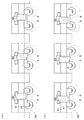
実行状態の時には、図3(a)に示すように、カムシャフト10及び回転部材20は、それらのストロークの左側にそれぞれ配されて、回転部材20の駆動用カム面23がロッカアーム50のローラ51に当接している。また、このとき、右駆動ピン33及び左駆動ピン38はそれらの先後方向のストロークの後側に配されている。その状態から、右駆動ピン33がその先方に右駆動用ソレノイド34によって駆動されて、該右駆動ピン33の先端面がカムシャフト10の右駆動用拡径部15の外周面に当接する。その状態から、カムシャフト10が回転して右駆動溝32の始端部32aが右駆動ピン33の先端部の先方にきた時に、図3(b)に示すように、該右駆動ピン33の先端部が該右駆動溝32の始端部32aに押し込まれ、該右駆動ピン33が該右駆動溝32に係合する。その状態から、更に、カムシャフト10が回転するのに従い、右駆動溝32の長さ方向中間部32bの右内側面が右駆動ピン33の先端部の右外側面に押圧されて、図3(c)に示すように、カムシャフト10が右方向に変位し、その後、右駆動溝32の終端部32cから該右駆動ピン33の先端部が押し出される。
{1} When switching from the running state to the resting state In the running state, as shown in FIG. 3A, the
このカムシャフト10の右方向への変位に伴い、同図3(c)に示すように、回転部材20も、右駆動用突起13によって右方向に押圧されて右方向に変位し、右案内溝41の始端部41aが、係合ピン43のカムシャフト10の周方向側に重なる位置に変位する。その状態からカムシャフト10が回転して、右案内溝41の始端部41aが係合ピン43の先端部の先方にきた時に、該係合ピン43の先端部がバネ45の復元力で該右案内溝41の始端部41aに押し込まれ、同図3(c)に示すように、該係合ピン43が該右案内溝41に係合する。その状態から、更に、カムシャフト10が回転するのに従い、図3(d)に示すように、右案内溝41の長さ方向中間部41bの右内側面が係合ピン43の先端部の右外側面に押圧されて、回転部材20がカムシャフト10に対して右方向に相対変位し、その後、右案内溝41の終端部41cから該係合ピン43の先端部が押し出される。
As the
そして、この状態から、更に、同図3(d)に示すように、変位用バネ48がカムシャフト10の外周面に設けられた湾曲面49の右部を左方向に押圧することによって、その反作用で、図3(e)に示すように、回転部材20がカムシャフト10に対して更に右方向に相対変位し、左駆動用突起14の左側面に該回転部材20の右側面が当接することによって該相対変位が止まる。これによって、右案内溝41及び左案内溝42は、係合ピン43とは係合不能な該係合ピン43の右方に変位する。
Then, from this state, as shown in FIG. 3D, the
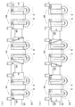
以上に示した一連の動作によって、図4(a)に示すように、一の回転部材20が、その駆動用カム面23でロッカアーム50のローラ51に当接するストロークの左側の実行位置から、休止用カム面24でロッカアーム50のローラ51に当接するストロークの右側の休止位置に変位し、それによって、該一の回転部材20に対応する一対のバルブ8,8の駆動状態が実行状態から休止状態に切り換わる。その一の回転部材20の右方向への変位に遅れて、図4(b)に示すように、別の回転部材20も同様に右方向に変位して、該別の回転部材20に対応する一対のバルブ8,8の駆動状態も、実行状態から休止状態に切り換わる。そして、更に、その別の回転部材20の変位に遅れて、図4(c)に示すように、残りの回転部材20も同様に右方向に変位して、該残りの回転部材20に対応するバルブ8,8の駆動状態も、実行状態から休止状態に切り換わる。
As a result of the series of operations described above, as shown in FIG. 4A, the one rotating
{2}休止状態から実行状態に切り換える際
この際は、上記{1}の際と、右を左に及び左を右に、駆動用カム面を休止用カム面に及び休止用カム面を駆動用カム面に、並びに実行状態を休止状態に及び休止状態を実行状態に、それぞれ読み替え、かつ、各部材の番号を、該読み替え後の部材名に対応する番号にそれぞれ読み替えるとともに、図に関する記載を削除して同様である。
{2} When switching from the resting state to the running state At this time, in the case of {1} above, the right is to the left and the left to the right, the driving cam surface is driven to the resting cam surface, and the resting cam surface is driven. In the cam surface, the execution state is changed to the dormant state and the dormant state is changed to the execution state, and the numbers of the respective members are replaced with the numbers corresponding to the member names after the replacement, and descriptions relating to the drawings It is the same with deleting.
本実施例によれば、変位量増幅機構40,40,40があるため、カムシャフト10を左右方向に、各駆動用カム面23,23,23及び各休止用カム面24,24,24を変位させたい長さ分未満の長さ分だけ変位させるだけで、図5(a)(b)に示すように、各駆動用カム面23,23,23及び各休止用カム面24,24,24を該変位させたい長さ分だけ変位させることができる。
According to the present embodiment, since there are the displacement
また、1本のカムシャフト10を1つの駆動機構30で左右方向に変位させるだけでよいので、各回転部材20,20,20毎に駆動機構を設ける必要がなく、それによって、可変動弁機構9の簡素化とコンパクト化とが図られている。また、それに加え、各回転部材20,20,20毎に駆動機構があれば、各駆動機構間での信号の乱れ等による足並みのずれで、エンジン不調に繋がるおそれもあるが、本実施例ではそのような心配もない。
Further, since it is only necessary to displace one
また、右案内溝41と左案内溝42とは、交差部Xで交差する交差状に設けられているため、これら2つの溝に対して1つの係合ピン43を設けるだけでよく、それによっても、可変動弁機構9の簡素化とコンパクト化とが図られている。また、その係合ピン43は、逸れ防止部43aを備えているため、該係合ピン43が交差部Xで、右案内溝41及び左案内溝42の一方から他方に逸れてしまう心配もない。
Further, since the
なお、本発明は上記実施例の構成に限定されるものではなく、発明の趣旨から逸脱しない範囲で変更して具体化することもでき、例えば、次の変更例1〜4のように変更してもよい。 The present invention is not limited to the configuration of the above embodiment, and can be modified and embodied without departing from the spirit of the invention. For example, the following modifications 1 to 4 can be made. May be.
[変更例1]
実施例では、バルブ8,8及びバルブスプリング60,60が3対ずつで、回転部材20、変位量増幅機構40及びロッカアーム50が3つずつの場合を示したが、それらの数は、特に限定されず、例えば、このように3対又は3つずつでなくても、4対又は4つずつ、5対又は5つずつ、6対又は6つずつ等であってもよい。
[Modification 1]
In the embodiment, a case is shown in which there are three pairs of the
[変更例2]
実施例では、ロッカアーム50が、一対のバルブ8,8を同時に駆動する2弁一体型のアームである場合を示したが、図6(a)に示すように、該ロッカアーム50を、一のバルブ8のみを駆動する一対のロッカアーム50,50に代え、各回転部材20に、該一対のロッカアーム50,50に当接する一対の駆動用カム面23,23と一対の休止用カム面24,24とを設けてもよい。
[Modification 2]
In the embodiment, the case where the
[変更例3]
実施例の図1〜図5には、カムシャフト10の回転方向が左側面視で右回りの場合を示したが、左回りの方がバルブ8,8・・の駆動が安定する場合等には、図6(b)に示すように、左回りにしてもよい。この場合には、右駆動溝32、左駆動溝37、右案内溝41及び左案内溝42の形状も、図1〜図5に示す形状とは、それぞれカムシャフト10の周方向に反対になる。
[Modification 3]
1 to 5 of the embodiment show the case where the rotation direction of the
[変更例4]
実施例の図1〜図5には、右駆動用拡径部15に一の右駆動溝32を設け、左駆動用拡径部16に一の左駆動溝37を設けた場合を示したが、図6(c)に示すように、右駆動用拡径部15に複数の右駆動溝32,32・・をカムシャフト10の周方向に並べて並設し、左駆動用拡径部16に複数の左駆動溝37,37・・をカムシャフト10の周方向に並べて並設してもよい。これらの溝の数は、多いほど、カムシャフト10の構造が複雑になってしまう一方、多いほど、より早いタイミングでカムシャフト10を左右方向に駆動して、より早いタイミングでバルブ8,8・・の駆動状態を切り換えることができる。
[Modification 4]
1 to 5 of the embodiment show a case where one
6 シリンダヘッド
8 バルブ
9 可変動弁機構
10 カムシャフト
20 回転部材
23 駆動用カム面
30 駆動機構
40 変位量増幅機構
41 右案内溝
42 左案内溝
43 係合ピン
43a 逸れ防止部
X 交差部
6
Claims (3)
前記カムシャフトに該カムシャフトの長さ方向に並べて該長さ方向に相対変位可能、該カムシャフトの周方向に相対変位不能にそれぞれ外挿され、外周面に、該カムシャフトと伴に回転するの従いバルブ(8)を駆動する少なくとも一種類の駆動用カム面(23)をそれぞれ備えた複数の回転部材(20)と、
前記カムシャフトを該カムシャフトの長さ方向に変位させる駆動機構(30)と、
各回転部材毎に設けられ、前記カムシャフトが該カムシャフトの長さ方向に変位すると、該カムシャフトの回転力を該カムシャフトの変位方向への変位力に変えて各回転部材に伝えて、該カムシャフトに対して各回転部材を該カムシャフトの変位方向に相対変位させる複数の変位量増幅機構(40)とを含み構成され、
前記カムシャフト(10)を前記駆動機構(30)で該カムシャフトの長さ方向に変位させ、該カムシャフトに対して各回転部材(20)を各変位量増幅機構(40)で該カムシャフトの変位方向に相対変位させることによって、各回転部材(20)が前記一種類の駆動用カム面(23)でバルブ(8)を駆動する状態と該一種類の駆動用カム面でバルブを駆動しない状態との間でバルブの駆動状態を変更する可変動弁機構。 A camshaft (10) that rotates in the circumferential direction in accordance with the rotation of the crankshaft and is displaceable in the length direction;
The camshaft is arranged in the lengthwise direction of the camshaft and is extrapolated so as to be relatively displaceable in the lengthwise direction and not to be relatively displaceable in the circumferential direction of the camshaft, and rotates on the outer peripheral surface together with the camshaft. A plurality of rotating members (20) each having at least one type of drive cam surface (23) for driving the valve (8) according to
A drive mechanism (30) for displacing the camshaft in the longitudinal direction of the camshaft;
Provided for each rotating member, when the camshaft is displaced in the length direction of the camshaft, the rotational force of the camshaft is changed to a displacement force in the displacement direction of the camshaft and transmitted to each rotating member, A plurality of displacement amount amplifying mechanisms (40) configured to relatively displace each rotating member in the displacement direction of the camshaft with respect to the camshaft;
The camshaft (10) is displaced in the length direction of the camshaft by the drive mechanism (30), and each rotating member (20) is moved by the displacement amount amplifying mechanism (40) with respect to the camshaft. By relative displacement in the displacement direction, each rotary member (20) drives the valve (8) with the one type of drive cam surface (23) and drives the valve with the one type of drive cam surface. A variable valve mechanism that changes the driving state of the valve between the non-operating state and the non-operating state.
前記回転部材の外周面に設けられて該外周面の周方向に延び、前記カムシャフトの回転方向に向かうに従い該カムシャフトの長さ方向一方にずれる一方の案内溝(41)と、
前記回転部材の外周面に設けられて該外周面の周方向に延び、前記カムシャフトの回転方向に向かうに従い該カムシャフトの長さ方向他方にずれて前記一方の案内溝と交差部(X)で交差する他方の案内溝(42)と、
前記カムシャフトを支持したシリンダヘッド(6)に設けられ、前記カムシャフトが該カムシャフトの長さ方向一方に変位すると、前記一方の案内溝に係合して前記回転部材を該カムシャフトの回転に従い該カムシャフトの長さ方向一方に変位させ、前記カムシャフトが該カムシャフトの長さ方向他方に変位すると、前記他方の案内溝に係合して前記回転部材を該カムシャフトの回転に従い該カムシャフトの長さ方向他方に変位させる係合ピン(43)とを含み構成された請求項1記載の可変動弁機構。 The displacement amount amplification mechanism (40)
One guide groove (41) provided on the outer peripheral surface of the rotating member and extending in the circumferential direction of the outer peripheral surface and deviating in one of the length directions of the camshaft as it goes in the rotational direction of the camshaft;
Provided on the outer peripheral surface of the rotating member, extends in the circumferential direction of the outer peripheral surface, and shifts to the other in the length direction of the camshaft toward the rotating direction of the camshaft and intersects with the one guide groove (X) The other guide groove (42) intersecting at
Provided in the cylinder head (6) supporting the camshaft, when the camshaft is displaced in one of the camshaft lengthwise directions, the camshaft engages with the one guide groove to rotate the rotating member of the camshaft. When the camshaft is displaced to one side in the longitudinal direction of the camshaft, and the camshaft is displaced to the other in the longitudinal direction of the camshaft, the camshaft is engaged with the other guide groove and the rotating member is moved according to the rotation of the camshaft. The variable valve mechanism according to claim 1, further comprising an engagement pin (43) that is displaced in the other longitudinal direction of the camshaft.
Priority Applications (1)
| Application Number | Priority Date | Filing Date | Title |
|---|---|---|---|
| JP2008268016A JP5153562B2 (en) | 2008-10-16 | 2008-10-16 | Variable valve mechanism |
Applications Claiming Priority (1)
| Application Number | Priority Date | Filing Date | Title |
|---|---|---|---|
| JP2008268016A JP5153562B2 (en) | 2008-10-16 | 2008-10-16 | Variable valve mechanism |
Publications (2)
| Publication Number | Publication Date |
|---|---|
| JP2010096102A true JP2010096102A (en) | 2010-04-30 |
| JP5153562B2 JP5153562B2 (en) | 2013-02-27 |
Family
ID=42257957
Family Applications (1)
| Application Number | Title | Priority Date | Filing Date |
|---|---|---|---|
| JP2008268016A Expired - Fee Related JP5153562B2 (en) | 2008-10-16 | 2008-10-16 | Variable valve mechanism |
Country Status (1)
| Country | Link |
|---|---|
| JP (1) | JP5153562B2 (en) |
Cited By (7)
| Publication number | Priority date | Publication date | Assignee | Title |
|---|---|---|---|---|
| JP2010223081A (en) * | 2009-03-23 | 2010-10-07 | Toyota Motor Corp | Control device of variable valve mechanism |
| WO2012110069A1 (en) * | 2011-02-17 | 2012-08-23 | Daimler Ag | Camshaft with axially movable cam elements |
| JP2013155709A (en) * | 2012-01-31 | 2013-08-15 | Daihatsu Motor Co Ltd | Internal combustion engine |
| KR101427958B1 (en) * | 2012-12-18 | 2014-08-11 | 현대자동차 주식회사 | Mutiple variable valve lift appratus and engine provided with the same |
| KR101448778B1 (en) | 2013-03-08 | 2014-10-13 | 현대자동차 주식회사 | Mutiple variable valve lift appratus |
| KR101461890B1 (en) | 2013-03-14 | 2014-11-14 | 현대자동차 주식회사 | Mutiple variable valve lift appratus, mutiple variable valve lift system and engine provided with the same |
| JP2016070164A (en) * | 2014-09-30 | 2016-05-09 | マツダ株式会社 | Cylinder head for vehicle-mounted engine |
Citations (8)
| Publication number | Priority date | Publication date | Assignee | Title |
|---|---|---|---|---|
| JPS5244314A (en) * | 1975-10-06 | 1977-04-07 | Mitsubishi Motors Corp | Variable valve-timing device |
| JPH06212924A (en) * | 1993-01-20 | 1994-08-02 | Otix:Kk | Variable valve mechanism |
| JPH06221122A (en) * | 1993-01-29 | 1994-08-09 | Mazda Motor Corp | Valve timing control device for engine |
| JPH108928A (en) * | 1996-03-25 | 1998-01-13 | Dr Ing H C F Porsche Ag | Valve driving device for internal combustion engine |
| JP2005042717A (en) * | 2003-07-19 | 2005-02-17 | Dr Ing H C F Porsche Ag | Valve drive mechanism for internal combustion engine |
| JP2006170188A (en) * | 2004-12-17 | 2006-06-29 | Hyundai Motor Co Ltd | Variable cam system |
| JP2006520869A (en) * | 2003-03-21 | 2006-09-14 | アウディー アーゲー | Valve mechanism for internal combustion engine with cylinder head |
| WO2008107111A1 (en) * | 2007-03-02 | 2008-09-12 | Audi Ag | Valve drive for gas exchange valves of an internal combustion engine, comprising a movable cam support and a twin worm gear |
-
2008
- 2008-10-16 JP JP2008268016A patent/JP5153562B2/en not_active Expired - Fee Related
Patent Citations (8)
| Publication number | Priority date | Publication date | Assignee | Title |
|---|---|---|---|---|
| JPS5244314A (en) * | 1975-10-06 | 1977-04-07 | Mitsubishi Motors Corp | Variable valve-timing device |
| JPH06212924A (en) * | 1993-01-20 | 1994-08-02 | Otix:Kk | Variable valve mechanism |
| JPH06221122A (en) * | 1993-01-29 | 1994-08-09 | Mazda Motor Corp | Valve timing control device for engine |
| JPH108928A (en) * | 1996-03-25 | 1998-01-13 | Dr Ing H C F Porsche Ag | Valve driving device for internal combustion engine |
| JP2006520869A (en) * | 2003-03-21 | 2006-09-14 | アウディー アーゲー | Valve mechanism for internal combustion engine with cylinder head |
| JP2005042717A (en) * | 2003-07-19 | 2005-02-17 | Dr Ing H C F Porsche Ag | Valve drive mechanism for internal combustion engine |
| JP2006170188A (en) * | 2004-12-17 | 2006-06-29 | Hyundai Motor Co Ltd | Variable cam system |
| WO2008107111A1 (en) * | 2007-03-02 | 2008-09-12 | Audi Ag | Valve drive for gas exchange valves of an internal combustion engine, comprising a movable cam support and a twin worm gear |
Cited By (9)
| Publication number | Priority date | Publication date | Assignee | Title |
|---|---|---|---|---|
| JP2010223081A (en) * | 2009-03-23 | 2010-10-07 | Toyota Motor Corp | Control device of variable valve mechanism |
| WO2012110069A1 (en) * | 2011-02-17 | 2012-08-23 | Daimler Ag | Camshaft with axially movable cam elements |
| US8997706B2 (en) | 2011-02-17 | 2015-04-07 | Daimler Ag | Internal combustion engine valve actuation control arrangement |
| JP2013155709A (en) * | 2012-01-31 | 2013-08-15 | Daihatsu Motor Co Ltd | Internal combustion engine |
| KR101427958B1 (en) * | 2012-12-18 | 2014-08-11 | 현대자동차 주식회사 | Mutiple variable valve lift appratus and engine provided with the same |
| US9074499B2 (en) | 2012-12-18 | 2015-07-07 | Hyundai Motor Company | Multiple variable valve lift apparatus and engine provided with the same |
| KR101448778B1 (en) | 2013-03-08 | 2014-10-13 | 현대자동차 주식회사 | Mutiple variable valve lift appratus |
| KR101461890B1 (en) | 2013-03-14 | 2014-11-14 | 현대자동차 주식회사 | Mutiple variable valve lift appratus, mutiple variable valve lift system and engine provided with the same |
| JP2016070164A (en) * | 2014-09-30 | 2016-05-09 | マツダ株式会社 | Cylinder head for vehicle-mounted engine |
Also Published As
| Publication number | Publication date |
|---|---|
| JP5153562B2 (en) | 2013-02-27 |
Similar Documents
| Publication | Publication Date | Title |
|---|---|---|
| JP5153562B2 (en) | Variable valve mechanism | |
| JP4476241B2 (en) | Valve operating device for internal combustion engine | |
| JP6059080B2 (en) | Variable valve mechanism for internal combustion engine | |
| US7661400B2 (en) | Switchable cam follower | |
| JP5066504B2 (en) | Internal combustion engine and motorcycle with variable valve gear | |
| US20080230023A1 (en) | Variable valve mechanism | |
| JP4813399B2 (en) | Variable valve mechanism | |
| JP2008025418A (en) | Variable valve train of internal combustion engine | |
| JP2013133809A (en) | Variable valve train | |
| JP4931621B2 (en) | Variable valve mechanism for internal combustion engine | |
| JP2018044534A (en) | Variable valve mechanism of internal combustion engine | |
| JP6233386B2 (en) | Variable valve mechanism | |
| JP2018009467A (en) | Variable valve mechanism | |
| JP6546855B2 (en) | Variable valve mechanism of internal combustion engine | |
| JP6265945B2 (en) | Variable valve mechanism for internal combustion engine | |
| JP2009264199A (en) | Variable valve gear | |
| JP7101624B2 (en) | Variable valve mechanism of internal combustion engine | |
| JP2009209847A (en) | Variable valve train | |
| JP2018084197A (en) | Variable valve mechanism of internal combustion engine | |
| JP5359332B2 (en) | Variable valve operating device for internal combustion engine | |
| JP2013096344A (en) | Variable valve mechanism | |
| JP5510095B2 (en) | Variable valve operating device for internal combustion engine | |
| JP2008190392A (en) | Variable valve train | |
| JP2007113435A (en) | Variable valve gear of internal combustion engine | |
| EP3346102B1 (en) | Variable valve mechanism of internal combustion engine |
Legal Events
| Date | Code | Title | Description |
|---|---|---|---|
| A621 | Written request for application examination |
Free format text: JAPANESE INTERMEDIATE CODE: A621 Effective date: 20110907 |
|
| A977 | Report on retrieval |
Free format text: JAPANESE INTERMEDIATE CODE: A971007 Effective date: 20121108 |
|
| TRDD | Decision of grant or rejection written | ||
| A01 | Written decision to grant a patent or to grant a registration (utility model) |
Free format text: JAPANESE INTERMEDIATE CODE: A01 Effective date: 20121120 |
|
| A61 | First payment of annual fees (during grant procedure) |
Free format text: JAPANESE INTERMEDIATE CODE: A61 Effective date: 20121204 |
|
| FPAY | Renewal fee payment (event date is renewal date of database) |
Free format text: PAYMENT UNTIL: 20151214 Year of fee payment: 3 |
|
| R150 | Certificate of patent or registration of utility model |
Ref document number: 5153562 Country of ref document: JP Free format text: JAPANESE INTERMEDIATE CODE: R150 Free format text: JAPANESE INTERMEDIATE CODE: R150 |
|
| R250 | Receipt of annual fees |
Free format text: JAPANESE INTERMEDIATE CODE: R250 |
|
| R250 | Receipt of annual fees |
Free format text: JAPANESE INTERMEDIATE CODE: R250 |
|
| R250 | Receipt of annual fees |
Free format text: JAPANESE INTERMEDIATE CODE: R250 |
|
| R250 | Receipt of annual fees |
Free format text: JAPANESE INTERMEDIATE CODE: R250 |
|
| R250 | Receipt of annual fees |
Free format text: JAPANESE INTERMEDIATE CODE: R250 |
|
| R250 | Receipt of annual fees |
Free format text: JAPANESE INTERMEDIATE CODE: R250 |
|
| LAPS | Cancellation because of no payment of annual fees |