JP2010093940A - Power supply circuit and signal detection apparatus - Google Patents
Power supply circuit and signal detection apparatus Download PDFInfo
- Publication number
- JP2010093940A JP2010093940A JP2008261010A JP2008261010A JP2010093940A JP 2010093940 A JP2010093940 A JP 2010093940A JP 2008261010 A JP2008261010 A JP 2008261010A JP 2008261010 A JP2008261010 A JP 2008261010A JP 2010093940 A JP2010093940 A JP 2010093940A
- Authority
- JP
- Japan
- Prior art keywords
- signal
- power supply
- line
- power
- signal detector
- Prior art date
- Legal status (The legal status is an assumption and is not a legal conclusion. Google has not performed a legal analysis and makes no representation as to the accuracy of the status listed.)
- Granted
Links
Images

Classifications
-
- B—PERFORMING OPERATIONS; TRANSPORTING
- B62—LAND VEHICLES FOR TRAVELLING OTHERWISE THAN ON RAILS
- B62D—MOTOR VEHICLES; TRAILERS
- B62D6/00—Arrangements for automatically controlling steering depending on driving conditions sensed and responded to, e.g. control circuits
- B62D6/08—Arrangements for automatically controlling steering depending on driving conditions sensed and responded to, e.g. control circuits responsive only to driver input torque
- B62D6/10—Arrangements for automatically controlling steering depending on driving conditions sensed and responded to, e.g. control circuits responsive only to driver input torque characterised by means for sensing or determining torque
-
- B—PERFORMING OPERATIONS; TRANSPORTING
- B62—LAND VEHICLES FOR TRAVELLING OTHERWISE THAN ON RAILS
- B62D—MOTOR VEHICLES; TRAILERS
- B62D5/00—Power-assisted or power-driven steering
- B62D5/04—Power-assisted or power-driven steering electrical, e.g. using an electric servo-motor connected to, or forming part of, the steering gear
- B62D5/0457—Power-assisted or power-driven steering electrical, e.g. using an electric servo-motor connected to, or forming part of, the steering gear characterised by control features of the drive means as such
- B62D5/0481—Power-assisted or power-driven steering electrical, e.g. using an electric servo-motor connected to, or forming part of, the steering gear characterised by control features of the drive means as such monitoring the steering system, e.g. failures
- B62D5/0484—Power-assisted or power-driven steering electrical, e.g. using an electric servo-motor connected to, or forming part of, the steering gear characterised by control features of the drive means as such monitoring the steering system, e.g. failures for reaction to failures, e.g. limp home
-
- B—PERFORMING OPERATIONS; TRANSPORTING
- B62—LAND VEHICLES FOR TRAVELLING OTHERWISE THAN ON RAILS
- B62D—MOTOR VEHICLES; TRAILERS
- B62D5/00—Power-assisted or power-driven steering
- B62D5/04—Power-assisted or power-driven steering electrical, e.g. using an electric servo-motor connected to, or forming part of, the steering gear
- B62D5/0457—Power-assisted or power-driven steering electrical, e.g. using an electric servo-motor connected to, or forming part of, the steering gear characterised by control features of the drive means as such
- B62D5/0481—Power-assisted or power-driven steering electrical, e.g. using an electric servo-motor connected to, or forming part of, the steering gear characterised by control features of the drive means as such monitoring the steering system, e.g. failures
- B62D5/049—Power-assisted or power-driven steering electrical, e.g. using an electric servo-motor connected to, or forming part of, the steering gear characterised by control features of the drive means as such monitoring the steering system, e.g. failures detecting sensor failures
Landscapes
- Engineering & Computer Science (AREA)
- Chemical & Material Sciences (AREA)
- Combustion & Propulsion (AREA)
- Transportation (AREA)
- Mechanical Engineering (AREA)
- Testing Of Short-Circuits, Discontinuities, Leakage, Or Incorrect Line Connections (AREA)
- Power Steering Mechanism (AREA)
- Direct Current Feeding And Distribution (AREA)
- Control Of Voltage And Current In General (AREA)
Abstract
Description
本発明は、電源から負荷に電力を供給する電力供給回路及び電力供給回路を用いた信号検出装置に関するものである。 The present invention relates to a power supply circuit that supplies power from a power supply to a load, and a signal detection device using the power supply circuit.
電力供給回路や信号検出装置においては、断線等の事態に備えて、配線を2系統・3系統といったように複数系統の配線に同じ機能を持たせ、複数系統のうち一部が断線した後にも、電力供給回路や信号検出装置を稼動させることが一般に行われている(例えば、特許文献1参照)。
ところで、電源ラインの故障としては断線故障の他に、接地部分以外において電源ラインと大地が電気的に接続され、電源ラインと大地の間に電流が流れる地絡故障があげられる。 By the way, as a failure of the power supply line, in addition to the disconnection failure, there is a ground fault where the power supply line and the ground are electrically connected at a portion other than the ground portion and a current flows between the power supply line and the ground.
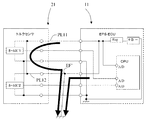
例えば、図6に示すように、ホールIC1が電源ラインPL11と電源ラインPL12との2系統の電源ラインから電力の供給を受けている場合、電源ラインPL12のEF’点が大地と電気的に接続(地絡)されると、電源ラインPL12に流れる電流は地絡地点であるEF’点を介して大地に向かって電流が流れてしまう。その上、ホールIC1に電力を供給する関係から電源ラインPL11と電源ラインPL12とは電気的に繋がっているため、電源ラインPL11を流れる電流は矢印の方向に流れる。この結果、電源ラインPL12を流れる電流も地絡地点EPを介して大地に向かって流れてしまう。 For example, as shown in FIG. 6, when the Hall IC 1 is supplied with power from two power supply lines of the power supply line PL11 and the power supply line PL12, the EF ′ point of the power supply line PL12 is electrically connected to the ground. When a (ground fault) occurs, the current flowing through the power supply line PL12 flows toward the ground via the EF ′ point which is the ground fault point. In addition, since the power supply line PL11 and the power supply line PL12 are electrically connected from the relationship of supplying power to the Hall IC 1, the current flowing through the power supply line PL11 flows in the direction of the arrow. As a result, the current flowing through the power supply line PL12 also flows toward the ground via the ground fault point EP.
このように、電源ラインを複数系統にした電力供給回路や信号検出装置においては、複数系統が電気的に導通しているため、1系統に地絡がおきると、地絡の影響が他の系統に及んでしまう問題があった。 As described above, in the power supply circuit and the signal detection device in which the power supply line has a plurality of systems, the plurality of systems are electrically connected. Therefore, when a ground fault occurs in one system, the influence of the ground fault is caused by another system. There was a problem that extended to.
本発明は上記問題点に鑑みたものであり、その目的は、電源ラインを複数系統にした電力供給回路や信号検出装置において、1系統に生じた地絡が他の系統に及ぶことを防ぐことができる電力供給回路及び信号検出装置を提供することにある。 The present invention has been made in view of the above problems, and its purpose is to prevent a ground fault occurring in one system from reaching another system in a power supply circuit or signal detection device having a plurality of power supply lines. An object of the present invention is to provide a power supply circuit and a signal detection device that can perform the above.
請求項1記載の発明では、電源と、電源に並列接続された第1負荷及び第2負荷と、電源と第1負荷を接続する第1電源ラインと、電源と第2負荷を接続する第2電源ラインと、第1電源ラインと第2電源ラインのうちいずれか一方の電源ラインが断線した場合でも第1負荷及び第2負荷が他方の電源ラインから電力供給を受けることができるように第1電源ラインと第2電源ラインを接続した電源ライン接続部と、を有し、第1電源ライン及び第2電源ラインは、それぞれ電源ライン接続部と電源との間に電源から負荷に流れる電流のみ通電して逆方向に流れる電流を遮断する整流素子を設けたことを特徴とする。 According to the first aspect of the present invention, the power source, the first load and the second load connected in parallel to the power source, the first power line connecting the power source and the first load, and the second connecting the power source and the second load. The first load and the second load can receive power from the other power supply line even when one of the power supply line, the first power supply line, and the second power supply line is disconnected. A power supply line connecting portion connecting the power supply line and the second power supply line, and the first power supply line and the second power supply line energize only the current flowing from the power supply to the load between the power supply line connecting portion and the power supply, respectively. Thus, a rectifying element that cuts off the current flowing in the reverse direction is provided.
上記構成では、整流素子が、第1電源ライン又は第2電源ラインの一方の電源ラインから電源ライン接続部を介して第1電源ライン又は第2電源ラインの他方の電源ラインに流れる短絡電流を遮断するため、第1電源ライン又は第2電源ラインの一方の電源ラインが地絡したとしても、他方の電源ラインを介して電源から第1負荷及び第2負荷に電力を供給し続けることができる。 In the above configuration, the rectifying element cuts off a short-circuit current flowing from one power line of the first power line or the second power line to the other power line of the first power line or the second power line via the power line connecting portion. Therefore, even if one power supply line of the first power supply line or the second power supply line is grounded, power can be continuously supplied from the power supply to the first load and the second load via the other power supply line.
請求項2記載の発明では、第1電源ライン及び第2電源ラインは、それぞれ整流素子と電源との間に入力電力を所定の出力電力に変換するレギュレータを有することを特徴とする。 According to a second aspect of the present invention, each of the first power supply line and the second power supply line includes a regulator that converts input power into predetermined output power between the rectifier element and the power supply.
第1電源ラインと第2電源ラインとがレギュレータを共用すると、一方の電源ラインが地絡して短絡電流が流れてレギュレータが破壊されると、他方の電源ラインもレギュレータを用いることができなくなる。一方、上記構成では、レギュレータを第1電源ライン及び第2電源ラインそれぞれに設けているため、第1電源ライン又は第2電源ラインの一方の電源ラインが地絡して短絡電流が流れて、地絡した電源ラインのレギュレータが破壊されたとしても、他方の電源ラインのレギュレータは無事であり、そのまま電力変換を行うことができる。 If the first power supply line and the second power supply line share the regulator, when one power supply line is grounded and a short-circuit current flows and the regulator is destroyed, the other power supply line cannot use the regulator. On the other hand, in the above configuration, since the regulator is provided in each of the first power supply line and the second power supply line, one power supply line of the first power supply line or the second power supply line is grounded, and a short-circuit current flows. Even if the tangled power supply line regulator is destroyed, the other power supply line regulator is safe and can perform power conversion as it is.
請求項3記載の発明では、所定の対象を検出して第1信号を出力する第1信号検出器と、所定の対象を検出して第2信号を出力する第2信号検出器と、第1信号検出器と第2信号検出器とに並列接続される電源と、電源と第1信号検出器を接続する第1電源ラインと、電源と第2信号検出器を接続する第2電源ラインと、第1信号を伝達する第1信号ラインと、第2信号を伝達する第2信号ラインと、第1信号ライン及び第2信号ラインを介して第1信号と第2信号とを検出する信号検出回路と、第1電源ラインと第2電源ラインのうちいずれか一方の電源ラインが断線した場合でも第1信号検出器及び第2信号検出器が他方の電源ラインから電力供給を受けることができるように第1電源ラインと第2電源ラインを接続した電源ライン接続部と、を有し、第1電源ライン及び第2電源ラインは、それぞれ電源ライン接続部と電源との間に電源から信号検出器に流れる電流のみ通電して逆方向に流れる電流を遮断する整流素子を設けることを特徴とする。 According to a third aspect of the present invention, a first signal detector that detects a predetermined target and outputs a first signal, a second signal detector that detects a predetermined target and outputs a second signal, A power supply connected in parallel to the signal detector and the second signal detector; a first power supply line connecting the power supply and the first signal detector; a second power supply line connecting the power supply and the second signal detector; A signal detection circuit for detecting a first signal and a second signal via a first signal line for transmitting a first signal, a second signal line for transmitting a second signal, and the first signal line and the second signal line The first signal detector and the second signal detector can receive power from the other power line even when one of the first power line and the second power line is disconnected. Power line connection that connects the first power line and the second power line The first power supply line and the second power supply line each have a rectifying element that cuts off the current flowing in the reverse direction by passing only the current flowing from the power supply to the signal detector between the power supply line connecting portion and the power supply. It is characterized by providing.
上記構成では、電源ライン接続部が、第1電源ライン又は第2電源ラインの一方の電源ラインから第1電源ライン又は第2電源ラインの他方の電源ラインに流れる短絡電流を遮断するため、第1電源ライン又は第2電源ラインの一方の電源ラインが地絡したとしても、他方の電源ラインを介して電源から第1信号検出器及び第2信号検出器に電力を供給し続けることができる。この結果、第1電源ライン又は第2電源ラインのいずれか一方が地絡しても、他方の電源ラインを用いて第1信号検出器及び第2信号検出器に電力を供給でき、第1信号検出器及び第2信号検出器は信号検出回路に信号を伝達することができる。 In the above configuration, the power supply line connecting section cuts off the short-circuit current flowing from one power supply line of the first power supply line or the second power supply line to the other power supply line of the first power supply line or the second power supply line. Even if one power supply line of the power supply line or the second power supply line is grounded, power can be continuously supplied from the power supply to the first signal detector and the second signal detector via the other power supply line. As a result, even if either the first power supply line or the second power supply line is grounded, power can be supplied to the first signal detector and the second signal detector using the other power supply line. The detector and the second signal detector can transmit a signal to the signal detection circuit.
請求項4記載の発明では、第1電源ライン及び第2電源ラインは、それぞれ整流素子と電源との間に入力電力を所定の出力電力に変換するレギュレータを有することを特徴とする。 According to a fourth aspect of the present invention, each of the first power supply line and the second power supply line includes a regulator that converts input power into predetermined output power between the rectifying element and the power supply.
第1電源ラインと第2電源ラインとがレギュレータを共用すると、一方の電源ラインが地絡して短絡電流が流れてレギュレータが破壊されると、他方の電源ラインもレギュレータを用いることができなくなる。一方、上記構成では、レギュレータを第1電源ライン及び第2電源ラインそれぞれに設けているため、第1電源ライン又は第2電源ラインの一方の電源ラインが地絡して短絡電流が流れて、地絡した電源ラインのレギュレータが破壊されたとしても、他方の電源ラインのレギュレータは無事であり、そのまま電力変換を行うことができる。 If the first power supply line and the second power supply line share the regulator, when one power supply line is grounded and a short-circuit current flows and the regulator is destroyed, the other power supply line cannot use the regulator. On the other hand, in the above configuration, since the regulator is provided in each of the first power supply line and the second power supply line, one power supply line of the first power supply line or the second power supply line is grounded, and a short-circuit current flows. Even if the tangled power supply line regulator is destroyed, the other power supply line regulator is safe and can perform power conversion as it is.
請求項5記載の発明では、第1信号と第2信号とは、互いに位相反転の関係にあることを特徴とする。 The invention according to claim 5 is characterized in that the first signal and the second signal have a phase inversion relationship with each other.
第1信号ラインと第2信号ラインとで同じ信号を送信すると、単に信号を送信していない状況と断線している状況とを区別できない場合が現れる。一方、上記構成では、第1信号と第2信号とを位相反転させた場合には、信号検出回路が両信号が位相反転の関係にあるか否かを判定することで、信号ラインの断線等の異常が発生しているか否かを判定することができる。 If the same signal is transmitted on the first signal line and the second signal line, there may be a case where it is not possible to distinguish between a situation where no signal is being transmitted and a situation where the signal is disconnected. On the other hand, in the above configuration, when the first signal and the second signal are phase-inverted, the signal detection circuit determines whether or not both signals are in a phase-inverted relationship, thereby breaking the signal line, etc. It can be determined whether or not an abnormality has occurred.
請求項6記載の発明では、所定の対象を検出して第1信号を出力する第1信号検出器と、所定の対象を検出して第2信号を出力する第2信号検出器と、所定の対象を検出して第3信号を出力する第3信号検出器と、第1信号検出器と第2信号検出器と第3信号検出器とに並列接続される電源と、電源と第1信号検出器を接続する第1電源ラインと、電源と第2信号検出器を接続する第2電源ラインと、第1電源ライン又は第2電源ラインと第3信号検出器を接続する第3電源ラインと、第1信号を伝達する第1信号ラインと、第2信号を伝達する第2信号ラインと、第3信号を伝達する第3信号ラインと、第1信号ライン、第2信号ライン及び第3信号ラインを介して第1信号、第2信号及び第3信号を検出する信号検出回路と、第1電源ラインと第2電源ラインのうちいずれか一方の電源ラインが断線した場合でも第1信号検出器及び第2信号検出器が他方の電源ラインから電力供給を受けることができるように第1電源ラインと第2電源ラインを接続した電源ライン接続部と、を有し、第1電源ライン及び第2電源ラインは、それぞれ電源ライン接続部と電源との間に電源から信号検出器に流れる電流のみ通電して逆方向に流れる電流を遮断する整流素子を設け、第3電源ラインは、整流素子と第1信号検出器の間又は整流素子と第2信号検出器との間において、第1電源ライン又は第2電源ラインと接続されることを特徴とする。 In a sixth aspect of the invention, a first signal detector that detects a predetermined target and outputs a first signal, a second signal detector that detects a predetermined target and outputs a second signal, and a predetermined signal A third signal detector for detecting a target and outputting a third signal; a power source connected in parallel to the first signal detector, the second signal detector and the third signal detector; a power source and a first signal detection A first power supply line for connecting the power supply, a second power supply line for connecting the power supply and the second signal detector, a third power supply line for connecting the first power supply line or the second power supply line and the third signal detector, A first signal line for transmitting a first signal; a second signal line for transmitting a second signal; a third signal line for transmitting a third signal; a first signal line, a second signal line and a third signal line; A signal detection circuit for detecting the first signal, the second signal, and the third signal via the first power supply circuit; The first power supply line and the second power supply line so that the first signal detector and the second signal detector can receive power from the other power supply line even when one of the power supply lines is disconnected. A power supply line connecting portion connected to the second power supply line, and the first power supply line and the second power supply line energize only the current flowing from the power supply to the signal detector between the power supply line connecting portion and the power supply, respectively. The third power supply line is provided between the rectifying element and the first signal detector or between the rectifying element and the second signal detector. It is connected to two power lines.
上記構成によれば、第3信号検出器は第1電源ライン及び第2電源ラインを介して電力の供給を受けることができるため、第1電源ライン及び第2電源ラインを利用している分、第3電源ラインの長さを必要最小限にでき、かつ、並列接続する負荷の数だけ整流素子を設けずに済む。 According to the above configuration, since the third signal detector can receive power supply through the first power supply line and the second power supply line, the first power supply line and the second power supply line are used. The length of the third power supply line can be minimized, and it is not necessary to provide rectifying elements by the number of loads connected in parallel.
請求項7記載の発明では、第1信号検出器、第2信号検出器及び第3信号検出器をそれぞれ並列に接続する第1グランドラインと、第1信号検出器、第2信号検出器及び第3信号検出器をそれぞれ並列に接続する第2グランドラインと、を有し、第1信号検出器、第2信号検出器及び第3信号検出器は、第1グランドライン又は第2グランドラインの一方のグランドラインが断線しても他方のグランドラインにより接地されることを特徴とする。 According to the seventh aspect of the present invention, a first ground line for connecting the first signal detector, the second signal detector, and the third signal detector in parallel, the first signal detector, the second signal detector, and the first signal detector, respectively. A second ground line that connects the three signal detectors in parallel, and the first signal detector, the second signal detector, and the third signal detector are either the first ground line or the second ground line. Even if one of the ground lines is disconnected, the other ground line is grounded.
第1信号検出器、第2信号検出器及び第3信号検出器は、2系統のグランドラインをそれぞれ共用しているため、配線を減らすことができる。つまり、並列接続する負荷の数だけグランドラインを設けずに済む。 Since the first signal detector, the second signal detector, and the third signal detector share the two systems of ground lines, wiring can be reduced. That is, it is not necessary to provide ground lines as many as the number of loads connected in parallel.
請求項8記載の発明では、第1信号検出器と第2信号検出器と第3信号検出器と電源ライン接続部と整流素子とを収容する第1筐体と、電源と信号検出回路を収容する第2筐体と、を有することを特徴とする。 According to the eighth aspect of the present invention, the first housing for housing the first signal detector, the second signal detector, the third signal detector, the power line connecting portion and the rectifying element, the power source and the signal detecting circuit are housed. And a second housing.
上記構成では、第1筐体と第2筐体との間に位置する配線は、筐体に覆われていないため、筐体内と比べて相対的に地絡故障等の影響を受けやすいが、整流素子は第1信号検出器、第2信号検出器及び第3信号検出器が収容される第1筐体に収容されているため、第1筐体と第2筐体との間において、電源ラインに地絡が生じたとしても、その地絡の影響は他の電源ラインには影響を及ぼすことはない。 In the above configuration, since the wiring located between the first housing and the second housing is not covered by the housing, it is relatively susceptible to ground faults and the like compared to the inside of the housing, Since the rectifying element is housed in the first housing in which the first signal detector, the second signal detector, and the third signal detector are housed, a power source is provided between the first housing and the second housing. Even if a ground fault occurs in the line, the influence of the ground fault does not affect other power supply lines.
特に、地絡や断線といった不具合に耐性がある上記信号検出装置は、請求項9記載の発明のように、操舵トルクに基づいて車両のステアリングの操舵力を補助する電動パワーステアリング装置に用い、第1信号検出器、第2信号検出器及び第3信号検出器はそれぞれステアリングに作用する操舵トルクを検出するホールICである場合に好適である。 In particular, the signal detection device that is resistant to problems such as ground faults and disconnections is used in an electric power steering device that assists the steering force of the vehicle steering based on the steering torque, as in the ninth aspect of the invention. The 1 signal detector, the second signal detector, and the third signal detector are each suitable for a Hall IC that detects a steering torque acting on the steering.
請求項10記載の発明では、電源は車両のボディに接地されるものであって、第1信号検出器、第2信号検出器及び第3信号検出器は、第1グランドライン又は第2グランドラインに代えて、車両のボディに接地されることを特徴とする。 In the tenth aspect of the present invention, the power source is grounded to the vehicle body, and the first signal detector, the second signal detector, and the third signal detector are the first ground line or the second ground line. Instead, it is characterized in that it is grounded to the vehicle body.
上記構成では、第1グランドライン又は第2グランドラインの代わりに、車両のボディに接地しているため、グランドラインの数を減らすことができる。 In the above configuration, the number of ground lines can be reduced since the vehicle is grounded instead of the first ground line or the second ground line.
以下、本発明をモータ(図示せず)の駆動力をステアリングのアシストに用いる電動式パワーステアリング装置(EPS)の信号検出装置1に用いた場合の実施形態について説明する。
Hereinafter, an embodiment in which the present invention is used for a
(実施例1)
(全体構成)
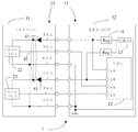
図1に実施例1に係る信号検出装置1のシステム構成図を示す。信号検出装置1は、主にトルクセンサ21と、EPS−ECU11とからなる。トルクセンサ21はステアリング(図示せず)の操舵トルクを検出し、EPS−ECU11は、操舵トルクに基づいて、ステアリングの操舵力をアシストするべくモータを制御する。
Example 1
(overall structure)
FIG. 1 shows a system configuration diagram of a
トルクセンサ21とEPS−ECU11とは、電源ラインPL1〜PL3、信号ラインSL1〜SL3及びグランドラインGL1〜GL2によって接続されている。
なお、電源である電源回路13と、第1負荷(第1信号検出器)22であるホールIC1及び第2負荷(第2信号検出器)23であるホールIC2と、第1電源ラインPL1と、第2電源ラインPL2と、電源ライン接続部42と、整流素子41は、電力供給回路を構成する。
The
(トルクセンサ)
トルクセンサ21は、車両のステアリングに作用する操舵トルクを検出し、その検出した操舵トルクに対応するトルク信号を第1信号ラインSL1及び第2信号ラインSL2を介してEPS−ECU11側に送信する。トルクセンサ21は、第1筐体31内部に第1負荷(第1信号検出器22)であるホールIC1と第2負荷(第2信号検出器23)であるホールIC2とを有する。
(Torque sensor)
The
(EPS−ECU)
EPS−ECU11は、第2筐体32内部に電源である電源回路13と、レギュレータ14と、信号検出回路であるCPU12とを有する。電源回路13は、車両のボディに接地(ボディアース)されるものであり、電源ラインを介して、トルクセンサ21に電力を供給する。レギュレータ14は、電源回路13から出力する電圧・電流を一定に保つために用いられる。CPU12は、トルクセンサ21側から送信されたトルク信号を受け取り、モータの制御に必要な演算を行う。
(EPS-ECU)
The EPS-
(電源ライン)
第1電源ラインPL1は、電源回路13とホールIC1とを接続し、第2電源ラインPL2は、電源回路13とホールIC2を接続する。電源ライン接続部42は、第1電源ラインPL1と第2電源ラインPL2とを接続する。電源ライン接続部42を介することで、第1電源ラインPL1と第2電源ラインPL2のうちいずれか一方の電源ラインが断線した場合でもホールIC1及びホールIC2が他方の電源ラインから電力供給を受けることができる。
(Power line)
The first power supply line PL1 connects the
(整流素子)
整流素子41は、第1電源ラインPL1と第2電源ラインPL2それぞれに設けられ、電源ライン接続部42と電源回路13との間に電源回路13からホールICに流れる電流のみ通電して逆方向に流れる電流を遮断する。
(Rectifier element)
The rectifying
つまり、電源ライン接続部42が、第1電源ラインPL1又は第2電源ラインPL2の一方の電源ラインから第1電源ラインPL1又は第2電源ラインPL2の他方の電源ラインに流れる短絡電流を遮断するため、第1電源ラインPL1又は第2電源ラインPL2の一方の電源ラインが地絡したとしても、他方の電源ラインを介して電源回路13からホールIC1、ホールIC2及びホールIC3に電力を供給し続けることができる。この結果、第1電源ラインPL1又は第2電源ラインPL2のいずれか一方が地絡しても、他方の電源ラインを用いてホールIC1、ホールIC2及びホールIC3に電力を供給でき、ホールIC1、ホールIC2及びホールIC3は信号検出回路に信号を伝達することができる。
That is, the power supply
図1の例では、整流素子41としてダイオードを用いたが、一方向に流れる電流を通電して、逆方向に流れる電流を遮断する整流素子41であれば何でも良い。
In the example of FIG. 1, a diode is used as the rectifying
(レギュレータ)
レギュレータ14は、第1電源ラインPL1と第2電源ラインPL2それぞれにおいて、整流素子41と電源回路13との間に設けられ、入力電力を所定の出力電力に変換する。レギュレータ14を第1電源ラインPL1及び第2電源ラインPL2それぞれに設けているため、第1電源ラインPL1又は第2電源ラインPL2の一方の電源ラインが地絡して短絡電流が流れて、地絡した電源ラインのレギュレータ14が破壊されたとしても、他方の電源ラインはそのままレギュレータ14を用いることができる。
(regulator)
The
(ホールIC)
ホールIC1は、所定の対象を検出して第1信号を出力する第1信号検出器22(第1負荷)であり、ホールIC2は、所定の対象を検出して第2信号を出力する第2信号検出器23(第2負荷)である。ホールIC1とホールIC2は電源回路13と並列接続される。ここで、所定の対象とはモータのことであり、第1信号と第2信号は、モータのトルク信号に該当する。
(Hall IC)
The
なお、ホールICは、磁界を検出して、対象(モータ)のトルクを測定し、検出トルクに応じた第1信号及び第2信号を出力する装置である。ホールIC1が出力する第1信号とホールIC2が出力する第2信号は、それぞれEPS−ECU11側のCPU12に入力される。
The Hall IC is a device that detects a magnetic field, measures the torque of a target (motor), and outputs a first signal and a second signal corresponding to the detected torque. The first signal output from the
(信号ライン)
第1信号ラインSL1は、信号検出回路とホールIC1を接続して第1信号を伝達し、第2信号ラインSL2は、信号検出回路とホールIC2を接続して第2信号を伝達する。
(Signal line)
The first signal line SL1 connects the signal detection circuit and the
(信号検出回路)
信号検出回路は、第1信号ラインSL1及び第2信号ラインSL2を介して第1信号と第2信号を検出する。
(Signal detection circuit)
The signal detection circuit detects the first signal and the second signal through the first signal line SL1 and the second signal line SL2.
信号検出回路が検出する第1信号と第2信号とは、互いに位相反転の関係にある。第1信号ラインSL1と第2信号ラインSL2とで同じ信号を送信すると、単に信号が送信していない状況と断線している状況とを区別できない場合が現れる。一方、第1信号と第2信号とを位相反転させた場合には、信号検出回路が両信号が位相反転の関係にあるか否かを判定することで、信号ラインの断線等の異常が発生しているか否かを判定することができる。異常があると判定した場合には、信号検出回路は、安全のために、電動パワーステアリング装置のモータによる操舵の補助を停止する。 The first signal and the second signal detected by the signal detection circuit are in a phase-inverted relationship with each other. When the same signal is transmitted in the first signal line SL1 and the second signal line SL2, there may be a case where it is not possible to distinguish between a situation where the signal is not transmitted and a situation where the signal is disconnected. On the other hand, when the first signal and the second signal are phase-inverted, the signal detection circuit determines whether the two signals are in a phase-inverted relationship, thereby causing an abnormality such as a disconnection of the signal line. It can be determined whether or not. If it is determined that there is an abnormality, the signal detection circuit stops assisting steering by the motor of the electric power steering apparatus for safety.
(グランドライン)
第1グランドラインGL1は、ホールIC1及びホールIC2をそれぞれ並列に接続し、第2グランドラインGL2もホールIC1及びホールIC2をそれぞれ並列に接続する。
(Grand Line)
The first ground line GL1 connects the Hall IC1 and the Hall IC2 in parallel, and the second ground line GL2 also connects the Hall IC1 and the Hall IC2 in parallel.
このように接続することによって、第1グランドラインGL1又は第2グランドラインGL2の一方のグランドラインが断線しても、他方のグランドラインを介することで、ホールIC1及びホールIC2を接地することができる。 By connecting in this way, even if one ground line of the first ground line GL1 or the second ground line GL2 is disconnected, the Hall IC1 and the Hall IC2 can be grounded via the other ground line. .
2本のグランドラインのうち、一方のグランドラインが断線しても、他方のグランドラインを用いて接地できるため、信号検出装置1の信頼性を確保できる。
Even if one of the two ground lines is disconnected, the ground can be grounded using the other ground line, so that the reliability of the
なお、ホールIC1〜ホールIC3をトルクセンサ21側ではなく、EPS−ECU11側で接地するのは、ホールICがEPS−ECU11内の電源回路13から電力を供給受けているため、ホールIC1〜ホールIC3の接地電位を電源回路13の接地電位、つまり、EPS−ECU11の接地電位に揃える必要があることによる。
The reason why the
(筐体)
ホールIC1及びホールIC2と電源ライン接続部42と整流素子41とは第1筐体31に収容され、電源回路13と信号検出回路とは第2筐体32に収容される。
(Casing)
The
(地絡時)
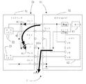
図2を用いて、実施例1に係る信号検出装置1の電源ラインPL2において地絡が生じた際の動作を説明する。EF1点において地絡が生じることで、EF1点の電位が降下し、電源ラインPL2の電流はEF1点を介して大地に電流が流れ込み、電源ラインPL2を介してホールIC1及びホールIC2に電力を供給することができなくなる。一方、電流ラインPL1を流れる電流は、電流ラインPL2上に整流素子41があるため、電源ラインPL1から電源ライン接続部42を介してEF1点へは短絡電流は流れ込まない。したがって、電源ラインPL1を介して、ホールIC1及びホールIC2に電力供給を行うことができる。
(During ground fault)
The operation when a ground fault occurs in the power supply line PL2 of the
なお、第1筐体31と第2筐体32との間に位置する配線は、筐体に覆われていないため、筐体内と比べて相対的に地絡故障等の影響を受けやすいが、整流素子41はホールIC1及びホールIC2と電源ライン接続部42が収容される第1筐体31に収容されているため、第1筐体31と第2筐体32との間において、電源ラインに地絡が生じたとしても、その地絡の影響は他の電源ラインには影響を及ぼすことはない。
In addition, since the wiring located between the 1st housing | casing 31 and the 2nd housing | casing 32 is not covered by the housing | casing, it is easy to receive the influence of a ground fault etc. relatively compared with the inside of a housing | casing, Since the rectifying
(実施例2)
(全体構成)
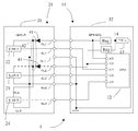
図3に実施例2に係る信号検出装置1のシステム構成図を示す。信号検出装置1は、主にトルクセンサ21と、EPS−ECU11とからなる。トルクセンサ21はステアリングの操舵トルクを検出し、EPS−ECU11は、操舵トルクに基づいて、ステアリングの操舵力をアシストするべくモータを制御する。
(Example 2)
(overall structure)
FIG. 3 shows a system configuration diagram of the
トルクセンサ21とEPS−ECU11とは、電源ラインPL1〜PL3、信号ラインSL1〜SL3及びグランドラインGL1〜GL2によって接続されている。
(トルクセンサ)
トルクセンサ21は、車両のステアリングに作用する操舵トルクを検出し、その検出した操舵トルクに対応するトルク信号を第1信号ラインSL1、第2信号ラインSL2及び第3信号ラインSL3を介してEPS−ECU11側に送信する。トルクセンサ21は、第1筐体31内部に第1信号検出器22であるホールIC1、第2信号検出器23であるホールIC2及び第3信号検出器24であるホールIC3とを有する。
(Torque sensor)
The
(EPS−ECU)
EPS−ECU11は、第2筐体32内部に電源である電源回路13と、レギュレータ14と、信号検出回路であるCPU12とを有する。電源回路13は、車両のボディに接地(ボディアース)されるものであり、電源ラインを介して、トルクセンサ21に電力を供給する。レギュレータ14は、電源回路13から出力する電圧・電流を一定に保つために用いられる。CPU12は、トルクセンサ21側から送信されたトルク信号を受け取り、モータの制御に必要な演算を行う。
(EPS-ECU)
The EPS-
(電源ライン)
第1電源ラインPL1は、電源回路13とホールIC1とを接続し、第2電源ラインPL2は、電源回路13とホールIC2を接続し、第3電源ラインPL3は、第1電源ラインPL1とホールIC3又は第2電源ラインPL2とホールIC3を接続する。電源ライン接続部42は、第1電源ラインPL1と第2電源ラインPL2とを接続する。電源ライン接続部42を介することで、第1電源ラインPL1と第2電源ラインPL2のうちいずれか一方の電源ラインが断線した場合でもホールIC1及びホールIC2が他方の電源ラインから電力供給を受けることができる。さらに、第3電源ラインPL3は、整流素子41と第1信号検出器の間又は整流素子41と第2信号検出器との間において、第1電源ラインPL1又は第2電源ラインPL2と接続される。
(Power line)
The first power supply line PL1 connects the
第3負荷は第1電源ラインPL1及び第2電源ラインPL2を介して電力の供給を受けることができるため、第1電源ラインPL1及び第2電源ラインPL2を利用している分、第3電源ラインPL3の長さを必要最小限にでき、かつ、並列接続する負荷の数だけ整流素子41を設けずに済む。
Since the third load can receive power supply via the first power line PL1 and the second power line PL2, the third power line is used by the amount of the first power line PL1 and the second power line PL2. The length of PL3 can be minimized, and it is not necessary to provide the rectifying
(整流素子)
整流素子41は、第1電源ラインPL1と第2電源ラインPL2それぞれに設けられ、電源ライン接続部42と電源回路13との間に電源回路13から信号検出器に流れる電流のみ通電して逆方向に流れる電流を遮断する。
(Rectifier element)
The rectifying
つまり、電源ライン接続部42が、第1電源ラインPL1又は第2電源ラインPL2の一方の電源ラインから第1電源ラインPL1又は第2電源ラインPL2の他方の電源ラインに流れる短絡電流を遮断するため、第1電源ラインPL1又は第2電源ラインPL2の一方の電源ラインが地絡したとしても、他方の電源ラインを介して電源回路13からホールIC1、ホールIC2及びホールIC3に電力を供給し続けることができる。この結果、第1電源ラインPL1又は第2電源ラインPL2のいずれか一方が地絡しても、他方の電源ラインを用いてホールIC1、ホールIC2及びホールIC3に電力を供給でき、ホールIC1、ホールIC2及びホールIC3は信号検出回路に信号を伝達することができる。
That is, the power supply
(レギュレータ)
レギュレータ14は、第1電源ラインPL1と第2電源ラインPL2それぞれにおいて、整流素子41と電源回路13との間に設けられ、入力電力を所定の出力電力に変換する。レギュレータ14を第1電源ラインPL1及び第2電源ラインPL2それぞれに設けているため、第1電源ラインPL1又は第2電源ラインPL2の一方の電源ラインが地絡して短絡電流が流れて、地絡した電源ラインのレギュレータ14が破壊されたとしても、他方の電源ラインはそのままレギュレータ14を用いることができる。
(regulator)
The
(ホールIC)
ホールIC1は、所定の対象を検出して第1信号を出力する第1信号検出器22であり、ホールIC2は、所定の対象を検出して第2信号を出力する第2信号検出器23であり、ホールIC3は、所定の対象を検出して第3信号を出力する第3信号検出器24である。ここで、所定の対象とはモータのことであり、第1信号と第2信号は、モータのトルク信号に該当する。
(Hall IC)
The
さらに、ホールIC1、ホールIC2及びホールIC3は、電源回路13と並列に接続される。
Further, the
(信号ライン)
第1信号ラインSL1は、信号検出回路とホールIC1を接続して第1信号を伝達し、第2信号ラインSL2は、信号検出回路とホールIC2を接続して第2信号を伝達し、第3信号ラインSL3は信号検出回路とホールIC3を接続して第3信号を伝達する。
(Signal line)
The first signal line SL1 connects the signal detection circuit and the
(信号検出回路)
信号検出回路は、第1信号ラインSL1、第2信号ラインSL2及び第3信号ラインSL3を介して第1信号と第2信号を検出する。
(Signal detection circuit)
The signal detection circuit detects the first signal and the second signal through the first signal line SL1, the second signal line SL2, and the third signal line SL3.
信号検出回路は、実施例1の場合と同様に、第1信号、第2信号、第3信号に基づいて、検出された信号に異常があるか否かを判定する。第1信号、第2信号、第3信号のうち、2つの信号を対比し、両信号が正常か異常か判定する。実施例1の場合、第1信号と第2信号のどちらかに異常があると、どちらの信号が正常かを判定することは困難となる。 As in the case of the first embodiment, the signal detection circuit determines whether the detected signal is abnormal based on the first signal, the second signal, and the third signal. Of the first signal, the second signal, and the third signal, two signals are compared to determine whether both signals are normal or abnormal. In the case of the first embodiment, if either the first signal or the second signal is abnormal, it is difficult to determine which signal is normal.
一方で、実施例2の場合では、第1信号、第2信号及び第3信号のうち、異常な信号が一つだけの場合には、他の二つの正常な信号は互いに比較することで検出できるため、異常を検出し、かつ、正常に操舵の補助を続行することができる。この結果、信号検出装置1の稼働率をあげることができる。
On the other hand, in the case of the second embodiment, when there is only one abnormal signal among the first signal, the second signal, and the third signal, the other two normal signals are detected by comparing with each other. Therefore, the abnormality can be detected and the steering assist can be continued normally. As a result, the operating rate of the
また、第1信号、第2信号及び第3信号のうち、異常な信号が二つある場合には、どれが正常な信号か判断できないため、電動パワーステアリング装置のモータによる操舵の補助を停止する。 In addition, when there are two abnormal signals among the first signal, the second signal, and the third signal, it is impossible to determine which one is a normal signal, so the assist of steering by the motor of the electric power steering apparatus is stopped. .
(グランドライン)
第1グランドラインGL1は、ホールIC1、ホールIC2及びホールIC3をそれぞれ並列に接続し、第2グランドラインGL2は、ホールIC1、ホールIC2及びホールIC3をそれぞれ並列に接続する。
(Grand Line)
The first ground line GL1 connects the Hall IC1, Hall IC2, and Hall IC3 in parallel, and the second ground line GL2 connects the Hall IC1, Hall IC2, and Hall IC3 in parallel.
このように接続することによって、第1グランドラインGL1又は第2グランドラインGL2の一方のグランドラインが断線しても、他方のグランドラインを介することで、ホールIC1、ホールIC2及びホールIC3を接地することができる。 By connecting in this way, even if one ground line of the first ground line GL1 or the second ground line GL2 is disconnected, the Hall IC1, Hall IC2, and Hall IC3 are grounded via the other ground line. be able to.
2本のグランドラインのうち、一方のグランドラインが断線しても、他方のグランドラインを用いて接地できるため、信号検出装置1の信頼性を確保できる。
Even if one of the two ground lines is disconnected, the ground can be grounded using the other ground line, so that the reliability of the
なお、ホールIC1〜ホールIC3をトルクセンサ21側ではなく、EPS−ECU11側で接地するのは、ホールICがEPS−ECU11内の電源回路13から電力を供給受けているため、ホールIC1〜ホールIC3の接地電位を電源回路13の接地電位、つまり、EPS−ECU11の接地電位に揃える必要があることによる。
The reason why the
各信号検出器がそれぞれ独立にグランドラインを設けると、信号検出器の数だけグランドラインが必要となるが、本実施例では、ホールIC1、ホールIC2及びホールIC3は、それぞれ第1グランドラインGL1と第2グランドラインGL2を共用しているため、接地するグランドラインの配線は2本で済む。さらに、2本のグランドラインのうち、一方のグランドラインが断線しても、他方のグランドラインを用いて接地できるため、信号検出装置1の信頼性も確保できる。
If each signal detector is provided with a ground line independently, as many ground lines as the number of signal detectors are required. In this embodiment, Hall IC1, Hall IC2, and Hall IC3 are respectively connected to the first ground line GL1. Since the second ground line GL2 is shared, only two ground lines are required for grounding. Furthermore, even if one of the two ground lines is disconnected, the other ground line can be used for grounding, so that the reliability of the
(筐体)
ホールIC1、ホールIC2及びホールIC3と電源ライン接続部42と整流素子41とは第1筐体31に収容され、電源回路13と信号検出回路とは第2筐体32に収容される。
(地絡時)
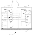
図4を用いて、実施例2に係る信号検出装置1の電源ラインPL2において地絡が生じた際の動作を説明する。EF2点において地絡が生じることで、EF2点の電位が降下し、電源ラインPL2の電流はEF2点を介して大地に電流が流れ込み、電源ラインPL2を介してホールIC1、ホールIC2及びホールIC3に電力を供給することができなくなる。一方、電流ラインPL1を流れる電流は、電流ラインPL2上に整流素子41があるため、電源ラインPL1から電源ライン接続部42を介してEF2点へは短絡電流は流れ込まない。したがって、電源ラインPL1を介して、ホールIC1、ホールIC2及びホールIC3に電力供給を行うことができる。
(Casing)
The
(During ground fault)
An operation when a ground fault occurs in the power supply line PL2 of the
(断線時)
図4を用いて、実施例2に係る信号検出装置1の信号ラインSL3において断線が生じた場合の信号検出回路の処理について説明する。図4は、信号ラインSL3に断線が生じた場合を示している。この場合、ホールIC3が信号ラインSL3を介して送信した第3信号はCPU12に届かず、CPU12において受信される第3信号は、第1信号及び第2信号と異なるトルクを示す信号となる。CPU12は、第1信号と第2信号、第2信号と第3信号、第3信号と第1信号というそれぞれ3つの組み合わせについて、各信号の異同を判定する。この場合、CPU12は、第1信号と第2信号の組み合わせでは互いの信号は同一、第2信号と第3信号、第3信号と第1信号の組み合わせでは互いの信号は異なるという結果を得る。これらの結果から、CPU12は、第1信号と第2信号は互いに同一のトルクを示す信号であるという判定結果から第1信号と第2信号は正常な信号と判定し、さらに、第2信号と第3信号、第3信号と第1信号は互いに異なるトルクを示す信号という判定結果から第3信号は異常信号と判定する。
(When disconnected)
The processing of the signal detection circuit when a disconnection occurs in the signal line SL3 of the
この場合、信号検出回路は、第1信号と第2信号に基づき、モータの制御に必要な演算を行う。実施例1の場合では、第1信号と第2信号が異なるトルクを示した場合、どちらが正しい信号か判定することが困難であるが、実施例2の場合では、第1信号、第2信号及び第3信号を用いるため、正常な信号が2つあれば、2つの信号が同じトルクを示すため、正常な信号に基づいて、操舵補助を続行することが可能となる。 In this case, the signal detection circuit performs a calculation necessary for controlling the motor based on the first signal and the second signal. In the case of the first embodiment, when the first signal and the second signal indicate different torques, it is difficult to determine which is the correct signal. However, in the case of the second embodiment, the first signal, the second signal, and Since the third signal is used, if there are two normal signals, the two signals indicate the same torque. Therefore, the steering assist can be continued based on the normal signal.
なお、第1信号、第2信号、第3信号のうち、2つ以上の異常信号が検出された場合には、正常な信号を判定することが困難であるため、操舵の補助を停止する。 In addition, when two or more abnormal signals are detected among the first signal, the second signal, and the third signal, it is difficult to determine a normal signal, and thus steering assistance is stopped.
(実施例3)
図5に実施例3に係る信号検出装置1のシステム構成図を示す。ここでは、実施例2における信号検出装置1との相違点についてのみ説明し、共通点の説明については省略する。
(Example 3)
FIG. 5 is a system configuration diagram of the
実施例3では、第2グランドラインGL2に代えて、ホールIC1(第1信号検出器22)、ホールIC2(第2信号検出器23)及びホールIC3(第3信号検出器24)は、第2グランドラインGL2に代えて、車両のボディ51に接地される。電源回路13は、車両のボディ51にも接地されているため、ホールIC1〜ホールIC3を車両のボディ51に接地することで、ホールIC1〜ホールCI3と電源回路13との接地電位を揃えることができる。そのため、実施例2に含まれていたグランドラインGL2が不要となる。
In the third embodiment, instead of the second ground line GL2, the Hall IC 1 (first signal detector 22), the Hall IC 2 (second signal detector 23), and the Hall IC 3 (third signal detector 24) are the second Instead of the ground line GL2, the
また、第2グランドラインGL2ではなく、第1グランドラインGL1に代えて、ホールIC1(第1信号検出器22)、ホールIC2(第2信号検出器23)及びホールIC3(第3信号検出器24)を、車両のボディ51に接地しても良い。
Further, instead of the first ground line GL1 instead of the second ground line GL2, the Hall IC 1 (first signal detector 22), the Hall IC 2 (second signal detector 23), and the Hall IC 3 (
なお、電源回路13は、車両のボディ51に接地され、グランドラインGL1とボディアースとの間の電位差は出荷前に、電位差補正を行うことでゼロにされる。
The
1 信号検出装置
11 EPS−ECU
12 CPU(信号検出回路)
13 電源回路(電源)
14 レギュレータ
21 トルクセンサ
22 第1信号検出器(ホールIC1、第1負荷)
23 第2信号検出器(ホールIC2、第2負荷)
24 第3信号検出器(ホールIC3)
31 第1筐体
32 第2筐体
41 整流素子
42 電源ライン接続部
51 ボディ
PL1 第1電源ライン
PL2 第2電源ライン
PL3 第3電源ライン
SL1 第1信号ライン
SL2 第2信号ライン
SL3 第3信号ライン
GL1 第1グランドライン
GL2 第2グランドライン
1
12 CPU (signal detection circuit)
13 Power supply circuit (Power supply)
14
23 Second signal detector (Hall IC2, second load)
24 Third signal detector (Hall IC3)
31 1st housing | casing 32 2nd housing | casing 41
Claims (10)
それぞれ前記整流素子と前記電源との間に
入力電力を所定の出力電力に変換するレギュレータを有する
ことを特徴とする請求項1記載の電力供給回路。 The first power line and the second power line are:
The power supply circuit according to claim 1, further comprising a regulator for converting input power into predetermined output power between the rectifier element and the power source.
前記所定の対象を検出して第2信号を出力する第2信号検出器と、
前記第1信号検出器と前記第2信号検出器とに並列接続される電源と、
前記電源と前記第1信号検出器を接続する第1電源ラインと、
前記電源と前記第2信号検出器を接続する第2電源ラインと、
前記第1信号を伝達する第1信号ラインと、
前記第2信号を伝達する第2信号ラインと、
前記第1信号ライン及び前記第2信号ラインを介して前記第1信号と前記第2信号とを検出する信号検出回路と、
前記第1電源ラインと前記第2電源ラインのうちいずれか一方の電源ラインが断線した場合でも前記第1信号検出器及び前記第2信号検出器が他方の電源ラインから電力供給を受けることができるように前記第1電源ラインと前記第2電源ラインを接続した電源ライン接続部と、
を有し、
前記第1電源ライン及び前記第2電源ラインは、それぞれ前記電源ライン接続部と前記電源との間に前記電源から前記信号検出器に流れる電流のみ通電して逆方向に流れる電流を遮断する整流素子を設けることを特徴とする信号検出装置。 A first signal detector for detecting a predetermined object and outputting a first signal;
A second signal detector that detects the predetermined object and outputs a second signal;
A power supply connected in parallel to the first signal detector and the second signal detector;
A first power line connecting the power source and the first signal detector;
A second power line connecting the power source and the second signal detector;
A first signal line for transmitting the first signal;
A second signal line for transmitting the second signal;
A signal detection circuit for detecting the first signal and the second signal via the first signal line and the second signal line;
Even when one of the first power line and the second power line is disconnected, the first signal detector and the second signal detector can receive power from the other power line. A power line connecting portion connecting the first power line and the second power line,
Have
The first power supply line and the second power supply line are rectifier elements that cut off the current flowing in the reverse direction by energizing only the current flowing from the power supply to the signal detector between the power supply line connecting portion and the power supply, respectively. A signal detection device comprising:
それぞれ前記整流素子と前記電源との間に
入力電力を所定の出力電力に変換するレギュレータを有する
ことを特徴とする請求項3記載の信号検出装置。 The first power line and the second power line are:
The signal detection device according to claim 3, further comprising a regulator that converts input power into predetermined output power between the rectifier element and the power source.
前記所定の対象を検出して第2信号を出力する第2信号検出器と、
前記所定の対象を検出して第3信号を出力する第3信号検出器と、
前記第1信号検出器と前記第2信号検出器と前記第3信号検出器とに並列接続される電源と、
前記電源と前記第1信号検出器を接続する第1電源ラインと、
前記電源と前記第2信号検出器を接続する第2電源ラインと、
前記第1電源ライン及び前記第2電源ラインと前記第3信号検出器を接続する第3電源ラインと、
前記第1信号を伝達する第1信号ラインと、
前記第2信号を伝達する第2信号ラインと、
前記第3信号を伝達する第3信号ラインと、
前記第1信号ライン、前記第2信号ライン及び前記第3信号ラインを介して
前記第1信号、前記第2信号及び前記第3信号を検出する信号検出回路と、
前記第1電源ラインと前記第2電源ラインのうちいずれか一方の電源ラインが断線した場合でも
前記第1信号検出器及び前記第2信号検出器が他方の電源ラインから電力供給を受けることができるように
前記第1電源ラインと前記第2電源ラインを接続した電源ライン接続部と、
を有し、
前記第1電源ライン及び前記第2電源ラインは、それぞれ前記電源ライン接続部と前記電源との間に前記電源から前記信号検出器に流れる電流のみ通電して逆方向に流れる電流を遮断する整流素子を設け、
前記第3電源ラインは、前記整流素子と前記第1負荷の間又は前記整流素子と前記第2負荷との間において、前記第1電源ライン及び前記第2電源ラインと接続されることを特徴とする信号検出装置。 A first signal detector for detecting a predetermined object and outputting a first signal;
A second signal detector that detects the predetermined object and outputs a second signal;
A third signal detector for detecting the predetermined object and outputting a third signal;
A power source connected in parallel to the first signal detector, the second signal detector, and the third signal detector;
A first power line connecting the power source and the first signal detector;
A second power line connecting the power source and the second signal detector;
A third power line connecting the first power line and the second power line and the third signal detector;
A first signal line for transmitting the first signal;
A second signal line for transmitting the second signal;
A third signal line for transmitting the third signal;
A signal detection circuit for detecting the first signal, the second signal, and the third signal via the first signal line, the second signal line, and the third signal line;
Even when one of the first power supply line and the second power supply line is disconnected, the first signal detector and the second signal detector can be supplied with power from the other power supply line. A power line connecting portion connecting the first power line and the second power line,
Have
The first power supply line and the second power supply line are rectifier elements that cut off the current flowing in the reverse direction by energizing only the current flowing from the power supply to the signal detector between the power supply line connecting portion and the power supply, respectively. Provided,
The third power line is connected to the first power line and the second power line between the rectifying element and the first load or between the rectifying element and the second load. A signal detection device.
前記第1信号検出器、前記第2信号検出器及び前記第3信号検出器をそれぞれ並列に接続する第2グランドラインと、
を有し、
前記第1信号検出器、前記第2信号検出器及び前記第3信号検出器は、
前記第1グランドライン又は前記第2グランドラインの一方のグランドラインが断線しても他方のグランドラインにより接地されることを特徴とする請求項6記載の信号検出装置。 A first ground line connecting the first signal detector, the second signal detector, and the third signal detector in parallel;
A second ground line connecting the first signal detector, the second signal detector, and the third signal detector in parallel;
Have
The first signal detector, the second signal detector, and the third signal detector are:
7. The signal detection device according to claim 6, wherein even if one of the first ground line or the second ground line is disconnected, the signal is grounded by the other ground line.
前記第1信号検出器、前記第2信号検出器及び前記第3信号検出器はそれぞれ前記ステアリングに作用する操舵トルクを検出するホールICであることを特徴とする請求項6ないし8のいずれか1項記載の信号検出装置。 The signal detection device according to any one of claims 6 to 8, wherein the signal detection device is used in an electric power steering device for assisting a steering force of a vehicle steering based on a steering torque.
9. The hall effect IC according to claim 6, wherein each of the first signal detector, the second signal detector, and the third signal detector is a Hall IC that detects a steering torque acting on the steering. The signal detection device according to item.
Priority Applications (3)
| Application Number | Priority Date | Filing Date | Title |
|---|---|---|---|
| JP2008261010A JP4666045B2 (en) | 2008-10-07 | 2008-10-07 | Signal detection device |
| DE200910044178 DE102009044178A1 (en) | 2008-10-07 | 2009-10-05 | Power supply circuit and signal detection device |
| US12/574,243 US8053936B2 (en) | 2008-10-07 | 2009-10-06 | Power supply circuit and signal detection apparatus |
Applications Claiming Priority (1)
| Application Number | Priority Date | Filing Date | Title |
|---|---|---|---|
| JP2008261010A JP4666045B2 (en) | 2008-10-07 | 2008-10-07 | Signal detection device |
Publications (2)
| Publication Number | Publication Date |
|---|---|
| JP2010093940A true JP2010093940A (en) | 2010-04-22 |
| JP4666045B2 JP4666045B2 (en) | 2011-04-06 |
Family
ID=42063205
Family Applications (1)
| Application Number | Title | Priority Date | Filing Date |
|---|---|---|---|
| JP2008261010A Expired - Fee Related JP4666045B2 (en) | 2008-10-07 | 2008-10-07 | Signal detection device |
Country Status (3)
| Country | Link |
|---|---|
| US (1) | US8053936B2 (en) |
| JP (1) | JP4666045B2 (en) |
| DE (1) | DE102009044178A1 (en) |
Cited By (6)
| Publication number | Priority date | Publication date | Assignee | Title |
|---|---|---|---|---|
| JP2013257230A (en) * | 2012-06-13 | 2013-12-26 | Jtekt Corp | Rotation angle sensor and abnormality detection device of rotation angle sensor |
| KR20150027911A (en) * | 2013-09-04 | 2015-03-13 | 현대모비스 주식회사 | Sensor power interface for Motor Driven Power Steering for vehicle, and control method thereof |
| JP2016128308A (en) * | 2015-01-09 | 2016-07-14 | トヨタ自動車株式会社 | Power supply |
| JP2017165314A (en) * | 2016-03-17 | 2017-09-21 | 株式会社デンソー | Sensor device and electric steering device using the same |
| JP2018043578A (en) * | 2016-09-13 | 2018-03-22 | 日立オートモティブシステムズ株式会社 | Sensor device |
| WO2021070824A1 (en) * | 2019-10-10 | 2021-04-15 | 株式会社デンソー | Dynamo-electric machine system |
Families Citing this family (3)
| Publication number | Priority date | Publication date | Assignee | Title |
|---|---|---|---|---|
| DE102015114630B4 (en) * | 2015-09-02 | 2024-09-05 | Robert Bosch Gmbh | SENSOR DEVICE, STEERING SYSTEM |
| JP2017081387A (en) * | 2015-10-27 | 2017-05-18 | Kyb株式会社 | Sensor device and electric power steering device |
| DE102019134505A1 (en) * | 2019-12-16 | 2021-06-17 | Knorr-Bremse Systeme für Nutzfahrzeuge GmbH | Measuring system for recording a physical parameter and method for operating a measuring system |
Citations (9)
| Publication number | Priority date | Publication date | Assignee | Title |
|---|---|---|---|---|
| JPS5473931U (en) * | 1977-11-05 | 1979-05-25 | ||
| JPS54105743A (en) * | 1978-01-30 | 1979-08-20 | Nec Corp | Power supply system |
| JPH03249529A (en) * | 1990-02-28 | 1991-11-07 | Atsugi Unisia Corp | Torque sensor |
| JPH05112189A (en) * | 1991-10-21 | 1993-05-07 | Sumitomo Wiring Syst Ltd | Earthing device of electric equipment |
| JPH10108363A (en) * | 1996-09-25 | 1998-04-24 | Sony Corp | Power system for parallel use |
| JP2003137111A (en) * | 2001-11-06 | 2003-05-14 | Koyo Seiko Co Ltd | Electric power steering device |
| JP2004163303A (en) * | 2002-11-14 | 2004-06-10 | Denso Corp | Torque sensor |
| JP2007295658A (en) * | 2006-04-21 | 2007-11-08 | Nsk Ltd | Motor controller and motor-driven power steering controller employing the same |
| JP2008302825A (en) * | 2007-06-08 | 2008-12-18 | Honda Motor Co Ltd | Power source device for vehicle |
Family Cites Families (3)
| Publication number | Priority date | Publication date | Assignee | Title |
|---|---|---|---|---|
| DE2750456B1 (en) | 1977-11-11 | 1979-05-03 | Dornier System Gmbh | Spinning rotor for OE rotor spinning machine |
| DE10362129B8 (en) | 2002-11-14 | 2013-08-08 | Denso Corporation | Highly reliable torque sensor |
| US7265458B2 (en) * | 2005-04-08 | 2007-09-04 | Eaton Power Quality Corporation | Apparatus and methods for coordinated static switch operations for load transfers in uninterruptible power supply systems |
-
2008
- 2008-10-07 JP JP2008261010A patent/JP4666045B2/en not_active Expired - Fee Related
-
2009
- 2009-10-05 DE DE200910044178 patent/DE102009044178A1/en not_active Withdrawn
- 2009-10-06 US US12/574,243 patent/US8053936B2/en not_active Expired - Fee Related
Patent Citations (9)
| Publication number | Priority date | Publication date | Assignee | Title |
|---|---|---|---|---|
| JPS5473931U (en) * | 1977-11-05 | 1979-05-25 | ||
| JPS54105743A (en) * | 1978-01-30 | 1979-08-20 | Nec Corp | Power supply system |
| JPH03249529A (en) * | 1990-02-28 | 1991-11-07 | Atsugi Unisia Corp | Torque sensor |
| JPH05112189A (en) * | 1991-10-21 | 1993-05-07 | Sumitomo Wiring Syst Ltd | Earthing device of electric equipment |
| JPH10108363A (en) * | 1996-09-25 | 1998-04-24 | Sony Corp | Power system for parallel use |
| JP2003137111A (en) * | 2001-11-06 | 2003-05-14 | Koyo Seiko Co Ltd | Electric power steering device |
| JP2004163303A (en) * | 2002-11-14 | 2004-06-10 | Denso Corp | Torque sensor |
| JP2007295658A (en) * | 2006-04-21 | 2007-11-08 | Nsk Ltd | Motor controller and motor-driven power steering controller employing the same |
| JP2008302825A (en) * | 2007-06-08 | 2008-12-18 | Honda Motor Co Ltd | Power source device for vehicle |
Cited By (9)
| Publication number | Priority date | Publication date | Assignee | Title |
|---|---|---|---|---|
| JP2013257230A (en) * | 2012-06-13 | 2013-12-26 | Jtekt Corp | Rotation angle sensor and abnormality detection device of rotation angle sensor |
| KR20150027911A (en) * | 2013-09-04 | 2015-03-13 | 현대모비스 주식회사 | Sensor power interface for Motor Driven Power Steering for vehicle, and control method thereof |
| KR102071405B1 (en) * | 2013-09-04 | 2020-03-03 | 현대모비스 주식회사 | Sensor power interface for Motor Driven Power Steering for vehicle, and control method thereof |
| JP2016128308A (en) * | 2015-01-09 | 2016-07-14 | トヨタ自動車株式会社 | Power supply |
| JP2017165314A (en) * | 2016-03-17 | 2017-09-21 | 株式会社デンソー | Sensor device and electric steering device using the same |
| JP2018043578A (en) * | 2016-09-13 | 2018-03-22 | 日立オートモティブシステムズ株式会社 | Sensor device |
| WO2021070824A1 (en) * | 2019-10-10 | 2021-04-15 | 株式会社デンソー | Dynamo-electric machine system |
| JP2021064996A (en) * | 2019-10-10 | 2021-04-22 | 株式会社デンソー | Rotary electric machine system |
| JP7298433B2 (en) | 2019-10-10 | 2023-06-27 | 株式会社デンソー | Rotating electrical system |
Also Published As
| Publication number | Publication date |
|---|---|
| JP4666045B2 (en) | 2011-04-06 |
| DE102009044178A1 (en) | 2010-05-06 |
| US20100084216A1 (en) | 2010-04-08 |
| US8053936B2 (en) | 2011-11-08 |
Similar Documents
| Publication | Publication Date | Title |
|---|---|---|
| JP4666045B2 (en) | Signal detection device | |
| JP6999480B2 (en) | Electronic control device and its diagnostic method | |
| JP5898104B2 (en) | Power supply voltage monitoring circuit, vehicle sensor circuit, and power steering device | |
| JP5924510B2 (en) | Redundant arithmetic processing system | |
| JP2013079027A (en) | Electric power steering device | |
| US20190233002A1 (en) | Motor control system and electric power steering system | |
| CN107406096B (en) | Power steering device and control device for vehicle-mounted equipment | |
| US9221492B2 (en) | Method for operating an electrical power steering mechanism | |
| WO2013137059A1 (en) | Abnormality diagnosis device and abnormality diagnosis method for torque sensor | |
| US20180304916A1 (en) | Sensor device and electric power steering device | |
| US10060983B2 (en) | Method and apparatus for determining a physical quantity of a multiphase synchronous machine | |
| JP2018043578A (en) | Sensor device | |
| JP5001920B2 (en) | Vehicle steering system | |
| CN108702099B (en) | Electronic control device and electric power steering device equipped with same | |
| KR20080090833A (en) | Electronic controller provides short circuit detection of vehicle speed and engine speed signals | |
| KR102281672B1 (en) | Electronic control apparatus and method for eps | |
| KR20150065986A (en) | Electronic control unit for detecting breakdown of motor position sensor | |
| WO2021117636A1 (en) | Drive control device for electric motor | |
| JP2008017406A (en) | Relay drive controller | |
| JP4779380B2 (en) | Brushless motor and electric power steering apparatus using the same | |
| KR20140110424A (en) | Apparatus and method for torque sensor fault detection | |
| JP2005193834A (en) | Control device of electric power steering device | |
| KR102494675B1 (en) | Fail Safe Apparatus For Electric Power Steering System And Method Thereof | |
| JP2009120076A (en) | Electronic control device and vehicle control system | |
| KR101195725B1 (en) | Electronic Control Unit for Motor Control |
Legal Events
| Date | Code | Title | Description |
|---|---|---|---|
| A621 | Written request for application examination |
Free format text: JAPANESE INTERMEDIATE CODE: A621 Effective date: 20100215 |
|
| A977 | Report on retrieval |
Free format text: JAPANESE INTERMEDIATE CODE: A971007 Effective date: 20100716 |
|
| A131 | Notification of reasons for refusal |
Free format text: JAPANESE INTERMEDIATE CODE: A131 Effective date: 20100727 |
|
| RD01 | Notification of change of attorney |
Free format text: JAPANESE INTERMEDIATE CODE: A7421 Effective date: 20100802 |
|
| A521 | Written amendment |
Free format text: JAPANESE INTERMEDIATE CODE: A523 Effective date: 20100921 |
|
| TRDD | Decision of grant or rejection written | ||
| A01 | Written decision to grant a patent or to grant a registration (utility model) |
Free format text: JAPANESE INTERMEDIATE CODE: A01 Effective date: 20101214 |
|
| A01 | Written decision to grant a patent or to grant a registration (utility model) |
Free format text: JAPANESE INTERMEDIATE CODE: A01 |
|
| A61 | First payment of annual fees (during grant procedure) |
Free format text: JAPANESE INTERMEDIATE CODE: A61 Effective date: 20101227 |
|
| FPAY | Renewal fee payment (event date is renewal date of database) |
Free format text: PAYMENT UNTIL: 20140121 Year of fee payment: 3 |
|
| R151 | Written notification of patent or utility model registration |
Ref document number: 4666045 Country of ref document: JP Free format text: JAPANESE INTERMEDIATE CODE: R151 |
|
| FPAY | Renewal fee payment (event date is renewal date of database) |
Free format text: PAYMENT UNTIL: 20140121 Year of fee payment: 3 |
|
| R250 | Receipt of annual fees |
Free format text: JAPANESE INTERMEDIATE CODE: R250 |
|
| R250 | Receipt of annual fees |
Free format text: JAPANESE INTERMEDIATE CODE: R250 |
|
| R250 | Receipt of annual fees |
Free format text: JAPANESE INTERMEDIATE CODE: R250 |
|
| R250 | Receipt of annual fees |
Free format text: JAPANESE INTERMEDIATE CODE: R250 |
|
| R250 | Receipt of annual fees |
Free format text: JAPANESE INTERMEDIATE CODE: R250 |
|
| R250 | Receipt of annual fees |
Free format text: JAPANESE INTERMEDIATE CODE: R250 |
|
| LAPS | Cancellation because of no payment of annual fees |