JP2007295658A - Motor controller and motor-driven power steering controller employing the same - Google Patents
Motor controller and motor-driven power steering controller employing the same Download PDFInfo
- Publication number
- JP2007295658A JP2007295658A JP2006117786A JP2006117786A JP2007295658A JP 2007295658 A JP2007295658 A JP 2007295658A JP 2006117786 A JP2006117786 A JP 2006117786A JP 2006117786 A JP2006117786 A JP 2006117786A JP 2007295658 A JP2007295658 A JP 2007295658A
- Authority
- JP
- Japan
- Prior art keywords
- motor
- brushless motor
- abnormality
- circuit
- switching means
- Prior art date
- Legal status (The legal status is an assumption and is not a legal conclusion. Google has not performed a legal analysis and makes no representation as to the accuracy of the status listed.)
- Pending
Links
Images


Classifications
-
- Y—GENERAL TAGGING OF NEW TECHNOLOGICAL DEVELOPMENTS; GENERAL TAGGING OF CROSS-SECTIONAL TECHNOLOGIES SPANNING OVER SEVERAL SECTIONS OF THE IPC; TECHNICAL SUBJECTS COVERED BY FORMER USPC CROSS-REFERENCE ART COLLECTIONS [XRACs] AND DIGESTS
- Y02—TECHNOLOGIES OR APPLICATIONS FOR MITIGATION OR ADAPTATION AGAINST CLIMATE CHANGE
- Y02B—CLIMATE CHANGE MITIGATION TECHNOLOGIES RELATED TO BUILDINGS, e.g. HOUSING, HOUSE APPLIANCES OR RELATED END-USER APPLICATIONS
- Y02B70/00—Technologies for an efficient end-user side electric power management and consumption
- Y02B70/10—Technologies improving the efficiency by using switched-mode power supplies [SMPS], i.e. efficient power electronics conversion e.g. power factor correction or reduction of losses in power supplies or efficient standby modes
Abstract
Description
本発明は、ブラシレスモータを駆動制御するモータ制御装置及びこれを用いた電動パワーステアリング制御装置に関し、特に、その動作の信頼性を向上させるようにしたものである。 The present invention relates to a motor control device for driving and controlling a brushless motor and an electric power steering control device using the motor control device, and in particular, to improve the operation reliability.
従来、この種のモータ制御装置を用いた電動パワーステアリング制御装置においては、電動パワーステアリング装置の動作を常時監視し、万が一電動パワーステアリング装置の故障を検出したときには、モータの駆動を停止すると共に、前記モータを駆動するためのブリッジ回路と電源との間に介挿されたリレーを開放状態に切り換え、ブリッジ回路への給電を停止することによって、前記モータから意図しない操舵補助力が発生されることを回避している(例えば、特許文献1参照)。 Conventionally, in an electric power steering control device using this type of motor control device, the operation of the electric power steering device is constantly monitored, and when a failure of the electric power steering device is detected, the driving of the motor is stopped, An unintended steering assist force is generated from the motor by switching the relay inserted between the bridge circuit for driving the motor and the power supply to an open state and stopping the power supply to the bridge circuit. (For example, refer to Patent Document 1).
また、モータを駆動するためのブリッジ回路を構成するスイッチング素子の異常や、ブリッジ回路とモータとの間での短絡や地絡等によって、前記モータを含む意図しない閉回路が形成され、これによって、モータから意図しない操舵補助力が発生したり、逆に、モータが電磁ブレーキとして動作し運転者の操舵操作を妨げる方向に作用したりすることを回避するために、前記モータとブリッジ回路とを接続するラインに、前記モータ及びブリッジ回路間の接続を遮断するためのリレー回路を設け、短絡、地絡等を検出した場合には、リレー回路を開放状態に切り換えるようにしたもの、また、励磁コイルがスター結線されたモータの中性点に閉回路開放用のスイッチング手段を接続し、モータ駆動回路に閉回路が形成された場合には、このスイッチング手段を開放状態に切り換え中性点を開放することにより、異常な閉回路の形成を回避するようにしたもの等も提案されている(例えば、特許文献2参照)。
しかしながら、上記従来例のように、電源とブリッジ回路との間に設けたリレー回路により、モータへの電力供給を遮断するようにした方法、或いは、ブリッジ回路とモータとの間に設けたリレー回路により、モータへの電力供給を遮断するようにした方法にあっては、例えばリレー回路とモータとの間で短絡や地絡が生じた場合等、意図しない閉回路の形成を回避することができない可能性がある。このようなモータとブリッジ回路との間の接続ラインにおける短絡や地絡によりモータの励磁コイルを含んで形成される閉回路は、上述のように、モータの中性点に設けたリレー回路を開放することにより回避することができる。 However, as in the above-described conventional example, a method in which the power supply to the motor is cut off by a relay circuit provided between the power supply and the bridge circuit, or a relay circuit provided between the bridge circuit and the motor. Thus, in the method in which the power supply to the motor is cut off, for example, when a short circuit or a ground fault occurs between the relay circuit and the motor, the formation of an unintended closed circuit cannot be avoided. there is a possibility. A closed circuit formed by including a motor excitation coil due to a short circuit or ground fault in the connection line between the motor and the bridge circuit, as described above, opens the relay circuit provided at the neutral point of the motor. This can be avoided.
ここで、近年、電動パワーステアリング制御装置の大出力化に伴い、モータの大電流化も進んでいる。このため、上述のようにモータの中性点にリレー回路を設けた場合、リレー回路も大型化することになる。リレー回路は、その大型化に伴ってその作動音も大きくなるため、電動パワーステアリング制御装置の起動時等といったリレー回路動作時に、その作動音が発生するため、この電動パワーステアリング制御装置が搭載された車両の商品性を損ねる可能性がある。また、機械式接点を有するリレー回路においては、リレー回路自体は正常であったとしても、リレー回路の固定接点と可動接点との間に異物が混入することによる導通異常や、固定接点と可動接点とが溶着することにより開放状態とならない溶着異常等が生じる可能性がある。 Here, in recent years, with the increase in the output of the electric power steering control device, the increase in the current of the motor is also progressing. For this reason, when the relay circuit is provided at the neutral point of the motor as described above, the relay circuit is also enlarged. Since the operating noise of the relay circuit increases as the size of the relay circuit increases, the operating noise is generated when the relay circuit is activated, such as when the electric power steering controller is activated. There is a possibility that the merchantability of the vehicle will be damaged. In addition, in a relay circuit having a mechanical contact, even if the relay circuit itself is normal, a continuity abnormality caused by foreign matter mixed between the fixed contact and the movable contact of the relay circuit, or the fixed contact and the movable contact There is a possibility that a welding abnormality that does not become an open state occurs due to the welding.
また、このようにリレー回路を設けることは、モータの低抵抗化に伴い、モータライン上のリレー回路の抵抗や、モータに対して無視できない抵抗値のためその発熱の点でも改善が望まれていた。
そこで、この発明は、上記従来の未解決の課題に着目してなされたものであり、意図しない閉回路の形成を確実に回避し且つ、これを、発熱或いは動作音、ライン抵抗の増加等を伴うことなく実現することの可能なモータ制御装置及びこれを用いた電動パワーステアリング制御装置を提供することを目的としている。
In addition, the provision of a relay circuit in this way is accompanied by a reduction in the resistance of the motor, and the improvement of the heat generation due to the resistance of the relay circuit on the motor line and the resistance value that cannot be ignored with respect to the motor is desired. It was.
Therefore, the present invention has been made paying attention to the above-mentioned conventional unsolved problems, and reliably avoids the formation of an unintended closed circuit, and reduces the generation of heat, operating noise, line resistance, etc. It is an object of the present invention to provide a motor control device that can be realized without accompanying, and an electric power steering control device using the same.
上記目的を達成するために、本発明の請求項1に係るモータ制御装置は、ブラシレスモータと、当該ブラシレスモータ及び電源間に接続され且つ複数のスイッチング素子から構成されるインバータを備えたモータ駆動回路と、当該モータ駆動回路を制御し前記ブラシレスモータを駆動制御する制御手段と、を備えたモータ制御装置において、前記ブラシレスモータの励磁コイル毎に設けられ且つ前記ブラシレスモータのハウジング内部に配置される、低オン抵抗型の半導体素子からなる閉回路開放用のスイッチング手段と、当該モータ制御装置の異常を検出する異常検出手段と、を備え、前記制御手段は、前記異常検出手段で異常を検出したとき前記スイッチング手段を開放状態に切り換えることを特徴としている。
In order to achieve the above object, a motor control device according to
この請求項1記載の発明では、ブラシレスモータの励磁コイル毎に閉回路開放用のスイッチング手段が設けられ、異常検出手段で、インバータを構成するスイッチング素子の異常や、地絡、ライン間ショート等、モータ制御装置の異常が検出されたときには、スイッチング手段が開放状態に切り換えられ、各励磁コイルに電流が流れることが回避されるから、異常の発生によって、励磁コイルを含んだ閉回路の形成が回避されることになる。このとき、スイッチング手段は、低オン抵抗型の半導体素子から構成されその発熱量の影響を考慮する必要がないからこのスイッチング手段をブラシレスモータのハウジング内に設けたとしても何ら問題はない。また、スイッチング手段を短絡や地絡等の発生する可能性が低いハウジング内に設けているから、ブラシレスモータとモータ駆動回路との間でライン間ショートや地絡等が発生しこれによって閉回路が形成されたとしても、その発生位置に関わらず、励磁コイルに設けたスイッチング手段を開放状態にすることによって閉回路の形成が確実に回避される。 In the first aspect of the present invention, a switching means for opening a closed circuit is provided for each excitation coil of the brushless motor, and the abnormality detecting means detects abnormality of the switching element constituting the inverter, ground fault, short between lines, etc. When an abnormality of the motor control device is detected, the switching means is switched to the open state, and current is prevented from flowing through each exciting coil, so that the formation of a closed circuit including the exciting coil is avoided by the occurrence of the abnormality. Will be. At this time, since the switching means is composed of a low on-resistance type semiconductor element and it is not necessary to consider the influence of the amount of heat generated, there is no problem even if this switching means is provided in the housing of the brushless motor. In addition, since the switching means is provided in the housing that is unlikely to cause a short circuit or a ground fault, a short circuit between lines or a ground fault occurs between the brushless motor and the motor drive circuit, which causes a closed circuit. Even if it is formed, the formation of a closed circuit is surely avoided by opening the switching means provided in the exciting coil regardless of the generation position.
また、請求項2に係るモータ制御装置は、前記ブラシレスモータは、励磁コイルがスター結線されたブラシレスモータであって、前記スイッチング手段を前記ブラシレスモータの中性点と前記励磁コイルとの間に設け、且つ当該スイッチング手段を、前記中性点を形成した回路基板上に配置したことを特徴としている。
この請求項2に係る発明では、スター結線されたブラシレスモータの、各励磁コイルにおいて、ブラレシレスモータの中性点と各励磁コイルとの間に前記スイッチング手段を設け、さらに、このスイッチング手段を、前記中性点を形成した回路基板上に配置したから、スイッチング手段を開放状態に切り換えて中性点を開放することで励磁コイルを含んだ閉回路の形成を回避することが可能となる。また、スイッチング手段を、中性点を形成した回路基板上に配置し、既存の回路基板上に配置したから大幅な変更を伴うことなくスイッチング手段をハウジング内に配置することが可能となる。
In the motor control device according to claim 2, the brushless motor is a brushless motor in which an excitation coil is star-connected, and the switching means is provided between a neutral point of the brushless motor and the excitation coil. The switching means is arranged on the circuit board on which the neutral point is formed.
In the invention according to claim 2, in each excitation coil of the starless brushless motor, the switching means is provided between the neutral point of the braresileless motor and each excitation coil. Since the neutral point is arranged on the circuit board, it is possible to avoid the formation of a closed circuit including the exciting coil by switching the switching means to the open state to open the neutral point. Further, since the switching means is arranged on the circuit board on which the neutral point is formed and arranged on the existing circuit board, the switching means can be arranged in the housing without significant change.
また、請求項3に係るモータ制御装置は、前記スイッチング手段は、前記半導体素子及びこの半導体素子に逆並列に接続されたダイオードで構成され、前記半導体素子は、全ての励磁コイルにおいて、前記半導体素子を流れる電流方向が、前記ブラシレスモータの中性点に対して同一となるように設けられ、前記制御手段は、前記異常検出手段で異常を検出したとき、全ての励磁コイルの前記スイッチング手段を開放状態に切り換えることを特徴としている。 According to a third aspect of the present invention, in the motor control device, the switching unit includes the semiconductor element and a diode connected in antiparallel to the semiconductor element, and the semiconductor element is included in all the exciting coils. The control means opens the switching means of all the excitation coils when an abnormality is detected by the abnormality detection means. It is characterized by switching to a state.
この請求項3に係る発明では、半導体素子とこの半導体素子に逆並列に接続されたダイオードとでスイッチング手段を構成し、且つ、スイッチング手段の半導体素子を流れる中性点に対する電流方向が、各励磁コイルに設けた全てのスイッチング手段間で同一となるようにスイッチング手段を設けている。このため、各励磁コイルに設けられたスイッチング手段を全て開放状態とすることによって、半導体素子及びダイオードの何れかによって電流の流れが阻止されるから、各励磁コイルを流れる電流の向きに関わらず、全ての励磁コイルにおける電流の流れが遮断されることになる。 In the invention according to claim 3, the semiconductor element and the diode connected in reverse parallel to the semiconductor element constitute a switching means, and the current direction with respect to the neutral point flowing through the semiconductor element of the switching means is determined by each excitation. Switching means is provided so as to be the same among all the switching means provided in the coil. For this reason, by making all the switching means provided in each excitation coil open, the flow of current is blocked by either the semiconductor element or the diode, so regardless of the direction of the current flowing through each excitation coil, The current flow in all the exciting coils is cut off.
また、請求項4に係るモータ制御装置は、前記制御手段は、前記異常検出手段で検出した異常の内容に基づいて、各励磁コイルに設けられた前記スイッチング手段のうちの何れかを開放状態に切り換えることにより前記異常の発生に伴う意図しない閉回路の形成を回避し、且つ前記スイッチング手段を開放状態に切り換えた状態で前記ブラシレスモータを制御可能かどうか判定する制御継続判定手段と、当該制御継続判定手段で前記ブラシレスモータを継続制御可能と判定されるとき、前記ブラシレスモータを継続制御可能とし得るスイッチング手段を開放状態に切り換えると共に、当該スイッチング手段を開放状態に切り換えた状態で前記ブラシレスモータを駆動するための継続制御を行う継続制御手段と、を備えることを特徴としている。 According to a fourth aspect of the present invention, in the motor control device according to the fourth aspect, the control means opens any one of the switching means provided in each excitation coil based on the content of the abnormality detected by the abnormality detection means. Control continuation determining means for determining whether or not the brushless motor can be controlled in a state where the switching means is switched to an open state while avoiding the formation of an unintended closed circuit due to the occurrence of the abnormality by switching, and the control continuation When it is determined by the determination means that the brushless motor can be continuously controlled, the switching means that can continuously control the brushless motor is switched to the open state, and the brushless motor is driven with the switching means switched to the open state. And continuation control means for performing continuation control to perform
この請求項4に係る発明では、異常検出手段で異常が検出されたとき、何れかのスイッチング手段を開放状態に切り換えることにより、前記異常の発生による意図しない閉回路の形成を回避することができ、且つスイッチング手段を開放状態に切り換えた状態でブラシレスモータを引き続き駆動制御することが可能かどうかの判定が行われる。そして、スイッチング手段を開放状態に切り換えることによって、閉回路の形成を回避し且つブラシレスモータの継続制御が可能と判定されるとき、該当するスイッチング手段を開放状態に切り換え、このスイッチング手段を開放状態にした状態で、ブラシレスモータを駆動するための継続制御が行われる。したがって、ブラシレスモータを滑らかに制御することは困難ではあるものの、意図しない閉回路が形成されることによるブラシレスモータの誤動作を回避しつつ、ブラシレスモータを引き続き駆動することが可能となる。 In the invention according to claim 4, when an abnormality is detected by the abnormality detection means, it is possible to avoid the formation of an unintended closed circuit due to the occurrence of the abnormality by switching any of the switching means to the open state. In addition, it is determined whether or not the brushless motor can be continuously controlled with the switching means switched to the open state. When it is determined that the closed circuit can be avoided and the brushless motor can be continuously controlled by switching the switching unit to the open state, the corresponding switching unit is switched to the open state, and the switching unit is opened. In this state, continuous control for driving the brushless motor is performed. Therefore, although it is difficult to control the brushless motor smoothly, the brushless motor can be continuously driven while avoiding malfunction of the brushless motor due to the formation of an unintended closed circuit.
また、請求項5に係るモータ制御装置は、前記スイッチング手段は、前記半導体素子及びこの半導体素子に逆並列に接続されたダイオードからなる第1のスイッチ回路及びこれと同一構成を有する第2のスイッチ回路で構成され、且つ前記第1のスイッチ回路及び第2のスイッチ回路はその半導体素子どうしの電流の流れる方向が逆向きとなるように直列に接続され、前記制御手段は、前記異常検出手段で検出した異常の内容に基づいて、各励磁コイルに設けられた前記スイッチング手段のうちの何れかを開放状態に切り換えることにより前記異常の発生に伴う意図しない閉回路の形成を回避し、且つ前記スイッチング手段を開放状態に切り換えた状態で前記ブラシレスモータを制御可能かどうか判定する制御継続判定手段と、当該制御継続判定手段で前記ブラシレスモータを継続制御可能と判定されるとき、前記ブラシレスモータを継続制御可能とし得るスイッチング手段を開放状態に切り換えると共に、当該スイッチング手段を開放状態に切り換えた状態で前記ブラシレスモータを駆動するための継続制御を行う継続制御手段と、を備えることを特徴としている。 According to a fifth aspect of the present invention, in the motor control apparatus according to the fifth aspect, the switching means includes a first switch circuit including the semiconductor element and a diode connected in reverse parallel to the semiconductor element, and a second switch having the same configuration And the first switch circuit and the second switch circuit are connected in series so that the direction of current flow between the semiconductor elements is reversed, and the control means is the abnormality detection means. Based on the content of the detected abnormality, any one of the switching means provided in each exciting coil is switched to an open state to avoid the formation of an unintended closed circuit due to the occurrence of the abnormality, and the switching Control continuation determining means for determining whether or not the brushless motor can be controlled with the means switched to the open state, and the control continuation When the control means determines that the brushless motor can be continuously controlled, the switching means that can continuously control the brushless motor is switched to the open state, and the brushless motor is driven with the switching means switched to the open state. And a continuation control means for performing continuation control.
この請求項5に係る発明では、半導体素子とこの半導体素子と逆並列に接続されたダイオードからなる第1のスイッチ回路と、同様に半導体素子及びダイオードとからなる第2のスイッチ回路とでスイッチング手段を構成し、これらの半導体素子どうしを、その電流の流れる向きが逆となるように直列に接続する。 In the invention according to claim 5, switching means includes a semiconductor element and a first switch circuit comprising a diode connected in antiparallel with the semiconductor element, and a second switch circuit comprising a semiconductor element and a diode. These semiconductor elements are connected in series so that the direction of current flow is reversed.
異常検出手段で異常が検出されたとき、何れかのスイッチング手段を開放状態に切り換えることにより、前記異常の発生による意図しない閉回路の形成を回避することができ、且つスイッチング手段を開放状態に切り換えた状態でブラシレスモータを引き続き駆動制御することが可能かどうかが判定され、スイッチング手段を開放状態に切り換えることによって、閉回路の形成を回避し且つブラシレスモータの継続制御が可能と判定されるとき、該当するスイッチング手段を開放状態に切り換え、このスイッチング手段を開放状態にした状態で、ブラシレスモータを駆動するための継続制御が行われる。したがって、ブラシレスモータを滑らかに制御することは困難ではあるものの、意図しない閉回路が形成されることによるブラシレスモータの誤動作を回避しつつ、ブラシレスモータを引き続き駆動することが可能となる。また、このとき、各励磁コイルに、逆向きに接続された2つの半導体素子を備えたスイッチング手段が設けられているから、2つの半導体素子を共に開放状態とすることによって、この励磁コイルを流れる双方向の電流を確実に遮断することができ、より確実に不要な閉回路の形成を回避することができる。 When an abnormality is detected by the abnormality detection means, by switching any of the switching means to the open state, it is possible to avoid the formation of an unintended closed circuit due to the occurrence of the abnormality, and to switch the switching means to the open state. When it is determined whether it is possible to continue driving control of the brushless motor in a state where it is determined, and by switching the switching means to the open state, it is determined that avoiding the formation of a closed circuit and continuing control of the brushless motor is possible, The corresponding switching means is switched to the open state, and the continuous control for driving the brushless motor is performed in a state where the switching means is in the open state. Therefore, although it is difficult to control the brushless motor smoothly, the brushless motor can be continuously driven while avoiding malfunction of the brushless motor due to the formation of an unintended closed circuit. At this time, since each exciting coil is provided with switching means including two semiconductor elements connected in opposite directions, the two semiconductor elements are opened to flow through the exciting coil. Bidirectional current can be reliably interrupted, and formation of an unnecessary closed circuit can be avoided more reliably.
また、請求項6に係るモータ制御装置は、前記低オン抵抗型の半導体素子は、炭化珪素を素材とする素子であることを特徴としている。
この請求項6に係る発明では、炭化珪素を素材とする半導体素子を用いることによって、低オン抵抗型の半導体素子を容易に実現することが可能となる。
さらに、本発明の請求項7に係る電動パワーステアリング制御装置は、上記請求項1から請求項6の何れか1項に記載のモータ制御装置を、操舵系に操舵補助力を付与するためのモータ制御装置として用いたことを特徴としている。
The motor control device according to a sixth aspect is characterized in that the low on-resistance semiconductor element is an element made of silicon carbide.
In the invention according to claim 6, by using a semiconductor element made of silicon carbide, a low on-resistance type semiconductor element can be easily realized.
Furthermore, an electric power steering control device according to a seventh aspect of the present invention is the motor control device according to any one of the first to sixth aspects, wherein the motor for applying a steering assist force to the steering system. It is used as a control device.
この請求項7に係る発明では、上記請求項1から請求項6の何れか1項に記載のモータ制御装置を、操舵系に操舵補助力を付与する電動パワーステアリング制御装置に適用したから、短絡や地絡等による閉回路の形成をより確実に回避し且つ、この閉回路の形成を回避するためのスイッチング手段を設けることによる作動音や、抵抗、発熱量等による影響をより低減することが可能となり、システムの信頼性を向上させることが可能となる。
In the invention according to claim 7, since the motor control device according to any one of
本発明の請求項1に係るモータ制御装置によれば、ブラシレスモータの励磁コイル毎に、閉回路開放用のスイッチング手段を設け、モータ制御装置の異常を検出したときには、このスイッチング手段を開放状態にして各励磁コイルに電流が流れることを回避するから、閉回路の形成を容易に回避することができる。また、スイッチング手段は、低オン抵抗型の半導体素子で構成しているからこのスイッチング手段を設けることによる抵抗の増加や発熱量、さらに作動音等の発生を伴うことなく実現することができ、発熱量を考慮する必要がないからこのスイッチング手段をブラシレスモータのハウジング内に設けても何ら問題はなく、このスイッチング手段を設けることによる配線の細線化や簡素化を図ることができる。 According to the motor control device of the first aspect of the present invention, the switching means for opening the closed circuit is provided for each excitation coil of the brushless motor, and when the abnormality of the motor control device is detected, the switching means is opened. Therefore, it is possible to easily avoid the formation of a closed circuit because current is prevented from flowing through each exciting coil. In addition, since the switching means is composed of a low on-resistance type semiconductor element, it can be realized without increasing the resistance, the amount of heat generated, and the generation of operating noise, etc. by providing this switching means. Since it is not necessary to consider the amount, there is no problem even if this switching means is provided in the housing of the brushless motor, and the thinning and simplification of the wiring can be achieved by providing this switching means.
また、請求項2に係るモータ制御装置によれば、励磁コイルがスター結線されたブラシレスモータにおいて、スイッチング手段を、ブラシレスモータの中性点と各励磁コイルとの間に設け、さらに、このスイッチング手段を、中性点を形成した回路基板上に配置したから、スイッチング手段を開放状態に切り換えて中性点を開放することで励磁コイルを含んだ閉回路の形成を確実に回避することができると共に、スイッチング手段を既存の回路基板上に配置したから、大幅な変更を伴うことなくスイッチング手段をハウジング内に配置することができる。 According to the motor control device of the second aspect, in the brushless motor in which the excitation coil is star-connected, the switching means is provided between the neutral point of the brushless motor and each excitation coil, and the switching means Is placed on the circuit board on which the neutral point is formed, and by switching the switching means to the open state and opening the neutral point, formation of a closed circuit including the exciting coil can be reliably avoided. Since the switching means is arranged on the existing circuit board, the switching means can be arranged in the housing without significant change.
また、請求項3に係るモータ制御装置によれば、半導体素子とこれに逆並列に接続されたダイオードとでスイッチング手段を構成し、且つ、各励磁コイルに設けられたスイッチング手段は、中性点に対して半導体素子の電流の流れる方向が同一となるように設けられるから、各励磁コイルに設けられたスイッチング手段を全て開放状態とすることによって、各励磁コイルを流れる電流の向きに関わらず、両方向の電流の流れを確実に遮断することができる。 According to the motor control device of the third aspect, the switching means is constituted by the semiconductor element and the diode connected in reverse parallel thereto, and the switching means provided in each exciting coil has a neutral point. In contrast, the semiconductor elements are provided so that the current flows in the same direction, so that all the switching means provided in each exciting coil are opened, regardless of the direction of the current flowing through each exciting coil. The current flow in both directions can be reliably interrupted.
また、請求項4に係るモータ制御装置によれば、異常検出手段で異常が検出された場合であっても、何れかのスイッチング手段を開放状態に切り換えることにより、この異常による閉回路の形成を回避することができ且つブラシレスモータを制御可能な場合には、該当するスイッチング手段を開放状態に切り換え、この状態でブラシレスモータの継続制御を行うから、滑らかに駆動させることはできないものの、ブラシレスモータを引き続き駆動することができる。 Further, according to the motor control device of the fourth aspect, even when an abnormality is detected by the abnormality detection means, a closed circuit is formed by this abnormality by switching any of the switching means to the open state. If it can be avoided and the brushless motor can be controlled, the corresponding switching means is switched to the open state, and the brushless motor is continuously controlled in this state, so the brushless motor cannot be driven smoothly. It can continue to drive.
また、請求項5に係るモータ制御装置によれば、スイッチング手段を、半導体素子とこの半導体素子と逆並列に接続されたダイオードからなる第1のスイッチ回路と同様に構成された第2のスイッチ回路とで構成し、異常が発生した場合でも、何れかのスイッチング手段を開放状態に切り換えることによりこの異常による閉回路の形成を回避することができ且つこの状態でブラシレスモータを制御可能な場合には、該当するスイッチング手段を開放状態に切り換えこの状態でブラシレスモータを駆動制御するから、励磁コイルを流れる双方向の電流を確実に遮断し、ブラシレスモータが意図しない動作をすることを確実に回避しつつ、可能な範囲でブラシレスモータを駆動制御することができる。 Further, according to the motor control device of the fifth aspect, the second switching circuit configured similarly to the first switching circuit including the semiconductor element and the diode connected in antiparallel with the semiconductor element. Even if an abnormality occurs, it is possible to avoid the formation of a closed circuit due to this abnormality by switching any of the switching means to the open state, and when the brushless motor can be controlled in this state Since the brushless motor is driven and controlled in this state by switching the corresponding switching means to the open state, the bidirectional current flowing through the exciting coil is surely cut off, and the brushless motor is reliably prevented from operating unintentionally. The brushless motor can be driven and controlled as much as possible.
また、請求項6に係るモータ制御装置によれば、炭化珪素を素材とする半導体素子を用いることによって、低オン抵抗型の半導体素子を容易に実現することができる。
さらに、本発明の請求項7に係る電動パワーステアリング制御装置によれば、上記請求項1から請求項6の何れか1項に記載のモータ制御装置を、操舵系に操舵補助力を付与するためのモータ制御装置として用いたから、短絡や地絡等による閉回路の形成を確実に回避し且つ、この閉回路の形成を回避するためのスイッチング手段を設けることによる作動音や、抵抗、発熱量等による影響をより低減することができる。
According to the motor control device of the sixth aspect, a low on-resistance type semiconductor element can be easily realized by using a semiconductor element made of silicon carbide.
Furthermore, according to an electric power steering control device of a seventh aspect of the present invention, the motor control device according to any one of the first to sixth aspects is used to apply a steering assist force to the steering system. Because it is used as a motor control device, it is possible to reliably avoid the formation of a closed circuit due to a short circuit, a ground fault, etc., and to provide an operating sound, resistance, heat generation amount, etc. by providing a switching means for avoiding the formation of this closed circuit The influence by can be further reduced.
以下、本発明の実施の形態を説明する。
まず、第1の実施の形態を説明する。
図1は、本発明の一実施形態を示す概略構成図であって、図中、1はステアリングホイールであり、このステアリングホイール1に運転者から作用される操舵力がステアリングシャフト2に伝達される。このステアリングシャフト2は、入力軸2aと出力軸2bとを有し、入力軸2aの一端がステアリングホイール1に連結され、他端は操舵トルク検出手段としての操舵トルクセンサ3を介して出力軸2bの一端に連結されている。
Embodiments of the present invention will be described below.
First, a first embodiment will be described.
FIG. 1 is a schematic configuration diagram showing an embodiment of the present invention, in which 1 is a steering wheel, and a steering force applied to the
そして、出力軸2bに伝達された操舵力は、ユニバーサルジョイント4を介してロアシャフト5に伝達され、さらにユニバーサルジョイント6を介してピニオンシャフト7に伝達される。
このピニオンシャフト7に伝達された操舵力はステアリングギヤ8を介してタイロッド9に伝達され、図示しない転舵輪を転舵させる。ここで、ステアリングギヤ8は、ピニオンシャフト7に連結されたピニオン8aとこのピニオン8aに噛合するラック8bとを有するラックアンドピニオン機構に構成され、ピニオン8aに伝達された回転運動をラック8bで直進運動に変換している。
The steering force transmitted to the
The steering force transmitted to the pinion shaft 7 is transmitted to the tie rod 9 via the
ステアリングシャフト2の出力軸2bには、補助操舵力を出力軸2bに伝達する減速ギヤ10が連結されており、この減速ギヤ10には、操舵系に対して補助操舵力を発生する3相ブラシレスモータ12の出力軸が連結されている。
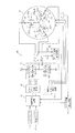
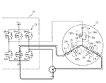
この3相ブラシレスモータ12は、図2に示すように、U相励磁コイルLu、V相励磁コイルLv及びW相励磁コイルLwの一端が互いに接続されてスター結線とされ、各コイルの他端がコントローラ20に接続されて個別にモータ駆動電流Iu、Iv及びIwが供給されると共に、図示しないロータの回転位置を検出するホール素子、レゾルバ等で構成されるロータ位置検出回路13を備えている。
The
As shown in FIG. 2, the three-
また、各励磁コイルLu〜Lwには、それぞれ、3相ブラシレスモータ12の中性点と励磁コイルLu〜Lwとの間に、閉回路開放用のスイッチ回路SWu〜SWwが接続される。この閉回路開放用のスイッチ回路SWu〜SWwは、それぞれ電界効果トランジスタFETu〜FETwと、これと逆並列に接続されたダイオードDu〜Dwとで構成される。前記電界効果トランジスタFETu〜FETwは、低オン抵抗特性を有する低オン抵抗型の電界効果トランジスタで形成され、例えば、パワー素子として広く使用されているSi−IGBTや、Siを用いた場合よりもオン抵抗値の低い、炭化珪素を素材とする電界効果トランジスタで構成される。
In addition, switch circuits SWu to SWw for opening a closed circuit are connected to the respective excitation coils Lu to Lw between the neutral point of the three-
また、これら電界効果トランジスタFETu〜FETwは、これらを流れる電流が、中性点から流れ出る方向となる向きに設けられている。なお、ここでは、中性点から電流が流れ出る方向と、電界効果トランジスタFETu〜FETwを流れる電流の方向とが一致するようにこれら電界効果トランジスタFETu〜FETwを設けた場合について説明したが、電界効果トランジスタFETu〜FETwを流れる電流の向きが、中性点に向かって流れる方向となるように配設してもよく、中性点に対して、電界効果トランジスタFETu〜FETwを流れる電流の向きが同一方向であれば、何れの向きであってもよい。 Further, these field effect transistors FETu to FETw are provided in a direction in which the current flowing therethrough flows out from the neutral point. Here, the case where the field effect transistors FETu to FETw are provided so that the direction in which the current flows from the neutral point coincides with the direction of the current flowing in the field effect transistors FETu to FETw has been described. The direction of the current flowing through the transistors FETu to FETw may be arranged so as to flow toward the neutral point, and the direction of the current flowing through the field effect transistors FETu to FETw is the same as the neutral point. Any direction may be used as long as it is a direction.
これら閉回路開放用のスイッチ回路SWu〜SWwは、図3の3相ブラシレスモータ12の概略構造を示す断面図に示すモータハウジング101内に設けられ、具体的には、各励磁コイルLu〜Lwが接続されて3相ブラシレスモータ12の中性点が形成される回路基板102上に配置される。なお、図3において、103は、回路基板102を保持すると共に、ロータ104の回転位置を検出するためのレゾルバやホール素子等のロータ回転角検出用のセンサ105を保持するためのセンサホルダ、106及び107はロータ104を、モータハウンジング101に対して回転自在に指示するための転がり軸受、108はロータ104と一体に回転するように固定されたロータコア、109はロータ104の回転駆動用のロータマグネット(永久磁石)、110はロータマグネット110から僅かな隙間を介してモータハウジング101の内周面に固定されるモータステータである。
These switch circuits SWu to SWw for opening the closed circuit are provided in a
一方、前記操舵トルクセンサ3は、ステアリングホイール1に付与されて入力軸2aに伝達された操舵トルクを検出するもので、例えば、操舵トルクを入力軸2a及び出力軸2b間に介挿した図示しないトーションバーの捩れ角変位に変換し、この捩れ角変位を例えばポテンショメータで検出するように構成されている。この操舵トルクセンサ3から出力されるトルク検出値Tは、コントローラ20に入力される。
On the other hand, the steering torque sensor 3 detects the steering torque applied to the
このコントローラ20には、操舵トルクセンサ3から出力されるトルク検出値Tや、ロータ位置検出回路13で検出されたロータ回転角θが入力されると共に、さらに、3相ブラシレスモータ12の各励磁コイルLu〜Lwに供給されるモータ駆動電流Iu、Iv及びIwのうち、何れか2つ、例えば、Iu及びIwを検出するモータ電流検出回路22から出力されるモータ駆動電流検出値Iud及びIwdが入力される。
The
コントローラ20は、トルク検出値T及び車速検出値Vとモータ電流検出値Iud及びIwdとロータ回転角θとに基づいて操舵補助電流目標値を演算し、これを電流指令値Iut、Ivt及びIwtとし、この電流指令値Iut、Ivt及びIwtに基づいて決定したデューティ比Du、Dv及びDwのPWM(パルス幅変調)信号を出力する制御演算装置23と、3相ブラシレスモータ12を駆動する電界効果トランジスタ(FET)で構成されるインバータ24と、制御演算装置23から電流指令値Iut、Ivt及びIwtに基づいてインバータ24の電界効果トランジスタのゲート電流を制御するFETゲート駆動回路26と、前記3相ブラシレスモータ12の閉回路開放用の電界効果トランジスタFETu〜FETwのゲート電流を制御する開放用FET駆動回路27と、を備えている。
The
前記インバータ24は、直列に接続された2つの電界効果トランジスタQua及びQubと、同様に直列に接続された2つの電界効果トランジスタQva及びQvbと、直列に接続された電界効果トランジスタQwa及びQwbとを備え、これら直列に接続された電界効果トランジスタが並列に接続されて構成される。なお、各電界効果トランジスタQua〜Qwbにはそれぞれ図示しないダイオードが逆並列に接続されている。
The
このインバータ24の電界効果トランジスタQua及びQubの接続点、電界効果トランジスタQva及びQvbの接続点並びに電界効果トランジスタQwa及びQwbの接続点が電動モータ12のスター結線された各励磁コイルLu〜Lwに接続される。
また、FETゲート駆動回路26は、インバータ24の各電界効果トランジスタQua〜Qwbを、後述する制御演算装置23から出力される電流指令値Iut、Ivt及びIwtに基づいて決定される相毎のデューティ比のPWM(パルス幅変調)信号によってON/OFFさせ、これによって、実際に3相ブラシレスモータ12に流れる電流Imu、Imv及びImwの大きさが制御される。
The connection point of the field effect transistors Qua and Qub, the connection point of the field effect transistors Qva and Qvb, and the connection point of the field effect transistors Qwa and Qwb of the
Further, the FET
また、制御演算装置23は、操舵トルクセンサ3で検出したトルク検出値T、車速検出値V、モータ電流検出値Iud及びIwd、及びロータ回転角θに基づいて、公知の操舵補助制御処理を実行し、トルク検出値T及び車速検出値Vに応じた操舵補助力を3相ブラシレスモータ12で発生させるためのパルス幅変調(PWM)信号を形成し、これらをFETゲート駆動回路26に出力する。例えば、トルク検出値T及び車速検出値Vに応じた操舵補助力を3相ブラシレスモータ12で発生するための操舵補助指令値IM *を公知の手順で算出し、モータ電流検出回路22で検出したU相及びW相の相電流であるモータ電流検出値Iud及びIwdに基づいて、相電流Ivdを算出し、操舵補助指令値IM *とロータ回転角θとに基づいて3相ブラシレスモータ12のU相、V相及びW相の目標相電流値Iud*、Ivd*及びIwd*に変換する三相分相処理を行う。そして、モータ電流検出回路22で検出したモータ電流検出値Iud及びIwd及びこれに基づき算出したIvdと、目標相電流Iud*、Ivd*及びIwd*に基づいて両者の偏差にPID処理を行って電流指令値Iut、Ivt及びIwtを算出する電流フィードバック処理を行い、算出した各相の電流指令値Iut、Ivt及びIwtに対応するパルス幅変調(PWM)信号を形成する。
Further, the control
また、制御演算装置23は、インバータ24の各電界効果トランジスタQua〜Qwbが正常に動作しているかどうか、また、インバータ24及び3相ブラシレスモータ12間の接続ラインにおいて地絡故障や、ライン間ショートが生じていないかどうか等を公知の手順で監視し、異常が発生した場合には、3相ブラシレスモータ12を停止させると共に、前記3相ブラシレスモータ12の各励磁コイルLu〜Lwに設けた閉回路開放用の電界効果トランジスタFETu〜FETwを開放状態に制御する。
Further, the control
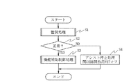
次に、上記第1の実施の形態の動作を、図4の制御演算装置23で実行される演算処理の処理手順の一例を示すフローチャートに基づいて説明する。
制御演算装置23では、まず、インバータ24の各電界効果トランジスタQua〜Qwbが正常に動作しているかどうか、また、インバータ24及び3相ブラシレスモータ12間の接続ラインにおいて地絡やライン間ショートが生じていないか等の異常監視を行うための監視処理を、公知の手順(例えば、特許第3550978号明細書に記載された異常検出処理の処理手順)で行う(ステップS1)。なお、前記閉回路開放用の電界効果トランジスタFETu〜FETwは起動時に導通状態に制御される。
Next, the operation of the first embodiment will be described based on a flowchart showing an example of a processing procedure of arithmetic processing executed by the control
In the control
ステップS1での監視処理の結果、異常が検出されなければ、ステップS2からステップS3に移行し、上述の公知の手順で操舵補助制御処理を実行する。そして、異常が検出されない間は、ステップS1からステップS2、ステップS3の処理を繰り返し行って、3相ブラシレスモータ12を駆動制御し、運転者により入力される操舵トルクに応じた操舵補助力を操舵系に付与し、運転者の操舵操作の操舵アシストを行い、運転者の操舵負荷の軽減を図る。
If no abnormality is detected as a result of the monitoring process in step S1, the process proceeds from step S2 to step S3, and the steering assist control process is executed in the above-described known procedure. While no abnormality is detected, the processes from step S1 to step S2 and step S3 are repeated to control the driving of the three-
一方、ステップS1での監視処理の結果、短絡異常、或いは、電界効果トランジスタQua〜Qwbのオン異常等、何らかの異常を検出した場合には、ステップS2からステップS4に移行し、3相ブラシレスモータ12を停止させ、操舵アシストを停止する。また、開放用FET駆動回路27に、3相ブラシレスモータ12の各励磁コイルLu〜Lwに設けた閉回路開放用の電界効果トランジスタFETu〜FETwを開放状態に切り換えるための制御信号を出力する。これによって、開放用FET駆動回路27は、前記電界効果トランジスタFETu〜FETwに対して、これを開放状態に切り換えるためのゲート電流を出力し、電界効果トランジスタFETu〜FETwは開放状態に切り換わる。
On the other hand, as a result of the monitoring process in step S1, if any abnormality is detected, such as a short circuit abnormality or field effect transistors Qua to Qwb on abnormality, the process proceeds from step S2 to step S4, and the three-
ここで、例えば、図5の概略図に示すように、インバータ24と3相ブラシレスモータ12のW相の励磁コイルLwとの間を接続する接続ラインの途中で地絡故障が生じた場合、W相の励磁コイルLw、V相の励磁コイルLv、インバータ24の電界効果トランジスタQvb及びこれと逆並列に接続されたダイオードがアースを介して導通される閉回路が形成されることになる。
Here, for example, as shown in the schematic diagram of FIG. 5, when a ground fault occurs in the middle of the connection line connecting the
この地絡異常を検出したときには、制御演算装置23では、図4のステップS1からステップS2を経てステップS4に移行し、3相ブラシレスモータ12の制御を停止すると共に、3相ブラシレスモータ12の閉回路開放用の電界効果トランジスタFETu〜FETwを開放状態に切り換える。このため、励磁コイルLwから中性点に流れ込む電流はダイオードDwを介して流れるが、中性点から励磁コイルLvに流れ出る電流はダイオードDvによって阻止される。逆に、励磁コイルLvから中性点に流れ込む電流はダイオードDvを介して流れるが、中性点から励磁コイルLwに流れ出る電流はダイオードDwによって阻止される。したがって、閉回路の形成が回避されることになる。
When this ground fault abnormality is detected, the control
また、例えば図6の概略図に示すように、インバータ24及び3相ブラシレスモータ12のV相及びW相の励磁コイルLv及びLwとの間を接続する接続ライン間でライン間ショートが発生した場合、W相の励磁コイルLw及びV相の励磁コイルLvが、ショートした接続ラインを介して導通される閉回路が形成されることになる。しかしながら、この場合も3相ブラシレスモータ12の開回路開放用の電界効果トランジスタFETu〜FETwを開放状態に切り換えることにより、ダイオードDv、Dwによって電流の流れが阻止されることから閉回路の形成を回避することができる。
Further, for example, as shown in the schematic diagram of FIG. 6, when a short circuit occurs between the connection lines connecting the V phase and W phase excitation coils Lv and Lw of the
ここで、インバータ24と3相ブラシレスモータ12とを接続するための接続ラインにおいてライン間ショートが発生した場合、例えば、ライン間ショートの発生地点とインバータ24との間に閉回路開放用のスイッチ回路を設けた場合には、接続ラインそれぞれにスイッチ回路を設けたとしても、閉回路の形成を回避することはできない。しかしながら、上記第1の実施の形態においては、閉回路開放用のスイッチ回路SWu〜SWwを、3相ブラシレスモータ12のモータハウジング101内に設けているから、インバータ24と3相ブラシレスモータ12とを接続するための接続ラインにおいてライン間ショートが発生した場合であっても、確実に閉回路の形成を回避することができる。
Here, when a line-to-line short circuit occurs in the connection line for connecting the
また、上述のように、ライン間ショートや地絡等の発生位置よりもインバータ24側に閉回路開放用のスイッチ回路を設けた場合には、これらスイッチ回路を作動させたとしても閉回路の形成を回避することができない可能性があるが、3相ブラシレスモータ12のモータハウジング101内においては、ライン間ショートや、地絡異常等が生じ難い環境にあるから、3相ブラシレスモータ12のモータハウジング101内に、閉回路開放用のスイッチ回路SWu〜SWwを設けることによって、閉回路の形成を確実に回避することができる。
In addition, as described above, when a switch circuit for opening a closed circuit is provided closer to the
また、上述のように、閉回路開放用の電界効果トランジスタFETu〜FETwを、その電流の流れが中性点に対して同一方向となる向きに配置し、且つ電界効果トランジスタFETu〜FETwのそれぞれにダイオードDu〜Dwを逆並列に接続している。したがって、各励磁コイルにおいては、一方向の電流の流れのみ阻止し、他方向の電流の流れは許容するが、この許容した電流の流れは、他の励磁コイルのダイオードによって阻止することができるため、3つの電界効果トランジスタFETu〜FETwと、3つのダイオードとで両方向の電流の流れを阻止することができる。つまり、3つの制御素子(電界効果トランジスタFETu〜FETw)を用いることで双方向の電流の流れを確実に遮断することができるから、その分、制御素子を駆動するための駆動回路を簡素化することができ、部品点数やコストの削減等を図ることができる。また、スイッチ回路SWu〜SWwをモータハウジング101内部に設けるという点からも、熱源となる電界効果トランジスタFETの数を低減できるということは効果的である。
Further, as described above, the field effect transistors FETu to FETw for opening the closed circuit are arranged in the direction in which the current flow is in the same direction with respect to the neutral point, and the field effect transistors FETu to FETw are respectively provided. Diodes Du to Dw are connected in antiparallel. Therefore, in each exciting coil, only the current flow in one direction is blocked and the current flow in the other direction is allowed, but this allowed current flow can be blocked by the diode of the other exciting coil. The three field effect transistors FETu to FETw and the three diodes can block the flow of current in both directions. That is, by using the three control elements (field effect transistors FETu to FETw), the bidirectional current flow can be reliably interrupted, and accordingly, the drive circuit for driving the control elements is simplified. Therefore, the number of parts and cost can be reduced. Further, from the viewpoint of providing the switch circuits SWu to SWw in the
また、上述のように、異常を検出した場合には、各励磁コイルに設けた閉回路開放用の電界効果トランジスタFETu〜FETwを全て開放状態に切り換えて中性点を開放しているから、どのような閉回路が形成される場合であってもこの閉回路の形成を確実に回避することができる。
また、上述のように、電界効果トランジスタFETu〜FETwは、低オン抵抗特性を有する炭化珪素を素材とした電界効果トランジスタであり、その発熱量は比較的小さく、また耐熱性にも優れていることから、電界効果トランジスタFETu〜FETwを3相ブラシレスモータ12のモータハウジング101内に設けた場合であっても何ら問題ない。
In addition, as described above, when an abnormality is detected, all the field effect transistors FETu to FETw for opening the closed circuit provided in the respective excitation coils are switched to the open state to open the neutral point. Even when such a closed circuit is formed, the formation of the closed circuit can be reliably avoided.
In addition, as described above, the field effect transistors FETu to FETw are field effect transistors made of silicon carbide having low on-resistance characteristics, and their heat generation is relatively small and excellent in heat resistance. Thus, there is no problem even if the field effect transistors FETu to FETw are provided in the
また、このように、閉回路開放用の電界効果トランジスタは、モータコイルの過熱や、電界効果トランジスタの発熱量等に対し、ある程度許容することができるから、この閉回路開放用の電界効果トランジスタをモータハウジング内に設けた場合であっても、その熱対策のための放熱構造を設ける必要はない。
また、閉回路開放用のスイッチ回路SWu〜SWwを、既存の回路基板102上に設けているから、大幅な変更を伴うことなく容易に実現することができる。
Further, in this way, the field effect transistor for opening the closed circuit can tolerate to some extent against overheating of the motor coil, the amount of heat generated by the field effect transistor, etc. Even when it is provided in the motor housing, it is not necessary to provide a heat dissipation structure for countermeasures against the heat.
Further, since the switch circuits SWu to SWw for opening the closed circuit are provided on the existing
また、スイッチ回路SWu〜SWwを、機械的接点を持たないスイッチング手段で構成しているから、起動時や、地絡、短絡異常発生時等、電界効果トランジスタFETu〜FETwを動作させた場合であってもその動作音が発生することはない。また、機械的接点を用いた場合の異物混入による導通異常や、溶着等が発生することはないから、機械的接点を用いた場合に比較して、より確実に閉回路の形成を回避することができ、電動パワーステアリング制御装置の信頼性を向上させることができる。 In addition, since the switch circuits SWu to SWw are configured by switching means having no mechanical contacts, the field effect transistors FETu to FETw are operated at the time of start-up, ground fault, short circuit abnormality, etc. However, the operation sound does not occur. Also, since there is no conduction abnormality or welding due to contamination by foreign matter when using mechanical contacts, avoid the formation of closed circuits more reliably than when mechanical contacts are used. The reliability of the electric power steering control device can be improved.
次に、本発明の第2の実施の形態を説明する。
この第2の実施の形態は、上記第1の実施の形態において、前記制御演算装置23において実行される演算処理の処理手順が異なること以外は同様であるので、同一部の詳細な説明は省略する。
この第2の実施の形態では、制御演算装置23は、図7のフローチャートに示す手順で演算処理を行う。
Next, a second embodiment of the present invention will be described.
Since the second embodiment is the same as the first embodiment except that the processing procedure of the arithmetic processing executed in the control
In the second embodiment, the control
まず、上記第1の実施の形態と同様に、インバータ24の各電界効果トランジスタQua〜Qwbが正常に動作しているかどうか、また地絡、短絡異常等が生じていないかどうかの監視を行い(ステップS1)、異常がなければステップS2からステップS3に移行し、公知の手順で通常の操舵補助制御処理を実行し、運転者の操舵トルクに応じて3相ブラシレスモータ12を駆動させ、操舵トルクに応じた操舵補助力を発生させて運転者の操舵アシストを行い、運転者の操舵負荷の軽減を図る。
First, as in the first embodiment, it is monitored whether or not each field effect transistor Qua to Qwb of the
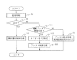
一方、監視処理で何らかの異常を検出した場合には、ステップS1からステップS2を経てステップS11に移行し、操舵アシストが継続可能かどうかを判断する。
つまり、図8の概略図に示すように、3相ブラシレスモータ12のW相の励磁コイルLwとインバータ24との間で地絡異常が発生した場合、上述のように、W相の励磁コイルLw、V相の励磁コイルLv、インバータ24の電界効果トランジスタQvb及びこれと逆並列に接続されたダイオードが、アースを介して導通されて閉回路が形成されることになる。この閉回路は、励磁コイルLwの電界効果トランジスタFETwを開放状態にすることによってその形成を回避することができ、U相及びV相の励磁コイルLu、Lvの電界効果トランジスタFETu及びFETvを導通状態のままとすることで、制御精度は低下するものの3相ブラシレスモータ12を駆動制御することができる。そこで、このように、何らかの異常が発生しているため制御精度は低下するものの、3相ブラシレスモータ12を引き続き駆動制御することができる状態にある場合には、操舵アシストを継続可能と判断する。
On the other hand, if any abnormality is detected in the monitoring process, the process proceeds from step S1 to step S11 through step S2, and it is determined whether or not the steering assist can be continued.
That is, as shown in the schematic diagram of FIG. 8, when a ground fault abnormality occurs between the W-phase excitation coil Lw of the three-
この判断は、例えば発生すると予測される異常について、この異常が発生したときに操舵アシストを継続可能であるかどうかを予め検出しておき、これに基づき、実際に発生した異常が、操舵アシストは継続可能として設定されているかどうかを判断することで、操舵アシストが継続可能かどうかを判断する。
そして、操舵アシストの継続は不可と判断される場合には、ステップS11からステップS4に移行し、上記第1の実施の形態と同様にアシスト停止処理を行って3相ブラシレスモータ12を停止させると共に、各励磁コイルLu〜Lwに設けた閉回路開放用の電界効果トランジスタFETu〜FETwを開放状態に切り換える。これによって、各励磁コイルLu〜Lwの中性点が開放されるから、どのような閉回路が形成される場合であってもその形成を回避することができる。
For example, for this abnormality that is predicted to occur, it is detected in advance whether or not the steering assist can be continued when this abnormality occurs. It is determined whether or not the steering assist can be continued by determining whether or not it is set as continuable.
If it is determined that the steering assist cannot be continued, the process proceeds from step S11 to step S4, and the assist stop process is performed to stop the three-
一方、前記ステップS1の監視処理で検出された異常が、すなわち図8に示すように、3相ブラシレスモータ12のW相の励磁コイルLwとインバータ24とを接続する接続ラインの途中での地絡異常の場合には、励磁コイルLwの閉回路開放用の電界効果トランジスタFETwを開放状態に切り換えることによって、閉回路の形成を回避することができ、さらに、励磁コイルLu及びLvを用いることで、3相ブラシレスモータ12を継続して駆動制御することができる。
On the other hand, the abnormality detected in the monitoring process in step S1, that is, as shown in FIG. 8, a ground fault in the middle of the connection line connecting the W-phase exciting coil Lw of the three-
したがって、図8に示すような地絡異常が発生した場合には、操舵アシストを継続可能と判断し、ステップS11からステップS12に移行し、発生した異常による閉回路の形成を回避し得る、開放状態に制御すべき閉回路開放用の電界効果トランジスタを特定する。
この開放状態に制御すべき電界効果トランジスタの特定は、発生すると予測される異常のうち、この異常が発生しても操舵アシストを継続可能な異常について、どの励磁コイルを開放状態にすれば、閉回路の形成を回避し且つ操舵アシストを継続することが可能であるかを予め検出しておき、これに基づき、実際に発生した異常に対応する、閉回路開放用の電界効果トランジタを検索すればよい。
Therefore, when a ground fault abnormality as shown in FIG. 8 occurs, it is determined that the steering assist can be continued, the process proceeds from step S11 to step S12, and the formation of a closed circuit due to the generated abnormality can be avoided. A field effect transistor for opening a closed circuit to be controlled is specified.
The field effect transistor to be controlled to the open state is identified as to which of the abnormalities that are expected to occur and which can continue the steering assist even if this abnormality occurs, which excitation coil should be opened. If it is detected in advance whether it is possible to avoid the formation of the circuit and the steering assist can be continued, and based on this, the field effect transistor for opening the closed circuit corresponding to the actually occurring abnormality is searched. Good.
図8の地絡異常の場合には、開放状態(オフ状態)に制御すべき閉回路開放用の電界効果トランジスタとして、励磁コイルLwの電界効果トランジスタFETwが特定される。
次いで、ステップS13に移行し、ステップS12で特定した電界効果トランジスタを開放状態に切り換えた状態で3相ブラシレスモータ12の駆動制御を行う、アシスト継続処理を実行する。
In the case of the ground fault abnormality of FIG. 8, the field effect transistor FETw of the exciting coil Lw is specified as the closed circuit opening field effect transistor to be controlled to the open state (off state).
Next, the process proceeds to step S13, and an assist continuation process is performed in which the drive control of the three-
つまり、ステップS12で特定した電界効果トランジスタ、図8の地絡異常の場合には電界効果トランジスタFETwのみを開放状態に切り換える制御信号を、開放用FET駆動回路27に出力する。
これによって、開放用FET駆動回路27が動作し、U相及びV相の励磁コイルLu及Lvの電界効果トランジスタFETu及びFETvは導通状態のまま、W相の励磁コイルLwの電界効果トランジスタFETwのみが開放状態となる。
That is, a control signal for switching only the field effect transistor FETw specified in step S12 or the field effect transistor FETw to the open state in the case of the ground fault abnormality of FIG. 8 is output to the open
As a result, the open-circuit
また、制御演算装置23は、閉回路開放用の電界効果トランジスタFETwが開放状態に制御された励磁コイルを除いた残りの励磁コイルを用いて3相ブラシレスモータ12を駆動制御する。
つまり、図8に示す地絡異常の場合には、上述のように、励磁コイルLu及びLvを用いることで、3相ブラシレスモータ12を駆動制御することが可能であるから、励磁コイルLu及びLvのみを用いた、3相ブラシレスモータ12の駆動制御を行う。
In addition, the control
That is, in the case of the ground fault abnormality shown in FIG. 8, it is possible to drive and control the three-
この駆動制御は、例えば、発生すると予測される異常のうち、この異常が発生しても操舵アシストを継続可能な異常について、この操舵アシストを行う際のインバータ24の制御手順を予め設定しておき、発生した異常に対応する制御手順を用いてインバータ24を駆動制御すればよい。
図8の地絡異常が発生した場合には、励磁コイルLu及びLvのみを用いた制御を行うことから、インバータ24の電界効果トランジスタQwa及びQwbは開放状態に維持し、電界効果トランジスタQua、Qub、Qva、Qvbを、トルク検出値Tに応じて、アシスト力を正常時より抑えてPWM制御する。
In this drive control, for example, among the abnormalities that are predicted to occur, the control procedure of the
When the ground fault abnormality of FIG. 8 occurs, the control using only the exciting coils Lu and Lv is performed, so that the field effect transistors Qwa and Qwb of the
これによって、3相ブラシレスモータ12が駆動制御されることから、十分な操舵補助力を発生することができなかったり、また、滑らかな駆動制御を行うことができなかったりするものの、引き続き操舵補助力を発生することができ、運転者の操舵負荷の軽減を図ることができる。
特に、電動パワーステアリング制御装置はその大出力化が進んでいるため、電動パワーステアリング制御装置による操舵アシストが停止すると運転者の負担がかなり大きくなるが、上述のように、多少アシスト力が小さい状態であっても操舵アシストを継続することができるから有効である。
As a result, the three-
In particular, since the output of the electric power steering control device is increasing, when the steering assist by the electric power steering control device is stopped, the burden on the driver is considerably increased. However, as described above, the assist force is somewhat small. Even so, it is effective because the steering assist can be continued.
なお、閉回路の形成の回避に必要な閉回路開放用の電界効果トランジスタのみを開放状態に切り換え、引き続き操舵アシストを継続する場合、例えば、図8に示すように、励磁コイルLwの閉回路開放用の電界効果トランジスタFETwを開放状態に切り換えたとしても、励磁コイルLvの閉回路開放用の電界効果トランジスタFETvは導通状態のままであることから、励磁コイルLwのダイオードDwを経由した閉回路は形成されたままとなり、ダイオードDwを介して意図しない電流が流れる可能性がある。 When only the closed circuit opening field effect transistor necessary for avoiding the formation of the closed circuit is switched to the open state and the steering assist is continued, for example, as shown in FIG. 8, the closed circuit opening of the exciting coil Lw is opened. Even when the field effect transistor FETw for switching is switched to the open state, the field effect transistor FETv for opening the closed circuit of the exciting coil Lv remains in a conductive state, so that the closed circuit via the diode Dw of the exciting coil Lw is There is a possibility that an unintended current flows through the diode Dw.
しかしながら、このようにダイオードDwを経由して閉回路に電流が流れる状況は、例えば、急操舵して3相ブラシレスモータ12が発電機として動作する場合等に発生するが、必要最小限の操舵アシスト力となるように正常時よりも抑えてアシストを継続するため急操舵が困難となる。したがって、ダイオードDwを経由した電流は流れにくいことから、実際の運用上は何ら問題ない。
However, the situation where current flows through the closed circuit via the diode Dw as described above occurs, for example, when the three-
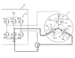
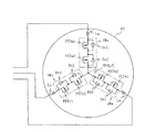
なお、このダイオードを介して閉回路に電流が流れることを回避するためには、例えば、図9に示すように、閉回路開放用スイッチ回路SWuを、ドレイン側どうし又はソース側どうしが接続された2つの閉回路開放用の電界効果トランジスタFETu1及びFETu2と、これらそれぞれに逆並列に接続されたダイオードDu1及びDu2とで構成し、同様に、閉回路開放用スイッチ回路SWv及びSWwも、ドレイン側どうし又はソース側どうしが接続された2つの閉回路開放用の電界効果トランジスタFETv1及びFETv2、FETw1及びFETw2と、これらそれぞれに逆並列に接続されたダイオードDv1及びDv2、ダイオードDw1及びDw2とで構成し、これら閉回路開放用スイッチ回路SWu〜SWwを、各励磁コイルLu〜Lwと3相ブラシレスモータ12の中性点との間に設ければよい。そいて、各励磁コイルLu〜Lwに設けられた2つの閉回路開放用の電界効果トランジスタを共に開放状態に切り換えることによって、この励磁コイルの双方向の電流の流れを阻止することができる。
In order to avoid a current from flowing through the diode to the closed circuit, for example, as shown in FIG. 9, the closed circuit opening switch circuit SWu is connected between the drain side or the source side. It is composed of two closed-circuit opening field effect transistors FETu1 and FETu2 and diodes Du1 and Du2 connected in antiparallel to each of them. Similarly, the closed-circuit opening switch circuits SWv and SWw are connected to each other on the drain side. Alternatively, two open-circuit field-effect transistors FETv1 and FETv2, FETw1 and FETw2 connected to each other on the source side, and diodes Dv1 and Dv2 and diodes Dw1 and Dw2 connected in antiparallel to each of them, These switch circuits SWu to SWw for opening the closed circuit are connected to each excitation core. It may be provided between the neutral point of the Le Lu~Lw and 3-
したがって、図8に示す地絡異常が発生した場合、励磁コイルLwの閉回路開放用の電界効果トランジスタFETw1及びFETw2を共に開放状態に切り換えることによって、励磁コイルLu及びLvは双方向の電流の流れを許容したまま、励磁コイルLwのみが他の励磁コイルLu及びLvから切り離されることになる。
このため、急操舵時等、3相ブラシレスモータ12が発電機として動作した場合であっても、不要な電流が閉回路を流れ、3相ブラシレスモータ12が電磁ブレーキとして動作することを確実に回避することができる。
Therefore, when the ground fault abnormality shown in FIG. 8 occurs, by switching both the field effect transistors FETw1 and FETw2 for opening the closed circuit of the exciting coil Lw to the open state, the exciting coils Lu and Lv flow bidirectionally. Only the exciting coil Lw is disconnected from the other exciting coils Lu and Lv.
For this reason, even when the three-
なお、上記各実施の形態においては、スター結線の3相ブラシレスモータにおいて、閉回路開放用の電界効果トランジスタをそのモータハウジング101内に設けた場合について説明したが、3相に限らず、単相、或いは多相のブラシレスモータ、また、Δ結線されたブラシレスモータにおいて、閉回路開放用の電界効果トランジスタをそのモータハウジング内に設けることも可能である。この場合も、上述のように、より確実に閉回路の形成を回避することができると共に、機械的接点を用いる場合に比較して、その作動音や抵抗等の影響の少ない、ブラシレスモータを実現することができる。
In each of the above embodiments, a case where a field effect transistor for opening a closed circuit is provided in the
また、上記実施の形態においては、電動パワーステアリング制御装置において操舵系に操舵補助力を付与するための3相ブラシレスモータに適用した場合について説明したが、これに限るものではなく、ブラシレスモータを用い、これを駆動制御するような制御装置であれば適用することができる。
ここで、上記実施の形態において、インバータ24及びFETゲート駆動回路26がモータ駆動回路に対応し、制御演算装置23が制御手段に対応し、スイッチ回路SWu〜SWwがスイッチング手段に対応し、図4及び図7のステップS1の処理が異常検出手段に対応している。
In the above embodiment, the case where the electric power steering control device is applied to a three-phase brushless motor for applying a steering assist force to the steering system has been described. However, the present invention is not limited to this, and a brushless motor is used. Any control device that drives and controls the above can be applied.
Here, in the above embodiment, the
また、図7のステップS11の処理が制御継続判定手段に対応し、ステップS12及びステップS13の処理が継続制御手段に対応している。
また、図9のFETu1及びDu1が第1のスイッチ回路に対応し、FETu2及びDu2が第2のスイッチ回路に対応している。同様に、FETv1及びDv1が第1のスイッチ回路に対応し、FETv2及びDv2が第2のスイッチ回路に対応し、FETw1及びDw1が第1のスイッチ回路に対応し、FETw2及びDw2が第2のスイッチ回路に対応している。
Moreover, the process of step S11 of FIG. 7 respond | corresponds to a control continuation determination means, and the process of step S12 and step S13 respond | corresponds to a continuation control means.
Further, the FETu1 and Du1 in FIG. 9 correspond to the first switch circuit, and the FETu2 and Du2 correspond to the second switch circuit. Similarly, FETv1 and Dv1 correspond to the first switch circuit, FETv2 and Dv2 correspond to the second switch circuit, FETw1 and Dw1 correspond to the first switch circuit, and FETw2 and Dw2 correspond to the second switch circuit. It corresponds to the circuit.
1 ステアリングホイール
2 ステアリングシャフト
3 操舵トルクセンサ
8 ステアリングギヤ
12 3相ブラシレスモータ
15 車速センサ
20 コントローラ
22 モータ電流検出回路
23 制御演算装置
24 インバータ
26 FETゲート駆動回路
27 開放用FET駆動回路
102 回路基板
DESCRIPTION OF
Claims (7)
当該ブラシレスモータ及び電源間に接続され且つ複数のスイッチング素子から構成されるインバータを備えたモータ駆動回路と、
当該モータ駆動回路を制御し前記ブラシレスモータを駆動制御する制御手段と、を備えたモータ制御装置において、
前記ブラシレスモータの励磁コイル毎に設けられ且つ前記ブラシレスモータのハウジング内部に配置される、低オン抵抗型の半導体素子からなる閉回路開放用のスイッチング手段と、
当該モータ制御装置の異常を検出する異常検出手段と、を備え、
前記制御手段は、前記異常検出手段で異常を検出したとき前記スイッチング手段を開放状態に切り換えることを特徴とするモータ制御装置。 A brushless motor,
A motor drive circuit including an inverter connected between the brushless motor and a power source and configured by a plurality of switching elements;
In a motor control device comprising a control means for controlling the motor drive circuit and controlling the drive of the brushless motor,
Switching means for opening a closed circuit made of a low on-resistance type semiconductor element, provided for each excitation coil of the brushless motor and disposed inside the housing of the brushless motor;
An abnormality detecting means for detecting an abnormality of the motor control device,
The motor control device characterized in that the control means switches the switching means to an open state when an abnormality is detected by the abnormality detection means.
前記スイッチング手段を前記ブラシレスモータの中性点と前記励磁コイルとの間に設け、且つ当該スイッチング手段を、前記中性点を形成した回路基板上に配置したことを特徴とする請求項1記載のモータ制御装置。 The brushless motor is a brushless motor in which excitation coils are star-connected,
The switching means is provided between a neutral point of the brushless motor and the excitation coil, and the switching means is disposed on a circuit board on which the neutral point is formed. Motor control device.
前記半導体素子は、全ての励磁コイルにおいて、前記半導体素子を流れる電流方向が、前記ブラシレスモータの中性点に対して同一となるように設けられ、
前記制御手段は、前記異常検出手段で異常を検出したとき、全ての励磁コイルの前記スイッチング手段を開放状態に切り換えることを特徴とする請求項2記載のモータ制御装置。 The switching means is composed of the semiconductor element and a diode connected in antiparallel to the semiconductor element,
The semiconductor element is provided in all exciting coils such that the direction of current flowing through the semiconductor element is the same as the neutral point of the brushless motor,
3. The motor control device according to claim 2, wherein when the abnormality is detected by the abnormality detection means, the control means switches the switching means of all the excitation coils to an open state.
当該制御継続判定手段で前記ブラシレスモータを継続制御可能と判定されるとき、前記ブラシレスモータを継続制御可能とし得るスイッチング手段を開放状態に切り換えると共に、当該スイッチング手段を開放状態に切り換えた状態で前記ブラシレスモータを駆動するための継続制御を行う継続制御手段と、を備えることを特徴とする請求項3記載のモータ制御装置。 The control means switches an unintentional closing accompanying the occurrence of the abnormality by switching any of the switching means provided in each excitation coil to an open state based on the content of the abnormality detected by the abnormality detecting means. Control continuation determining means for determining whether the brushless motor can be controlled in a state in which formation of a circuit is avoided and the switching means is switched to an open state;
When it is determined by the control continuation determining means that the brushless motor can be continuously controlled, the switching means capable of continuously controlling the brushless motor is switched to the open state, and the brushless motor is switched to the open state. The motor control device according to claim 3, further comprising: a continuation control unit that performs continuation control for driving the motor.
前記制御手段は、前記異常検出手段で検出した異常の内容に基づいて、各励磁コイルに設けられた前記スイッチング手段のうちの何れかを開放状態に切り換えることにより前記異常の発生に伴う意図しない閉回路の形成を回避し、且つ前記スイッチング手段を開放状態に切り換えた状態で前記ブラシレスモータを制御可能かどうか判定する制御継続判定手段と、
当該制御継続判定手段で前記ブラシレスモータを継続制御可能と判定されるとき、前記ブラシレスモータを継続制御可能とし得るスイッチング手段を開放状態に切り換えると共に、当該スイッチング手段を開放状態に切り換えた状態で前記ブラシレスモータを駆動するための継続制御を行う継続制御手段と、を備えることを特徴とする請求項2記載のモータ制御装置。 The switching means includes the first switch circuit including the semiconductor element, a diode connected in antiparallel to the semiconductor element, and a second switch circuit having the same configuration as the first switch circuit, and the first switch circuit. And the second switch circuit is connected in series so that the direction of current flow between the semiconductor elements is opposite,
The control means switches an unintentional closing accompanying the occurrence of the abnormality by switching any of the switching means provided in each excitation coil to an open state based on the content of the abnormality detected by the abnormality detecting means. Control continuation determining means for determining whether the brushless motor can be controlled in a state in which formation of a circuit is avoided and the switching means is switched to an open state;
When it is determined by the control continuation determining means that the brushless motor can be continuously controlled, the switching means capable of continuously controlling the brushless motor is switched to the open state, and the brushless motor is switched to the open state. The motor control device according to claim 2, further comprising: a continuation control unit that performs continuation control for driving the motor.
Priority Applications (1)
| Application Number | Priority Date | Filing Date | Title |
|---|---|---|---|
| JP2006117786A JP2007295658A (en) | 2006-04-21 | 2006-04-21 | Motor controller and motor-driven power steering controller employing the same |
Applications Claiming Priority (1)
| Application Number | Priority Date | Filing Date | Title |
|---|---|---|---|
| JP2006117786A JP2007295658A (en) | 2006-04-21 | 2006-04-21 | Motor controller and motor-driven power steering controller employing the same |
Publications (1)
| Publication Number | Publication Date |
|---|---|
| JP2007295658A true JP2007295658A (en) | 2007-11-08 |
Family
ID=38765742
Family Applications (1)
| Application Number | Title | Priority Date | Filing Date |
|---|---|---|---|
| JP2006117786A Pending JP2007295658A (en) | 2006-04-21 | 2006-04-21 | Motor controller and motor-driven power steering controller employing the same |
Country Status (1)
| Country | Link |
|---|---|
| JP (1) | JP2007295658A (en) |
Cited By (20)
| Publication number | Priority date | Publication date | Assignee | Title |
|---|---|---|---|---|
| JP2009220705A (en) * | 2008-03-17 | 2009-10-01 | Jtekt Corp | Steering controlling device |
| JP2009262648A (en) * | 2008-04-23 | 2009-11-12 | Jtekt Corp | Steering control device |
| JP2010093940A (en) * | 2008-10-07 | 2010-04-22 | Denso Corp | Power supply circuit and signal detection apparatus |
| JP2011068204A (en) * | 2009-09-24 | 2011-04-07 | Mitsubishi Electric Corp | Motor device for electric power steering device |
| WO2011089656A1 (en) * | 2010-01-25 | 2011-07-28 | トヨタ自動車株式会社 | Motor drive system, motor drive system control method and travelling device |
| WO2012114901A1 (en) * | 2011-02-25 | 2012-08-30 | Ntn株式会社 | Electric automobile, in-wheel motor drive device, and motor control method |
| JP2012178914A (en) * | 2011-02-25 | 2012-09-13 | Ntn Corp | Electric vehicle |
| US20130141871A1 (en) * | 2010-11-02 | 2013-06-06 | Mitsubishi Electric Corporation | Power module for electric power steering and electric power steering drive control apparatus using the same |
| WO2013140906A1 (en) * | 2012-03-22 | 2013-09-26 | 日立オートモティブシステムズ株式会社 | Power conversion device, electric power steering system, electric vehicle, electronic control throttle, and electric brake |
| JP2013209089A (en) * | 2013-05-20 | 2013-10-10 | Jtekt Corp | Steering control device |
| JP2014180105A (en) * | 2013-03-14 | 2014-09-25 | Hitachi Automotive Systems Ltd | Drive control device of motor |
| WO2014184888A1 (en) * | 2013-05-15 | 2014-11-20 | 三菱電機株式会社 | Electric power steering device |
| WO2015015878A1 (en) * | 2013-08-02 | 2015-02-05 | 日立オートモティブシステムズ株式会社 | Power conversion device, electric power steering system, electric vehicle, electronic control throttle, and electric brake |
| JP2015033242A (en) * | 2013-08-02 | 2015-02-16 | 日立オートモティブシステムズ株式会社 | Motor drive control device |
| JP2017047778A (en) * | 2015-09-01 | 2017-03-09 | トヨタ自動車株式会社 | Electric power steering apparatus |
| JP2017047777A (en) * | 2015-09-01 | 2017-03-09 | トヨタ自動車株式会社 | Electric power steering apparatus |
| US9751409B2 (en) | 2011-02-25 | 2017-09-05 | Ntn Corporation | Electric automobile |
| WO2017153110A1 (en) * | 2016-03-10 | 2017-09-14 | Zf Friedrichshafen Ag | Method and device for actuating a three-phase drive device, drive device, and roll stabilizer |
| WO2021065581A1 (en) * | 2019-10-04 | 2021-04-08 | 日立Astemo株式会社 | Motor drive device |
| US11136062B2 (en) | 2015-07-27 | 2021-10-05 | Trw Limited | Control for electric power steering |
-
2006
- 2006-04-21 JP JP2006117786A patent/JP2007295658A/en active Pending
Cited By (41)
| Publication number | Priority date | Publication date | Assignee | Title |
|---|---|---|---|---|
| JP2009220705A (en) * | 2008-03-17 | 2009-10-01 | Jtekt Corp | Steering controlling device |
| US8541967B2 (en) | 2008-04-23 | 2013-09-24 | Jtekt Corporation | Steering control apparatus |
| JP2009262648A (en) * | 2008-04-23 | 2009-11-12 | Jtekt Corp | Steering control device |
| US8907603B2 (en) | 2008-04-23 | 2014-12-09 | Jtekt Corporation | Steering control apparatus |
| US8053936B2 (en) | 2008-10-07 | 2011-11-08 | Denso Corporation | Power supply circuit and signal detection apparatus |
| JP2010093940A (en) * | 2008-10-07 | 2010-04-22 | Denso Corp | Power supply circuit and signal detection apparatus |
| JP4666045B2 (en) * | 2008-10-07 | 2011-04-06 | 株式会社デンソー | Signal detection device |
| JP2011068204A (en) * | 2009-09-24 | 2011-04-07 | Mitsubishi Electric Corp | Motor device for electric power steering device |
| WO2011089656A1 (en) * | 2010-01-25 | 2011-07-28 | トヨタ自動車株式会社 | Motor drive system, motor drive system control method and travelling device |
| CN102687389B (en) * | 2010-01-25 | 2015-04-29 | 丰田自动车株式会社 | Motor drive system, motor drive system control method and travelling device |
| CN102687389A (en) * | 2010-01-25 | 2012-09-19 | 丰田自动车株式会社 | Motor drive system, motor drive system control method and travelling device |
| JP5459311B2 (en) * | 2010-01-25 | 2014-04-02 | トヨタ自動車株式会社 | Motor drive system, motor drive system control method, and travel device |
| US8575885B2 (en) | 2010-01-25 | 2013-11-05 | Toyota Jidosha Kabushiki Kaisha | Motor drive system, control method of motor drive system, and traveling device |
| US9888613B2 (en) * | 2010-11-02 | 2018-02-06 | Mitsubishi Electric Corporation | Power module for electric power steering and electric power steering drive control apparatus using the same |
| CN109194153A (en) * | 2010-11-02 | 2019-01-11 | 三菱电机株式会社 | Electric power steering power module and the electric power steering drive dynamic control device for using it |
| US20130141871A1 (en) * | 2010-11-02 | 2013-06-06 | Mitsubishi Electric Corporation | Power module for electric power steering and electric power steering drive control apparatus using the same |
| JPWO2012060123A1 (en) * | 2010-11-02 | 2014-05-12 | 三菱電機株式会社 | Power module for electric power steering and electric power steering drive control apparatus using the same |
| JP5970668B2 (en) * | 2010-11-02 | 2016-08-17 | 三菱電機株式会社 | Power module for electric power steering and electric power steering drive control apparatus using the same |
| JP2015039295A (en) * | 2010-11-02 | 2015-02-26 | 三菱電機株式会社 | Power module for motor-driven power steering and motor-driven power steering drive control apparatus using the power module |
| US9751409B2 (en) | 2011-02-25 | 2017-09-05 | Ntn Corporation | Electric automobile |
| JP2012178914A (en) * | 2011-02-25 | 2012-09-13 | Ntn Corp | Electric vehicle |
| WO2012114901A1 (en) * | 2011-02-25 | 2012-08-30 | Ntn株式会社 | Electric automobile, in-wheel motor drive device, and motor control method |
| CN103384615B (en) * | 2011-02-25 | 2016-02-10 | Ntn株式会社 | Electronlmobil, interiorly take turns motor drive and method of motor control |
| US9252590B2 (en) | 2011-02-25 | 2016-02-02 | Ntn Corporation | Electric automobile, in-wheel motor drive device, and motor control method |
| US9490732B2 (en) | 2012-03-22 | 2016-11-08 | Hitachi Automotive Systems, Ltd. | Power conversion apparatus, electronic steering system, electric vehicle, electronic control throttle and power brake |
| WO2013140906A1 (en) * | 2012-03-22 | 2013-09-26 | 日立オートモティブシステムズ株式会社 | Power conversion device, electric power steering system, electric vehicle, electronic control throttle, and electric brake |
| JPWO2013140906A1 (en) * | 2012-03-22 | 2015-08-03 | 日立オートモティブシステムズ株式会社 | Power converter, electric power steering system, electric vehicle, electronic control throttle, electric brake |
| JP2014180105A (en) * | 2013-03-14 | 2014-09-25 | Hitachi Automotive Systems Ltd | Drive control device of motor |
| WO2014184888A1 (en) * | 2013-05-15 | 2014-11-20 | 三菱電機株式会社 | Electric power steering device |
| JP2013209089A (en) * | 2013-05-20 | 2013-10-10 | Jtekt Corp | Steering control device |
| WO2015015878A1 (en) * | 2013-08-02 | 2015-02-05 | 日立オートモティブシステムズ株式会社 | Power conversion device, electric power steering system, electric vehicle, electronic control throttle, and electric brake |
| CN105409112A (en) * | 2013-08-02 | 2016-03-16 | 日立汽车系统株式会社 | Power conversion device, electric power steering system, electric vehicle, electronic control throttle, and electric brake |
| US9882522B2 (en) | 2013-08-02 | 2018-01-30 | Hitachi Automotive Systems, Ltd. | Power conversion device, electric power steering system, electric vehicle, electronic control throttle, and electric brake |
| JP2015033212A (en) * | 2013-08-02 | 2015-02-16 | 日立オートモティブシステムズ株式会社 | Power conversion device, electric power steering system, electric vehicle, electronic control throttle, and electric brake |
| CN105409112B (en) * | 2013-08-02 | 2018-06-08 | 日立汽车系统株式会社 | Power-converting device, electric boosting steering system, electric vehicle, electronic control throttle, dynamo-electric brake |
| JP2015033242A (en) * | 2013-08-02 | 2015-02-16 | 日立オートモティブシステムズ株式会社 | Motor drive control device |
| US11136062B2 (en) | 2015-07-27 | 2021-10-05 | Trw Limited | Control for electric power steering |
| JP2017047778A (en) * | 2015-09-01 | 2017-03-09 | トヨタ自動車株式会社 | Electric power steering apparatus |
| JP2017047777A (en) * | 2015-09-01 | 2017-03-09 | トヨタ自動車株式会社 | Electric power steering apparatus |
| WO2017153110A1 (en) * | 2016-03-10 | 2017-09-14 | Zf Friedrichshafen Ag | Method and device for actuating a three-phase drive device, drive device, and roll stabilizer |
| WO2021065581A1 (en) * | 2019-10-04 | 2021-04-08 | 日立Astemo株式会社 | Motor drive device |
Similar Documents
| Publication | Publication Date | Title |
|---|---|---|
| JP2007295658A (en) | Motor controller and motor-driven power steering controller employing the same | |
| JP5569626B1 (en) | Motor control device, electric power steering device using the same, and vehicle | |
| JP5229645B2 (en) | Electric motor drive device and electric power steering device using the same | |
| US8981691B2 (en) | Motor drive apparatus | |
| JP5195888B2 (en) | Electric motor drive device and electric power steering device using the same | |
| EP3193443B1 (en) | Inverter device for driving multi-phase ac motor | |
| JP5672936B2 (en) | Electric power steering device | |
| WO2010032705A1 (en) | Motor controller and electric power steering device | |
| JP5070867B2 (en) | Motor control device and electric power steering device | |
| JP2009035155A (en) | Electric power steering device | |
| JP5833360B2 (en) | Motor control device and vehicle steering device | |
| JP2016019330A (en) | Controller of rotary machine | |
| JP2014176215A (en) | Motor control device, electrically-driven power steering apparatus employing the same and vehicle | |
| WO2007129359A1 (en) | Electric motor control apparatus | |
| JP5945740B2 (en) | Power steering device | |
| JP2008211910A (en) | Motor control device and electric power steering device | |
| JP2008211909A (en) | Motor control device and electric power steering device | |
| JP6177426B2 (en) | AC rotating machine control device and electric power steering device | |
| JP2013048524A (en) | Control device of multi-phase rotary machine | |
| JP4644013B2 (en) | Electric power steering device | |
| JP6096080B2 (en) | Motor drive control device | |
| JP2010137627A (en) | Electric power steering device | |
| JP2007223436A (en) | Relay circuit and electric power steering control device using the same | |
| JP2014091454A (en) | Electric power steering system | |
| JP5131435B2 (en) | Electric power steering device |
Legal Events
| Date | Code | Title | Description |
|---|---|---|---|
| RD01 | Notification of change of attorney |
Free format text: JAPANESE INTERMEDIATE CODE: A7421 Effective date: 20090130 |