JP2010092755A - Light guide plate - Google Patents
Light guide plate Download PDFInfo
- Publication number
- JP2010092755A JP2010092755A JP2008262687A JP2008262687A JP2010092755A JP 2010092755 A JP2010092755 A JP 2010092755A JP 2008262687 A JP2008262687 A JP 2008262687A JP 2008262687 A JP2008262687 A JP 2008262687A JP 2010092755 A JP2010092755 A JP 2010092755A
- Authority
- JP
- Japan
- Prior art keywords
- guide plate
- light
- light guide
- fine particles
- refractive index
- Prior art date
- Legal status (The legal status is an assumption and is not a legal conclusion. Google has not performed a legal analysis and makes no representation as to the accuracy of the status listed.)
- Granted
Links
Images
Classifications
-
- G—PHYSICS
- G02—OPTICS
- G02B—OPTICAL ELEMENTS, SYSTEMS OR APPARATUS
- G02B6/00—Light guides; Structural details of arrangements comprising light guides and other optical elements, e.g. couplings
- G02B6/0001—Light guides; Structural details of arrangements comprising light guides and other optical elements, e.g. couplings specially adapted for lighting devices or systems
- G02B6/0011—Light guides; Structural details of arrangements comprising light guides and other optical elements, e.g. couplings specially adapted for lighting devices or systems the light guides being planar or of plate-like form
- G02B6/0033—Means for improving the coupling-out of light from the light guide
- G02B6/0035—Means for improving the coupling-out of light from the light guide provided on the surface of the light guide or in the bulk of it
- G02B6/004—Scattering dots or dot-like elements, e.g. microbeads, scattering particles, nanoparticles
- G02B6/0041—Scattering dots or dot-like elements, e.g. microbeads, scattering particles, nanoparticles provided in the bulk of the light guide
-
- G—PHYSICS
- G02—OPTICS
- G02F—OPTICAL DEVICES OR ARRANGEMENTS FOR THE CONTROL OF LIGHT BY MODIFICATION OF THE OPTICAL PROPERTIES OF THE MEDIA OF THE ELEMENTS INVOLVED THEREIN; NON-LINEAR OPTICS; FREQUENCY-CHANGING OF LIGHT; OPTICAL LOGIC ELEMENTS; OPTICAL ANALOGUE/DIGITAL CONVERTERS
- G02F1/00—Devices or arrangements for the control of the intensity, colour, phase, polarisation or direction of light arriving from an independent light source, e.g. switching, gating or modulating; Non-linear optics
- G02F1/01—Devices or arrangements for the control of the intensity, colour, phase, polarisation or direction of light arriving from an independent light source, e.g. switching, gating or modulating; Non-linear optics for the control of the intensity, phase, polarisation or colour
- G02F1/13—Devices or arrangements for the control of the intensity, colour, phase, polarisation or direction of light arriving from an independent light source, e.g. switching, gating or modulating; Non-linear optics for the control of the intensity, phase, polarisation or colour based on liquid crystals, e.g. single liquid crystal display cells
- G02F1/133—Constructional arrangements; Operation of liquid crystal cells; Circuit arrangements
- G02F1/1333—Constructional arrangements; Manufacturing methods
- G02F1/1335—Structural association of cells with optical devices, e.g. polarisers or reflectors
- G02F1/1336—Illuminating devices
- G02F1/133602—Direct backlight
- G02F1/133606—Direct backlight including a specially adapted diffusing, scattering or light controlling members
Abstract
Description
この発明は、光散乱のための微粒子を含有しつつも黄色度が十分に抑制された導光板に関する。 The present invention relates to a light guide plate that contains fine particles for light scattering and has sufficiently suppressed yellowness.
液晶表示装置や照明装置等のバックライトとしては、例えば導光板の側方に冷陰極ランプを配置し、該冷陰極ランプからの光を導光板背面に形成されたドットパターンやプリズム部等により反射させて導光板前面から光を均一に出射できるように構成したものが公知である。 As a backlight of a liquid crystal display device or a lighting device, for example, a cold cathode lamp is disposed on the side of a light guide plate, and light from the cold cathode lamp is reflected by a dot pattern or a prism portion formed on the back surface of the light guide plate. It is known that the light can be uniformly emitted from the front surface of the light guide plate.
このようなバックライト用の導光板としては、アクリル系樹脂等の透明樹脂中に微粒子が分散されてなる導光板が公知であり、この導光板は、微粒子の含有によって光散乱させることができて輝度均一性に優れている(特許文献1参照)。
しかしながら、上記のような透明樹脂中に微粒子が分散されてなる導光板は、透過光が少し黄色味を帯びやすく(YI値が大きく)、この導光板を用いて構成された液晶表示装置は、画像が僅かに黄色味を帯びていて高品位な画像が得られないという問題があった。即ち、自然で高品位なカラー表示を実現できないという問題があった。 However, the light guide plate in which the fine particles are dispersed in the transparent resin as described above, the transmitted light is slightly yellowish (large YI value), and the liquid crystal display device configured using this light guide plate is There was a problem that the image was slightly yellowish and a high-quality image could not be obtained. That is, there is a problem that a natural and high-quality color display cannot be realized.
この発明は、かかる技術的背景に鑑みてなされたものであって、光散乱のための微粒子を含有させるものでありながら黄色度が十分に抑制された光を出射できる導光板及び白色度の高い光を出射できる面光源装置並びに自然で高品位なカラー表示を実現できる液晶表示装置を提供することを目的とする。 The present invention has been made in view of such technical background, and includes a light guide plate capable of emitting light with sufficiently suppressed yellowness while containing fine particles for light scattering, and high whiteness. An object of the present invention is to provide a surface light source device capable of emitting light and a liquid crystal display device capable of realizing a natural and high-quality color display.
前記目的を達成するために、本発明者は鋭意検討した結果、
1)微粒子の累積50%粒子径D50(μm)
2)透明樹脂の屈折率と微粒子の屈折率の差の絶対値Δn
3)300mmの光路長でのYI(イエローインデックス)
これら相互の間に関連性があることを見出し、この関連性に着目してさらに鋭意研究した結果、0.30≦Δn×D50≦0.70の関係式が成立する場合において、出射光のYI値を十分に低減できることを見出すに至り、この発明を完成したものである。即ち、本発明は以下の手段を提供する。
In order to achieve the above object, the present inventor has intensively studied,
1) Accumulation of
2) Absolute value Δn of difference between refractive index of transparent resin and refractive index of fine particles
3) YI (yellow index) with an optical path length of 300 mm
As a result of finding that there is a relationship between them and paying close attention to this relationship, when a relational expression of 0.30 ≦ Δn × D 50 ≦ 0.70 holds, The inventors have found that the YI value can be sufficiently reduced, thus completing the present invention. That is, the present invention provides the following means.
[1]透明樹脂中に微粒子が分散されてなる導光板であって、
前記透明樹脂の屈折率と前記微粒子の屈折率の差の絶対値を「Δn」とし、前記微粒子の累積50%粒子径を「D50」(μm)としたとき、0.30≦Δn×D50≦0.70の関係式が成立し、
300mmの光路長で測定された可視光の平均光線透過率が35%以上であることを特徴とする導光板。
[1] A light guide plate in which fine particles are dispersed in a transparent resin,
When the absolute value of the difference between the refractive index of the transparent resin and the refractive index of the fine particles is “Δn” and the cumulative 50% particle diameter of the fine particles is “D 50 ” (μm), 0.30 ≦ Δn × D The relational expression 50 ≦ 0.70 holds,
A light guide plate, wherein an average light transmittance of visible light measured at an optical path length of 300 mm is 35% or more.
[2]前記微粒子の累積50%粒子径(D50)が3〜7μmの範囲である前項1に記載の導光板。
[2] The light guide plate according to
[3]前記透明樹脂の屈折率と前記微粒子の屈折率の差の絶対値(Δn)が0.08〜0.13である前項1または2に記載の導光板。
[3] The light guide plate according to
[4]導光板における前記微粒子の含有率が0.2〜20ppmである前項1〜3のいずれか1項に記載の導光板。
[4] The light guide plate according to any one of
[5]前記透明樹脂がPMMAであり、前記微粒子がスチレン系重合体微粒子である前項1〜4のいずれか1項に記載の導光板。
[5] The light guide plate according to any one of
[6]前項1〜5のいずれか1項に記載の導光板を備えたことを特徴とする面光源装置。
[6] A surface light source device comprising the light guide plate according to any one of
[7]液晶パネルの背面側に前項6に記載の面光源装置が配置されたことを特徴とする液晶表示装置。 [7] A liquid crystal display device, characterized in that the surface light source device according to item 6 is disposed on the back side of the liquid crystal panel.
[1]の発明では、0.30≦Δn×D50≦0.70の関係式が成立する構成であるので、即ちこのような関係式を満足する微粒子は、可視光のどの波長の光も同程度に散乱させることができるので、導光板の光出射面から出射される光の黄色味が十分に低減され、実質的に黄色味を帯びていない白色度の高い光を出射できる。また、300mmの光路長で測定された可視光の平均光線透過率が35%以上であるから、高輝度化を図ることができる。 In the invention of [1], the relational expression of 0.30 ≦ Δn × D 50 ≦ 0.70 is established. That is, the fine particles satisfying such a relational expression are not limited to any wavelength of visible light. Since it can be scattered to the same extent, the yellowness of the light emitted from the light exit surface of the light guide plate is sufficiently reduced, and light with high whiteness that is not substantially yellowish can be emitted. Further, since the average light transmittance of visible light measured with an optical path length of 300 mm is 35% or more, high luminance can be achieved.
[2]の発明では、微粒子の累積50%粒子径(D50)が3〜7μmの範囲であるから、表面荒れを抑制することができ、導光板の表面をより平滑にすることができる。 In the invention [2], since the cumulative 50% particle diameter (D 50 ) of the fine particles is in the range of 3 to 7 μm, surface roughness can be suppressed and the surface of the light guide plate can be made smoother.
[3]の発明では、透明樹脂の屈折率と微粒子の屈折率の差の絶対値(Δn)が0.08〜0.13であるから、屈折率がこのような範囲であれば、所望の光散乱のために要する微粒子の含有量は少なくて済み、このような微粒子含有量の低減により、加工性を向上できる。 In the invention of [3], the absolute value (Δn) of the difference between the refractive index of the transparent resin and the refractive index of the fine particles is 0.08 to 0.13. The content of fine particles required for light scattering is small, and the processability can be improved by reducing the fine particle content.
[4]の発明では、導光板における微粒子の含有率が0.2〜20ppmであるから、微粒子の凝集等による微粒子の偏在を低減できるという効果を奏する。 In the invention of [4], since the content of the fine particles in the light guide plate is 0.2 to 20 ppm, there is an effect that uneven distribution of the fine particles due to aggregation of the fine particles can be reduced.
[5]の発明では、透明樹脂がPMMAであり、微粒子がスチレン系重合体微粒子であり、これらPMMA及びスチレン系重合体は共に光の吸収が少なく透明性が高いことから、輝度をさらに向上させることができる。 In the invention of [5], the transparent resin is PMMA, the fine particles are styrene polymer fine particles, and both the PMMA and the styrene polymer have low light absorption and high transparency, thereby further improving the luminance. be able to.
[6]の発明では、実質的に黄色味を帯びていない白色度の高い光を高輝度で出射できる。 In the invention of [6], it is possible to emit light with high brightness that is substantially yellowish and has high whiteness.
[7]の発明では、面光源装置から実質的に黄色味を帯びていない白色度の高い光が高輝度で出射されるから、液晶パネルの色を正確に再現することができて、黄色味を帯びることなく自然で高品位な明るいカラー表示を実現できる液晶表示装置が提供される。 In the invention of [7], since the light having a high whiteness that is not substantially yellowish is emitted from the surface light source device with high luminance, the color of the liquid crystal panel can be accurately reproduced, and the yellowish Provided is a liquid crystal display device capable of realizing a natural and high-quality bright color display without taking on.
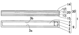
この発明に係る液晶表示装置(1)の一実施形態を図1に示す。この液晶表示装置(1)は、面光源装置(9)と、該面光源装置(9)の前面側に配置された液晶パネル(30)とを備えている。 One embodiment of a liquid crystal display device (1) according to the present invention is shown in FIG. The liquid crystal display device (1) includes a surface light source device (9) and a liquid crystal panel (30) disposed on the front side of the surface light source device (9).
前記液晶パネル(30)は、相互に離間して平行状に配置された上下一対の透明電極(12)(13)の間に液晶(11)が封入されてなる液晶セル(20)と、該液晶セル(20)の上下両側に配置された偏光板(14)(15)とを備えてなる。これら構成部材(11)(12)(13)(14)(15)によって画像表示部が構成されている。なお、前記透明電極(12)(13)の内面(液晶側の面)にはそれぞれ配向膜(図示しない)が積層されている。 The liquid crystal panel (30) includes a liquid crystal cell (20) in which a liquid crystal (11) is sealed between a pair of upper and lower transparent electrodes (12) and (13) arranged in parallel and spaced apart from each other. The liquid crystal cell (20) includes polarizing plates (14) and (15) disposed on both upper and lower sides. These constituent members (11), (12), (13), (14), and (15) constitute an image display unit. An alignment film (not shown) is laminated on the inner surfaces (surfaces on the liquid crystal side) of the transparent electrodes (12) and (13).
前記面光源装置(9)は、前記下側の偏光板(15)の下面側(背面側)に配置されている。この面光源装置(9)は、平面視矩形状で上面側(前面側)が開放された薄箱型形状のランプボックス(5)と、該ランプボックス(5)内に収容された導光板(3)及び光源(2)と、前記ランプボックス(5)に対してその開放面を塞ぐように載置されて固定された光拡散板(4)とを備えている。前記光源(2)は、前記導光板(3)の側方位置に配置されている、即ち導光板(3)の一側面に対して接触状態に配置されている。前記ランプボックス(5)は、白色のアクリル系樹脂板で製作されている。前記導光板(3)の背面(3a)には白色インクによるドット印刷部(ドットパターン)が形成されていて、前記光源(2)から導光板(3)内にその一側面から入射した光を該ドット印刷部により反射させることによって、導光板の前面、即ち光出射面(3b)から光を均一に出射できるものとなされている。 The surface light source device (9) is disposed on the lower surface side (rear surface side) of the lower polarizing plate (15). The surface light source device (9) includes a thin box-shaped lamp box (5) having a rectangular shape in plan view and an open upper surface (front surface), and a light guide plate (5) accommodated in the lamp box (5). 3) and a light source (2), and a light diffusing plate (4) mounted and fixed to the lamp box (5) so as to close its open surface. The said light source (2) is arrange | positioned in the side position of the said light-guide plate (3), ie, is arrange | positioned in the contact state with respect to one side surface of the light-guide plate (3). The lamp box (5) is made of a white acrylic resin plate. On the back surface (3a) of the light guide plate (3), a dot printing portion (dot pattern) made of white ink is formed, and light incident from one side surface into the light guide plate (3) from the light source (2) is received. The light is uniformly emitted from the front surface of the light guide plate, that is, the light emitting surface (3b), by being reflected by the dot printing unit.
前記導光板(3)は、透明樹脂中に微粒子が分散されてなる樹脂組成物の板状体からなる。 The said light-guide plate (3) consists of a plate-shaped body of the resin composition by which microparticles | fine-particles are disperse | distributed in transparent resin.
前記導光板(3)は、次のような関係式が成立するように構成されている。即ち、前記透明樹脂の屈折率と前記微粒子の屈折率の差の絶対値を「Δn」とし、前記微粒子の累積50%粒子径を「D50」(μm)としたとき、0.30≦Δn×D50≦0.70の関係式が成立する。即ち、このような関係式を満足する透明樹脂および微粒子により前記導光板(3)が構成されている。 The light guide plate (3) is configured to satisfy the following relational expression. That is, when the absolute value of the difference between the refractive index of the transparent resin and the refractive index of the fine particles is “Δn” and the cumulative 50% particle diameter of the fine particles is “D 50 ” (μm), 0.30 ≦ Δn XD 50 ≦ 0.70 is established. That is, the light guide plate (3) is composed of transparent resin and fine particles that satisfy such a relational expression.
更に、前記導光板(3)は、300mmの光路長で測定された可視光の平均光線透過率が35%以上である。 Further, the light guide plate (3) has an average light transmittance of 35% or more measured with an optical path length of 300 mm.
上記構成に係る導光板(3)は、0.30≦Δn×D50≦0.70の関係式が成立する構成であり、このような関係式を満足する微粒子は、可視光のどの波長の光も同程度に散乱させることができるので、導光板(3)の光出射面(3b)から出射される光の黄色味が十分に低減され、実質的に黄色味を帯びていない白色度の高い光を出射できる。また、300mmの光路長で測定された可視光の平均光線透過率が35%以上であるから、高輝度光を出射することができる。 The light guide plate (3) according to the above configuration has a configuration in which the relational expression of 0.30 ≦ Δn × D 50 ≦ 0.70 is established, and the fine particles satisfying such a relational expression have any wavelength of visible light. Since the light can be scattered to the same extent, the yellowness of the light emitted from the light emitting surface (3b) of the light guide plate (3) is sufficiently reduced, and the whiteness that is not substantially yellowish is obtained. High light can be emitted. Moreover, since the average light transmittance of visible light measured with the optical path length of 300 mm is 35% or more, high-intensity light can be emitted.
従って、前記液晶表示装置(1)では、面光源装置(9)から実質的に黄色味を帯びていない白色度の高い光が高輝度で液晶パネル(30)に向けて出射されるから、液晶パネル(30)の色を正確に再現することができて、黄色味を帯びることなく自然で高品位な明るいカラー表示を実現できる。 Accordingly, in the liquid crystal display device (1), light having a high whiteness that is not substantially yellowish is emitted from the surface light source device (9) toward the liquid crystal panel (30) with high brightness. The color of the panel (30) can be accurately reproduced, and a natural and high-quality bright color display can be realized without being yellowish.
なお、Δn×D50<0.30または0.70<Δn×D50の関係式が成立する場合には、出射光が黄色味を帯びてしまい、面光源装置(9)から白色度の高い拡散光を出射させることができない。従って、この場合には自然で高品位なカラー表示を実現できる液晶表示装置を構成することはできない。 In addition, when the relational expression Δn × D 50 <0.30 or 0.70 <Δn × D 50 is satisfied, the emitted light is tinged with yellow and the whiteness level is high from the surface light source device (9). Diffuse light cannot be emitted. Therefore, in this case, a liquid crystal display device capable of realizing a natural and high-quality color display cannot be configured.
中でも、0.35≦Δn×D50≦0.65の関係式が成立する構成であるのが、より白色度の高い光を出射できる点で、好ましい。 Among them, the configuration in which the relational expression of 0.35 ≦ Δn × D 50 ≦ 0.65 is satisfied is preferable in that light with higher whiteness can be emitted.
前記導光板(3)としては、透明樹脂中に微粒子が分散されてなる樹脂組成物の板状体であれば特に限定されずどのようなものでも使用できる。 The light guide plate (3) is not particularly limited as long as it is a plate-shaped body of a resin composition in which fine particles are dispersed in a transparent resin. Any light guide plate can be used.
前記透明樹脂としては、例えばメタクリル樹脂(PMMA等)、ポリカーボネート樹脂、ABS樹脂(アクリロニトリル−スチレン−ブタジエン共重合体樹脂)、MS樹脂(メタクリル酸メチル−スチレン共重合体樹脂)、ポリスチレン樹脂、AS樹脂(アクリロニトリル−スチレン共重合体樹脂)、ポリオレフィン樹脂(ポリエチレン、ポリプロピレン等)などが挙げられる。 Examples of the transparent resin include methacrylic resin (PMMA, etc.), polycarbonate resin, ABS resin (acrylonitrile-styrene-butadiene copolymer resin), MS resin (methyl methacrylate-styrene copolymer resin), polystyrene resin, AS resin. (Acrylonitrile-styrene copolymer resin), polyolefin resin (polyethylene, polypropylene, etc.) and the like.
前記微粒子としては、前記導光板(3)を構成する透明樹脂と屈折率が相違する微粒子であって透過光を拡散し得るものであれば特に限定されずどのようなものでも使用できる。例えば、ガラスビーズ、シリカ粒子、水酸化アルミニウム粒子、炭酸カルシウム粒子、硫酸バリウム粒子、酸化チタン粒子、タルク等の無機粒子や、スチレン系重合体粒子、アクリル系重合体粒子、シロキサン系重合体粒子等の樹脂粒子などが挙げられる。 The fine particles are not particularly limited as long as they are fine particles having a refractive index different from that of the transparent resin constituting the light guide plate (3) and can diffuse transmitted light. For example, inorganic particles such as glass beads, silica particles, aluminum hydroxide particles, calcium carbonate particles, barium sulfate particles, titanium oxide particles, talc, styrene polymer particles, acrylic polymer particles, siloxane polymer particles, etc. Resin particles and the like.
前記微粒子の累積50%粒子径(D50)は、3〜7μmの範囲であるのが好ましい。3μm以上であることで透過光を十分に散乱させることができると共に7μm以下であることで導光板(3)の光出射面(3b)等の表面をより平滑にすることができる。 The cumulative 50% particle diameter (D 50 ) of the fine particles is preferably in the range of 3 to 7 μm. When it is 3 μm or more, the transmitted light can be sufficiently scattered, and when it is 7 μm or less, the surface of the light guide plate (3) such as the light exit surface (3b) can be made smoother.
前記透明樹脂の屈折率と前記微粒子の屈折率の差の絶対値Δnは、0.08〜0.13に設定されるのが好ましい。屈折率の差の絶対値Δnがこのような範囲であれば、所望の光散乱を得るために要する微粒子の含有量は少なくて済み、このような微粒子含有量の低減によって、加工性を向上できる利点がある。 The absolute value Δn of the difference between the refractive index of the transparent resin and the refractive index of the fine particles is preferably set to 0.08 to 0.13. If the absolute value Δn of the difference in refractive index is within such a range, the content of fine particles required to obtain desired light scattering is small, and the workability can be improved by reducing the fine particle content. There are advantages.
前記導光板(3)における前記微粒子の含有率は0.2〜20ppmに設定されるのが好ましい。0.2ppm以上とすることで透過光を十分に散乱させることができると共に20ppm以下であることで微粒子の凝集等による微粒子の偏在を低減できる。中でも、前記導光板(3)における微粒子の含有率は0.5〜10ppmに設定されるのがより好ましい。 The content of the fine particles in the light guide plate (3) is preferably set to 0.2 to 20 ppm. By setting the concentration to 0.2 ppm or more, the transmitted light can be sufficiently scattered, and by setting the concentration to 20 ppm or less, uneven distribution of fine particles due to aggregation of the fine particles can be reduced. Especially, it is more preferable that the content rate of the microparticles | fine-particles in the said light-guide plate (3) is set to 0.5-10 ppm.
前記導光板(3)には、例えば紫外線吸収剤、熱安定剤、酸化防止剤、耐候剤、光安定剤、蛍光増白剤、加工安定剤等の各種添加剤を添加含有せしめても良い。また、この発明の効果を阻害しない範囲であれば、前記特定の関係式を満足する微粒子以外の他の微粒子を添加することもできる。 The light guide plate (3) may contain various additives such as an ultraviolet absorber, a heat stabilizer, an antioxidant, a weathering agent, a light stabilizer, a fluorescent brightening agent, and a processing stabilizer. Further, fine particles other than the fine particles satisfying the specific relational expression can be added as long as the effects of the present invention are not impaired.
前記導光板(3)の厚さは、特に限定されないが、通常は0.05〜15mmであり、好ましくは0.1〜10mmであり、より好ましくは0.5〜5mmである。 Although the thickness of the said light-guide plate (3) is not specifically limited, Usually, it is 0.05-15 mm, Preferably it is 0.1-10 mm, More preferably, it is 0.5-5 mm.
本発明では、前記導光板(3)が、300mmの光路長で測定された可視光の平均光線透過率が35%以上であることによって、高輝度化を図ることができるのであるが、中でも、前記導光板(3)は、300mmの光路長で測定された可視光の平均光線透過率が50%以上であるのが好ましく、特に好ましいのは60%以上である。 In the present invention, since the light guide plate (3) has an average light transmittance of visible light measured at an optical path length of 300 mm of 35% or more, high brightness can be achieved. The light guide plate (3) preferably has an average visible light transmittance of 50% or more measured at an optical path length of 300 mm, particularly preferably 60% or more.
前記導光板(3)の製造方法としては、樹脂板の成形方法として公知の成形法を用いることができ、特に限定されないが、例えば熱プレス法、溶融押出法、射出成形法等が挙げられる。 As a manufacturing method of the said light-guide plate (3), a well-known shaping | molding method can be used as a shaping | molding method of a resin plate, Although it does not specifically limit, For example, a hot press method, a melt extrusion method, an injection molding method etc. are mentioned.
この発明において、前記導光板(3)は、次のような処理加工が施されていても良い。即ち、例えば、周側面(51)が研磨処理されていても良いし、光出射面(3b)に均一光にするための光拡散処理が施されていても良いし、背面(3a)に白色インク等を用いたドット印刷、プリズムの形成等の光拡散処理が施されていても良いし、或いは導光板の光出射面(3b)以外の面に、銀蒸着されたシートやフィルム等の光反射層が設けられていても良い。 In the present invention, the light guide plate (3) may be subjected to the following processing. That is, for example, the peripheral side surface (51) may be polished, the light emitting surface (3b) may be subjected to light diffusion processing to make uniform light, and the back surface (3a) may be white. Light diffusion processing such as dot printing using ink or the like, formation of a prism, or the like, or light such as a silver-deposited sheet or film on a surface other than the light exit surface (3b) of the light guide plate A reflective layer may be provided.
上記実施形態(図1)では、導光板(3)の4つの側面(51)のうち一側面側に光源(2)が配置された構成が採用されていたが、特にこのような構成に限定されるものではなく、例えば、導光板(3)における対向する一対の側面にそれぞれ光源(2)が配置された構成を採用しても良い。 In the said embodiment (FIG. 1), the structure by which the light source (2) was arrange | positioned in one side surface among the four side surfaces (51) of a light-guide plate (3) was employ | adopted, but it is limited especially in such a structure. For example, a configuration in which the light source (2) is disposed on each of a pair of opposing side surfaces of the light guide plate (3) may be employed.
なお、前記光源(2)としては、特に限定されるものではないが、例えば冷陰極管、熱陰極管、EEFL(外部電極蛍光ランプ)等の線状光源の他、発光ダイオード(LED)等の点状光源などが用いられる。 The light source (2) is not particularly limited. For example, in addition to a linear light source such as a cold cathode tube, a hot cathode tube, or an EEFL (external electrode fluorescent lamp), a light emitting diode (LED) or the like is used. A point light source or the like is used.
この発明に係る導光板(3)、面光源装置(9)及び液晶表示装置(1)は、上記実施形態のものに特に限定されるものではなく、請求の範囲内であれば、その精神を逸脱するものでない限りいかなる設計的変更をも許容するものである。 The light guide plate (3), the surface light source device (9) and the liquid crystal display device (1) according to the present invention are not particularly limited to those of the above-described embodiment, and the spirit thereof is within the scope of the claims. Any design changes are allowed as long as they do not deviate.
次に、この発明の具体的実施例について説明するが、本発明はこれら実施例のものに特に限定されるものではない。 Next, specific examples of the present invention will be described, but the present invention is not particularly limited to these examples.
<実施例1>
PMMA(ポリメチルメタアクリレート)(住友化学株式会社製「スミペックスEXN」、屈折率:1.49)に、ポリスチレン樹脂微粒子(積水化成品工業株式会社製「SBX−4」、屈折率:1.59)をその含有率が0.5ppmとなるように混ぜてヘンシェルミキサーで混合した後、スクリュー径40mmの1軸押出機で溶融混練して樹脂温度265℃でTダイから押出すことによって、厚さ4mm、幅20cmの導光板を製作した。なお、前記ポリスチレン樹脂微粒子の累積50%粒子径(D50)は3.7(μm)であった。
<Example 1>
PMMA (polymethyl methacrylate) (“SUMIPEX EXN” manufactured by Sumitomo Chemical Co., Ltd., refractive index: 1.49) and polystyrene resin fine particles (“SBX-4” manufactured by Sekisui Plastics Co., Ltd.), refractive index: 1.59 ) Is mixed with a Henschel mixer so that the content is 0.5 ppm, melt-kneaded with a single screw extruder with a screw diameter of 40 mm, and extruded from a T die at a resin temperature of 265 ° C. A light guide plate of 4 mm and a width of 20 cm was produced. The cumulative 50% particle diameter (D 50 ) of the polystyrene resin fine particles was 3.7 (μm).
<実施例2>
ポリスチレン樹脂微粒子の含有率を1ppmに設定した以外は、実施例1と同様にして導光板を製作した。
<Example 2>
A light guide plate was produced in the same manner as in Example 1 except that the content of the polystyrene resin fine particles was set to 1 ppm.
<実施例3>
ポリスチレン樹脂微粒子の含有率を3ppmに設定した以外は、実施例1と同様にして導光板を製作した。
<Example 3>
A light guide plate was produced in the same manner as in Example 1 except that the content of the polystyrene resin fine particles was set to 3 ppm.
<実施例4>
ポリスチレン樹脂微粒子の含有率を10ppmに設定した以外は、実施例1と同様にして導光板を製作した。
<Example 4>
A light guide plate was produced in the same manner as in Example 1 except that the content of the polystyrene resin fine particles was set to 10 ppm.
<実施例5>
PMMA(ポリメチルメタアクリレート)(住友化学株式会社製「スミペックスEXN」、屈折率:1.49)に、ポリスチレン樹脂微粒子(積水化成品工業株式会社製「SBX−6」、屈折率:1.59)をその含有率が0.5ppmとなるように混ぜてヘンシェルミキサーで混合した後、スクリュー径40mmの1軸押出機で溶融混練して樹脂温度265℃でTダイから押出すことによって、厚さ4mm、幅20cmの導光板を製作した。なお、前記ポリスチレン樹脂微粒子の累積50%粒子径(D50)は5.8(μm)であった。
<Example 5>
PMMA (polymethyl methacrylate) (“SUMIPEX EXN” manufactured by Sumitomo Chemical Co., Ltd., refractive index: 1.49) and polystyrene resin fine particles (“SBX-6” manufactured by Sekisui Plastics Co., Ltd.), refractive index: 1.59 ) Is mixed with a Henschel mixer so that the content is 0.5 ppm, melt-kneaded with a single screw extruder with a screw diameter of 40 mm, and extruded from a T die at a resin temperature of 265 ° C. A light guide plate of 4 mm and a width of 20 cm was produced. The cumulative 50% particle diameter (D 50 ) of the polystyrene resin fine particles was 5.8 (μm).
<実施例6>
ポリスチレン樹脂微粒子の含有率を1ppmに設定した以外は、実施例5と同様にして導光板を製作した。
<Example 6>
A light guide plate was produced in the same manner as in Example 5 except that the content of the polystyrene resin fine particles was set to 1 ppm.
<実施例7>
ポリスチレン樹脂微粒子の含有率を5ppmに設定した以外は、実施例5と同様にして導光板を製作した。
<Example 7>
A light guide plate was produced in the same manner as in Example 5 except that the content of the polystyrene resin fine particles was set to 5 ppm.
<比較例1>
ポリスチレン樹脂微粒子の含有率を21ppmに設定した以外は、実施例5と同様にして導光板を製作した。
<Comparative Example 1>
A light guide plate was produced in the same manner as in Example 5 except that the content of the polystyrene resin fine particles was set to 21 ppm.
<比較例2>
PMMA(ポリメチルメタアクリレート)(住友化学株式会社製「スミペックスEXN」、屈折率:1.49)に、ポリスチレン樹脂微粒子(積水化成品工業株式会社製「XX52K」、屈折率:1.59)をその含有率が0.5ppmとなるように混ぜてヘンシェルミキサーで混合した後、スクリュー径40mmの1軸押出機で溶融混練して樹脂温度265℃でTダイから押出すことによって、厚さ4mm、幅20cmの導光板を製作した。なお、前記ポリスチレン樹脂微粒子の累積50%粒子径(D50)は2.8(μm)であった。
<Comparative example 2>
Polystyrene resin fine particles (“XX52K” manufactured by Sekisui Plastics Co., Ltd., refractive index: 1.59) are added to PMMA (polymethyl methacrylate) (“SUMIPEX EXN” manufactured by Sumitomo Chemical Co., Ltd., refractive index: 1.49). After mixing with a Henschel mixer so that the content is 0.5 ppm, melt kneading with a single screw extruder with a screw diameter of 40 mm and extruding from a T die at a resin temperature of 265 ° C., a thickness of 4 mm, A light guide plate with a width of 20 cm was produced. The cumulative 50% particle diameter (D 50 ) of the polystyrene resin fine particles was 2.8 (μm).
<比較例3>
ポリスチレン樹脂微粒子の含有率を1ppmに設定した以外は、比較例2と同様にして導光板を製作した。
<Comparative Example 3>
A light guide plate was produced in the same manner as in Comparative Example 2 except that the content of the polystyrene resin fine particles was set to 1 ppm.
<比較例4>
ポリスチレン樹脂微粒子の含有率を3ppmに設定した以外は、比較例2と同様にして導光板を製作した。
<Comparative example 4>
A light guide plate was produced in the same manner as in Comparative Example 2 except that the content of the polystyrene resin fine particles was set to 3 ppm.
<比較例5>
ポリスチレン樹脂微粒子の含有率を10ppmに設定した以外は、比較例2と同様にして導光板を製作した。
<Comparative Example 5>
A light guide plate was produced in the same manner as in Comparative Example 2 except that the content of the polystyrene resin fine particles was set to 10 ppm.
<比較例6>
PMMA(ポリメチルメタアクリレート)(住友化学株式会社製「スミペックスEXN」、屈折率:1.49)に、ポリスチレン樹脂微粒子(積水化成品工業株式会社製「SBX−8」、屈折率:1.59)をその含有率が0.5ppmとなるように混ぜてヘンシェルミキサーで混合した後、スクリュー径40mmの1軸押出機で溶融混練して樹脂温度265℃でTダイから押出すことによって、厚さ4mm、幅20cmの導光板を製作した。なお、前記ポリスチレン樹脂微粒子の累積50%粒子径(D50)は7.9(μm)であった。
<Comparative Example 6>
PMMA (polymethyl methacrylate) (“SUMIPEX EXN” manufactured by Sumitomo Chemical Co., Ltd., refractive index: 1.49) and polystyrene resin fine particles (“SBX-8” manufactured by Sekisui Plastics Co., Ltd.), refractive index: 1.59 ) Is mixed with a Henschel mixer so that the content is 0.5 ppm, melt-kneaded with a single screw extruder with a screw diameter of 40 mm, and extruded from a T die at a resin temperature of 265 ° C. A light guide plate of 4 mm and a width of 20 cm was produced. The cumulative 50% particle diameter (D 50 ) of the polystyrene resin fine particles was 7.9 (μm).
<比較例7>
ポリスチレン樹脂微粒子の含有率を10ppmに設定した以外は、比較例6と同様にして導光板を製作した。
<Comparative Example 7>
A light guide plate was produced in the same manner as in Comparative Example 6 except that the content of the polystyrene resin fine particles was set to 10 ppm.
<比較例8>
PMMA(ポリメチルメタアクリレート)(住友化学株式会社製「スミペックスEXN」、屈折率:1.49)に、アクリル樹脂微粒子(株式会社日本触媒製「エポスターMA1002」、屈折率:1.492)をその含有率が1000ppmとなるように混ぜてヘンシェルミキサーで混合した後、スクリュー径40mmの1軸押出機で溶融混練して樹脂温度265℃でTダイから押出すことによって、厚さ4mm、幅20cmの導光板を製作した。なお、前記アクリル樹脂微粒子の累積50%粒子径(D50)は2.0(μm)であった。
<Comparative Example 8>
PMMA (polymethyl methacrylate) (“SUMIPEX EXN” manufactured by Sumitomo Chemical Co., Ltd., refractive index: 1.49) and acrylic resin fine particles (“Epaster MA1002” manufactured by Nippon Shokubai Co., Ltd., refractive index: 1.492) After mixing with a Henschel mixer so that the content rate becomes 1000 ppm, the mixture is melt-kneaded with a single screw extruder with a screw diameter of 40 mm and extruded from a T die at a resin temperature of 265 ° C., thereby having a thickness of 4 mm and a width of 20 cm. A light guide plate was produced. The 50% cumulative particle diameter (D 50 ) of the acrylic resin fine particles was 2.0 (μm).
<微粒子の累積50%粒子径の測定方法>
微粒子の累積50%粒子径(D50)は、日機装株式会社製マイクロトラック粒度分析計(モデル9220FRA)を用いてレーザー光源前方散乱光のフラウンホーファ回折法により測定した。測定に際しては、0.1g程度の微粒子をメタノール中に分散させて分散液を得、この分散液に超音波を5分間照射した後、該分散液を前記マイクロトラック粒度分析計のサンプル投入口に投入して測定を行った。なお、累積50%粒子径(D50)は、全粒子の粒子径及び体積を測定し、小さい粒子径のものから順次体積を積算し、該積算体積が全粒子の合計体積に対して50%となる粒子の粒子径である。
<Measurement method of 50% cumulative particle size of fine particles>
The cumulative 50% particle size (D 50 ) of the fine particles was measured by the Fraunhofer diffraction method of the laser light source forward scattered light using a Nikkiso Co., Ltd. Microtrac particle size analyzer (model 9220FRA). In the measurement, about 0.1 g of fine particles are dispersed in methanol to obtain a dispersion, and the dispersion is irradiated with ultrasonic waves for 5 minutes, and then the dispersion is introduced into the sample inlet of the microtrack particle size analyzer. The measurement was carried out. The cumulative 50% particle diameter (D 50 ) is determined by measuring the particle diameter and volume of all particles, and integrating the volume sequentially from the smallest particle diameter, and the accumulated volume is 50% of the total volume of all particles. The particle diameter of the particles to be
上記のようにして得られた各導光板について下記評価法に従い評価を行った。その結果を表1、2に示す。 Each light guide plate obtained as described above was evaluated according to the following evaluation method. The results are shown in Tables 1 and 2.
<光路長300mmでの可視光の平均光線透過率の測定法>
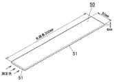
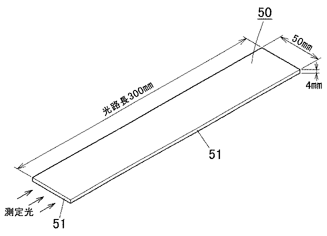
図2に示すように、得られた導光板を幅50mm×長さ300mmの大きさに切断した後、4つの側面(51)を研磨機(朝日メガロ社製「プラビューティー1000」)で研磨して測定試験片(50)を作製した。この測定試験片を日立製作所製プラスチック特性測定システム(U−3410型分光光度計及び大型試料室積分球付属装置で構成される)で300mmの光路長で波長380〜780nmの範囲で5nm刻みで各波長毎の光線透過率を測定し、このようにして得られた光線透過率の算術平均値を「可視光の平均光線透過率」とした。
<Measurement method of average light transmittance of visible light at optical path length of 300 mm>
As shown in FIG. 2, the obtained light guide plate was cut into a size of 50 mm in width and 300 mm in length, and then the four side surfaces (51) were polished with a polishing machine (“Pura Beauty 1000” manufactured by Asahi Megaro). A test specimen (50) was prepared. Each of these measurement specimens was measured in increments of 5 nm in a wavelength range of 380 to 780 nm with an optical path length of 300 mm using a plastic property measurement system manufactured by Hitachi, Ltd. (consisting of a U-3410 type spectrophotometer and a large sample chamber integrating sphere accessory) The light transmittance for each wavelength was measured, and the arithmetic average value of the light transmittance thus obtained was defined as “average light transmittance of visible light”.
<YI(イエローインデックス)の評価法>
図2に示すように、得られた導光板を幅50mm×長さ300mmの大きさに切断した後、4つの側面(51)を研磨機(朝日メガロ社製「プラビューティー1000」)で研磨して測定試験片(50)を作製した。この測定試験片を日立製作所製プラスチック特性測定システム(U−3410型分光光度計及び大型試料室積分球付属装置で構成される)で300mmの光路長で波長380〜780nmの範囲で5nm刻みで各波長毎の光線透過率を測定し、これよりYI(イエローインデックス)を算出した。なお、YIが2.0以下であるものを合格とした。
<YI (Yellow Index) Evaluation Method>
As shown in FIG. 2, the obtained light guide plate was cut into a size of 50 mm in width and 300 mm in length, and then the four side surfaces (51) were polished with a polishing machine (“Pura Beauty 1000” manufactured by Asahi Megaro). A test specimen (50) was prepared. Each of these measurement specimens was measured in increments of 5 nm in a wavelength range of 380 to 780 nm with an optical path length of 300 mm using a plastic property measurement system manufactured by Hitachi, Ltd. (consisting of a U-3410 type spectrophotometer and a large sample chamber integrating sphere accessory) The light transmittance for each wavelength was measured, and YI (yellow index) was calculated from this. In addition, the thing whose YI is 2.0 or less was set as the pass.
表1から明らかなように、この発明の実施例1〜7の導光板は、YIが十分に低減されているので、実質的に黄色味を帯びていない白色度の高い光を出射できる。また、300mmの光路長で測定された可視光の平均光線透過率が35%以上であるから、十分な輝度を確保できる。 As is apparent from Table 1, the light guide plates of Examples 1 to 7 of the present invention have a sufficiently reduced YI, and thus can emit light with high whiteness that is not substantially yellowish. Moreover, since the average light transmittance of visible light measured with the optical path length of 300 mm is 35% or more, sufficient luminance can be ensured.
これに対し、この発明の規定範囲を逸脱する比較例1〜8の導光板では、YIが大きい値であった。 On the other hand, YI was a large value in the light guide plates of Comparative Examples 1 to 8 that deviated from the specified range of the present invention.
なお、実施例1、5と比較例2、6の対比から、(Δn×D50)が0.30より小さい場合にはYIが大きくなり、(Δn×D50)が0.70より大きい場合にはYIが大きくなるのに対し、(Δn×D50)が0.30〜0.70の範囲であればYIが十分に小さくなることがわかる。 From the comparison between Examples 1 and 5 and Comparative Examples 2 and 6, when (Δn × D 50 ) is smaller than 0.30, YI increases, and (Δn × D 50 ) is larger than 0.70. It can be seen that YI becomes large while YI is sufficiently small when (Δn × D 50 ) is in the range of 0.30 to 0.70.
また、実施例2、6と比較例3の対比から、(Δn×D50)が0.30より小さい場合にはYIが大きくなるのに対し、(Δn×D50)が0.30〜0.70の範囲であればYIが十分に小さくなることがわかる。 From the comparison between Examples 2 and 6 and Comparative Example 3, YI increases when (Δn × D 50 ) is smaller than 0.30, whereas (Δn × D 50 ) is 0.30 to 0. It can be seen that YI is sufficiently small in the range of .70.
また、実施例3と比較例4の対比から、(Δn×D50)が0.30より小さい場合にはYIが大きくなるのに対し、(Δn×D50)が0.30〜0.70の範囲であればYIが十分に小さくなることがわかる。 From the comparison between Example 3 and Comparative Example 4, YI increases when (Δn × D 50 ) is smaller than 0.30, whereas (Δn × D 50 ) is 0.30 to 0.70. In this range, it can be seen that YI is sufficiently small.
また、実施例4と比較例5、7の対比から、(Δn×D50)が0.30より小さい場合にはYIが大きくなり、(Δn×D50)が0.70より大きい場合にはYIが大きくなるのに対し、(Δn×D50)が0.30〜0.70の範囲であればYIが十分に小さくなることがわかる。 Further, from the comparison between Example 4 and Comparative Examples 5 and 7, when (Δn × D 50 ) is smaller than 0.30, YI increases, and when (Δn × D 50 ) is larger than 0.70. It can be seen that while YI increases, YI decreases sufficiently when (Δn × D 50 ) is in the range of 0.30 to 0.70.
また、実施例5〜7と比較例1の対比から、導光板中の微粒子の含有率が20ppmを超えると、300mmの光路長で測定された可視光の平均光線透過率が35%より小さくなる上に、YIも大きくなることがわかる。 Further, from the comparison between Examples 5 to 7 and Comparative Example 1, when the content ratio of the fine particles in the light guide plate exceeds 20 ppm, the average light transmittance of visible light measured at an optical path length of 300 mm is smaller than 35%. It can also be seen that YI also increases.
また、実施例6と比較例8の対比から、平均光線透過率がほぼ同等であっても、(Δn×D50)が0.30より小さい場合にはYIが大きくなるのに対し、(Δn×D50)が0.30〜0.70の範囲であればYIが十分に小さくなることがわかる。 Further, from the comparison between Example 6 and Comparative Example 8, even when the average light transmittance is substantially equal, YI increases when (Δn × D 50 ) is smaller than 0.30, whereas (Δn × D 50) it can be seen that the YI is sufficiently small as long as the range of 0.30 to 0.70.
この発明に係る導光板は、面光源装置用の導光板として好適に用いられるが、特にこのような用途に限定されるものではない。また、この発明の面光源装置は、液晶表示装置用のバックライトとして好適に用いられるが、特にこのような用途に限定されるものではなく、例えばその他の表示装置用、照明装置用、看板用等として用いられる。 The light guide plate according to the present invention is suitably used as a light guide plate for a surface light source device, but is not particularly limited to such applications. Further, the surface light source device of the present invention is suitably used as a backlight for a liquid crystal display device, but is not particularly limited to such applications, for example, for other display devices, lighting devices, signboards. Etc.
1…液晶表示装置
2…光源
3…導光板
9…面光源装置
30…液晶パネル
DESCRIPTION OF
Claims (7)
前記透明樹脂の屈折率と前記微粒子の屈折率の差の絶対値を「Δn」とし、前記微粒子の累積50%粒子径を「D50」(μm)としたとき、0.30≦Δn×D50≦0.70の関係式が成立し、
300mmの光路長で測定された可視光の平均光線透過率が35%以上であることを特徴とする導光板。 A light guide plate in which fine particles are dispersed in a transparent resin,
When the absolute value of the difference between the refractive index of the transparent resin and the refractive index of the fine particles is “Δn” and the cumulative 50% particle diameter of the fine particles is “D 50 ” (μm), 0.30 ≦ Δn × D The relational expression 50 ≦ 0.70 holds,
A light guide plate, wherein an average light transmittance of visible light measured at an optical path length of 300 mm is 35% or more.
Priority Applications (5)
| Application Number | Priority Date | Filing Date | Title |
|---|---|---|---|
| JP2008262687A JP4933512B2 (en) | 2008-10-09 | 2008-10-09 | Light guide plate |
| PCT/JP2009/067945 WO2010041768A1 (en) | 2008-10-09 | 2009-10-08 | Light guide plate |
| KR1020117010433A KR20110070999A (en) | 2008-10-09 | 2009-10-08 | Light guide plate |
| CN200980139166.9A CN102171506B (en) | 2008-10-09 | 2009-10-08 | Light guide plate |
| TW98134137A TWI434080B (en) | 2008-10-09 | 2009-10-08 | A light guide plate, a surface light source device, and a liquid crystal display device |
Applications Claiming Priority (1)
| Application Number | Priority Date | Filing Date | Title |
|---|---|---|---|
| JP2008262687A JP4933512B2 (en) | 2008-10-09 | 2008-10-09 | Light guide plate |
Publications (2)
| Publication Number | Publication Date |
|---|---|
| JP2010092755A true JP2010092755A (en) | 2010-04-22 |
| JP4933512B2 JP4933512B2 (en) | 2012-05-16 |
Family
ID=42100710
Family Applications (1)
| Application Number | Title | Priority Date | Filing Date |
|---|---|---|---|
| JP2008262687A Expired - Fee Related JP4933512B2 (en) | 2008-10-09 | 2008-10-09 | Light guide plate |
Country Status (5)
| Country | Link |
|---|---|
| JP (1) | JP4933512B2 (en) |
| KR (1) | KR20110070999A (en) |
| CN (1) | CN102171506B (en) |
| TW (1) | TWI434080B (en) |
| WO (1) | WO2010041768A1 (en) |
Cited By (3)
| Publication number | Priority date | Publication date | Assignee | Title |
|---|---|---|---|---|
| JP2012018323A (en) * | 2010-07-08 | 2012-01-26 | Kuraray Co Ltd | Luminous body |
| WO2012111806A1 (en) * | 2011-02-18 | 2012-08-23 | 住友化学株式会社 | Inspection device and inspection method, and manufacture method using this inspection method |
| KR20120103464A (en) * | 2011-03-09 | 2012-09-19 | 스미또모 가가꾸 가부시끼가이샤 | A resin composition for a light guide plate and a light guide plate |
Families Citing this family (7)
| Publication number | Priority date | Publication date | Assignee | Title |
|---|---|---|---|---|
| GB2474120B (en) | 2009-10-01 | 2011-12-21 | Amira Pharmaceuticals Inc | Compounds as Lysophosphatidic acid receptor antagonists |
| GB2474748B (en) | 2009-10-01 | 2011-10-12 | Amira Pharmaceuticals Inc | Polycyclic compounds as lysophosphatidic acid receptor antagonists |
| CN102959313B (en) * | 2010-06-24 | 2015-07-08 | 东洋苯乙烯股份有限公司 | Light-guiding plate made of styrenic resin |
| JP5710295B2 (en) * | 2011-01-31 | 2015-04-30 | 住友化学株式会社 | UV curable inkjet ink for light guide plate and light guide plate using the same |
| TWI424220B (en) * | 2011-03-08 | 2014-01-21 | Tpv Display Technology Xiamen | Display structure |
| JP6666065B2 (en) | 2014-09-30 | 2020-03-13 | エルジー ディスプレイ カンパニー リミテッド | Liquid crystal display |
| CN104991304B (en) * | 2015-06-25 | 2019-02-22 | 东莞轩朗实业有限公司 | Light guide plate, ink and inkjet printing method for manufacturing light guide plate |
Citations (1)
| Publication number | Priority date | Publication date | Assignee | Title |
|---|---|---|---|---|
| JP2007048465A (en) * | 2005-08-05 | 2007-02-22 | Mitsubishi Rayon Co Ltd | Led surface light source device |
Family Cites Families (3)
| Publication number | Priority date | Publication date | Assignee | Title |
|---|---|---|---|---|
| JP2004327204A (en) * | 2003-04-24 | 2004-11-18 | Asahi Kasei Chemicals Corp | Optical diffusion layer integrated type light guide plate |
| TW200639522A (en) * | 2005-02-28 | 2006-11-16 | Kuraray Co | Light diffusion film, planar light source and liquid crystal display device utilizing the same |
| JP5063873B2 (en) * | 2005-07-05 | 2012-10-31 | 出光興産株式会社 | Light diffusing polycarbonate resin composition and light diffusing plate using the resin composition |
-
2008
- 2008-10-09 JP JP2008262687A patent/JP4933512B2/en not_active Expired - Fee Related
-
2009
- 2009-10-08 WO PCT/JP2009/067945 patent/WO2010041768A1/en active Application Filing
- 2009-10-08 TW TW98134137A patent/TWI434080B/en not_active IP Right Cessation
- 2009-10-08 CN CN200980139166.9A patent/CN102171506B/en not_active Expired - Fee Related
- 2009-10-08 KR KR1020117010433A patent/KR20110070999A/en not_active Application Discontinuation
Patent Citations (1)
| Publication number | Priority date | Publication date | Assignee | Title |
|---|---|---|---|---|
| JP2007048465A (en) * | 2005-08-05 | 2007-02-22 | Mitsubishi Rayon Co Ltd | Led surface light source device |
Cited By (3)
| Publication number | Priority date | Publication date | Assignee | Title |
|---|---|---|---|---|
| JP2012018323A (en) * | 2010-07-08 | 2012-01-26 | Kuraray Co Ltd | Luminous body |
| WO2012111806A1 (en) * | 2011-02-18 | 2012-08-23 | 住友化学株式会社 | Inspection device and inspection method, and manufacture method using this inspection method |
| KR20120103464A (en) * | 2011-03-09 | 2012-09-19 | 스미또모 가가꾸 가부시끼가이샤 | A resin composition for a light guide plate and a light guide plate |
Also Published As
| Publication number | Publication date |
|---|---|
| TWI434080B (en) | 2014-04-11 |
| CN102171506B (en) | 2015-03-04 |
| KR20110070999A (en) | 2011-06-27 |
| CN102171506A (en) | 2011-08-31 |
| JP4933512B2 (en) | 2012-05-16 |
| WO2010041768A1 (en) | 2010-04-15 |
| TW201033661A (en) | 2010-09-16 |
Similar Documents
| Publication | Publication Date | Title |
|---|---|---|
| JP4933512B2 (en) | Light guide plate | |
| KR100885608B1 (en) | Multi-layered light diffusion plate and liquid crystal display device comprising the same | |
| US6941056B2 (en) | Light guide and method for producing transparent thermoplastic resin composition for light guide | |
| CN101836037A (en) | Surface light source | |
| JP2007304553A (en) | Prism sheet, backlight unit having same, and liquid crystal display | |
| JP2008216879A (en) | White surface light source device and liquid crystal display device | |
| JP2005527842A (en) | Transparent thermoplastic composition comprising hollow glass spheres | |
| JP4976816B2 (en) | Liquid crystal display | |
| KR100994909B1 (en) | Multi-layered light diffusion plate having improved thermal resistance and liguid crystal display containing the same | |
| JP2008015442A (en) | Extruded polymer plate for anisotropic light scattering having high dimensional stability | |
| JPH04145485A (en) | Light source device | |
| JP2007298698A (en) | Light diffusing plate and planar irradiation apparatus | |
| JP2012188503A (en) | Resin composition for light guide plate, and light guide plate | |
| US20110285939A1 (en) | Liquid crystal display device | |
| JP2012145951A (en) | Liquid crystal display device | |
| WO2012002183A1 (en) | Liquid crystal display device and multilayer optical member | |
| JP2001195914A (en) | Lightguide plate for color monitor of acrylic resin series | |
| JP2012108547A (en) | Liquid crystal display device | |
| JP2001076522A (en) | Light source device | |
| JP2010140704A (en) | Light guide plate, and method of manufacturing light guide plate | |
| JP2012188504A (en) | Resin composition for light guide plate, and light guide plate | |
| JPH06324215A (en) | Light source device | |
| JP2009230963A (en) | Surface light source device and liquid crystal display device | |
| JP2009211810A (en) | Optical diffuser panel for downright backlight device and downright backlight device | |
| JP2011197354A (en) | Liquid crystal display device |
Legal Events
| Date | Code | Title | Description |
|---|---|---|---|
| A621 | Written request for application examination |
Free format text: JAPANESE INTERMEDIATE CODE: A621 Effective date: 20100208 |
|
| A131 | Notification of reasons for refusal |
Free format text: JAPANESE INTERMEDIATE CODE: A131 Effective date: 20111122 |
|
| TRDD | Decision of grant or rejection written | ||
| A01 | Written decision to grant a patent or to grant a registration (utility model) |
Free format text: JAPANESE INTERMEDIATE CODE: A01 Effective date: 20120208 |
|
| A01 | Written decision to grant a patent or to grant a registration (utility model) |
Free format text: JAPANESE INTERMEDIATE CODE: A01 |
|
| A61 | First payment of annual fees (during grant procedure) |
Free format text: JAPANESE INTERMEDIATE CODE: A61 Effective date: 20120216 |
|
| R150 | Certificate of patent or registration of utility model |
Ref document number: 4933512 Country of ref document: JP Free format text: JAPANESE INTERMEDIATE CODE: R150 Free format text: JAPANESE INTERMEDIATE CODE: R150 |
|
| FPAY | Renewal fee payment (event date is renewal date of database) |
Free format text: PAYMENT UNTIL: 20150224 Year of fee payment: 3 |
|
| LAPS | Cancellation because of no payment of annual fees |