JP2010092265A - Method for creating surface shape data and surface shape data creation device used for the same - Google Patents
Method for creating surface shape data and surface shape data creation device used for the same Download PDFInfo
- Publication number
- JP2010092265A JP2010092265A JP2008261585A JP2008261585A JP2010092265A JP 2010092265 A JP2010092265 A JP 2010092265A JP 2008261585 A JP2008261585 A JP 2008261585A JP 2008261585 A JP2008261585 A JP 2008261585A JP 2010092265 A JP2010092265 A JP 2010092265A
- Authority
- JP
- Japan
- Prior art keywords
- data
- surface shape
- height
- measurement data
- unit
- Prior art date
- Legal status (The legal status is an assumption and is not a legal conclusion. Google has not performed a legal analysis and makes no representation as to the accuracy of the status listed.)
- Granted
Links
Images
Abstract
Description
本発明は、例えば電気鋳造金型などの製作に用いられる表面形状データの作成技術に関する。 The present invention relates to a technique for creating surface shape data used for manufacturing, for example, an electroforming mold.
従来、例えば車両のインストルメントパネルや内装トリム材の表面に皮絞(皺)等の微細な形状を成形する場合、高品質なものが要求される際には、主として、電気鋳造金型が用いられている。
電気鋳造金型とは、電気めっきを応用して得られる金型であって、金属溶液の電気分解を利用してマスター型(マンドレル)の表面上に所定の厚さで金属を析出させ電着させた後、この電着層をマスター型から剥離することで得られるもの(ネガティブ型)で、マスター型とは全く逆の表面形状を有するものである。この電気鋳造金型を用いて成形することで、樹脂成形品にマスター型の表面形状を転写することが可能となる。またこの電気鋳造金型によれば、マスター型の表面上に金属を析出させることで、微細な表面形状を精度良く形成(転写)できるという利点がある。
Conventionally, for example, when molding a fine shape such as a skin squeeze (皺) on the surface of an instrument panel or interior trim material of a vehicle, when a high quality product is required, an electroforming mold is mainly used. It has been.
An electroforming mold is a mold obtained by applying electroplating. Electrodeposition is performed by depositing metal with a predetermined thickness on the surface of a master mold (mandrel) using electrolysis of a metal solution. Then, the electrodeposition layer is obtained by peeling the electrodeposition layer from the master mold (negative mold) and has a surface shape completely opposite to the master mold. By molding using this electroforming mold, the surface shape of the master mold can be transferred to the resin molded product. Moreover, according to this electrocasting die, there is an advantage that a fine surface shape can be formed (transferred) with high accuracy by depositing a metal on the surface of the master die.
上記マスター型を作製するため、例えば特開平7−241909号公報には、皮革モデルの表面形状を読み取った表面測定データを、画素位置を測定位置に対応させたグレースケール画像データに変換して、表面形状の深さ(測定位置における高さ位置)を濃度で表わすようにした技術が開示されている。濃度は例えば8ビット表示の場合256階調で表わすことができる。 In order to produce the master mold, for example, in Japanese Patent Laid-Open No. 7-241909, surface measurement data obtained by reading the surface shape of a leather model is converted into grayscale image data in which pixel positions correspond to measurement positions, A technique is disclosed in which the depth of the surface shape (the height position at the measurement position) is expressed by concentration. For example, the density can be expressed by 256 gradations in the case of 8-bit display.
画像データにおいてうねりや傷に対する欠陥処理を行い、あるいは繰り返しや強調などのデータ処理を行い、その処理後データに基づいた加工データにより、エッチングやレーザ彫刻等でマスター型を形成する。
車両内装材に一般的な皮絞模様では表面形状の深さ変化が0.3mm程度であるので、これを256階調に割り振ると1階調あたり1.17μmとなるが、このレベルでは滑らかに表現される。
特開2004−358662号公報にも、同様に表面測定データを画像データに変換し、これに基づいてマスター型を形成することが開示されている。
Since the change in depth of the surface shape is about 0.3 mm in a general leather pattern for vehicle interior materials, if this is assigned to 256 gradations, it becomes 1.17 μm per gradation, but at this level it is smooth Expressed.
Japanese Patent Application Laid-Open No. 2004-358862 also discloses that surface measurement data is converted into image data and a master mold is formed based on this.
ところで、近年の車両内装材では本革を縫い合わせたように見せるため、ステッチ(縫い目)部分の糸や周辺の持ち上がりまでも製品に表現されることが要求されるようになっている。
図5の(a)は右に皮絞模様Aとステッチ糸Bとが含まれる皮革モデルを模式的に示し、左に皮絞模様部分を拡大して示す。
ステッチ部分の糸の高さは例えば1mmに及ぶことがあり、これを含んで256階調で表現することになると、1階調あたり約3.9μmとなる。そうすると、本来微細な表現が要求される皮絞模様部分が、図5の(b)に示すA’のように、ギザギザの粗雑なものとなってしまう。
By the way, in recent vehicle interior materials, it seems that genuine leather is stitched together, and therefore, it is required to express even the thread at the stitch (seam) portion and the surrounding lifting in the product.
FIG. 5A schematically shows a leather model including a leather pattern A and stitch yarn B on the right, and an enlarged leather pattern part on the left.
The height of the thread at the stitch portion may reach, for example, 1 mm, and if it is expressed in 256 gradations including this, it will be about 3.9 μm per gradation. As a result, the squeezed pattern portion that is originally required to be finely expressed becomes jagged as shown by A ′ in FIG. 5B.
これに対処するためには8ビット表現のかわりに16ビット表現として階調数を大きくすることが考えられるが、この場合データ処理のための回路コストが増大するとともに、データ処理に時間がかかるという問題を招く。
そこで本発明は、限られた階調幅の画像データで、皮絞模様とステッチの糸など互いにかけ離れた高さをもつ表面形状でも、それぞれ微細な表現が確保されるマスター型を簡便に製作可能とする表面形状データ作成方法および装置を提供することを目的とする。
To deal with this, it is conceivable to increase the number of gradations as 16-bit representation instead of 8-bit representation, but in this case, the circuit cost for data processing increases and the data processing takes time. Cause problems.
Therefore, the present invention makes it possible to easily manufacture a master mold that can ensure fine expression even with surface shapes having a height apart from each other, such as a skin-drawn pattern and stitch threads, with image data of a limited gradation width. An object of the present invention is to provide a method and apparatus for creating surface shape data.
上記目的を達成するため、本発明は、モデルの表面測定データを所定の分割高さ単位でグループに分割し、分割したそれぞれのグループにおける表面測定データを、上記分割高さを順次に累積した値を基準値とするローカルデータに変換し、各グループのローカルデータを互いに異なる色チャンネルに割り当て、該色チャンネルを合成して多チャンネル色画像データに変換して表面形状データとするもので、上記所定の分割高さは、モデルの表面形状の高さを画像濃度で表わす際のあらかじめ定めた1階調当りの高さに所定の階調幅を乗じた値とするものとした。 In order to achieve the above object, the present invention divides the surface measurement data of the model into groups in a predetermined divided height unit, and the surface measurement data in each divided group is a value obtained by sequentially accumulating the divided heights. Is converted into local data with reference values, the local data of each group is assigned to different color channels, the color channels are combined and converted into multi-channel color image data to obtain surface shape data. The divided height is set to a value obtained by multiplying a predetermined height per gradation when the height of the surface shape of the model is represented by image density by a predetermined gradation width.
本発明によれば、1階調当りの高さをあらかじめ設定した値に抑えることができるので、微細で滑らかな模様等が表現される高精度の表面形状データが得られる。
そして、絞加工データ作成装置などに入力する場合に、多チャンネル色画像データは合成された1つのデータとして扱われるので、入力作業も一度で済み、取り扱いが簡便であるという効果を有する。
According to the present invention, since the height per gradation can be suppressed to a preset value, high-precision surface shape data expressing a fine and smooth pattern or the like can be obtained.
When inputting data to a drawing processing data creation device or the like, the multi-channel color image data is handled as a single piece of combined data, so that the input operation is only required once and the handling is simple.
次に本発明の実施の形態について説明する。
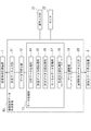
図1は実施の形態の構成を示すブロック図である。
表面形状データ作成装置10は、表面形状計測装置1からの表面測定データを入力する測定データ入力部11と、測定データ入力部11に入力された表面測定データを画像データに変換するデータ可視化部12と、画像データを素材として画像処理を行うデータ処理部13と、データのサイズを整えるデータ調整部19と、データ調整部で調整されたデータを表面形状データとして出力する表面形状データ出力部20とからなる。
表面形状データ作成装置10には、キーボードやジョグレバーなどからなる操作入力部21と、画像データが表示されるモニタ22とが接続される。
表面形状データは絞加工データ作成装置2に入力されて、ここでマスター型作製装置の使用に適した適宜のフォーマットに変換される。
Next, an embodiment of the present invention will be described.
FIG. 1 is a block diagram showing the configuration of the embodiment.
The surface shape data creation device 10 includes a measurement
The surface shape data creation apparatus 10 is connected to an
The surface shape data is input to the drawing processing
表面形状計測装置1は、皮革モデルの表面形状を計測し、3次元XYZ座標のデジタルデータに変換して表面測定データとするもので、光学式、レーザ式、あるいは触針式など適宜の計測装置を用いることができる。計測装置の計測可能面積によって、必要面積を1回で、あるいは分割して複数回で計測する。
The surface
データ可視化部12は、表面測定データのXY座標を画面の画素位置に割り当て、高さ位置を示すZ座標を濃度に割り当てた画像データを生成する。
データ可視化部12で可視化された画像データはモニタ21に表示される。操作者は操作入力部20を介してデータ処理部13を制御し、モニタ21上の画像データを修正することができる。
The
The image data visualized by the
データ処理部13は、欠陥データ処理部14、測定データ分割処理部15、形状データ合成処理部16、ローカルデータ変換部17および色成分合成処理部18を備えている。
欠陥データ処理部14は、操作入力部21の操作に基づいて、表面測定データの欠陥の修正を行うもので、微細な表面形状を測定し表面性状パラメータ等を算出する機能を備えた一般的なもので実現できる。
測定データ分割処理部15では、欠陥データ処理部14を経た表面測定データをその高さ方向で複数のデータ群に分割する。ここでは、あらかじめ設定してある1階調に対応させる高さSに基づいて必要な全階調数を求めるとともに、256階調幅に相当する高さを分割高さとして、この分割高さを単位として分割する。
例えば1階調当りの高さSを1μmとすれば分割高さは1×256=256μmとなり、Sを1.3μmとすれば、分割高さは1.3×256=333μmとなる。
The
The defect
The measurement data
For example, if the height S per gradation is 1 μm, the divided height is 1 × 256 = 256 μm, and if S is 1.3 μm, the divided height is 1.3 × 256 = 333 μm.
形状データ合成処理部16は、測定面積が狭くて分割測定したデータをつなぎ合わせるため、または測定面積は十分だが更に大面積のデータを作り出すため繰り返しつなぎ合わせるためなど、必要に応じて、小さい測定面積の表面測定データから大きな製品面積に対応する表面形状データを得るために、操作入力部21の操作に基づいて、画像データを繰り返しつなげて拡張合成するものである。ここでは、分割された表面測定データのグループごとに、モニタ22に表示して合成を行なう。
The shape data
ローカルデータ変換部17は、各グループの表面測定データあるいはそれを拡張合成したデータの分割高さ内での変化がそれぞれ最大256階調の濃度で表わされるように変換するもので、詳細は後述する。
色成分合成処理部18は、各グループのデータを合成してRGB画像データとする。
データ調整部19は、色成分合成処理部18で合成したRGB画像データの解像度を製品の目標サイズに対応させたり、モニタ22に表示して操作入力部21の操作に基づいて製品形状とする裁断処理などを行う。
The local
The color component
The
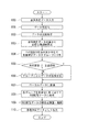
図2は上記の表面形状データ作成装置10を用いた表面形状データ作成処理の流れを示すフローチャートである。
まず、ステップ100において、表面測定データを測定データ入力部11から入力する。
表面測定データの入力は、表面形状計測装置1を測定データ入力部11に接続して自動的に入力してもよいし、あるいはハードディスクなどの高密度媒体を介して手作業で行ってもよい。
ステップ101では、データ可視化部12において、表面測定データのXY座標を画面の画素位置に割り当て、高さ位置を示すZ座標を8ビット256階調の濃度に割り当てた画像データを生成して、モニタ22に表示する。
FIG. 2 is a flowchart showing the flow of surface shape data creation processing using the surface shape data creation device 10 described above.
First, in
The surface measurement data may be input automatically by connecting the surface
In
ステップ102において、操作者がモニタ表示を見ながら行う操作入力部21の操作に基づいて、欠陥データ処理部14が表面形状のうねり成分を除去したり、欠損や異常データを適正なデータに置き換えて、皮絞模様として不適な傷の修正など、欠陥の修正を行う。
ステップ103において、測定データ分割処理部15では、あらかじめ設定してある1階調に対応させる高さSに基づいて、前ステップで欠陥修正された表面測定データの高さ(Z座標)の最低から最高までに必要な階調数を算出する。
In
In
そして、ステップ104で、測定データ分割処理部15は256階調幅に相当する分割高さを1単位として表面測定データの高さ(Z座標)を分割する分割数を求め、表面測定データを分割高さ(すなわち256階調分の高さ、)単位で分けて、分割数だけのグループ(データ群)に分割する。
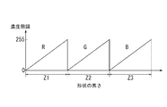
例えば1階調当りの高さSを1μmとして、図3に示すように、ステッチ部分の糸まで含んだ皮革モデルの表面測定データの高さ変化(形状高さ)が600μmであったとすると、分割高さ(1μm/1階調のとき256μm)単位で3グループに分割される。
この場合、表面測定データの高さの最低0から255μmの部分が第1グループZ1、続く256から511μmの高さ部分が第2グループZ2となり、残りの512から600μmを含む高さ部分が第3グループZ3として分割される。
In
For example, assuming that the height S per gradation is 1 μm, and the height change (shape height) of the surface measurement data of the leather model including the yarn at the stitch portion is 600 μm as shown in FIG. Divided into 3 groups in units of height (256 μm for 1 μm / 1 gradation).
In this case, the lowest portion of the height of the surface measurement data is the first group Z1, the subsequent height portion of 256 to 511 μm is the second group Z2, and the remaining height portion including 512 to 600 μm is the third group Z1. Divided as group Z3.
ステップ105では、操作者は表面測定データの測定面積が必要な製品面積をカバーしているか確認する。
測定面積が製品面積をカバーしているときはステップ107へ進み、測定面積が製品面積に対して小さいときはステップ106へ進む。
ステップ106では、操作者が操作入力部21を操作して、分割されたグループごとにモニタ22上で必要面積になるまで画像データを繰り返し配置してつなぎ合わせることにより、所要面積をカバーするように形状データ合成処理部16がデータの拡張合成を行う。
この合成時に、接続部分の境界を目立たないようにするボカシ処理も行なう。
このあと、ステップ107へ進む。
In
When the measurement area covers the product area, the process proceeds to Step 107, and when the measurement area is smaller than the product area, the process proceeds to Step 106.
In
At the time of this synthesis, blur processing is performed to make the boundary of the connection portion inconspicuous.
Then, it progresses to step 107.
ステップ107では、ローカルデータ変換部17が、測定データ分割処理部15で分割された各グループの表面測定データまたは形状データ合成処理部16で拡張合成されたデータ(以下、「グループの表面測定データ」で代表させる)をローカルデータに変換する。
ここでは、それぞれのグループの表面測定データを、分割高さ(256μm)を順次に累積した値を基準値とするローカルデータに変換する。
In
Here, the surface measurement data of each group is converted into local data using a value obtained by sequentially accumulating the divided heights (256 μm) as a reference value.
すなわち、スタートとしての第1グループZ1では、基準値を0として0〜255μmの範囲の表面測定データをそのままローカルデータとする。
第2グループZ2では基準値を256μmとして、256から511μmの範囲の表面測定データが0〜255μmのローカルデータとなる。
そして、第3グループZ3では基準値を512μm(=256+256)として、512から767μmの範囲の表面測定データが0〜255μmのローカルデータとなる。
That is, in the first group Z1 as a start, the surface measurement data in the range of 0 to 255 μm is set as local data as it is, with the reference value set to 0.
In the second group Z2, the reference value is set to 256 μm, and the surface measurement data in the range of 256 to 511 μm becomes local data of 0 to 255 μm.
In the third group Z3, the reference value is 512 μm (= 256 + 256), and the surface measurement data in the range of 512 to 767 μm is the local data of 0 to 255 μm.
続いて、ステップ108において、色成分合成処理部18は各グループのローカルデータを順次に色成分の異なるRGBのチャンネルに割り当て、これらのチャンネルのデータを合成してRGB画像データに変換する。RGB画像はモニタ22に表示される。
ステップ109において、操作者による操作入力部21の操作に基づいて、データ調整部19が、RGB画像データの解像度を製品の目標サイズに対応させたり、モニタ22上で製品形状への裁断処理などを行う。
Subsequently, in
In
このように最終調整されたRGB画像データが、ステップ110において、操作入力部21の操作に基づいて表面形状データとして表面形状データ出力部20から出力される。
なお、表面形状データの絞加工データ作成装置2への入力は、表面形状データ出力部20を直接絞加工データ作成装置2に接続して行うこともでき、あるいは媒体を介して手作業で行ってもよい。
The RGB image data finally adjusted as described above is output from the surface shape
The surface shape data can be input to the drawing
以上の処理により、表面形状データ出力部20から出力される表面形状データは3チャンネルから構成される1つのRGB画像データとなっており、Rチャンネルに第1グループZ1のデータ(ローカルデータ)が、Gチャンネルに第2グループZ2のデータが、そしてBチャンネルに第3グループZ3のデータが割り当てられている。
先に例示した1μm/1階調の場合には、図4に示すように、Rチャンネルのデータは表面測定データの高さ(形状の高さ)の0〜255μmの範囲部分(Z1)を256階調で示すものとなっており、Gチャンネルのデータは表面測定データの高さの256〜511μmの範囲部分(Z2)を256階調で示す。同様に、Bチャンネルのデータは表面測定データの高さの512以上の範囲部分(Z3)を256階調で示すものとなっている。したがってこのRGB画像データは8ビット表示が可能である。
Through the above processing, the surface shape data output from the surface shape
In the case of the 1 μm / 1 gradation exemplified above, as shown in FIG. 4, the R channel data has a range portion (Z1) of 0 to 255 μm of the height (shape height) of the surface measurement data. The G channel data indicates the range (Z2) in the range of 256 to 511 μm of the height of the surface measurement data with 256 gradations. Similarly, the B channel data indicates a range portion (Z3) of 512 or more heights of the surface measurement data in 256 gradations. Therefore, this RGB image data can be displayed in 8 bits.
なお、表面測定データの高さ変化が比較的に小さく、分割結果が2グループとなったときには、R、Gの2チャンネルに割り当てられ、2つの色成分をもつ画像データとされる。同様に、分割結果が1グループに収まったときには、色成分が1つだけの画像データとなる。 When the height change of the surface measurement data is relatively small and the division result is two groups, the image data is assigned to the two channels R and G and has two color components. Similarly, when the division result falls within one group, the image data has only one color component.
RGB画像データを形成する各チャンネルの情報は上記の構成となっているから、この表面形状データを受ける絞加工データ作成装置2では、一般化した次の形状高さ算出式により各チャンネルの階調Kに基づいて表面形状の高さZを算出することができる。
Rチャンネル: ZR =KR ×S
Gチャンネル: ZG =(256+KG )×S
Bチャンネル: ZB =(256+256+KB )×S
ただし、添え字はチャンネルを表わし、Sは前述のとおりあらかじめ設定された1階調当りの高さである。
Since the information of each channel forming the RGB image data has the above-described configuration, the drawing
R channel: Z R = K R × S
G channel: Z G = (256 + K G ) × S
B channel: Z B = (256 + 256 + K B ) × S
However, the subscript represents a channel, and S is the height per gradation set in advance as described above.
なお、表面形状データ作成装置10のデータ可視化部12、データ処理部13およびデータ調整部19等はCPUで構成することができ、とくにデータ処理部13の欠陥データ処理部14、測定データ分割処理部15、形状データ合成処理部16、ローカルデータ変換部17ならびに色成分合成処理部18はプログラムの形態で実現される。
Note that the
実施の形態は以上のように構成され、測定データ入力部11から入力された皮革モデルの表面測定データを、測定データ分割処理部15であらかじめ定めた1階調当りの高さSに256階調を乗じた分割高さ単位でグループに分割する。
そして、分割したそれぞれのグループにおける表面測定データを、ローカルデータ変換部17で分割高さを順次に累積した値を基準値とするローカルデータに変換してから、色成分合成処理部18で各ローカルデータをRGBのチャンネルに割り当て、チャンネルのローカルデータを合成してRGB画像データに変換し、このRGB画像データを表面形状データとするものとした。
The embodiment is configured as described above, and the surface measurement data of the leather model input from the measurement
Then, the surface measurement data in each divided group is converted into local data using a value obtained by sequentially accumulating the division heights in the local
これにより、図5の(a)に示す高さの小さい皮絞模様Aとともに高さの大きいステッチ糸Bを含む表面形状について、その高さの最低から最高まで全体を256階調のグレースケール画像で表現したとき、本来微細な表現が要求される皮絞模様部分が図5の(b)に示すようにギザギザの粗雑なものとなってしまう従来のものと比較して、1階調当りの高さSをあらかじめ設定した値に抑えているので、(a)の実際形状に極めて近い微細で滑らかな皮絞模様が表現される表面形状データが得られる。
そして、絞加工データ作成装置2に入力する場合、RGB画像データは合成された1つのデータとして扱われるので入力作業も一度で済み取り扱いが簡便であり、また絞加工データ作成装置2における加工データ化も一度にできるから、皮絞模様の高品質を確保しながら加工時間も短時間に抑えられる。
As a result, a 256-scale gray scale image of the entire surface shape from the lowest height to the highest height of the surface shape including the stitched pattern B having a large height as well as the skinned pattern A having a small height shown in FIG. Compared with the conventional one in which the squeezed pattern portion that is originally required to be finely expressed becomes jagged as shown in FIG. Since the height S is suppressed to a preset value, surface shape data expressing a fine and smooth skin-drawn pattern very close to the actual shape of (a) can be obtained.
When inputting to the drawing
また、測定データ入力部11から入力された表面測定データをデータ可視化部12で可視化してモニタ22に表示し、操作者による操作入力部21の操作に基づいて、欠陥データ処理部14が表面測定データの欠陥を修正するものとしたので、表面測定データに表れた表面形状のうねり成分の除去や、欠損や異常データの適正なデータへの置き換え、あるいは不適当な傷の修正などを、表面形状データ作成装置10上で表面形状データ作成途中に簡便に行うことができる。
Further, the surface measurement data input from the measurement
同様に操作入力部21の操作に基づいて、形状データ合成処理部16が、測定データ分割処理部15で分割したグループごとに当該グループの画像をつなぎ合わせてデータの拡張合成を行えるように構成しているので、この拡張合成されたデータを変換したローカルデータを各チャンネルへの割り当て対象とすることにより、表面測定データが面積の限定された皮革モデルからのものであっても、大面積用の表面形状データを簡単に作成することができる。
Similarly, on the basis of the operation of the
また、表面形状データはデータ調整部19によりRGB画像データの解像度調整や裁断処理を行ってから出力するので、画像データから画素位置と色濃度を情報として取り出し前述の形状高さZを算出するだけで絞の形状データとして使用できる。
Further, the surface shape data is output after the resolution adjustment or cutting processing of the RGB image data is performed by the
なお、実施の形態における各数値は例示であって、本発明は例示の数値に限定されない。また、表面測定データを皮革モデルのデータとして説明したが、モデルも皮革に限定されない。
実施の形態では256階調の8ビット表示を前提に説明したが、装置の処理速度やデータ容量の大きさ、あるいはモデルの模様特性に応じて16ビット表示その他を採用することを除外するものではなく、この場合にも、所定の分割高さで表面測定データを分割してそれぞれローカルデータに変換した上で多チャンネル色画像データとすることにより、表面形状の高さの全体を1つのグレースケール画像で表わすものと比較して格段の効果を奏する。
In addition, each numerical value in embodiment is an illustration, Comprising: This invention is not limited to the illustrated numerical value. Further, the surface measurement data has been described as leather model data, but the model is not limited to leather.
Although the embodiment has been described on the assumption that 256-bit 8-bit display is used, it does not exclude the adoption of 16-bit display or the like depending on the processing speed of the apparatus, the size of data capacity, or the pattern characteristics of the model. In this case as well, the surface measurement data is divided at a predetermined division height, converted to local data, and converted into multi-channel color image data. Compared to what is shown in the image, there is a remarkable effect.
また、測定データ分割処理部15で表面測定データを分割する際の、分割高さ算出に用いる1階調当りの高さSを例えば1μmあるいは1.3μmと例示したが、多くの皮絞模様の場合、2μm以下であれば商品性の高い表面形状が再現される。
Further, the height S per gradation used for dividing height calculation when the measurement data dividing
さらに、実施の形態では多チャンネル色画像データとして3グループを割り当て可能なRGB画像データを生成するものとしたが、そのほか例えばCMYK画像データとすれば4グループを割り当て可能となり、表面形状の高さ変化のとくに大きなモデルについても、微細で滑らかな模様が表現される表面形状データを得ることができる。 Furthermore, in the embodiment, RGB image data to which 3 groups can be assigned as multi-channel color image data is generated. However, for example, if CMYK image data is used, 4 groups can be assigned, and the surface shape changes in height. Even for a particularly large model, surface shape data expressing a fine and smooth pattern can be obtained.
1 表面形状計測装置
2 絞加工データ作成装置
10 表面形状データ作成装置
11 測定データ入力部
12 データ可視化部
13 データ処理部
14 欠陥データ処理部
15 測定データ分割処理部
16 形状データ合成処理部
17 ローカルデータ変換部
18 色成分合成処理部
19 データ調整部
20 表面形状データ出力部
21 操作入力部
22 モニタ
DESCRIPTION OF
Claims (8)
分割したそれぞれのグループにおける表面測定データを、前記所定の分割高さを順次に累積した値を基準値とするローカルデータに変換し、
該ローカルデータを互いに異なる色チャンネルに割り当て、
各ローカルデータが割り当てられた前記色チャンネルを合成して多チャンネル色画像データに変換して表面形状データとし、
前記所定の分割高さは、モデルの表面形状の高さを画像濃度で表わす際のあらかじめ定めた1階調当りの高さに所定の階調幅を乗じた値とすることを特徴とする表面形状データ作成方法。 Divide the surface measurement data of the model into groups with a predetermined division height unit,
The surface measurement data in each divided group is converted into local data using a value obtained by sequentially accumulating the predetermined division height as a reference value,
Assign the local data to different color channels,
The color channel to which each local data is assigned is combined and converted into multi-channel color image data to obtain surface shape data,
The predetermined divided height is a value obtained by multiplying a predetermined height per gradation when a height of the surface shape of the model is represented by an image density by a predetermined gradation width. Data creation method.
モニタ上で表面測定データの欠陥の修正を行うことを特徴とする請求項1に記載の表面形状データ作成方法。 The surface measurement data is visualized and displayed on a monitor before being divided by a predetermined divided height unit,
2. The surface shape data creation method according to claim 1, wherein a defect in the surface measurement data is corrected on a monitor.
前記多チャンネル色画像データがRGB画像データであって、前記分割したグループのローカルデータを割り当てる色チャンネルをR、GおよびBチャンネルから選択することを特徴とする請求項1または2に記載の表面形状データ作成方法。 The predetermined gradation width is 256,
3. The surface shape according to claim 1, wherein the multi-channel color image data is RGB image data, and a color channel to which the divided group of local data is assigned is selected from R, G, and B channels. Data creation method.
入力された表面測定データを、あらかじめ定めた1階調当りの高さに所定の階調幅を乗じた分割高さ単位でグループに分割する測定データ分割処理部(15)と、
それぞれのグループにおける表面測定データを、前記所定の分割高さを順次に累積した値を基準値とするローカルデータに変換するローカルデータ変換部(17)と、
各グループの前記ローカルデータを互いに異なる色チャンネルに割り当て、該色チャンネルを合成して多チャンネル色画像データに変換する色成分合成処理部(18)と、
前記多チャンネル色画像データを表面形状データとして出力する表面形状データ出力部(20)とを有することを特徴とする表面形状データ作成装置。 A measurement data input unit (11) for inputting the surface measurement data of the model;
A measurement data division processing unit (15) for dividing the input surface measurement data into groups in division height units obtained by multiplying a predetermined height per gradation by a predetermined gradation width;
A local data converter (17) for converting the surface measurement data in each group into local data using a value obtained by sequentially accumulating the predetermined division heights as a reference value;
A color component synthesis processing unit (18) that assigns the local data of each group to different color channels, synthesizes the color channels, and converts them into multi-channel color image data;
A surface shape data creating apparatus comprising a surface shape data output unit (20) for outputting the multi-channel color image data as surface shape data.
操作者が操作可能な操作入力部(21)と、
操作入力部の操作に基づいて、モニタ上で表面測定データの欠陥を修正可能な欠陥データ処理部(14)とを有することを特徴とする請求項4に記載の表面形状データ作成装置。 Furthermore, a data visualization unit (12) that visualizes the surface measurement data input from the measurement data input unit (11) and displays the surface measurement data on the monitor (22);
An operation input unit (21) operable by an operator;
5. The surface shape data creation device according to claim 4, further comprising a defect data processing unit (14) capable of correcting a defect of the surface measurement data on a monitor based on an operation of the operation input unit.
前記ローカルデータ変換部(17)は、前記形状データ合成処理部で合成されたデータを前記ローカルデータに変換することを特徴とする請求項5に記載の表面形状データ作成装置。 For each group divided by the measurement data division processing unit (15), on the basis of the operation of the operation input unit (21), the shape data composition processing unit (16) combines and synthesizes the images of the group on the monitor. With
6. The surface shape data creation device according to claim 5, wherein the local data conversion unit (17) converts the data synthesized by the shape data synthesis processing unit into the local data.
前記多チャンネル色画像データがRGB画像データであって、
前記色成分合成処理部(18)は、前記ローカルデータを割り当てる色チャンネルをR、GおよびBチャンネルから選択することを特徴とする請求項4から6のいずれか1に記載の表面形状データ作成装置。 The predetermined gradation width is 256,
The multi-channel color image data is RGB image data,
The surface shape data creation device according to any one of claims 4 to 6, wherein the color component synthesis processing unit (18) selects a color channel to which the local data is assigned from R, G, and B channels. .
Priority Applications (1)
| Application Number | Priority Date | Filing Date | Title |
|---|---|---|---|
| JP2008261585A JP4996573B2 (en) | 2008-10-08 | 2008-10-08 | Surface shape data creation method and surface shape data creation apparatus used therefor |
Applications Claiming Priority (1)
| Application Number | Priority Date | Filing Date | Title |
|---|---|---|---|
| JP2008261585A JP4996573B2 (en) | 2008-10-08 | 2008-10-08 | Surface shape data creation method and surface shape data creation apparatus used therefor |
Publications (2)
| Publication Number | Publication Date |
|---|---|
| JP2010092265A true JP2010092265A (en) | 2010-04-22 |
| JP4996573B2 JP4996573B2 (en) | 2012-08-08 |
Family
ID=42254913
Family Applications (1)
| Application Number | Title | Priority Date | Filing Date |
|---|---|---|---|
| JP2008261585A Expired - Fee Related JP4996573B2 (en) | 2008-10-08 | 2008-10-08 | Surface shape data creation method and surface shape data creation apparatus used therefor |
Country Status (1)
| Country | Link |
|---|---|
| JP (1) | JP4996573B2 (en) |
Cited By (1)
| Publication number | Priority date | Publication date | Assignee | Title |
|---|---|---|---|---|
| CN112132948A (en) * | 2019-06-06 | 2020-12-25 | 苏州苏大维格科技集团股份有限公司 | Image processing method, image processing apparatus, lithographic system, storage medium, and computer device |
Citations (3)
| Publication number | Priority date | Publication date | Assignee | Title |
|---|---|---|---|---|
| JPH07241909A (en) * | 1994-03-07 | 1995-09-19 | Dainippon Printing Co Ltd | System and method for manufacturing synthetic leater original plate |
| WO2005048847A1 (en) * | 2003-11-21 | 2005-06-02 | Hitachi Medical Corporation | Ultrasonograph |
| JP2007172132A (en) * | 2005-12-20 | 2007-07-05 | Fujitsu Ltd | Layout analysis program, layout analysis device and layout analysis method |
-
2008
- 2008-10-08 JP JP2008261585A patent/JP4996573B2/en not_active Expired - Fee Related
Patent Citations (3)
| Publication number | Priority date | Publication date | Assignee | Title |
|---|---|---|---|---|
| JPH07241909A (en) * | 1994-03-07 | 1995-09-19 | Dainippon Printing Co Ltd | System and method for manufacturing synthetic leater original plate |
| WO2005048847A1 (en) * | 2003-11-21 | 2005-06-02 | Hitachi Medical Corporation | Ultrasonograph |
| JP2007172132A (en) * | 2005-12-20 | 2007-07-05 | Fujitsu Ltd | Layout analysis program, layout analysis device and layout analysis method |
Cited By (1)
| Publication number | Priority date | Publication date | Assignee | Title |
|---|---|---|---|---|
| CN112132948A (en) * | 2019-06-06 | 2020-12-25 | 苏州苏大维格科技集团股份有限公司 | Image processing method, image processing apparatus, lithographic system, storage medium, and computer device |
Also Published As
| Publication number | Publication date |
|---|---|
| JP4996573B2 (en) | 2012-08-08 |
Similar Documents
| Publication | Publication Date | Title |
|---|---|---|
| JP7254324B2 (en) | IMAGE GENERATING APPARATUS AND IMAGE GENERATING METHOD FOR GENERATING INSPECTION IMAGE FOR PERFORMANCE ADJUSTMENT OF IMAGE INSPECTION SYSTEM | |
| US11321584B2 (en) | Information processing device, information processing program, and information processing method | |
| JP2010282611A (en) | Information processing apparatus, information processing method, and program | |
| KR20220002250A (en) | How to determine the layer thickness of a 3D model for additive manufacturing | |
| JP4500241B2 (en) | Color image processing device | |
| JP5294684B2 (en) | Manufacturing method and apparatus for three-dimensional relief | |
| JP4996573B2 (en) | Surface shape data creation method and surface shape data creation apparatus used therefor | |
| CN104690976B (en) | The column printing method of three-dimensional printing machine and system | |
| JP3945524B2 (en) | Key signal generation apparatus and method, image composition apparatus, and recording medium | |
| KR101958263B1 (en) | The control method for VR contents and UI templates | |
| JP6853259B2 (en) | Full-color data processing methods and equipment for 3D objects | |
| US20230045937A1 (en) | Generative system for the creation of digital images for printing on design surfaces | |
| US11573538B2 (en) | Layer configuration prediction method and layer configuration prediction apparatus | |
| JP2016117175A (en) | Image processor, image processing method, and program | |
| CN111462009B (en) | Bleeding point prediction method based on similarity of divided rectangular areas | |
| JPH05236347A (en) | Soft key generating device | |
| Surovi et al. | Process map generation of geometrically uniform beads using support vector machine | |
| JP2008009508A (en) | Method and apparatus for creating pseudo-gray-scale image | |
| CN111151887A (en) | Laser color carving operation method | |
| JP6749564B2 (en) | Processing evaluation apparatus, processing evaluation method, program for functioning as processing evaluation apparatus, and recording medium recording the program | |
| CN117416049B (en) | Printing equipment control method and system based on 3D printing technology | |
| JP6388489B2 (en) | Method and apparatus for creating data for surface processing | |
| WO2019054235A1 (en) | Information processing device, information processing method, and program | |
| US20230034028A1 (en) | Property display device, property display method, and non-transitory computer-readable medium | |
| TWI809705B (en) | Processing path generating method and device |
Legal Events
| Date | Code | Title | Description |
|---|---|---|---|
| A621 | Written request for application examination |
Free format text: JAPANESE INTERMEDIATE CODE: A621 Effective date: 20100928 |
|
| A977 | Report on retrieval |
Free format text: JAPANESE INTERMEDIATE CODE: A971007 Effective date: 20120130 |
|
| A131 | Notification of reasons for refusal |
Free format text: JAPANESE INTERMEDIATE CODE: A131 Effective date: 20120207 |
|
| A521 | Written amendment |
Free format text: JAPANESE INTERMEDIATE CODE: A523 Effective date: 20120403 |
|
| TRDD | Decision of grant or rejection written | ||
| A01 | Written decision to grant a patent or to grant a registration (utility model) |
Free format text: JAPANESE INTERMEDIATE CODE: A01 Effective date: 20120508 |
|
| A01 | Written decision to grant a patent or to grant a registration (utility model) |
Free format text: JAPANESE INTERMEDIATE CODE: A01 |
|
| A61 | First payment of annual fees (during grant procedure) |
Free format text: JAPANESE INTERMEDIATE CODE: A61 Effective date: 20120511 |
|
| FPAY | Renewal fee payment (prs date is renewal date of database) |
Free format text: PAYMENT UNTIL: 20150518 Year of fee payment: 3 |
|
| R150 | Certificate of patent (=grant) or registration of utility model |
Free format text: JAPANESE INTERMEDIATE CODE: R150 |
|
| LAPS | Cancellation because of no payment of annual fees |