JP2010089782A - Improvements for marine anchors - Google Patents
Improvements for marine anchors Download PDFInfo
- Publication number
- JP2010089782A JP2010089782A JP2009272095A JP2009272095A JP2010089782A JP 2010089782 A JP2010089782 A JP 2010089782A JP 2009272095 A JP2009272095 A JP 2009272095A JP 2009272095 A JP2009272095 A JP 2009272095A JP 2010089782 A JP2010089782 A JP 2010089782A
- Authority
- JP
- Japan
- Prior art keywords
- anchor
- line
- follower
- degrees
- slot
- Prior art date
- Legal status (The legal status is an assumption and is not a legal conclusion. Google has not performed a legal analysis and makes no representation as to the accuracy of the status listed.)
- Granted
Links
- 238000004873 anchoring Methods 0.000 claims abstract description 19
- 210000000078 claw Anatomy 0.000 claims description 77
- 239000002689 soil Substances 0.000 claims description 44
- 238000000034 method Methods 0.000 claims description 27
- 230000005484 gravity Effects 0.000 claims description 21
- 238000006073 displacement reaction Methods 0.000 claims description 16
- 230000035515 penetration Effects 0.000 abstract description 11
- 241000935974 Paralichthys dentatus Species 0.000 abstract 1
- 239000010687 lubricating oil Substances 0.000 description 16
- 238000009434 installation Methods 0.000 description 10
- 239000004927 clay Substances 0.000 description 6
- 230000000149 penetrating effect Effects 0.000 description 6
- 229910000831 Steel Inorganic materials 0.000 description 5
- 239000000853 adhesive Substances 0.000 description 5
- 230000001070 adhesive effect Effects 0.000 description 5
- 239000004576 sand Substances 0.000 description 5
- 239000010959 steel Substances 0.000 description 5
- 238000006243 chemical reaction Methods 0.000 description 4
- 230000007246 mechanism Effects 0.000 description 4
- 238000009933 burial Methods 0.000 description 3
- 230000006835 compression Effects 0.000 description 3
- 238000007906 compression Methods 0.000 description 3
- 239000000314 lubricant Substances 0.000 description 3
- 230000002093 peripheral effect Effects 0.000 description 3
- 238000005452 bending Methods 0.000 description 2
- 230000008878 coupling Effects 0.000 description 2
- 238000005303 weighing Methods 0.000 description 2
- 239000004677 Nylon Substances 0.000 description 1
- 239000006096 absorbing agent Substances 0.000 description 1
- 230000001133 acceleration Effects 0.000 description 1
- 230000009471 action Effects 0.000 description 1
- 230000001154 acute effect Effects 0.000 description 1
- 230000006978 adaptation Effects 0.000 description 1
- 238000010168 coupling process Methods 0.000 description 1
- 238000005859 coupling reaction Methods 0.000 description 1
- 230000007423 decrease Effects 0.000 description 1
- 230000003247 decreasing effect Effects 0.000 description 1
- 239000004519 grease Substances 0.000 description 1
- 239000000463 material Substances 0.000 description 1
- 238000012986 modification Methods 0.000 description 1
- 230000004048 modification Effects 0.000 description 1
- 229920001778 nylon Polymers 0.000 description 1
- 229920000728 polyester Polymers 0.000 description 1
- 230000008569 process Effects 0.000 description 1
- 230000001737 promoting effect Effects 0.000 description 1
- 238000011084 recovery Methods 0.000 description 1
- 239000013535 sea water Substances 0.000 description 1
- 238000007789 sealing Methods 0.000 description 1
- 238000000926 separation method Methods 0.000 description 1
- 235000013311 vegetables Nutrition 0.000 description 1
- 238000004804 winding Methods 0.000 description 1
Images


Classifications
-
- E—FIXED CONSTRUCTIONS
- E02—HYDRAULIC ENGINEERING; FOUNDATIONS; SOIL SHIFTING
- E02D—FOUNDATIONS; EXCAVATIONS; EMBANKMENTS; UNDERGROUND OR UNDERWATER STRUCTURES
- E02D5/00—Bulkheads, piles, or other structural elements specially adapted to foundation engineering
- E02D5/74—Means for anchoring structural elements or bulkheads
- E02D5/80—Ground anchors
- E02D5/803—Ground anchors with pivotable anchoring members
-
- B—PERFORMING OPERATIONS; TRANSPORTING
- B63—SHIPS OR OTHER WATERBORNE VESSELS; RELATED EQUIPMENT
- B63B—SHIPS OR OTHER WATERBORNE VESSELS; EQUIPMENT FOR SHIPPING
- B63B21/00—Tying-up; Shifting, towing, or pushing equipment; Anchoring
- B63B21/24—Anchors
- B63B21/26—Anchors securing to bed
-
- B—PERFORMING OPERATIONS; TRANSPORTING
- B63—SHIPS OR OTHER WATERBORNE VESSELS; RELATED EQUIPMENT
- B63B—SHIPS OR OTHER WATERBORNE VESSELS; EQUIPMENT FOR SHIPPING
- B63B21/00—Tying-up; Shifting, towing, or pushing equipment; Anchoring
- B63B21/24—Anchors
- B63B21/26—Anchors securing to bed
- B63B21/29—Anchors securing to bed by weight, e.g. flukeless weight anchors
-
- B—PERFORMING OPERATIONS; TRANSPORTING
- B63—SHIPS OR OTHER WATERBORNE VESSELS; RELATED EQUIPMENT
- B63B—SHIPS OR OTHER WATERBORNE VESSELS; EQUIPMENT FOR SHIPPING
- B63B21/00—Tying-up; Shifting, towing, or pushing equipment; Anchoring
- B63B21/24—Anchors
- B63B21/30—Anchors rigid when in use
- B63B21/32—Anchors rigid when in use with one fluke
-
- B—PERFORMING OPERATIONS; TRANSPORTING
- B63—SHIPS OR OTHER WATERBORNE VESSELS; RELATED EQUIPMENT
- B63B—SHIPS OR OTHER WATERBORNE VESSELS; EQUIPMENT FOR SHIPPING
- B63B21/00—Tying-up; Shifting, towing, or pushing equipment; Anchoring
- B63B21/24—Anchors
- B63B21/38—Anchors pivoting when in use
-
- B—PERFORMING OPERATIONS; TRANSPORTING
- B63—SHIPS OR OTHER WATERBORNE VESSELS; RELATED EQUIPMENT
- B63B—SHIPS OR OTHER WATERBORNE VESSELS; EQUIPMENT FOR SHIPPING
- B63B21/00—Tying-up; Shifting, towing, or pushing equipment; Anchoring
- B63B21/24—Anchors
- B63B21/38—Anchors pivoting when in use
- B63B21/40—Anchors pivoting when in use with one fluke
-
- E—FIXED CONSTRUCTIONS
- E02—HYDRAULIC ENGINEERING; FOUNDATIONS; SOIL SHIFTING
- E02D—FOUNDATIONS; EXCAVATIONS; EMBANKMENTS; UNDERGROUND OR UNDERWATER STRUCTURES
- E02D7/00—Methods or apparatus for placing sheet pile bulkheads, piles, mouldpipes, or other moulds
- E02D7/02—Placing by driving
- E02D7/06—Power-driven drivers
- E02D7/08—Drop drivers with free-falling hammer
-
- B—PERFORMING OPERATIONS; TRANSPORTING
- B63—SHIPS OR OTHER WATERBORNE VESSELS; RELATED EQUIPMENT
- B63B—SHIPS OR OTHER WATERBORNE VESSELS; EQUIPMENT FOR SHIPPING
- B63B21/00—Tying-up; Shifting, towing, or pushing equipment; Anchoring
- B63B21/24—Anchors
- B63B21/26—Anchors securing to bed
- B63B2021/262—Anchors securing to bed by drag embedment
-
- B—PERFORMING OPERATIONS; TRANSPORTING
- B63—SHIPS OR OTHER WATERBORNE VESSELS; RELATED EQUIPMENT
- B63B—SHIPS OR OTHER WATERBORNE VESSELS; EQUIPMENT FOR SHIPPING
- B63B21/00—Tying-up; Shifting, towing, or pushing equipment; Anchoring
- B63B21/24—Anchors
- B63B21/26—Anchors securing to bed
- B63B2021/265—Anchors securing to bed by gravity embedment, e.g. by dropping a pile-type anchor from a certain height
Abstract
Description
本発明は、船舶用アンカー(marine anchors)に関し、特に、ドラグ・エンベッドメント・アンカー(drag embedment anchor)および直接エンベッドメント・アンカー(direct embedment anchor)およびその固定手段(embedment means)に関する。 The present invention relates to marine anchors, and in particular, to a drag embedment anchor and a direct embedment anchor and its embedment means.
係留地点の海底(mooring bed)に固定させるための船舶用アンカーは、通常、係留地点の海底上の海中内に係留することにより保持される対象物に接続するためのアンカー・ライン(anchor line)に取り付けられる。アンカーは、アンカー・ライン取付け手段(例えば、シャックル)、および錨爪部材(fluke member)を通して、それにアンカー・ラインを取り付けるための負荷作動点(load application point)を含み、また、アンカーが動作中、負荷作動点から見ることができる錨爪部材の表面が最大投影面積を持つ第一の方向、および上記表面が最小の投影面積を持つ第二の方向を含む対称面を含む。従って、これらの方向においては、係留地点の海底の土壌面内におけるアンカーの移動に対する抵抗は、最大およびほぼ最小になる。アンカーの錨爪は、抵抗が最小の順方向(F)に沿って土壌内を前進する傾向がある。 Ship anchors for anchoring to the mooring point mooring bed are typically anchor lines for connecting to objects held by mooring in the sea above the mooring point seabed. Attached to. The anchor includes an anchor line attachment means (e.g., a shackle), and a load application point for attaching the anchor line to it through a flake member, and when the anchor is in operation, The claw member surface visible from the load operating point includes a symmetry plane including a first direction having a maximum projected area and a second direction in which the surface has a minimum projected area. Thus, in these directions, the resistance to anchor movement in the soil surface at the bottom of the mooring point is maximum and nearly minimum. Anchor claws tend to advance in the soil along the forward direction (F) with minimal resistance.
ドラグ・エンベッドメント・アンカーは、上記のように船舶用アンカーであり、アンカー・ライン固定手段の負荷作動点はアンカー上に位置していて、その結果、係留地点の海底の表面上に位置するアンカーに接続している、ライン上に掛かる水平方向に引く力により、アンカーはそれに貫通して係合するように傾き、錨爪部材の表面の最小投影面積の順方向(forward direction)に発生する変位の実質的な分力により、係留地点の海底の土壌内に食い込むことになる。それにより、アンカーが、係留地点の海底の土壌内に食い込むと、アンカーは湾曲した埋設軌跡(burial trajectory)に沿って移動することになる。それ故、負荷作動点の位置により、アンカー・ライン取付け手段はアンカーの固定手段として機能することができる。 The drag embedment anchor is a marine anchor as described above, and the load operating point of the anchor line fixing means is located on the anchor, and as a result, the anchor located on the seabed surface of the mooring point. The displacement that occurs in the forward direction of the minimum projected area of the surface of the claw member is tilted so that the anchor is penetrated and engaged by the horizontal pulling force applied to the line connected to Due to the substantial component force, it will bite into the soil at the bottom of the mooring point. As a result, when the anchor bites into the soil at the bottom of the mooring point, the anchor moves along a curved burial trajectory. Therefore, depending on the position of the load operating point, the anchor line attaching means can function as an anchor fixing means.
例えば、EP−A−0161190のような直接エンベッドメント・アンカーは、上記のように、取り付けられたアンカー・ラインに掛かる引く力によりアンカーが係留地点の海底の土壌内に食い込んだ場合、錨爪部材の最大投影面積の方向に移動しようとするように位置するアンカー・ライン取付け手段の負荷作動点を持つ船舶用アンカーである。このようになっているために、海底に食い込んだアンカーは、上向きに、係留地点の海底面を貫通する軌跡を通ることになり、その結果、アンカー・ラインおよびアンカー・ライン取付け手段が、アンカーの固定手段として機能するのを防止する。それ故、アンカーを錨爪部材の最小の投影面積の順方向に係留地点の海底の土壌に係合させ、深く押し込むために、フォロア(follower)と呼ばれる押し込み部材を備える別の固定手段が使用される。 For example, a direct embedment anchor such as EP-A-0161190 is a claw member when the anchor bites into the soil at the bottom of the mooring point due to the pulling force applied to the attached anchor line as described above. A marine anchor having a load operating point of an anchor line mounting means positioned so as to move in the direction of the maximum projected area. Because of this, the anchor that has digged into the seabed will go upward and through a trajectory that penetrates the bottom of the mooring point, so that the anchor line and the anchor line attachment means are Prevents functioning as a fixing means. Therefore, another anchoring means with a pushing member called a follower is used to engage the anchor with the soil at the bottom of the mooring point in the forward direction of the smallest projected area of the claws and push it deeply. The
上記各アンカーを、以後、それぞれ、上記タイプの船舶用アンカー、ドラグ・エンベッドメント・アンカーまたは直接エンベッドメント・アンカーと呼ぶことにする。 Each of the anchors will be hereinafter referred to as a marine anchor, a drag embedment anchor, or a direct embedment anchor, respectively.
これらのアンカーは欠点を持っている。すなわち、ドラグ・エンベッドメント・アンカーは、係留地点の海底の面の下で必要な固定深さに達するのに、場合によっては、許容できない変位の水平分力を必要とするし、直接エンベッドメント・アンカーは、係留地点の海底を破壊して、最終的には破局にいたるような過負荷が掛かった場合に、固定深さが次第に浅くなるという欠点がある。さらに、直接エンベッドメント・アンカーは、アンカー・ハンドリング船(anchor−handling vessel)上に取付けた場合に、破損し易く、取扱いが難しい長いフォロアにより海底に押し込んでやらなければならない。 These anchors have drawbacks. That is, the drag embedment anchor may require a horizontal component of unacceptable displacement in some cases to reach the required fixed depth below the surface of the seabed at the mooring point. Anchors have the disadvantage that the anchoring depth gradually decreases when the seabed at the mooring point is destroyed and an overload that eventually leads to catastrophe is applied. In addition, direct embedment anchors must be pushed into the ocean floor by long followers that are prone to breakage and are difficult to handle when mounted on an anchor-handling vessel.
本発明の目的は、とりわけ、これらの欠点を軽減することである。広い意味でいうと、本発明は、海底面の下の最初の埋設位置に埋設された後で、アンカー・ライン取付け手段を通して、アンカー・ラインにより引きずられた場合に、埋設軌跡を通る船舶用アンカーと、最初の埋設位置を確立するための固定手段とを備えるアンカー装置を広く提供する。 The object of the present invention is, among other things, to alleviate these drawbacks. In a broad sense, the present invention relates to a marine anchor that passes through an embedding trajectory when it is dragged by an anchor line through an anchor line attachment means after being embedded at an initial embedding position below the sea floor. And an anchor device comprising a fixing means for establishing an initial embedded position.
本発明の第一のアスペクトによると、すでに説明し、係留地点の海底の表面より下で動作するように構成されている上記船舶用アンカーは、ドラグ・アンカーである。上記ドラグ・アンカーの特徴は、負荷作動点および負荷作動点から見ることができる錨爪部材の表面の重心を含む直線が、順方向(F)と、柔らかい粘着性の土壌内で動作する場合には、68度から85度の範囲の、また非粘着性の土壌内で動作する場合には、50度から65度の範囲の順方向開放角(forward−opening angle)(β)を形成し、それにより、アンカー錨爪部材重心が、係留地点の海底面の下に、上記最大投影面積の平方根の少なくとも二倍埋設した場合、アンカー・ライン取付け手段の負荷作動点のところで、アンカー・ラインによりアンカーに加えられた引く力により、アンカーが、第二の順方向の変位の実質的な分力で、係留地点の海底の土壌内を移動させることである。 According to a first aspect of the present invention, the marine anchor already described and configured to operate below the surface of the seabed at the mooring point is a drag anchor. The feature of the drag anchor is that the load operating point and the straight line including the center of gravity of the surface of the claw member that can be seen from the load operating point operate in the forward direction (F) and in soft, sticky soil. Forms a forward-opening angle (β) in the range of 68 to 85 degrees and, when operating in non-sticky soil, in the range of 50 to 65 degrees; Thus, when the anchor claw member center of gravity is buried under the sea bottom of the mooring point at least twice the square root of the maximum projected area, the anchor line is anchored by the anchor line at the load operating point of the anchor line attachment means. The pulling force applied to the anchor causes the anchor to move through the soil at the bottom of the mooring point with a substantial component of the second forward displacement.
好適には、上記第二の順方向の変位の上記の実質的な分力は、実際の変位の35%を超えることが好ましい。 Preferably, the substantial component force of the second forward displacement is greater than 35% of the actual displacement.
さらに、好適には、上記第二の順方向の変位の上記実質的な分力は、実際の変位の50%を超えることが好ましい。 Further preferably, the substantial component of the second forward displacement is preferably greater than 50% of the actual displacement.
好適には、上記重心角は、柔らかい粘着性の土壌内で動作する場合には、80度以下であることが好ましく、非粘着性の土壌内で動作する場合には、60度以下であることが好ましい。 Preferably, the barycentric angle is preferably 80 degrees or less when operating in soft and cohesive soil, and 60 degrees or less when operating in non-sticky soil. Is preferred.
好適には、上記ドラグ・アンカーは、さらに、上記アンカーの対称面に直角であり、錨爪部材の先端部および負荷作動点を含む面が、順方向(F)と、柔らかい粘着性の土壌内で動作する場合には、95度以上の、非粘着性の土壌内で動作する場合には、85度以上の順方向開放先端角(α)を形成することを特徴とすることが好ましい。 Preferably, the drag anchor is further perpendicular to the symmetry plane of the anchor, and the surface including the tip of the claw member and the load operating point is in the forward direction (F) and in the soft sticky soil. When operating in non-adhesive soil of 95 degrees or more, it is preferable to form a forward open tip angle (α) of 85 degrees or more.
好適には、上記先端角は、柔らかい粘着性の土壌内で動作する場合には100度以上であり、非粘着性の土壌内で動作する場合には、90度以上であることが好ましい。 Preferably, the tip angle is 100 degrees or more when operating in soft adhesive soil, and 90 degrees or more when operating in non-adhesive soil.
好適には、本発明の第一のアスペクトによるドラグ・アンカーは、それにしっかりと取り付けられていて、上記対称面に平行なプレート状のシャンク部材を含む錨爪を備えることが好ましい。 Preferably, the drag anchor according to the first aspect of the present invention comprises a claw comprising a plate-like shank member secured to it and parallel to the plane of symmetry.
好適には、上記プレート状のシャンク部材は、アンカー・ライン取付け手段の、その内部で摺動可能な細長いスロットを含むことが好ましい。この場合、アンカー・ライン取付け手段の負荷作動点として機能する上記スロットの先端部は、引きずるという動作でアンカーをより深く埋設することができ、代理のアンカー・ライン取付け手段の負荷作動点として機能する上記錨爪の後縁部の方に位置する後端部は、上記順方向のほぼ反対方向に、後方に向けアンカーを容易に回収することができる。 Preferably, the plate-like shank member includes an elongated slot slidable within the anchor line attachment means. In this case, the tip of the slot that functions as the load operating point of the anchor line attaching means can embed the anchor deeper by dragging, and functions as the load operating point of the substitute anchor line attaching means. The rear end portion located toward the rear edge of the claw can easily recover the anchor toward the rear in a direction substantially opposite to the forward direction.
好適には、スライド停止手段は、上記取付け手段を上記負荷作動点に拘束するために、上記スロットの先端の直後に設置することが好ましい。 Preferably, the slide stop means is installed immediately after the end of the slot in order to restrain the attachment means at the load operating point.
好適には、上記スライド停止手段が、上記アンカー・ライン取付け手段と協働して動作する解放手段を含み、そうすることにより、上記取付け手段が上記スロットを上記錨爪の後方にスライドすることができるように、上記取付け手段の回転変位により、上記スライド停止手段を解放することが好ましい。 Preferably, the slide stop means includes release means that operate in cooperation with the anchor line attachment means so that the attachment means slides the slot behind the claw. Preferably, the slide stop means is released by rotational displacement of the attachment means.
好適には、上記アンカー・ライン取付け手段は、細長いシャックルを備えることが好ましい。 Preferably, the anchor line attachment means comprises an elongated shackle.
さらに好適には、上記アンカー・ライン取付け手段は、取付け点をアンカー・ラインに接続する働きをしている一方の端部に持ち、上記シャンク部材内の上記スロット内で摺動可能にまた回転可能に係合する働きをしているピン部材を担持する、もう一方の端部にクレビス(clevis)を持つ細長い部材を備えることが好ましい。 More preferably, the anchor line attachment means has an attachment point at one end which serves to connect the anchor line and is slidable and rotatable within the slot in the shank member. Preferably, it comprises an elongated member carrying a clevis at the other end which carries a pin member which serves to engage.
好適には、上記シャンク部材は、上記負荷作動点に中心を持つアーチ状の表面を含み、上記細長い部材は、上記アーチ状の表面上に摺動可能に係合することができるストッパを含み、それにより、負荷作動点を中心とする細長い部材の回転により、ストッパの移動方向が、そこでピン部材がスロット内を自由にスライドできる点で、スロットに平行になるまで、上記ピン部材が上記スロット内の負荷作動点に保持されるストッパを持つことが好ましい。 Preferably, the shank member includes an arcuate surface centered at the load operating point, and the elongate member includes a stopper that is slidably engageable on the arcuate surface; Thereby, rotation of the elongated member about the load operating point causes the stopper member to move in the slot until the stopper moves in a direction parallel to the slot where the pin member can freely slide in the slot. It is preferable to have a stopper held at the load operating point.
好適には、上記アンカーは、上記ピン部材が上記負荷作動点に位置した場合、上記シャンク部材に対して所定の位置で上記細長い部材の回転を停止するための解放可能な回転停止手段を含むことが好ましい。 Preferably, the anchor includes releasable rotation stopping means for stopping rotation of the elongated member at a predetermined position with respect to the shank member when the pin member is located at the load operating point. Is preferred.
好適には、上記細長い部材の長さは、上記解放可能な回転停止手段により上記部材が回転を中止した場合に、上記対称面に直角でありまた上記錨爪部材の先端部と細長い部材上の上記取付け点とを含む面が上記第二の方向に対して順方向開放角を形成し、その角度が95度以下であり、さらに好適には75度以下であるような長さであることが好ましい。 Preferably, the length of the elongate member is perpendicular to the plane of symmetry when the member stops rotating by the releasable rotation stop means and is on the tip of the claw member and the elongate member. The surface including the attachment point forms a forward opening angle with respect to the second direction, and the angle is 95 degrees or less, more preferably 75 degrees or less. preferable.
本発明の第二のアスペクトによると、本発明の船舶用アンカーおよび固定手段は、上記のドラグ・エンベッドメント・アンカーおよび上記ドラグ・アンカーの中の一つと、それに取り外し可能に取り付けられていて、アンカーの錨爪部材重心が係留地点の海底面の下に上記最大投影面積の平方根の少なくとも二倍埋設し、それにより、埋設したアンカーからフォロア部材を取り外した後で、アンカー・ラインの上に掛かる引く力により、アンカーが上記第二の方向に変位の実質的な分力により係留地点の海底の土壌内で移動しようとするまで、上記アンカー・ライン取付け手段の負荷作動点から見ることができる上記錨爪部材の表面の最小の投影面積の上記第二の順方向に上記アンカーを実質的に押すことができる細長いフォロア部材とを備える。 According to a second aspect of the present invention, the marine anchor and the fixing means of the present invention are removably attached to one of the drag embedment anchor and the drag anchor, and the anchor The claw member's center of gravity is buried under the sea bottom of the mooring point at least twice the square root of the maximum projected area, thereby removing the follower member from the buried anchor and then pulling over the anchor line The anchor can be seen from the load operating point of the anchor line attachment means until the anchor attempts to move in the soil at the bottom of the mooring point by a substantial component of displacement in the second direction. An elongated follower member capable of substantially pushing the anchor in the second forward direction with a minimum projected area on the surface of the claw member. That.
本発明の第三のアスペクトによると、本発明の船舶用アンカーおよび固定手段は、ドラグ・エンベッドメント・アンカーおよび直接エンベッドメント・アンカーおよび上記ドラグ・アンカーの中の一つと、それに取り外し可能に取り付けられていて、係留地点の海底にほぼ上記第二の方向に上記アンカーを押すことができる細長いフォロア部材とを備えていて、上記アンカーおよび上記細長いフォロアの中の少なくとも一方が、それを中心にしてアンカーが枢動できる反動支点(reaction fulcrum)を供給することができることを特徴とする。 According to a third aspect of the present invention, the marine anchor and the anchoring means of the present invention are removably attached to one of the drag embedment anchor and the direct embedment anchor and the drag anchor. An elongate follower member capable of pushing the anchor substantially in the second direction at the bottom of the mooring point, wherein at least one of the anchor and the elongate follower is anchored about the anchor It is possible to provide a reaction fulcrum that can pivot.
好適には、上記船舶用アンカーは、取り付けられているアンカー・ラインにより、アンカーに引く力が加えられた場合、上記支点を中心にして枢動することが好ましい。 Preferably, the marine anchor preferably pivots about the fulcrum when a pulling force is applied to the anchor by an attached anchor line.
好適には、船舶用アンカーを直接固定するための上記固定手段は、船舶用アンカーに取り外し可能に取り付けることができる細長いフォロア部材と、上記フォロア部材により、係留地点の海底内に押された場合、それを中心にしてアンカーが枢動することができる反動支点を備えることが好ましい。 Preferably, the fixing means for directly fixing the marine anchor includes an elongated follower member that can be removably attached to the marine anchor, and when pushed by the follower member into the seabed at the mooring point, It is preferable to provide a reaction fulcrum on which the anchor can pivot.
本発明の第四のアスペクトによると、本発明の船舶用アンカーおよび固定手段は、上記船舶用アンカーと、それに取り外し可能に取り付けられていて、上記ほぼ第二の方向に上記アンカーを押すことができ、さらに、例えば、アンカー・ハンドリング船のスタン・ローラ(stern roller)のような湾曲表面を横切ることにより、横方向の力が加わった場合に、損傷を受けることなく、元の状態に戻ることができるように曲がることができる細長いフォロア部材を備える。 According to the fourth aspect of the present invention, the marine anchor and the fixing means of the present invention are attached to the marine anchor and the detachable thereto, and can push the anchor in the substantially second direction. In addition, crossing a curved surface, such as an anchor handling ship's stern roller, can return to its original state without damage when a lateral force is applied. An elongated follower member that can be bent as much as possible.
本発明の第五のアスペクトによると、本発明の船舶用アンカーを直接埋設するための固定手段は、船舶用アンカーに取り外し可能に取り付けることができ、さらに、例えば、アンカー・ハンドリング船のスタン・ローラのような湾曲表面を横切ることにより横方向の力が加わった場合に、損傷を受けることなく、元の状態に戻ることができるように曲がることができる細長いフォロア部材を備える。 According to a fifth aspect of the present invention, the fixing means for directly embedding the marine anchor of the present invention can be removably attached to the marine anchor, and further, for example, a stun roller of an anchor handling ship When a lateral force is applied by crossing the curved surface, a long and narrow follower member that can be bent so as to return to its original state without being damaged is provided.
好適には、上記フォロア部材は、アンカーを海中に沈めたり、引き上げたりするためのライン(lowering and recovering line)に取り付けられている下端部セグメントを含み、また、上記下端部セグメントにより支持されている複数の本体セグメントを含むことが好ましい。 Preferably, the follower member includes and is supported by a lower end segment attached to a lowering and recovering line for sinking or lifting the anchor into the sea. It preferably includes a plurality of body segments.
好適には、上記本体セグメントは、上記のアンカーを海中に沈めたり、引き上げたりするためのラインをほぼ囲んでいることが好ましい。 Preferably, the body segment substantially surrounds a line for sinking or lifting the anchor into the sea.
好適には、上記セグメントは、隣接するセグメント上の対応する凹部に合う、一つのセグメント上の凸状突起により一体になっていることが好ましい。 Preferably, the segments are united by convex protrusions on one segment that fit into corresponding recesses on adjacent segments.
好適には、上記のアンカーを海中に沈めたり、引き上げたりするためのラインは、上記本体セグメントを通る軸線を形成することが好ましい。 Preferably, the line for sinking or lifting the anchor into the sea forms an axis through the body segment.
好適には、上記本体セグメント内の上記ラインの少なくとも一部は、ロープおよびチェーンの中の少なくとも一方を備えることが好ましい。 Preferably, at least part of the line in the body segment comprises at least one of a rope and a chain.
好適には、上記本体セグメント内の上記ラインの少なくとも一部は、例えば、ポリエステル・ロープのような弾力性を持つ、引き延ばすことができる材料からできていることが好ましい。 Preferably, at least a portion of the line in the body segment is made of a stretchable material having elasticity such as, for example, a polyester rope.
好適には、上記フォロアが垂直に垂れ下がった時に、上記本体セグメント内の上記ラインが張力により延びた場合、上記ラインが、上部本体セグメントと上記ラインとの間で作動しているライン停止手段によりたるむことが防止され、それにより、上記本体セグメントが、上記フォロアの少なくとも一部が、海底面との接触により支えられた場合、上記細長いフォロア部材に、座屈に耐えることができるだけのある程度の横方向の剛性を与える、軸線方向に圧縮された状態に維持されることが好ましい。 Preferably, when the line in the body segment extends due to tension when the follower hangs vertically, the line sags by line stop means operating between the upper body segment and the line. The body segment so that the elongated follower member is able to withstand buckling if at least a portion of the follower is supported by contact with the sea floor. It is preferable to maintain the state compressed in the axial direction, which gives the rigidity of
好適には、上記上部本体セグメント上の上記ライン停止手段は解放することができ、それにより、上記フォロアが引き上げられ、上記湾曲面上で湾曲した場合、上記ラインがフォロア内で解放され、フォロアの湾曲によりラインが過度に延びるのを防止するために、上記ラインと上部本体セグメントとの間で相対的な軸線方向の動きができることが好ましい。 Preferably, the line stop means on the upper body segment can be released so that when the follower is pulled up and curved on the curved surface, the line is released in the follower and the follower's In order to prevent the line from extending excessively due to the curvature, it is preferable that a relative axial movement is possible between the line and the upper body segment.
好適には、上記ライン停止手段は、上記湾曲面と接触しているアクチュエータの移動により解放することができるものであることが好ましい。 Preferably, the line stop means can be released by movement of an actuator in contact with the curved surface.
好適には、上記ライン停止手段は、上記ライン、および上記上部本体セグメントの中の一方の上に位置する歯状部材であって、上記ライン、および上部本体セグメントの他方の上に位置する凹状部材の凹部に係合する歯状部材を含むことが好ましい。 Preferably, the line stop means is a tooth-like member located on one of the line and the upper body segment, and is a concave member located on the other of the line and the upper body segment. It is preferable to include a tooth-like member that engages with the recess.
本発明の第六のアスペクトによると、上記ドラグ・アンカーを固定するための本発明の固定手段は、細長い硬質な部材アンカー・ライン取付け手段により、それに取り付けられているアンカー・ラインを備えることが好ましい。上記細長い部材は、アンカー・ラインに取り付ける働きをする一方の端部のところの第一の取付け点と、アンカー上の上記アンカー・ライン取付け手段の負荷作動点に取り付けるための他方の端部のところの第二の取付け点を有し、また、上記錨爪部材の先端部および第一の取付け点を含む上記対称面に直角な面が、アンカーがその上を引きずられた場合には、係留地点の海底面への埋設を促進するために、75度以下であるが、上記錨爪部材が係留地点の海底の土壌内に埋設された場合には、上記錨爪部材上の土壌の負荷により解放される、上記第二の方向に対する順方向開放角を形成するように、アンカーに対して細長い部材を保持するための、解放可能な回転停止手段を持つ。 According to a sixth aspect of the present invention, the securing means of the present invention for securing the drag anchor preferably comprises an anchor line attached thereto by an elongated rigid member anchor line attaching means. . The elongate member has a first attachment point at one end that serves to attach to the anchor line and at the other end for attachment to the load operating point of the anchor line attachment means on the anchor. And when the anchor is dragged over the surface perpendicular to the symmetry plane including the tip of the claw member and the first attachment point, the mooring point In order to promote the embedding of the claws on the bottom of the sea, it is 75 degrees or less. And a releasable rotation stop means for holding the elongate member against the anchor so as to form a forward opening angle with respect to the second direction.
好適には、上記細長い硬質の部材は、上記第二の取付け点のところに、上記ドラグ・アンカーの上記シャンク部材の上記スロット内で摺動可能でかつ回転可能に係合させる働きをするピン部材を担持するクレビスを持つことが好ましい。 Preferably, the elongate rigid member is slidably and rotatably engaged within the slot of the shank member of the drag anchor at the second attachment point. It is preferable to have a clevis that carries.
添付の図面を参照しながら、本発明の実施形態について説明するが、この説明は単に例示としてのものに過ぎない。 While embodiments of the present invention will be described with reference to the accompanying drawings, this description is merely exemplary.
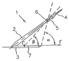
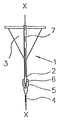
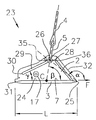
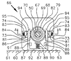
係留地点の海底の土壌内で引きずることによる固定(drag embodement)を行うための周知のドラグ・エンベッドメント・アンカー1(図1、図2、図3)は、一方の端部で、三角形のプレート状またはブレード状の錨爪3に接続し、他方の端部で、シャンク2内の孔部6内にピンで枢動できるように固定されているシャックル5により、アンカー・ライン4に接続しているシャンク2を備える。錨爪部材3は平らな形をしていて、アンカー1は、シャンク2内の孔部6の中心と、錨爪3のセンターライン7とを含む対称面X−Xに対して対称になっている。センターライン7は、錨爪3に沿って、シャンク2および錨爪3の間の接続から遠ざかる方向を向いている錨爪3の順方向Fに平行になっている。シャックルの孔部6の中心および錨爪3の先端部を含む、対称面X−X内の直線は、順方向Fに対して順方向開放先端角αを形成する。シャックル孔部6の中心と、錨爪3の上面の重心Cとを含む対称面X−X内の直線は、錨爪3の順方向Fに対して順方向開放重心角βを形成する。
The known drag embedment anchor 1 (FIG. 1, FIG. 2, FIG. 3) for drag embedding by dragging in the seabed soil at the mooring point is a triangular plate at one end. Connected to the
R.S.ダンフォース(Danforth)の英国特許第2,674,969号(UK Patent 2,674,969)が、このようなドラグ・エンベッドメント・アンカーについて詳細に開示している。上記英国特許は、αおよびβの範囲を、それぞれ、50度から80度、および25度から55度としている。ダンフォースは、英国特許第553,235号(UK 553,235)において、角度αおよびβの重要性について説明し、角度αが75度を超えると係留地点の海底面とアンカーとの間の信頼できる係合が失われ、アンカーを柔らかい泥からなる海底で使用する場合には、角度βを最高65度にすることができると述べている。ダンフォースが述べているこのような角度範囲は、現在まで、ドラグ・エンベッドメント・アンカーの幾何学的形状が、海底面を貫通するためのこの重要な要件により制限されてきたことを示している。 R. S. Danforth UK Patent No. 2,674,969 (UK Patent 2,674,969) discloses in detail such a drag embedment anchor. The British patent has α and β ranges of 50 to 80 degrees and 25 to 55 degrees, respectively. Danfors, in British Patent No. 553,235 (UK 553,235), explains the importance of angles α and β, and trust between the seabed at anchor point and anchor when angle α exceeds 75 degrees. It states that the angle β can be up to 65 degrees when the possible engagement is lost and the anchor is used on a soft mud seabed. The angular range described by Danforth shows that to date, the geometry of the drag embedment anchor has been limited by this important requirement to penetrate the seabed. .
ドラグ・エンベッドメント・アンカー1は、係留地点の海底面8(図4)上に設置され、アンカー・ライン4により水平方向に引かれる。先端角αが75度より小さい場合には、錨爪3は、最初、海底面8を貫通し、その後で、アンカーの錨爪の重心Cは、最終的には、海底面8の制限深さdで水平になる係留地点の海底の土壌10内の湾曲した軌跡9を通る。係留地点の海底上のスペースが制限される場合には、所望の深さまで貫通する際の、かなりの水平方向の変位dd(引きずる距離(drag distance))は許容されない。
The
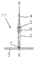
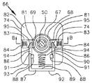
係留地点の海底に直接固定するための周知の直接エンベッドメント・アンカー11(図5、図6、図7)は、一方の端部で、ほぼ長方形のプレート錨爪3に接続し、他方の端部で、シャンク2の孔部6内に、ピンで枢動できるように固定されているシャックル5によりアンカー・ライン4に接続している三角形のプレート・シャンク2を備える。錨爪3は平らな形をしていて、アンカー11は、プレート・シャンク2内のシャックル孔部6と、錨爪3のセンターライン7とを含む対称面X−Xに対して対称になっている。順方向Fは、錨爪3のセンターライン7に平行になっている。シャックルの孔部6の中心と、錨爪3の上部面の重心Cとを含む対称面X−X内の直線は、センターライン7に対して90度の角度を形成する。
A well-known direct embedment anchor 11 (FIGS. 5, 6, and 7) for fixing directly to the seabed at the mooring point is connected to a substantially
直接エンベッドメント・アンカー11は、それに取り外し可能に取り付けられている硬質の細長いフォロア部材13により、係留地点の海底10に垂直に押し込まれる(図8)。フォロア部材13は、それに取り付けられていて、ライン16から吊り下げられている、パイル駆動ハンマ15により打ち込まれるパイル14を備える。錨爪3の面積Cの中心が、係留地点の海底面8の下の所望の深さdまで打ち込まれたとき、パイルの打ち込みは完了する。その後で、ライン16により引き上げることにより、パイル14はアンカー11から外れ、アンカー・ライン4より加えられる斜め方向の引き上げる力によりアンカー11は回転し、同時に、アンカー・ライン4の力の作用線が、錨爪3の重心Cを通過するまで距離kだけ上方に移動する。直接エンベッドメント・アンカー11は、距離dから実際に到達した埋設深さkを差し引いた位置におけるアンカー・ライン4内の張力による移動に最大の抵抗が発生する方向を向いている。しかし、アンカー・ライン4にこの最大抵抗より大きな負荷が掛かった場合には、直接エンベッドメント・アンカーは、海底面8まで上に向かって移動し、海底面8を破壊するまで、アンカー・ライン4の方向に移動し、これにより重大な損傷を蒙る。このため、このタイプのアンカーの場合には、通常、安全設置係数を2としなければならない。
The
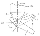
本発明の第一の実施形態の場合には、好適な高い値において角度β(図1)を持つ上記記載のドラグ・エンベッドメント・アンカー1は、シャンク2上のピボット17(図9)のところで、アンカーを海中に沈めたり引き上げたりするためのライン16により吊り下げられている重い細長いフォロア部材13の下端部19の協働クレビス18に、取り外し可能でかつ枢動可能に取り付けられている。錨爪3のセンターライン7は、錨爪3が、フォロア13の長手方向軸線20の方向の投影面積を最小にし、アンカー1の最小投影面積の合計面積C1(図2)の中心およびシャックル5が軸線20と一直線上にくるように、フォロア13の長手方向軸線20に、最初、平行に配置される。アンカー1が所望の向きに固定されるクレビス18のストッパ21と接続するシャンク2により捕捉されるまで、軸線20に平行なアンカー・ライン4上に働く引く力により、アンカー1は、ピボット17を中心にして回転する。クレビス18およびシャンク2を貫通する小さなシャーピン(shear pin)22(図10)が、上記回転がスタートする前、軸線20に平行な状態で錨爪3のセンターライン7によってクレビス18にアンカー1を保持する働きをする。
In the case of the first embodiment of the invention, the above described
アンカー1の固定(図9)は、単に、フォロア13に取り付けられているアンカー1を係留地点の海底10の表面8に下ろし、継続的に、アンカー・ライン4を含むライン16を緩めた状態に維持することにより行う。アンカー1は、錨爪3の重心Cが、錨爪3の最大投影面積の平方根の2倍を超える係留地点の海底面8の下の所望の深さdに到達するまで、重いフォロア13の重量により係留地点の海底10の中に降下する。この作業は、フォロア13の質量を正しく選択することにより行われる。その後、ライン16を緩めた状態にしておいて、アンカー・ライン4を引き上げる。反動素子(reaction element)を設置するために、フォロア13を正しい位置に設置したままで、ライン4の引上げ張力によりシャーピン22(図10)を分離し、シャンク2がクレビス18のストッパ21により捕捉されるまで、係留地点の海底の土壌10内で、ピボット17を中心にしてアンカー1を回転する。それ故、錨爪3の重心Cは、海底面8の下の深さdより少し深いところに移動し、図4に示す埋設深さkが浅くなる不都合が避けられる。その後で、フォロア13は、ライン16を引き上げることによってアンカー1から外され、アンカー・ライン4に斜めの力が加わり、その結果、土壌10内に深く入り、下向きの傾斜軌跡9に沿ってほぼ順方向Fの方向にアンカー1を移動させる。この場合、アンカー1をさらに深く埋設するために、アンカー・ライン4内に、次第に増大するより高い負荷を維持することができる。望ましくない水平方向の移動を起こさずに直接埋設した後で、海底面8から引き出すために、アンカー・ライン4の方向に移動させることにより、過負荷状態になった場合、アンカーは重大な損傷を蒙らないで、その代わり、一定の負荷で水平方向に移動するか、増大する負荷により、安全な方法でより深く海底内に移動する。それ故、重大な損傷を起こすことが分かっている、直接エンベッドメント・アンカーの場合通常遵守しなければならない安全係数2の代わりに、ドラグ・エンベッドメント・アンカーの場合に認められている設置安全係数1.5を使用することができる。それにより、所与の係留システムで、安いコストで、より小型のアンカーを使用することができる。
Anchoring anchor 1 (FIG. 9) simply lowers
しかし、ドラグ・エンベッドメント・アンカー1(図9)は、上記のダンフォースの限界以内の角度αおよびβの値を持つので、その上を水平に引きずった場合、海底面を貫通する機能を依然として持っている。従って、シャンクは、アンカーが海底面の下にあれば徐々に埋設するために必要な長さより長い。このような長さを持っているため、海底に垂直に埋設した場合、貫通に対して望ましくない大きな抵抗が発生するので、過度に重いフォロア13(図9)が必要になる。 However, since drag and embedment anchor 1 (FIG. 9) has values of α and β within the limits of the above-mentioned Danforth, when dragged horizontally, it still has the function of penetrating the seabed. have. Thus, the shank is longer than necessary to embed gradually if the anchor is below the sea floor. Since it has such a length, when buried perpendicularly to the sea floor, an undesirably large resistance to penetration is generated, so that an excessively heavy follower 13 (FIG. 9) is required.
反対に、本発明のドラグ・アンカーは、ダンフォースの制限を超える角度αおよびβの値を持っているので、海底面下にすでに位置している場所から水平方向に移動させたとき、次第に深い方向に埋設する機能を保持しているが、その上を水平方向に移動した場合、海底面を貫通する機能は持っていない。それ故、上記ドラグ・アンカーは、短くて、小型のシャンク部材のみを必要とするので、フォロアにより海底に垂直に押し込む場合に、最低限度の小さな抵抗しか受けない。さらに、角度αおよびβの値が大きいので、ドラグ・アンカーは、ダンフォースの限界により制限を受けるドラグ・エンベッドメント・アンカーの場合より遥かに急角度の軌跡9を通ることができるので有利である。 In contrast, the drag anchor of the present invention has values of angles α and β that exceed the Danforce limit, so that it is progressively deeper when moved horizontally from a location already located below the sea floor. It retains the function of burying in the direction, but if it moves horizontally on it, it does not have the function of penetrating the seabed. Therefore, the drag anchor is short and requires only a small shank member, so that it is subject to only minimal resistance when pushed vertically into the seabed by a follower. In addition, the large values of the angles α and β are advantageous because the drag anchor can take a much steeper trajectory 9 than the drag-embedding anchor, which is limited by Danforce limits. .
それ故、係留地点の海底面下のある深さのスタート位置から係留地点の海底内を移動した場合、ドラグ・エンベッドメント・アンカーもドラグ・アンカーも海底に埋設する。ドラグ・エンベッドメント・アンカーは、係留地点の海底面を通して自分で貫通できるようにするためには、構造上の適応を必要とするという制限がある。ドラグ・アンカーは、このような制限を受けない。事実、ドラグ・アンカーは、係留地点の海底面を自分で貫通することはできない。本発明は、上記制限を受けないで、いままで実現することができなかったドラグ・アンカーを備える船舶用アンカーを開示している。 Therefore, when moving from the start position at a certain depth below the sea bottom of the mooring point within the seabed of the mooring point, both the drag embedment anchor and the drag anchor are buried in the seabed. Drag embedment anchors are limited in that they require structural adaptation to be able to penetrate themselves through the bottom of the mooring point. Drag anchors are not subject to these restrictions. In fact, drag anchors cannot penetrate the seabed at the mooring point themselves. The present invention discloses a marine anchor including a drag anchor that has not been realized so far without being restricted by the above-described limitations.
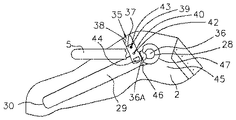
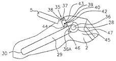
本発明の第二の実施形態の場合には、フォロア13(図22)により、係留地点の海底10の海底面8下に設置された場合動作することができるドラグ・アンカー23(図11、図12、図13)は、アンカー23の対称面X−X内に位置する、長さLの正方形の鋼鉄のプレート錨爪3の上部の平らな面24に直角に溶接されている四辺形の鋼鉄のプレート・シャンク2を備える。シャンク2および錨爪3の厚さの平均は、錨爪3の最大投影面積の平方根の0.04倍を超えない(好適には、0.03倍を超えない)。面24のセンターライン7は、土壌の貫通抵抗を少なくするために、斜めに切断することによって鋭角にされる、錨爪3の縁部25に直角な対称面X−Xの面内に位置する。
In the case of the second embodiment of the present invention, the drag anchor 23 (FIG. 11, FIG. 22) can be operated by the follower 13 (FIG. 22) when installed below the
アンカー・ライン4をシャンク2に接続しているシャックル5に対する負荷作用及び取り付け点26は、錨爪3から遠い方のシャンク2の端部27のところに位置する。センターライン7に沿った面24の重心Cから鋭角な縁部25への方向は順方向Fを形成する。シャックル取付け点26および鋭角な縁部25は、順方向Fに対して、面X−X内に順方向開放角αを形成する対称面X−Xと交差するラインを形成する。重心Cおよびシャックル取付け点26を含む直線は、順方向Fに対して順方向開放角βを形成する。角度αは、柔らかい粘着性の土壌(粘土)内でアンカー23が動作する場合には、95度以上であり、非粘着性の土壌(砂)内で動作する場合には、85度以上である。この場合、角度αは、柔らかい粘土および砂の場合には、それぞれ、100度および90度以上であることが好ましい。角度βは、方向F内で発生する重心Cの変位の、実質的な分力9B(図24)により、アンカー23の係留地点の海底10の土壌内でのアンカー23の移動を妨害することなく、できるだけ90度に近くすることができる。好適には、上記の実質的な分力は、実際の移動方向の変位9Aの35%以上であると見なすことができることが好ましく、50%であれば、さらに好ましい。しかし、実際には、角度β(図11)は、柔らかい粘土内でアンカー23が動作する場合には85度を超えないし、砂地内で動作する場合には70度を超えない。さらに、角度βは、柔らかい粘土内で動作する場合には、68度から85度の範囲内であり、砂地内で動作する場合には50度から65度の範囲内である。さらに好適には、角度βは、柔らかい粘土内で動作する場合には80度を超えないことが好ましいし、砂地内で動作する場合には60度を超えないことが好ましい。
The loading and
シャックル取付け点26(図11)は、シャンク2内の細長い、直線状のスロット29の先端部28により形成される。スロット29の後端部30は、錨爪3の後縁部31に隣接していて、スロット29は、センターライン7に対して、最大30度の順方向開放角γを形成する。好適には、この角度γは10度であることが好ましい。シャンク2の前縁部32は、錨爪3の縁部25に対する土壌貫通抵抗を少なくするために、斜めに切断されて鋭角になっている。重心Cからシャックル取付け点26までの距離は、好適には、0.15L〜0.6Lの範囲内にあることが好ましい。シリンダ状の鋼鉄ピン17(図11−図13)は、設置フォロア13(図22、図23、図24)と係合する場合に、ピボットおよびベアリング・ピンとして機能するように、シャンク・プレート2を横方向に貫通して装着される。ピン17の軸線33は、フォロア13の軸線20のラインが、方向F(図11、図12、図22)とは反対方向に見た場合(アンカー・ライン4が方向Fと平行になるように後に引かれた場合)、アンカー23とシャックル5の面積34(図12)の結合中心を通過するように、面24から間隔をおいて設置されている。これにより、ドラグ・アンカー23を埋設するため、最初に駆動している間、アンカー23の上に加わる合成土壌貫通抵抗力R(図22)は、確実にフォロアの軸線20と同一線上にくる。シャンク2内の、解放することができるシャックル・ストッパ35(図11、図14、図15、図16、図17)は、スロット29の端部28にシャックル5のピン36を保持する。ストッパ35は、スロット29の端部28の後のシャンク2の各側面のところ、および錨爪3から遠い方のスロット29の側面上に一つずつあるアンダーカット凹部38内に、スライドできるように位置している二つの長方形のプレート37を含む。プレート37は、最初、その一部が、凹部38および一部はスロット29内のある位置に位置していて、それにより、シャックル5のピン36が、スロット29の端部28からスライドして遠ざかるのを防止する。凹部38の間のシャンク2内にドリルで開けられた孔部39(図17)は、孔部材39の直径より少し小さい直径を持つ二つの鋼鉄のボール40を含む。鋼鉄のボール40は、圧縮スプリング41により、間隔をおいて保持されている。プレート37は、その内部にドリルで開けられた中央孔部42およびオフセット孔部43を持ち、オフセット孔部43は、ボール40と係合して、凹部38内でプレート37が、スライドすることができる位置を決定する。プレート37は、また、シャンク2の側面45(図17)を越えて突出しているオフセット孔部43から遠い方の端部に取り付けられている直立ブロック44を持つ。シャックル5の各アイ47の内側に突出しているカム46(図14)は、錨爪3の面24に平行な位置から垂直な位置にシャックル5が回転している間に、カム46とブロック44の間で滑り接触が行われるような位置に位置している。それにより、カム46は、ブロック44を押して、プレート37を押し下げてボール40と孔部43との係合を外し、ボール40が孔部42と係合するまでスライドする。その場合、プレート37は、スロット29から完全に外れた状態で保持される(図15)。シャックル5が回転して、カム46をブロック44に接触させた場合、ピン36とプレート37との間の摩擦により、プレート37が、必要なタイミングより早いタイミングで移動するのを防止するために、スロット29内でスライドすることができる、肩付きの回転できないスリーブ36Aをピン36上に設置することができる(図15)。
The shackle attachment point 26 (FIG. 11) is formed by the
その後の、アンカー・ライン4の後方への移動により、カム46がブロック44から外れ、そのため、スリーブ36Aとピン36がスロット29に沿ってスライドすることができるようになり、端部30(図11)のところの位置を変え、それにより、アンカー・ライン4によりアンカー23の低負荷巻き上げが可能になるまで、シャックル5を後方に回転させる。ストッパ35のリセットは、後で、ハンマだけで簡単に行うことができ、各プレート37上のズレにより、ボール40はオフセット孔部43と係合し、そのため、プレート37は、もう一度スロット29内に突出し、シャックル5がスライドして、スロット29の端部28から遠ざかるのを防止する。
Subsequent rearward movement of the
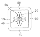
本発明の第三の実施形態の場合には、船舶用アンカーを、係留地点の海底10の表面8の下に直接埋設するためのフォロア部材(図18−図25)は、複数の本体セグメント48を含む、細長い部材13を備える。セグメント48(図19−図21)は、デッキ上で安定するように、幅Wを持ち、断面が正方形になっている。セグメント48は、軸線20を中心にして、軸線方向に対称になっていて、フォロア13の底端部セグメント51に取り付けられているチェーン50を収容するために、そこを通る軸線方向の通路49を備える。通路49の断面は、セグメント48に対して、回転できるようにチェーン50を拘束するために十字形をしている。
In the case of the third embodiment of the present invention, the follower member (FIGS. 18 to 25) for directly embedding a marine anchor under the
各セグメント48(図19)は、セグメント48の端部54のところに、周辺部53から突出している円錐台状の突起52と、反対側の端部57のところの周縁面58内に形成された円錐台状の凹部55を備えているので、セグメント48上の突起52は、隣接するセグメント48内の凹部55とぴったりと適合する。シリンダ状の面58と59が、それぞれ係合するので、隣接するセグメント48は回転することができ、一方、周辺部相互間の接触は維持される(図19−図21)。各セグメント48内の軸線方向の通路49は、フォロア13が、シリンダ状のスタンローラ60を越えて海面63上に位置する、アンカー・ハンドリング船62のデッキ61上に移動した場合、隣接するセグメント48の間の回転によるチェーン50の軸方向の曲がりを最小限度に小さくするために、各端部のところで広くなっている。チェーン50は、各セグメント48(図18、図22−図24)を貫通していて、チェーン50内の張力を保持したり解放したりするための制御セグメントとして機能する上部本体セグメント66も貫通しているチェーン50のリンク65を通るピン64により、底端部セグメント51(図30)に固定されている。
Each segment 48 (FIG. 19) is formed at the
制御セグメント66(図25−図28)は、そこを貫通するチェーン50を収容するための軸線方向の孔部69を含む細長いシリンダ状の栓68を含む軸方向の孔部67を備える。シリンダ状の分割カラー70は、孔部69の全長の内部にピッタリと適合するように、三つのリンク(図27−図28)上にしっかりと固定されていて、また、カラー70および栓68の壁部72を貫通するシャーピン71により、その内部に回転できるように軸線方向に拘束されている。ピン71は、チェーン50を過負荷から保護するために、チェーン50の破壊張力より小さな負荷で、剪断するように機械工作されている。制御セグメント66は、孔部67に貫通している対向側面74内にスロット73を持つ。栓68は、スロット73と係合していて、スライドすることができる、それにボルトで固定されていて、制御セグメント66に対して回転できるように栓68を拘束する働きをする対向キーイング・ブロック75を備える。内部にネジ山を持つスリーブ76は、軸線方向に調整することができ、スリーブ76から遠い傾斜面79を持つネジ山付き固定リング78により、その上に固定することができるように、栓68の壁部72上の外部ネジ77上に係合している。スリーブ76は、制御セグメント66の上面82上にスライドできるように装着されていて、面82から直立しているラグ84に対して反動する圧縮スプリング83により、孔部67内に突出するように駆動される一組の対向ラッチ81を収容する周辺溝80(図27、図28)を持つ。各ラッチ81は、固定リング78上の傾斜面79に接触し、固定リング78が通れるようにし、スリーブ76の溝80内でラッチ81が引続き係合することができるようにするために、スプリング83の力に抗して、ラッチ81を移動させるための下部傾斜面85(図27−図28)を持つ。ラッチ81の位置は、そこから直立しているストッパ・ラグ88により、U字形のヨーク87(図25−図26)の、二つのアーム86により制御される。面82から直立しているラグ90と接している圧縮スプリング89は、アーム86上のストッパ91が、ストッパ・ラグ88と係合し、それにより、アンカー・ハンドリング船62(図18、図26)のスタン・ローラ60またはデッキ61と接触することにより、縁部93と整合状態に保持されていない限り、ヨーク87の外縁部92が、面82(図26)の縁部93を越えて突出するまで、ヨーク87に力を加えて、ラグ90から遠ざかる方向に移動させる。
The control segment 66 (FIGS. 25-28) includes an
ヨーク87のアーム86は、ヨーク87の縁部92が、ローラ60またはデッキ61(図18)と接触することによって、制御セグメント66の縁部93と強制的に整合状態にされた場合、各ラッチ81上の係合傾斜面95を押すための傾斜面94(図25−図26)を持つ。それにより、ラッチ81は、スプリング83を圧縮し、スリーブ76(図28)内の溝80との係合状態から解放される。それ故、栓68は、横方向のスタン・ローラ60上でのフォロア13(図18)の屈曲により、チェーン50内に、望ましくない余分な張力が発生するのを防止するために、孔部67に沿って距離W/4を自由にスライドすることができる。
The
栓68上のスリーブ76の軸線方向の位置は、フォロア13全体が、ローラ60の下に吊り下がった場合、フォロア13の浮力重量が、ラッチ81を栓68上の溝80と係合させるのに丁度十分な長さだけチェーン50を延ばすように、リング78により調整し固定することができる。これにより、チェーン50内の張力が緩むのが防止される。何故なら、貫通している間、フォロア13の重量が、海底の土壌により次第に支持されるからである。それ故、フォロア13のセグメント間の把持力が、次第に増大して、その結果、貫通を完了する前に、フォロア13が、座屈するのを防止する剛性が発生する。
The axial position of the
それ故、フォロア13は、ライン16により垂直に吊り下げられた場合、上記の硬質フォロアとほぼ同じ働きをするが、スタン・ローラ60を横切っている間、損傷を起こさないで復元できるように曲がることができる。
Therefore, the
本出願人の英国特許第2,199,005号(UK PatentNo.2,199,005)および米国特許第4,864,955号(US Patent No.4,864,955)が開示しているように、直線状の縁部98を備えるカージオイド・カム(cardioid cam)97を持つ位置決めリンク96(図18、図29)は、制御セグメント66内に栓68から間隔をおいて位置する。チェーン50は、リンク96上の後部クレビス100にピン99を通して接続している。上記クレビス18は、45度の角度で縁部98の方向に傾斜している。リンク96は、シャックル101を通してアンカーを海中に沈めたり引き上げたりするためのライン16に接続している。このアンカーを海中に沈めたり引き上げたりするためのライン16は、アンカー・ハンドリング船62(図18)のデッキ61上の第一ウィンチ102により繰り出され、巻き上げられる。リンク96は、直線状の縁部98が、ローラ60に完全に接触した場合だけ、安定した方向を向いてローラ60上に位置することができ、この安定した方向が確立されるまで、カージオイド・カム97を中心にして転倒する。それ故、リンク96は、チェーン50のリンクを、ある回転方向を向いてローラ60に対して強制的に45度で跨らせるために使用される。上記回転方向により、その内部のカラー70およびブロック75を通して制御セグメント66と連通した場合であって、制御セグメント66がその上に巻き上げられた場合、ヨーク87はローラ60に接触する。
Applicant's UK Patent No. 2,199,005 (UK Patent No. 2,199,005) and US Pat. No. 4,864,955 (US Patent No. 4,864,955) are disclosed. In addition, a positioning link 96 (FIGS. 18, 29) having a
フォロア13の底端部セグメント51は、すでに説明したように、ドラグ・アンカー23に取り外すことができるように接続することができ、各クレビス脚部105内の凹状のソケット104が、シャンク2上のピボット・ピン17を収容し、それと係合することができるようにするために、アンカー23の跨りシャンク2用の細長いクレビス103(図22−図23)を含む。各クレビス脚部105上のラグ106は、シャンク2内の孔部108と同一平面上に位置する、ドリルで開けられた貫通孔107を持ち、順方向Fが軸20と平行で、ピン17がソケット104内に係合している状態で、底端部セグメント51のクレビス103内に、アンカー23を一時的に保持する固定シャーピン109を収容する。クレビス103の脚部105上のストッパ21は、錨爪3と接触することにより、必要な度数にピン17を中心にしてアンカー23の回転を制限する。パイル13の長さより約5%長いアンカー・フォーランナー・ライン(anchor fore−runner line)4Aは、アンカー23のシャックル5の一方の端部に取り付けられ、他方の端部において、アンカー・ライン4に接続するために、ヒンジ・リンク110に接続している。ヒンジ・リンク110は、突出ヒンジ・ピン110Aと係合している。二つの平行なフック111は、間に間隔をおいて、ヨーク87から遠い方の制御セグメント66の面74上に装着される。各フック111は、ヒンジ・ピン110Aの突出端部と係合するための支持体として機能し、それにより、アンカー・ライン4上に、垂直線からの角度が60度未満の力が上方に加わった場合、ヒンジ・リンク110が、フック111から外れるように、制御セグメント66に取り外すことができるように取り付けることができる。このような取り外し可能な接続により、シャックル・ストッパ35を丁度いいタイミングより早い時点で解放することなく、フック111を引っ張っているアンカー・ライン4による設置作業中に、アンカー23の方位角の方向を制御することができ、それにより、依然としてフック111から容易にリンク110を取り外すことができ、その後で、アンカー・ライン4を引き上げることができる。
The
停泊中に組み立てる場合には、フォロア13およびドラグ・アンカー23のすべての部材は、アンカー・ハンドリング船62(図18)のデッキ61上に広げられるが、その場合、制御セグメント66上のヨーク87(図25−図26)は、デッキ61と接触している。ドラグ・アンカー23は、ソケット104内に係合しているピン17により底端部セグメント51に取り付けられ、固定シャーピン109は、整合孔部107および108を通して取り付けられる。カラー70(図27)は、チェーン50の底端部から必要な距離のところで、チェーン50の三本のリンクに固定される。栓68は、カラー70上をスライドし、ピン71によりそこに固定される。その後で、チェーン50は、栓68が孔部67(図27)の遠い方の端部と接触するまで、制御セグメント66およびセグメント48を通して引かれる。チェーン50は、チェーン端部のリンク65を、ピン64(図30)により底端部セグメント51内に固定できるように、制御セグメント66から十分離れているセグメント48から突出している。油圧チェーン・ジャッキは、チェーン50を引張り、その後で、フォロア13のセグメントを一体状態に圧縮するために制御セグメント66上に装着されている。チェーン・ジャッキが供給するチェーン50内の張力は、フォロア13およびドラグ・アンカー23の海中での浮力重量の合計と等しくなるように設定される。これにより、栓68のスリーブ76上の溝80(図27)が、制御セグメント66上で、ラッチ81を対向方向に引くまでチェーン50は延びる。その後で、スリーブ76は、チェーン50内の負荷が、フォロア13およびドラグ・アンカー23の、海中浮力重量の合計に等しくなる寸前にラッチ81が溝80に係合することができるように、ネジ山77上を回転し、リング78によりその上に固定される。その後で、チェーン・ジャッキが除去され、位置決めリンク96は、位置決めリンク96がローラ60(図29)と接触している状態で、そこから吊り下がった場合、フォロア13がローラ60から離脱して回転できるように、栓68から十分離れたところで、ライン16とチェーン50の間に位置決めリンク96を取り付ける。アンカー・フォーランナー・ライン4Aは、アンカー23上でシャックル5と接続し、制御セグメント62上のフック111内で係合するヒンジ・リンク110に接続する。これで、アンカー・ハンドリング船62上での組立は完了する。アンカー・ライン4は、海中に設置される前に、補助アンカー・ライン運搬船上のウィンチ上にスプールされる。
When assembled during berthing, all members of
海上においては、アンカー・ハンドリング船62およびアンカー・ライン運搬船が、設置場所へ移動する。パイル13の制御セグメント66のフック111上に係合しているヒンジ・リンク110に接続するために、アンカー・ライン4の一方の端部が船62の上を通される。その後で、アンカー・ライン4は、パイル13およびアンカー23の方向を制御するために、両方の船の間の湾曲に緩んだ状態で垂れ下がる。アンカー・ライン運搬船66上においては、引張ウィンチ・ラインが、スタン・ローラ60に隣接して固定されているプーリ・ブロックを通して制御セグメント66に取り付けられ、デッキ61上を船尾方向に制御セグメント66を引くように動作するので、スタン・ローラ60を通して、船外に、ドラグ・アンカー23およびフォロア13を押す。船外に突出している底端部セグメント51とドラグ・アンカー23の重量により、フォロア13は、ローラ60上で90度曲がる。制御セグメント66内の孔部67に沿って軸方向に栓68が距離W/4だけ移動するので、チェーン50内の結果としての過度の張力の発生が防止される。それ故、フォロア13は90度曲がり、一方、チェーン50内の張力により、横方向ローラ60は、ドラグ・アンカー23およびフォロア13の、海中浮力重量の合計に等しい最大値に上昇するだけである。セグメント48の十分な重量が船外に移動し、フォロア13は、ウィンチ102がライン16を繰り出し、フォロア13およびドラグ・アンカー23を下の係留地点の海底10の表面8に最終的に接地させると、上記ウィンチ102が供給する制動拘束力により自ら海中に沈んでいく。アンカー・ライン運搬船は、アンカー・ハンドリング船62が繰り出しているアンカー・ライン16と歩調を揃えてアンカー・ライン4を繰り出し、アンカー23が海底の土壌10内に埋没するまで、フォロア13およびアンカー23の方位角方向を制御するためにライン4内の張力を十分な大きさに維持する。
At sea, the
ドラグ・アンカー23およびフォロア13の海中の重量により、チェーン50内に発生した張力は、チェーン50を延ばし、栓68上の溝80が、制御セグメント66がローラ60から離脱した場合に、ヨーク87のスプリングによる移動によりすでに解放されているスプリング・ラッチ81と係合することができるようにする。ラッチ81により、チェーン50が収縮するのが防止され、それにより、チェーン50内に重量により発生した張力を維持するように機能する。
The tension generated in the
ドラグ・アンカー23は、ライン16および4が繰り出されると、アンカー23およびフォロア13の浮力重量の合計により、強制的に係留地点の海底面8から土壌10(図27)内に埋設される。都合のよいことに、ライン16は、例えば、ドラグ・アンカー23が海底面8を滑らかに貫通するのを容易にするために、アンカー・ハンドリング船62の巻上げ動作の伸縮可能な吸収装置として機能する弾性ナイロン部分を含むことができる。フォロア13のセグメントは、ラッチ81によりチェーン50内に維持されている張力で一体に固定されていて、その結果、フォロア13が剛性パイルであるかのような働きをする。
When the
アンカー23の海底への貫通の完了は、アンカー・ハンドリング船62上のウィンチ102上の負荷セルにより信号で知らされ、アンカー23およびフォロア13が、海底の土壌により完全に支持された場合、ライン16の海中の重量まで低減するライン16内の張力により表示される。その後で、ライン16は、繰り出されて緩み、アンカー・ハンドリング船62は、フォロア13の位置を通過して移動することができる。アンカー・ライン運搬船は、フォロア13の真上の位置に移動し、アンカー・ライン4を引き上げ、その結果、ヒンジ・リンク110は、フォロア13上のフック111から離脱し、ライン4がピンと張る。ピンと張ったライン4上にマークがつけられ、上記マークが、フォロア13の二つのセグメント48の長さにほぼ等しい距離を移動するまで、ライン4は再び海中に繰り出される。これにより、アンカー23およびフォロア13は、一緒に海底の土壌10から上方に移動し、同時に、シャーピン109を分離させ、錨爪3を垂直線から傾斜させるために、ソケット104(図22−図23)内でピン17を中心にしてアンカー23を回転する。次に、アンカー・ライン4が繰り出され、それにより、フォロア13が海中の重量により、アンカー23を錨爪3(図23)の現在の傾斜している方向Fに向けて下方に駆動させることができる。ライン4が引き上げられると、フォロア13の海中の重量とアンカー・ライン4内の張力との間に強力な結合が生まれる。その後で、ライン4が繰り出されると、フォロア13の海中の重量とアンカー23に作用しているオフセット土壌抵抗力Rとの間に強力な結合が生まれる。両方の結合は、アンカー23の必要な回転を増大するように作用する。このシーケンスは、数回反復して行われる。ストッパ21が、錨爪3(図23)と接触するまで、回転の度にアンカー23の錨爪は垂直線から離れてゆく。この回転プロセスは、キーイング(keying)とも呼ばれ、設置フォロア13を除去した後で負荷が掛かっている直接エンベッドメント・アンカー11(図8)のところですでに説明したように、錨爪3の重心Cを、距離kを通して、海底面8の下の貫通深さを浅くしないで行われる。
The completion of
アンカー・ライン4は、現在、繰り出されて緩んでいて、そのため、アンカー・ハンドリング船62がフォロア13の真上に移動することができるように、アンカー・ライン運搬船は遠ざかる方向に移動することができ、その結果、ウィンチ102は、ライン16を引き上げ、フォロア13をアンカー23切り離し、係留地点の海底10から引き離してスタン・ローラ60のところまで引き上げることができる。制御セグメント66がローラ60と接触すると、ヨーク87が、スプリング89に対して押され、強制的にラッチ81をスプリング83に押し付け、栓68内の溝80から離脱させる。それ故、栓68は、解放され、ローラ60を上下動した場合に、チェーン50内に望ましくない余分な張力を発生しないで、フォロア13が90度曲がることができるように、孔部67に沿ってW/4にほぼ等しい距離を移動する。ウィンチ102による繰り出しは、フォロア13全体がデッキ61上に引き上げられた時に停止する。
その後で、アンカー・ハンドリング船62は前進して、海底上に固定される対象物の係留地点の水平方に適当な角度で、アンカー・ライン4を土壌10(図24)内に引く。それによるシャックル5の移動により、シャックル・アイ47の上の栓46(図14−図16)は、ストッパ35のプレート37を押し、アンカー23の後で容易に巻き上げることができるように、アンカー23のシャンク2上の解放位置に移動させる。その後で、固定対象物の方向から遠ざかるように、アンカー・ライン4を引くことにより、シャックル5が、スロット29を端部30(図11)までスライドし、それにより、巻上げ作業中に、アンカー23を回収するための低い抵抗を実現することができる。
Thereafter, the
すでに説明した直接固定ドラグ・エンベッドメント・アンカー1の場合には、直接固定したドラグ・アンカー23は、目標の埋設深さのところで供給することができる容量以上の負荷を掛けられた場合には、下向きの湾曲した軌跡9を辿る。それ故、アンカー23は、過負荷に見合うように容量を増大する。最終的には、従来のドラグ・エンベッドメント・アンカーの場合には、ドラグ・アンカー23は、係留地点の海底10の表面8の下の限界深さに到着し、その深さで最大容量となるが、壊滅的な損傷は起こらない。何故なら、アンカーの現在の移動は水平方向であるからであり、その結果、ドラグ・エンベッドメント・アンカーに対する通常の安全係数1.5を使用することができるからである。
In the case of the directly fixed
都合のよいことに、アンカー23およびフォロア13は、船舶用アンカーおよび直接エンベッドメント・アンカーの外面に潤滑油のフィルムを供給するための装置を開示している、本出願人の同時係属国際特許出願PCT/GB98/01089(公開番号WO98/49048)の特許を援用することができる。図30−図33について説明すると、フォロア13の制御セグメント51は、すでに説明したように、チェーン50に取り付けられている。セグメント51の上部51Aは、軸線方向のシリンダ上の凹部112と、ピストン・ロッド114に取り付けられている環状ピストン113を含む。環状ピストン113およびピストン・ロッド114は、細長い固定ピストン116を収容する細長いシリンダ状凹部115を含む。ピストン116の頂端部は、凹部112内のセグメント51の上部51Aに取り付けられている。環状ピストン113は、上部51Aの凹部の壁部119内の、内部溝118内をスライドすることができるキー117により、上部51Aに回転できるように固定されている。ピストン・リング・シール120は、固定ピストン116の底端部に取り付けられている。取り外すことができる固定キャップ121は、セグメント51の一部を形成していて、とりわけ、凹部112内にピストン113を保持し、ピストン・ロード114を密封するためのリング・シール122を収容する働きをする。それ故、セグメント51は、ピストン116を囲む上部環状凹部123と、ピストン・ロッド114内の下部シリンダ状凹部115を含む。セグメント51内においては、逆止め弁124および通路125により、凹部123を適当な潤滑油により満たすことができ、逆止め弁126、および固定ピストン116を通る通路127により、凹部115を潤滑油で満たすことができる。この場合、ピストン・ロッド114は、保持キャップ121から最大限延びた状態になる。
Conveniently, the
ピストン113は、ピストン113を通過した潤滑油を保持キャップ121内の円周方向の通路129内に導く働きをする軸線20に平行な周辺通路128を持つ。通路129と連絡している複数の孔部130は、潤滑油を保持キャップ121の外面に均等に供給するための外部出口孔部としての働きをする保持キャップ121の周囲に沿って等間隔で配置されている。ピストン・ロッド114は、クレビス・ラグ105(図30)を持つクレビス103を含む。通路131は、ピストン17が、クレビス103(図30)のソケット104内で係合した場合に、アンカー23のピン17内に、軸方向を向いて位置する通路132と合って、この通路と結合するように、ピストン・ロッド114内の凹部115から各脚部に沿ってクレビス103のソケット104に連絡している。リング・シール133(図31)は、ピン17とソケット104内のクレビス103との間にスライドすることができ、また離脱することができる回転シーリングを供給する。通路134(図30−図32)は、アンカー23のシャンク2内を、ピン17内の通路132から、シャンク2の鋭角の縁部32、および錨爪3の鋭角の縁部25に平行に走り、これらの縁部と連絡している通路135(図30、図33)に連絡している。孔部136は、シャンク2の外面およびアンカー23の錨爪3の外面に、潤滑油を均等に供給する目的で、通路135(図30、図33)に対して外部出口孔部を設けるために、縁部25および32に沿って等間隔で配置されている。
The
使用中、クレビス115および123は、逆止め弁126および124により、それぞれ、生分解可能な植物性グリース(biodegradable vegetable grease lubricant)137で満たされる。アンカー23が、すでに説明したように、係留地点の海底10の表面8を貫通すると、土壌抵抗力R(図22)は、強制的に、ピストン113および116(図30)に、凹部115および123内の潤滑油137を加圧させ、アンカー23およびフォロア13が、その合成海中重量により係留地点の海底の土壌10内に押し込まれた場合、強制的に、潤滑油を通路128、131、132、134および135に沿って、また孔部130および136から排出させる。凹部115を凹部123から分離することにより、確実に、ピストン・ロッド114の単位移動(unit movement)により、アンカー23から排出される量に対して、フォロア13から排出される潤滑油の量の所望の割当てを達成することができる。排出された潤滑油137は、アンカー23およびフォロア13の外面上を通る土壌10内に混入し、これらの面への土壌の付着力を大幅に低下させる。それ故、土壌の付着力によるアンカー23およびフォロア13の外面上の実効表面摩擦力は、係留地点の海底10内への貫通を同時に望ましい方法で促進することにより、かなり大幅に低減され、係留地点の海底10からフォロア13を回収する場合、低い巻上げ負荷の以降の促進をかなり有意に低減する。フォロア13がアンカー23から離脱すると、潤滑油の供給が停止する。軌跡9に沿ったアンカー23の以降の移動により、すべての残留潤滑油が拭き取られ、そのため、アンカー23上の摩擦制限が回復し、すでに説明したように、ドラグ・アンカーとして機能することができる。
During use,
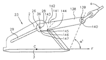
アンカー23は、さらに、一方の端部140にアンカー・ライン取付け孔部139を持ち、他方の端部に、シャンク2を跨いでいて、直線状のスロット29内で摺動可能でかつ回転可能に係合するために、ピン36を担持するクレビス141を持っていて、シャンク2に取り付けられているシャックルの代わりに、細長いプレート部材138(図34)を持つことができる。シャンク2は、スロット29の先端部28のところに、取付け点26の中心を持つアーチ状の面143を持つ。クレビス141内のストッパ144は、面143とスライド接触し、それにより、点26を中心とする部材138の回転により、ストッパ144の移動方向が、スロット29と平行になり、ピン36がスロット29内を自由にスライドすることができるようになるまでピン36を点26に保持する。回転停止シャーピン145は、クレビス141内の孔部146内、およびシャンク2内の整合孔部147内に装着されていて、細長いプレート部材138を、角度α’が95度未満、好適には75度未満である所望の位置に保持する働きをする。シャーピン145は、アンカー・ライン4から孔部139に掛かった負荷が、ある値を超えた場合に、分離するような大きさになっている。これにより、アンカー23は、最初、シャーピン145が分離する前は、ドラグ・エンベッドメント・アンカーとして機能し、その後で、さらに海底を移動した場合には、非常に増大した保持容量を持つドラグ・アンカーとして機能することができる。
The
重量9キロのドラグ・アンカー23(図22−図24)、および重量126キロのフォロア13に対して、若干固めた柔らかい粘土の海底10内で試験を行った。上記すべての機構および手順は計画通り機能した。アンカー23の重心C(図24)を、フォロア13により、海底面8の下の錨爪3の面積の平方根の3倍の深さに設置した状態で、アンカー・ライン4を、海底面8のところで、水平方向に対して18度の傾斜角で引いた場合、アンカー23は、(海底10からフォロア13を回収した直後に)53倍のアンカー重量の保持容量を備えた。さらに、アンカー・ライン4を引くと、アンカー23は移動したが、その場合、埋設の深さは深くなり、保持容量は次第に増大し、最終的にはアンカー重量の189倍で一定になり、その場合、重心Cは水平方向に移動し、アンカー・ライン4は水平方向に対して23度傾斜した。潤滑油137(図30)を使用して、また使用しないで試験を行ったが、試験結果は、潤滑油を使用した場合には、錨爪3の重心Cの貫通力は3.2倍増大し、潤滑油を使用した場合と同じ貫通を行うには、潤滑油を使用しない場合には、フォロア13の重量をほぼ3倍にする必要があることを示した。アンカー23の錨爪3上の重心Cが、フォロア13により、海底面8の下、錨爪3の面積の平方根の1.1倍の深さに埋設された、潤滑油を使用しない試験の場合には、アンカー23は保持容量が次第に減少し、その設置位置から移動した場合、海底面8までアンカー23が上昇した。これらの試験は、ドラグ・アンカー23の潤滑油を使用するフォロアによる設置の有効性、およびアンカー23の角度αおよびβ(図11)に対する上記ダンフォースの制限により制約を受けないことを証明した。
Tests were conducted in a slightly softened
本明細書は、本発明の特定の実施形態を記載しているが、上記の概略の試験結果は、本発明の目的が達成されたことを示す。これらの実施形態の変更は、本発明の範囲内に含まれることは明らかであろう。例えば、非常に長く延ばすことができる合成ロープを、チェーン50の代わりに、フォロア13内で使用することができ、その場合、制御セグメント66の張力解放機構を使用しないですむ。
While this specification describes particular embodiments of the present invention, the above summary test results indicate that the objectives of the present invention have been achieved. It will be apparent that modifications to these embodiments are included within the scope of the present invention. For example, a synthetic rope that can be extended very long can be used in the
Claims (21)
(a) 請求項1から8のいずれか一項に記載の船舶用アンカー(23)を備え、
(b) 該アンカー(23)を前記係留地点の海底の第一の埋設位置に固定し、
(c) 前記第一の埋設位置において、前記錨爪部材の重心(C)は該錨爪部材の前記の一方の側で、前記錨爪部材の最大投影面積の平方根の少なくとも2倍の深さのところにあり、
(d) 前記アンカー(23)が前記第一の埋設位置にある時、アンカーライン取り付け手段(5)に取り付けられたアンカーライン(4)によって前記アンカー(23)に引っ張り力を加えて、前記順方向Fの方向の変位の実質的な分力(9B)により、前記アンカー(23)が、前記係留地点の海底(10)の土壌内で移動しようとするようになっている、各ステップを備えていることを特徴とする船舶用アンカー(23)を係留地点の海底(10)に固定する方法。 A method of securing a marine anchor (23) to a seabed (10) at a mooring point, the method comprising:
(A) The marine anchor (23) according to any one of claims 1 to 8,
(B) fixing the anchor (23) at a first buried position on the seabed of the mooring point;
(C) In the first embedding position, the center of gravity (C) of the claw member has a depth at least twice the square root of the maximum projection area of the claw member on the one side of the claw member. And
(D) When the anchor (23) is in the first embedding position, a tensile force is applied to the anchor (23) by the anchor line (4) attached to the anchor line attaching means (5), and the order Each step is such that the substantial force (9B) of displacement in direction F causes the anchor (23) to move within the soil at the seabed (10) at the mooring point. A method of fixing a marine anchor (23) to a seabed (10) at a mooring point, characterized in that
(e) 前記アンカー(23)を第二の埋設位置に前記第一の埋設位置より深く埋設し、
(f) 前記アンカーライン取り付け手段(5)を前記細長いスロット(29)に沿って前記後端部(30)へ滑動させ前記アンカーライン(4)上に引っ張ることによって、前記アンカー(23)を前記順方向Fに対しほぼ反対方向に、後方へ回収する、ステップを含むことを特徴とする方法。 15. A method according to any one of claims 9 to 14, wherein the method further comprises:
(E) burying the anchor (23) deeper than the first burying position in the second burying position;
(F) sliding the anchor line attachment means (5) along the elongated slot (29) to the rear end (30) and pulling on the anchor line (4), thereby Recovering backwards in a direction substantially opposite to the forward direction F.
Applications Claiming Priority (4)
| Application Number | Priority Date | Filing Date | Title |
|---|---|---|---|
| GB9825363.6 | 1998-10-30 | ||
| GBGB9825363.6A GB9825363D0 (en) | 1998-10-30 | 1998-10-30 | Improvements in marine anchors |
| GB9824006.2 | 1998-11-04 | ||
| GBGB9824006.2A GB9824006D0 (en) | 1998-11-04 | 1998-11-04 | Improvements in marine anchors |
Related Parent Applications (1)
| Application Number | Title | Priority Date | Filing Date |
|---|---|---|---|
| JP2000579482A Division JP2003516890A (en) | 1998-10-30 | 1999-10-29 | Improvement of ship anchor |
Publications (2)
| Publication Number | Publication Date |
|---|---|
| JP2010089782A true JP2010089782A (en) | 2010-04-22 |
| JP5095710B2 JP5095710B2 (en) | 2012-12-12 |
Family
ID=26314596
Family Applications (2)
| Application Number | Title | Priority Date | Filing Date |
|---|---|---|---|
| JP2000579482A Pending JP2003516890A (en) | 1998-10-30 | 1999-10-29 | Improvement of ship anchor |
| JP2009272095A Expired - Fee Related JP5095710B2 (en) | 1998-10-30 | 2009-11-30 | Improvement of marine anchor |
Family Applications Before (1)
| Application Number | Title | Priority Date | Filing Date |
|---|---|---|---|
| JP2000579482A Pending JP2003516890A (en) | 1998-10-30 | 1999-10-29 | Improvement of ship anchor |
Country Status (23)
| Country | Link |
|---|---|
| US (1) | US6598555B1 (en) |
| EP (3) | EP1462356B1 (en) |
| JP (2) | JP2003516890A (en) |
| CN (2) | CN1137833C (en) |
| AP (1) | AP1415A (en) |
| AR (1) | AR021046A1 (en) |
| AT (2) | ATE363428T1 (en) |
| AU (1) | AU761296B2 (en) |
| BR (1) | BR9915202A (en) |
| CA (1) | CA2348078C (en) |
| CU (1) | CU23114A3 (en) |
| DE (2) | DE69936231T2 (en) |
| DK (1) | DK176066B1 (en) |
| ES (2) | ES2288206T3 (en) |
| HK (1) | HK1056709A1 (en) |
| ID (1) | ID28960A (en) |
| IS (1) | IS5926A (en) |
| NO (1) | NO333123B1 (en) |
| NZ (1) | NZ511324A (en) |
| OA (1) | OA11794A (en) |
| PT (2) | PT1321356E (en) |
| SG (1) | SG110039A1 (en) |
| WO (1) | WO2000026081A2 (en) |
Cited By (1)
| Publication number | Priority date | Publication date | Assignee | Title |
|---|---|---|---|---|
| KR101734366B1 (en) | 2016-01-26 | 2017-05-12 | 조재정 | Anchor with a hydraulic cylinder |
Families Citing this family (35)
| Publication number | Priority date | Publication date | Assignee | Title |
|---|---|---|---|---|
| CN101624086B (en) * | 2009-08-04 | 2011-08-10 | 天津大学 | Vertically loaded anchor (VLA) dragging-mooring switching mechanism |
| GB201006362D0 (en) * | 2010-04-16 | 2010-06-02 | Brupat Ltd | Offshore marine anchor |
| JP2013532091A (en) | 2010-05-28 | 2013-08-15 | ロッキード マーティン コーポレイション | Subsea anchoring system and method |
| NO331792B1 (en) | 2010-08-10 | 2012-04-02 | Deep Sea Anchors As | A gravity-installed anchor and procedure for installing the anchor |
| GB201018670D0 (en) * | 2010-11-05 | 2010-12-22 | Brupat Ltd | Anchor data communicaiton system |
| GB201105372D0 (en) | 2011-03-30 | 2011-05-11 | Inst Of Technology Sligo | An anchor assembly |
| GB201117570D0 (en) * | 2011-10-12 | 2011-11-23 | Brupat Ltd | Improved offshore marine anchor |
| US20130125805A1 (en) * | 2011-11-09 | 2013-05-23 | Manson Anchors Limited | Anchor system |
| CN102556284B (en) * | 2012-03-02 | 2014-04-16 | 中国石油大学(华东) | Suction penetrating arc-shaped plate anchor, mounting tool for same and construction method for same |
| CN102602506B (en) * | 2012-03-27 | 2014-06-18 | 上海交通大学 | Separable self-drilling embedment anchor |
| US9469960B2 (en) * | 2012-09-20 | 2016-10-18 | Intermoor Inc. | Method of and apparatus for installation of plate anchors |
| US9422034B2 (en) | 2014-03-27 | 2016-08-23 | Intermoor Inc. | Actively steerable gravity embedded anchor systems and methods for using the same |
| CN104266041B (en) * | 2014-09-25 | 2023-04-18 | 江南工业集团有限公司 | Underwater bottom-sinking fixing device |
| CN104452758B (en) * | 2014-11-06 | 2016-03-02 | 河海大学 | A kind of drop-down rotation anchor device of suction penetrated and construction method thereof |
| CN104590490B (en) * | 2014-12-16 | 2017-08-25 | 福建省水产研究所 | Embedded seabed formula mooring system |
| KR101557361B1 (en) * | 2015-06-17 | 2015-10-08 | (주)아진이엔지 | the rotation type hybrid anchor block |
| CN105416510B (en) * | 2015-12-01 | 2017-06-20 | 江苏科技大学 | A kind of bionical high holding power anchor |
| CN105644720B (en) * | 2016-03-25 | 2017-06-23 | 中国石油大学(华东) | Modified torpedo anchor |
| CN106240748B (en) * | 2016-08-09 | 2018-01-23 | 大连理工大学 | For increasing the heavy method and its propeller for passing through depth of dynamic anchor |
| CN107640287A (en) * | 2017-09-29 | 2018-01-30 | 夏尔特拉(北京)太阳能科技有限公司 | Hammer entering-in-mud type plate anchor and its installation tool and enter mud construction method |
| WO2019083996A1 (en) * | 2017-10-23 | 2019-05-02 | Marine Technologies, Llc | Towboat and operations thereof |
| CA3092877A1 (en) * | 2018-03-23 | 2019-09-26 | Cashman Dredging And Marine Contracting, Co., Llc | Anchor driving device |
| WO2019218115A1 (en) * | 2018-05-14 | 2019-11-21 | 大连理工大学 | New lightweight dynamic mounting anchor and mounting method |
| CN108423125B (en) * | 2018-05-14 | 2023-11-24 | 大连理工大学 | Novel light power installation anchor and installation method |
| CN108725701A (en) * | 2018-06-29 | 2018-11-02 | 合肥学院 | A kind of separable torpedo anchor of anchor body |
| KR102187626B1 (en) * | 2019-07-02 | 2020-12-07 | 주식회사 예성오션테크 | Drilling apparatus |
| CN111301610B (en) * | 2020-02-17 | 2021-08-20 | 大连理工大学 | Combined power anchor of folding anchor shank and verticality control method thereof during underwater falling |
| US11827314B2 (en) * | 2020-02-17 | 2023-11-28 | Dalian University Of Technology | Hybrid dynamically installed anchor with a folding shank and control method for keep anchor verticality during free fall in water |
| CN112612220B (en) * | 2020-10-24 | 2021-12-03 | 北京博瑞知天科技有限责任公司 | Instruction analysis system based on target identification |
| CN114132434B (en) * | 2021-11-25 | 2023-02-10 | 江苏航运职业技术学院 | Mooring equipment for fixing ship in shore and using method |
| CN114232687B (en) * | 2021-11-30 | 2023-08-11 | 温州大学 | Separation strutting arrangement suitable for suspension tunnel anchor rope |
| CN114572345B (en) * | 2022-03-04 | 2024-01-23 | 中国舰船研究设计中心 | Sliding anchor device and use method thereof |
| CN114771730B (en) * | 2022-04-15 | 2023-05-12 | 中国船舶科学研究中心 | Quick anchor rack arranging device and method suitable for small-freeboard ship anchors |
| CN114750874B (en) * | 2022-05-06 | 2023-03-14 | 中铁大桥勘测设计院集团有限公司 | Anchoring method of interlinked anchor device |
| NL2032466B1 (en) * | 2022-07-12 | 2024-01-25 | Itrec Bv | Installation follower for installing plate anchors for floating wind turbines of a wind farm |
Citations (2)
| Publication number | Priority date | Publication date | Assignee | Title |
|---|---|---|---|---|
| JPS5644997U (en) * | 1979-09-17 | 1981-04-22 | ||
| JPH0561411B2 (en) * | 1984-05-11 | 1993-09-06 | Inst Francais Du Petrole |
Family Cites Families (14)
| Publication number | Priority date | Publication date | Assignee | Title |
|---|---|---|---|---|
| GB553235A (en) | 1941-03-12 | 1943-05-13 | Richard Stevens Danforth | Anchors |
| US2674969A (en) | 1952-12-04 | 1954-04-13 | Robert H Eckhoff | Mooring anchor |
| US3194204A (en) * | 1963-02-01 | 1965-07-13 | Donald A Nichols | Towing cable with fairings |
| US4312289A (en) * | 1979-11-13 | 1982-01-26 | Joseph Conrad | Permanent mooring apparatus |
| US4397255A (en) * | 1981-06-15 | 1983-08-09 | The United States Of America As Represented By The Secretary Of The Navy | Anchor holding capacity augmentation system |
| DE3338137A1 (en) * | 1983-10-20 | 1985-05-09 | Hochtief AG, 4300 Essen | Pile-foundation method for drilling and/or production platforms, as well as an apparatus for carrying out the same |
| US4542708A (en) * | 1984-01-06 | 1985-09-24 | Raytheon Company | Composite cable fairing |
| US4619218A (en) * | 1984-01-30 | 1986-10-28 | Hen-Jac, Inc. | Embedment anchor |
| GB8613485D0 (en) | 1986-06-04 | 1986-07-09 | Brupat Ltd | Anchor orientation device |
| WO1993003958A2 (en) * | 1991-08-16 | 1993-03-04 | Vrijhof Ankers Beheer B.V. | Anchor, anchorfluke and methods for anchoring |
| GB9125241D0 (en) * | 1991-11-27 | 1992-01-29 | Brupat Ltd | Drag embedment marine anchor |
| NL192121C (en) * | 1993-09-22 | 1997-02-04 | Waal Technology & Consultancy | Drop block. |
| GB9701285D0 (en) * | 1997-01-22 | 1997-03-12 | Brupat Ltd | Marine anchor |
| GB9708699D0 (en) | 1997-04-30 | 1997-06-18 | Brupat Ltd | Improvements in marine anchors |
-
1999
- 1999-10-29 PT PT03075742T patent/PT1321356E/en unknown
- 1999-10-29 CN CNB99812964XA patent/CN1137833C/en not_active Expired - Fee Related
- 1999-10-29 OA OA1200100101A patent/OA11794A/en unknown
- 1999-10-29 AT AT03075742T patent/ATE363428T1/en not_active IP Right Cessation
- 1999-10-29 US US09/806,508 patent/US6598555B1/en not_active Expired - Lifetime
- 1999-10-29 DE DE69936231T patent/DE69936231T2/en not_active Expired - Lifetime
- 1999-10-29 CN CNB031078826A patent/CN1264722C/en not_active Expired - Fee Related
- 1999-10-29 EP EP04076414A patent/EP1462356B1/en not_active Expired - Lifetime
- 1999-10-29 CA CA002348078A patent/CA2348078C/en not_active Expired - Fee Related
- 1999-10-29 AT AT04076414T patent/ATE391666T1/en not_active IP Right Cessation
- 1999-10-29 BR BR9915202-9A patent/BR9915202A/en not_active IP Right Cessation
- 1999-10-29 NZ NZ511324A patent/NZ511324A/en not_active IP Right Cessation
- 1999-10-29 AU AU10546/00A patent/AU761296B2/en not_active Ceased
- 1999-10-29 AP APAP/P/2001/002126A patent/AP1415A/en active
- 1999-10-29 ES ES03075742T patent/ES2288206T3/en not_active Expired - Lifetime
- 1999-10-29 JP JP2000579482A patent/JP2003516890A/en active Pending
- 1999-10-29 EP EP99954102A patent/EP1124718A2/en not_active Withdrawn
- 1999-10-29 ID IDW00200101159A patent/ID28960A/en unknown
- 1999-10-29 EP EP03075742A patent/EP1321356B1/en not_active Expired - Lifetime
- 1999-10-29 PT PT04076414T patent/PT1462356E/en unknown
- 1999-10-29 DE DE69938515T patent/DE69938515D1/en not_active Expired - Lifetime
- 1999-10-29 ES ES04076414T patent/ES2305655T3/en not_active Expired - Lifetime
- 1999-10-29 WO PCT/GB1999/003587 patent/WO2000026081A2/en not_active Application Discontinuation
- 1999-10-29 SG SG200301955A patent/SG110039A1/en unknown
- 1999-11-01 AR ARP990105513A patent/AR021046A1/en not_active Application Discontinuation
-
2001
- 2001-04-19 NO NO20011949A patent/NO333123B1/en not_active IP Right Cessation
- 2001-04-24 IS IS5926A patent/IS5926A/en unknown
- 2001-04-30 DK DK200100676A patent/DK176066B1/en not_active IP Right Cessation
- 2001-04-30 CU CU104A patent/CU23114A3/en unknown
-
2003
- 2003-12-17 HK HK03109186A patent/HK1056709A1/en not_active IP Right Cessation
-
2009
- 2009-11-30 JP JP2009272095A patent/JP5095710B2/en not_active Expired - Fee Related
Patent Citations (2)
| Publication number | Priority date | Publication date | Assignee | Title |
|---|---|---|---|---|
| JPS5644997U (en) * | 1979-09-17 | 1981-04-22 | ||
| JPH0561411B2 (en) * | 1984-05-11 | 1993-09-06 | Inst Francais Du Petrole |
Cited By (1)
| Publication number | Priority date | Publication date | Assignee | Title |
|---|---|---|---|---|
| KR101734366B1 (en) | 2016-01-26 | 2017-05-12 | 조재정 | Anchor with a hydraulic cylinder |
Also Published As
Similar Documents
| Publication | Publication Date | Title |
|---|---|---|
| JP5095710B2 (en) | Improvement of marine anchor | |
| JP3459418B2 (en) | Towing buried mooring marine anchor | |
| EP3094550B1 (en) | Anchor | |
| AU2345100A (en) | Method of and apparatus for installation of plate anchors | |
| PH12014502626B1 (en) | In-line mechanical disconnect device | |
| WO2011126566A1 (en) | Anchor retrieval device, system and method | |
| OA11465A (en) | Method of and apparatus for anchor installation. | |
| US20190300126A1 (en) | Watercraft anchors | |
| AU2003202419B2 (en) | Improvements in marine anchors | |
| DK176364B1 (en) | Marine drag anchors, is constrained by the inclusion of structural adaptation which enables the self penetration through the surface of the mooring bed | |
| NZ525761A (en) | Improvements in marine anchors | |
| MXPA01004308A (en) | Improvements in marine anchors | |
| ZA200103309B (en) | Improvements in marine anchors. | |
| AU2011255657A1 (en) | Anchors |
Legal Events
| Date | Code | Title | Description |
|---|---|---|---|
| A131 | Notification of reasons for refusal |
Free format text: JAPANESE INTERMEDIATE CODE: A131 Effective date: 20120201 |
|
| A601 | Written request for extension of time |
Free format text: JAPANESE INTERMEDIATE CODE: A601 Effective date: 20120501 |
|
| A602 | Written permission of extension of time |
Free format text: JAPANESE INTERMEDIATE CODE: A602 Effective date: 20120508 |
|
| A601 | Written request for extension of time |
Free format text: JAPANESE INTERMEDIATE CODE: A601 Effective date: 20120601 |
|
| A602 | Written permission of extension of time |
Free format text: JAPANESE INTERMEDIATE CODE: A602 Effective date: 20120606 |
|
| A601 | Written request for extension of time |
Free format text: JAPANESE INTERMEDIATE CODE: A601 Effective date: 20120702 |
|
| A602 | Written permission of extension of time |
Free format text: JAPANESE INTERMEDIATE CODE: A602 Effective date: 20120705 |
|
| A521 | Request for written amendment filed |
Free format text: JAPANESE INTERMEDIATE CODE: A523 Effective date: 20120801 |
|
| TRDD | Decision of grant or rejection written | ||
| A01 | Written decision to grant a patent or to grant a registration (utility model) |
Free format text: JAPANESE INTERMEDIATE CODE: A01 Effective date: 20120904 |
|
| A01 | Written decision to grant a patent or to grant a registration (utility model) |
Free format text: JAPANESE INTERMEDIATE CODE: A01 |
|
| A61 | First payment of annual fees (during grant procedure) |
Free format text: JAPANESE INTERMEDIATE CODE: A61 Effective date: 20120919 |
|
| R150 | Certificate of patent or registration of utility model |
Free format text: JAPANESE INTERMEDIATE CODE: R150 |
|
| FPAY | Renewal fee payment (event date is renewal date of database) |
Free format text: PAYMENT UNTIL: 20150928 Year of fee payment: 3 |
|
| R250 | Receipt of annual fees |
Free format text: JAPANESE INTERMEDIATE CODE: R250 |
|
| R250 | Receipt of annual fees |
Free format text: JAPANESE INTERMEDIATE CODE: R250 |
|
| LAPS | Cancellation because of no payment of annual fees |