JP2010087993A - Headphone - Google Patents
Headphone Download PDFInfo
- Publication number
- JP2010087993A JP2010087993A JP2008256732A JP2008256732A JP2010087993A JP 2010087993 A JP2010087993 A JP 2010087993A JP 2008256732 A JP2008256732 A JP 2008256732A JP 2008256732 A JP2008256732 A JP 2008256732A JP 2010087993 A JP2010087993 A JP 2010087993A
- Authority
- JP
- Japan
- Prior art keywords
- baffle plate
- communication holes
- sound quality
- drive unit
- headphone
- Prior art date
- Legal status (The legal status is an assumption and is not a legal conclusion. Google has not performed a legal analysis and makes no representation as to the accuracy of the status listed.)
- Granted
Links
Images


Abstract
Description
本発明は、ヘッドホンに関するもので、特に、密閉型ヘッドホンにおいて、全音域における音質を低下させることなく低域の音質調整を容易に行うことができるようにしたことを特徴とするものである。 The present invention relates to a headphone, and more particularly to a sealed headphone, characterized in that low-frequency sound quality adjustment can be easily performed without deteriorating sound quality in the entire sound range.
図8乃至図10は、従来の密閉型ヘッドホンの例を示す。図8乃至図10において、皿形のケース1の開放端部にはバッフル板2が嵌められ、バッフル板2に開けられた孔にはドライブユニット3が嵌め込まれている。ドライブユニット3は、周知のとおり、スピーカユニットとほぼ同じ構成になっている。すなわち、ドライブユニット3は、図示されないヨーク、磁石、ポールピースなどからなる磁気回路構成部材と、ダイヤフラム状の振動板と、この振動板に固着されて上記磁気回路構成部材で形成されている磁気ギャップ中に配置されているボイスコイルと、を有してなる。
8 to 10 show examples of conventional sealed headphones. 8 to 10, a
上記ドライブユニット3は振動板が配置されている側が前側(図8において下側)になっていて、上記ケース1はバッフル板2の背面側とドライブユニット3の背面側を覆って密閉している。ケース1の内面とバッフル板2およびドライブユニット3の背面との間には適宜の容積のバックキャビティ4が形成されている。バッフル板2の前面側外周部にはリング状のイヤパッド5が固着されている。イヤパッド5で囲まれる空間はフロントキャビティ6となっていて、ユーザーが使用しているとき、ユーザーの側頭部にイヤパッド5が押し当てられ、フロントキャビティ6にユーザーの耳が進入する。
The
上記のように構成されている密閉型ヘッドホンにおいて、主として低音域の音質調整を行うために、図9に示すように、バックキャビティ4に音響抵抗材7を装着している。あるいは、図9、図10に示すように、バックキャビティ4とフロンとキャビティ6を連通させるためにバッフル板2に孔8を形成し、この孔8を制動材すなわち高い音響抵抗を持つ音響抵抗材9で覆っている。図9に示す例では、音響抵抗材7をケース1の内底面とドライブユニット3の背面との間に介在させている。図10に示す例では、複数の孔6をバッフル板2の周方向に一定間隔で形成し、これらの孔6を塞ぐ1枚の円弧状の音響抵抗材9をバッフル板2とイヤパッド5との間に介在させている。
In the sealed headphone configured as described above, an acoustic resistance material 7 is attached to the back cavity 4 as shown in FIG. 9 in order to mainly adjust the sound quality in the low frequency range. Alternatively, as shown in FIGS. 9 and 10, a
図9および図10に示す従来例はいずれも、再生周波数帯域のバランスを取るために、音響抵抗材ないしは制動材を使用している。しかし、音響抵抗材ないしは制動材を使用することによって、ドライブユニット3が備えている振動板の動きを抑制することすなわち動きにくくしていることになり、音声再生帯域全体としての音質が犠牲になるため望ましくない。
Each of the conventional examples shown in FIGS. 9 and 10 uses an acoustic resistance material or a braking material in order to balance the reproduction frequency band. However, by using an acoustic resistance material or a braking material, the movement of the diaphragm provided in the
本発明に関連のある先行技術として、例えば特許文献1記載の密閉型ヘッドホンがある。特許文献1記載の発明は、特に低音域のレベルを改善するために、メインキャビティの一部分を音響抵抗材によって第1および第2のサブキャビティに分割し、第1サブキャビティをドライブユニットの背面に設け、第2サブキャビティをハウジング(ケース)の周辺部に設けたものである。
特許文献1記載の発明は、ケースを大きくしなくても低音域のレベルを改善すること、そして、第1、第2音響抵抗材を種々選択することにより、広い周波数帯域にわたって周波数特性および音質の改善を可能にすることを狙ったものである。
As a prior art related to the present invention, for example, there is a sealed headphone described in Patent Document 1. In the invention described in Patent Document 1, a part of the main cavity is divided into first and second subcavities by an acoustic resistance material, and the first subcavity is provided on the back surface of the drive unit, in particular, in order to improve the level of the low frequency range. The second subcavity is provided at the periphery of the housing (case).
The invention described in Patent Document 1 improves the level of the low frequency range without enlarging the case, and variously selects the first and second acoustic resistance materials, so that the frequency characteristics and sound quality can be improved over a wide frequency band. It aims to make improvements possible.
本発明に関連のある他の先行技術として、特許文献2に記載されているノイズ低減機能付きの耳載せヘッドホンがある。特許文献2記載の発明は、バッフル板に取り付けたドライブユニットをハウジング(ケース)で覆い、ハウジングに設けた開口にダイヤフラムを取り付け、このダイヤフラムに接触しまた離間する制動部材を設け、制動部材がダイヤフラムに接触している態様では、ドライブユニットの背後のキャビティが密閉された密閉型ヘッドホンとなり、制動部材がダイヤフラムから離間している態様では、ダイヤフラムを介して振動を伝達することができるオープンエア型ヘッドホンに切り換えられるようにしたものである。
As another prior art related to the present invention, there is an ear mounted headphone with a noise reduction function described in
本発明は、前述の従来の問題点を解消するためになされたものである。すなわち、本発明は、音声再生帯域全体としての音質を犠牲にすることなく、低域の音質調整を容易に行うことができる密閉型のヘッドホンを得ることを目的とする。
本発明はまた、音声再生帯域全体としての音質を犠牲にすることなく、特に低音域の音質のコントロールを可能にした密閉型のヘッドホンを得ることを目的とする。
The present invention has been made to solve the above-described conventional problems. That is, an object of the present invention is to provide a sealed headphone that can easily adjust the sound quality of a low frequency without sacrificing the sound quality of the entire sound reproduction band.
Another object of the present invention is to provide a sealed headphone that can control the sound quality particularly in the low sound range without sacrificing the sound quality of the entire sound reproduction band.
本発明は、バッフル板と、バッフル板に取り付けられたドライブユニットと、バッフル板およびドライブユニットの背面側を密閉してバックキャビティを形成するケースと、バッフル板の前面側に取り付けられたイヤパッドを備えた密閉型のヘッドホンであって、上記バッフル板は、このバッフル板およびイヤパッドで形成されるフロントキャビティと外部とを音響的に連通させる内外連通孔を有することを最も主要な特徴とする。 The present invention includes a baffle plate, a drive unit attached to the baffle plate, a case that forms a back cavity by sealing the back side of the baffle plate and the drive unit, and an air seal that includes an ear pad attached to the front side of the baffle plate. The headphone of the type is characterized in that the baffle plate has an inner and outer communication hole for acoustically communicating the front cavity formed by the baffle plate and the ear pad with the outside.
本発明によれば、フロントキャビティと外部とを音響的に連通させる内外連通孔を備えていることにより、ユーザーが使用しているとき、フロントキャビティが密閉されていても、フロントキャビティの容積が実質的に拡大されたのと同じになって、ドライブユニットの振動板が動きやすくなり、低音域の特性をコントロールして音質を高めることができる。
また、内外連通孔を音響抵抗材で覆い、音響抵抗値を適宜設定することにより、低音域の特性をコントロールすることができ、音質あるいは周波数特性を調整するために振動板の動きを抑制する必要がないため、音質調整による音質の劣化を回避することができる。
According to the present invention, by providing the inner and outer communication holes for acoustically communicating the front cavity and the outside, the volume of the front cavity is substantially reduced even when the user uses the front cavity even if the front cavity is sealed. The drive unit's diaphragm becomes easier to move, and the sound quality can be improved by controlling the characteristics of the low frequency range.
In addition, by covering the inner and outer communication holes with an acoustic resistance material and setting the acoustic resistance value appropriately, it is possible to control the characteristics of the low frequency range and to suppress the movement of the diaphragm to adjust the sound quality or frequency characteristics Therefore, deterioration in sound quality due to sound quality adjustment can be avoided.
以下、本発明に係るヘッドホンの実施例を、図面を参照しながら説明する。前述の従来例と同じ構成部分には共通の符号を付している。 Hereinafter, embodiments of headphones according to the present invention will be described with reference to the drawings. The same components as those in the conventional example described above are denoted by common reference numerals.
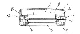
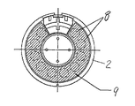
図1、図2において、皿形のケース1の開放端部にはバッフル板2が嵌められ、バッフル板2に開けられた孔にはドライブユニット3が嵌め込まれている。ドライブユニット3は、前述のとおり、図示されないヨーク、磁石、ポールピースなどからなる磁気回路構成部材と、ダイヤフラム状の振動板と、この振動板に固着されて上記磁気回路構成部材で形成されている磁気ギャップ中に配置されているボイスコイルと、を有してなり、スピーカユニットとほぼ同じ構成になっている。
1 and 2, a
上記ドライブユニット3は振動板が配置されている側が前側(図1において下側)になっていて、上記ケース1はバッフル板2の背面側とドライブユニット3の背面側を覆って密閉している。ケース1の内面とバッフル板2およびドライブユニット3の背面との間には適宜容積のバックキャビティ4が形成されている。バッフル板2の前面側外周部にはリング状のイヤパッド5が固着されている。イヤパッド5で囲まれる空間はフロントキャビティ6となっていて、ユーザーが使用しているとき、ユーザーの側頭部にイヤパッド5が押し当てられ、フロントキャビティ6にユーザーの耳が進入する。
In the
バッフル板2は、このバッフル板2およびイヤパッド5で形成されるフロントキャビティ6と外部とを音響的に連通させる内外連通孔10を備えている。内外連通孔10は、バッフル板2の外周縁部に複数個設けられている。バッフル板2の構成をさらに詳しく説明すると、バッフル板2は厚さ方向すなわち前後方向両端にフランジを有し、前側のフランジに内外連通孔10が形成され、この連通孔10と、上記両端のフランジとの間の空間を通じてフロントキャビティ6と外部が連通している。
The
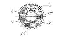
図示の第1実施例では、バッフル板2は、内外連通孔10のほかに、内外連通孔10の形成位置よりも内周側に、バックキャビティ4とフロントキャビティ6を音響的に連通させる前後連通孔8を複数備えている。イヤパッド5はバッフル板2の前面側外周縁に沿って固着されていて、バッフル板2の前面とイヤパッド5との間には音響抵抗材9が介在し、音響抵抗材9は内外連通孔10の前面を覆っている。音響抵抗材9を通してフロントキャビティ6と内外連通孔10とが連通し、結果的にフロントキャビティ6が外部に連通している。
In the illustrated first embodiment, the
図2に示すように、音響抵抗材9はリング状の板の一部を切断した形すなわち部分円弧状に形成され、内外連通孔10を覆うとともに、前後連通孔8も覆っている。換言すれば、内外連通孔10と前後連通孔8は共通の音響抵抗材9で覆われている。ただし、図2に示すように、音響抵抗材9は複数の前後連通孔8の一部を残して覆うことにより、前後連通孔8からなるバックキャビティ4とフロントキャビティ6との間の音響端子の音響抵抗を調整することができるように構成されている。
As shown in FIG. 2, the
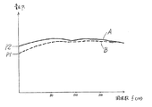
以上説明した第1実施例によれば、フロントキャビティ6と外部とを音響的に連通させる内外連通孔10を備えていることにより、ユーザーが使用しているとき、フロントキャビティ6が密閉されていても、フロントキャビティ6の容積が実質的に拡大されたのと同じになって、ドライブユニット3の振動板が動きやすくなり、また、低音域の音圧が抑制されて低音域の音質を高めることができる。図7は本発明に係るヘッドホンと図8に示すような従来のヘッドホンの周波数特性を示す。横軸は周波数、縦軸は音圧を示す。実線Aは従来のヘッドホンの特性、破線Bは本発明に係るヘッドホンの特性を示す。図7から明らかなように、本発明に係るヘッドホンによれば、低音域の特性がよくコントロールされ、音質が改善されていることがわかる。
According to the first embodiment described above, the front cavity 6 is hermetically sealed when the user uses it by providing the inner and
また、内外連通孔10を音響抵抗材9で覆い、音響抵抗値を適宜設定することにより、低音域の特性をコントロールすることができ、音質(周波数特性)を調整するためにドライブユニット3の振動板の動きを抑制する必要がないため、音質調整による音質の劣化を回避することができる。
Further, by covering the inner and outer communication holes 10 with the
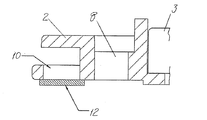
図1、図2に示す実施例では、内外連通孔10と前後連通孔8を共通の音響抵抗材9で覆っていたが、図3、図4に示す第2実施例のように、内外連通孔10のみを覆う音響抵抗材12を用いてもよい。また、上記音響抵抗材12のほかに、前後連通孔8を覆う音響抵抗材を用いてもよい。
In the embodiment shown in FIGS. 1 and 2, the inner and outer communication holes 10 and the front and rear communication holes 8 are covered with a common
図1、図2に示す実施例では、内外連通孔10と前後連通孔8が円形の孔になっていたが、図3に示すように四角形状の孔であってもよい。 In the embodiment shown in FIGS. 1 and 2, the inner and outer communication holes 10 and the front and rear communication holes 8 are circular holes, but may be rectangular holes as shown in FIG.
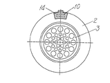
図5、図6は本発明に係るヘッドホンの第3実施例を示す。この実施例が前記実施例と異なる点は、内外連通孔10を開閉することにより音質調整を行う音質調整部材14を有している点である。図5、図6において、音質調整部材14はバッフル板2の外周縁にそってスライド可能に設けられ、音質調整部材14をスライドさせることにより内外連通孔10を開閉することができるように構成されている。図5は音質調整部材14が内外連通孔10を開放した状態を示しており、この状態での周波数特性は図7に破線Bで示す曲線のようになる。図6は音質調整部材14が内外連通孔10を閉鎖した状態を示しており、この状態での周波数特性は図7に実線Aで示す曲線のようになる。このように、音質調整部材14が内外連通孔10を開閉することにより、再生可能な最低周波数の音圧が、図7に示すように、P1またはP2に変化する。
5 and 6 show a third embodiment of the headphones according to the present invention. This embodiment is different from the above embodiment in that it has a sound
音質調整部材14は、内外連通孔10を全開した態様とすべて閉鎖した態様との間で切り換えるようにしてもよいし、内外連通孔10の開閉度を調整することができるようにしてもよい。開閉度を調整可能にしておけば、周波数特性を、図7に示す曲線Aと曲線Bとの間で調整することができる。
The sound
図5、図6では、一つの音質調整部材14が一つの内外連通孔10を開閉するように構成されているが、複数の内外連通孔10を開閉可能な複数の音質調整部材14が一体に連結されて一体的に移動し、複数の内外連通孔10を同時に開閉できるように構成してもよい。また、複数の内外連通孔10の開閉度を複数の音質調整部材14で同時に調整することができるようにいてもよい。
5 and 6, one sound
1 ケース
2 バッフル板
3 ドライブユニット
4 バックキャビティ
5 イヤパッド
6 フロントキャビティ
8 前後連通路
9 音響抵抗材
10 内外連通路
12 音響抵抗材
14 音質調整部材
DESCRIPTION OF SYMBOLS 1
Claims (8)
上記バッフル板は、このバッフル板およびイヤパッドで形成されるフロントキャビティと外部とを音響的に連通させる内外連通孔を有するヘッドホン。 A sealed headphone with a baffle plate, a drive unit attached to the baffle plate, a case that forms a back cavity by sealing the back side of the baffle plate and the drive unit, and an ear pad attached to the front side of the baffle plate There,
The baffle plate is a headphone having an internal / external communication hole for acoustically communicating a front cavity formed by the baffle plate and an ear pad and the outside.
Priority Applications (1)
| Application Number | Priority Date | Filing Date | Title |
|---|---|---|---|
| JP2008256732A JP5253072B2 (en) | 2008-10-01 | 2008-10-01 | headphone |
Applications Claiming Priority (1)
| Application Number | Priority Date | Filing Date | Title |
|---|---|---|---|
| JP2008256732A JP5253072B2 (en) | 2008-10-01 | 2008-10-01 | headphone |
Publications (2)
| Publication Number | Publication Date |
|---|---|
| JP2010087993A true JP2010087993A (en) | 2010-04-15 |
| JP5253072B2 JP5253072B2 (en) | 2013-07-31 |
Family
ID=42251459
Family Applications (1)
| Application Number | Title | Priority Date | Filing Date |
|---|---|---|---|
| JP2008256732A Expired - Fee Related JP5253072B2 (en) | 2008-10-01 | 2008-10-01 | headphone |
Country Status (1)
| Country | Link |
|---|---|
| JP (1) | JP5253072B2 (en) |
Cited By (8)
| Publication number | Priority date | Publication date | Assignee | Title |
|---|---|---|---|---|
| JP2016100649A (en) * | 2014-11-18 | 2016-05-30 | 株式会社オーディオテクニカ | Electroacoustic transducer |
| JP2017158006A (en) * | 2016-03-01 | 2017-09-07 | 株式会社オーディオテクニカ | headphone |
| KR101880735B1 (en) * | 2017-06-09 | 2018-07-23 | 인하대학교 산학협력단 | Noise-cancelling headphone |
| KR101925986B1 (en) * | 2017-09-04 | 2018-12-07 | 김도윤 | Sound improvement device for portable electronic device |
| JP2019047406A (en) * | 2017-09-06 | 2019-03-22 | 株式会社Jvcケンウッド | earphone |
| CN109640211A (en) * | 2019-02-19 | 2019-04-16 | 深圳市澜科创科技有限公司 | A kind of noise cancelling headphone |
| CN111385694A (en) * | 2018-12-26 | 2020-07-07 | 铁三角有限公司 | Head earphone |
| JP2021073828A (en) * | 2021-02-16 | 2021-05-13 | 株式会社Jvcケンウッド | earphone |
Citations (5)
| Publication number | Priority date | Publication date | Assignee | Title |
|---|---|---|---|---|
| JPS5120762Y1 (en) * | 1974-03-15 | 1976-05-29 | ||
| JPS55127487U (en) * | 1979-03-05 | 1980-09-09 | ||
| JPS5641428Y2 (en) * | 1975-08-02 | 1981-09-28 | ||
| JPS575981Y2 (en) * | 1978-03-23 | 1982-02-04 | ||
| JPH05111086A (en) * | 1991-10-14 | 1993-04-30 | Nippon Atsudenki Kk | Headphone |
-
2008
- 2008-10-01 JP JP2008256732A patent/JP5253072B2/en not_active Expired - Fee Related
Patent Citations (5)
| Publication number | Priority date | Publication date | Assignee | Title |
|---|---|---|---|---|
| JPS5120762Y1 (en) * | 1974-03-15 | 1976-05-29 | ||
| JPS5641428Y2 (en) * | 1975-08-02 | 1981-09-28 | ||
| JPS575981Y2 (en) * | 1978-03-23 | 1982-02-04 | ||
| JPS55127487U (en) * | 1979-03-05 | 1980-09-09 | ||
| JPH05111086A (en) * | 1991-10-14 | 1993-04-30 | Nippon Atsudenki Kk | Headphone |
Cited By (11)
| Publication number | Priority date | Publication date | Assignee | Title |
|---|---|---|---|---|
| JP2016100649A (en) * | 2014-11-18 | 2016-05-30 | 株式会社オーディオテクニカ | Electroacoustic transducer |
| JP2017158006A (en) * | 2016-03-01 | 2017-09-07 | 株式会社オーディオテクニカ | headphone |
| KR101880735B1 (en) * | 2017-06-09 | 2018-07-23 | 인하대학교 산학협력단 | Noise-cancelling headphone |
| KR101925986B1 (en) * | 2017-09-04 | 2018-12-07 | 김도윤 | Sound improvement device for portable electronic device |
| JP2019047406A (en) * | 2017-09-06 | 2019-03-22 | 株式会社Jvcケンウッド | earphone |
| CN111385694A (en) * | 2018-12-26 | 2020-07-07 | 铁三角有限公司 | Head earphone |
| CN111385694B (en) * | 2018-12-26 | 2023-11-03 | 铁三角有限公司 | Headset earphone |
| CN109640211A (en) * | 2019-02-19 | 2019-04-16 | 深圳市澜科创科技有限公司 | A kind of noise cancelling headphone |
| CN109640211B (en) * | 2019-02-19 | 2024-03-12 | 深圳市澜科创科技有限公司 | Noise reduction earphone |
| JP2021073828A (en) * | 2021-02-16 | 2021-05-13 | 株式会社Jvcケンウッド | earphone |
| JP7160121B2 (en) | 2021-02-16 | 2022-10-25 | 株式会社Jvcケンウッド | earphone |
Also Published As
| Publication number | Publication date |
|---|---|
| JP5253072B2 (en) | 2013-07-31 |
Similar Documents
| Publication | Publication Date | Title |
|---|---|---|
| JP5253072B2 (en) | headphone | |
| JP5096193B2 (en) | Headphone unit | |
| JP3154214B2 (en) | headphone | |
| JP6380504B2 (en) | headphone | |
| US9094750B2 (en) | Loudspeaker, inner-ear headphone including loudspeaker, and hearing aid including loudspeaker | |
| JP5059501B2 (en) | headphone | |
| JP2011087048A (en) | Headphone | |
| KR101952909B1 (en) | Earphone having pressure equalization structure | |
| JP6727852B2 (en) | headphone | |
| JP2008141589A (en) | Cellular phone mounted with bone conduction speaker | |
| US7350618B2 (en) | Multimedia speaker product | |
| JP2019145962A (en) | earphone | |
| KR101451687B1 (en) | two way speaker having coaxial effect | |
| CN110996225B (en) | Loudspeaker | |
| US10448147B2 (en) | Acoustic device having multiple diaphragms | |
| JP2009284169A (en) | Headphone | |
| KR102442961B1 (en) | Earphone with duct unit dividing pressure equilibruim hole and back hole | |
| JP5253075B2 (en) | Headphone unit and headphones | |
| JP7380314B2 (en) | headphone | |
| WO2022130661A1 (en) | Earphone | |
| JP6583226B2 (en) | headphone | |
| US20240031729A1 (en) | Noise cancellation enabled headphone | |
| KR102577014B1 (en) | Receiver module integrated with a duct | |
| JP2019145964A (en) | earphone | |
| JP7258343B2 (en) | headphone |
Legal Events
| Date | Code | Title | Description |
|---|---|---|---|
| A621 | Written request for application examination |
Free format text: JAPANESE INTERMEDIATE CODE: A621 Effective date: 20111003 |
|
| A977 | Report on retrieval |
Free format text: JAPANESE INTERMEDIATE CODE: A971007 Effective date: 20120820 |
|
| A131 | Notification of reasons for refusal |
Free format text: JAPANESE INTERMEDIATE CODE: A131 Effective date: 20120904 |
|
| A521 | Written amendment |
Free format text: JAPANESE INTERMEDIATE CODE: A523 Effective date: 20121105 |
|
| TRDD | Decision of grant or rejection written | ||
| A01 | Written decision to grant a patent or to grant a registration (utility model) |
Free format text: JAPANESE INTERMEDIATE CODE: A01 Effective date: 20130319 |
|
| A61 | First payment of annual fees (during grant procedure) |
Free format text: JAPANESE INTERMEDIATE CODE: A61 Effective date: 20130416 |
|
| R150 | Certificate of patent or registration of utility model |
Ref document number: 5253072 Country of ref document: JP Free format text: JAPANESE INTERMEDIATE CODE: R150 Free format text: JAPANESE INTERMEDIATE CODE: R150 |
|
| FPAY | Renewal fee payment (event date is renewal date of database) |
Free format text: PAYMENT UNTIL: 20160426 Year of fee payment: 3 |
|
| R250 | Receipt of annual fees |
Free format text: JAPANESE INTERMEDIATE CODE: R250 |
|
| R250 | Receipt of annual fees |
Free format text: JAPANESE INTERMEDIATE CODE: R250 |
|
| LAPS | Cancellation because of no payment of annual fees |