JP2010087455A - Sealed container and cover opening/closing system for sealed container - Google Patents
Sealed container and cover opening/closing system for sealed container Download PDFInfo
- Publication number
- JP2010087455A JP2010087455A JP2009006602A JP2009006602A JP2010087455A JP 2010087455 A JP2010087455 A JP 2010087455A JP 2009006602 A JP2009006602 A JP 2009006602A JP 2009006602 A JP2009006602 A JP 2009006602A JP 2010087455 A JP2010087455 A JP 2010087455A
- Authority
- JP
- Japan
- Prior art keywords
- lid
- opening
- pod
- latch mechanism
- engaged
- Prior art date
- Legal status (The legal status is an assumption and is not a legal conclusion. Google has not performed a legal analysis and makes no representation as to the accuracy of the status listed.)
- Granted
Links
Images


Abstract
Description
本発明は、半導体製造プロセス等において、ポッドと呼ばれる搬送容器に内部保持されたウエハを半導体処理装置間にて移送する際に用いられる、所謂FIMS(Front-Opening Interface Mechanical Standard)システムに関する。より詳細には、当該FIMSシステムにおいて用いられる、ウエハを収容する密閉容器たる所謂FOUP(Front-Opening Unified Pod)と呼ばれるポッド、及び当該ポッドの蓋を開閉して該ポッドに対するウエハの移載を行うFIMSシステムたる蓋開閉システムに関する。 The present invention relates to a so-called FIMS (Front-Opening Interface Mechanical Standard) system used when a wafer internally held in a transfer container called a pod is transferred between semiconductor processing apparatuses in a semiconductor manufacturing process or the like. More specifically, a so-called FOUP (Front-Opening Unified Pod) used in the FIMS system, which is a hermetically sealed container for accommodating a wafer, and a wafer is transferred to the pod by opening and closing the lid of the pod. The present invention relates to a lid opening / closing system as a FIMS system.
近年、半導体製造プロセスは、処理装置内部、ポッド(ウエハの収容容器)、及び当該ポッドから処理装置への基板受け渡しを行う微小空間のみを高清浄状態に保持し、その他の空間の清浄度はある程度のレベルに維持して行われている。ポッドは、その内部に複数のウエハを平行且つ隔置した状態で保持可能な棚と、外面を構成する面の一つにウエハ出し入れに用いられる開口とを有する略立方体形状を有する本体と、その開口を閉鎖する蓋とから構成される。この開口が形成されている面がポッドの底面ではなく一側面(微小空間に対して正対する面)に位置するポッドを前述したFOUPと総称している。 In recent years, the semiconductor manufacturing process keeps the inside of a processing apparatus, a pod (wafer container), and a very small space for transferring a substrate from the pod to the processing apparatus in a highly clean state, and the cleanliness of other spaces is to some extent. Has been done to maintain the level. The pod has a substantially cubic body having a shelf that can hold a plurality of wafers in parallel and spaced apart from each other, and an opening used for loading and unloading the wafer on one of the surfaces constituting the outer surface. And a lid that closes the opening. The pod where the opening is formed is not the bottom surface of the pod but on one side surface (the surface facing the minute space) and is collectively referred to as FOUP.
また、上述した微小空間は、ポッドの開口と向かい合う開口部と、開口部を閉鎖するドアと、半導体処理装置側に設けられた処理装置側の他の開口部と、開口部からポッド内部に侵入してウエハを保持すると共に該処理装置側の他の開口部を通過して処理装置側にウエハを搬送する移載ロボットとを有している。また、微小空間を形成する構成は、ドア正面にポッド開口が正対するようポッドを支持する載置台を有している。この載置台の上面には、ポッド下面に設けられた位置決め用の穴に嵌合されてポッドの載置位置を規定する位置決めピンと、ポッド下面に設けられた被クランプ部と係合してポッドを載置台に対して固定するクランプユニットとが配置されている。通常、載置台はドア方向に対して所定距離の前後移動が可能となっている。ポッド内のウエハを処理装置に移載する際には、ポッドが載置された状態でポッドの蓋がドアと接触するまでポッドを移動させ、接触後にドアによってポッド開口部からその蓋が取り除かれる。これら操作によって、ポッド内部と処理装置内部とが微小空間を介して連通することとなり、以降ウエハの移載操作が繰り返して行われる。この載置台、ドア、開口部、ドアの開閉機構、開口部が構成された微小空間の一部を構成する壁等を含めて、前述したFIMSシステムと総称される。 In addition, the above-described minute space enters the inside of the pod through the opening facing the opening of the pod, the door for closing the opening, the other opening on the side of the processing apparatus provided on the semiconductor processing apparatus side, and the opening. And a transfer robot that holds the wafer and passes the other opening on the processing apparatus side to convey the wafer to the processing apparatus side. Moreover, the structure which forms minute space has the mounting base which supports a pod so that a pod opening may face in front of a door. On the upper surface of the mounting table, a positioning pin that is fitted into a positioning hole provided on the lower surface of the pod and defines the mounting position of the pod, and a clamped portion provided on the lower surface of the pod are engaged with the pod. A clamp unit that is fixed to the mounting table is disposed. Usually, the mounting table can move back and forth a predetermined distance with respect to the door direction. When the wafer in the pod is transferred to the processing apparatus, the pod is moved with the pod being placed until the lid of the pod comes into contact with the door, and after the contact, the lid is removed from the pod opening by the door. . By these operations, the inside of the pod and the inside of the processing apparatus communicate with each other through a minute space, and the wafer transfer operation is repeated thereafter. The mounting table, the door, the opening, the opening / closing mechanism of the door, the wall that forms part of the minute space in which the opening is configured, and the like are collectively referred to as the FIMS system described above.
例えば従来のポッドの蓋には、特許文献1に詳細に開示されるように蓋外周から外方方向に伸縮可能な爪が配され、当該爪の伸縮によってポッド本体−蓋の係合及び解除の各々の状態を得ることとしている。当該爪の伸縮は、当該爪と連結されて蓋の中央領域内の所定位置に配置された被操作部に対して、蓋表面の外部から所謂キー部材を嵌合させてこれを操作することで行われている。このような部材の接触、回動、その際に生じる摺動等により、通常は半導体製造上問題視されるべき塵が発生する。しかし、これら塵は蓋の表面とドアの表面との間の微小隙間から当該隙間の外部に拡散する以前に、ダウンフローが形成された微小空間内に移動される。このため、当該塵の微小空間或いはポッド内への拡散は問題視されるレベルには至らず、特に当該塵に対する対応は為されていなかった。また、通常清浄度の劣った空間を搬送されることから、ポッド本体の外周面及び蓋の表面には当該空間で付着した塵、或いは外気に含まれた例えばハイドロカーボン等が吸着している。これらに関しても、前述したキー部材等から生じた塵と同様に、ダウンフローによる抑制効果が好適に機能していると考えられていた。 For example, as disclosed in detail in Patent Document 1, a conventional pod lid is provided with a pawl that can extend and retract outward from the outer periphery of the lid. We are going to get each state. The expansion and contraction of the claw is performed by fitting a so-called key member from the outside of the lid surface to an operated part that is connected to the claw and disposed at a predetermined position in the central region of the lid. Has been done. Due to such contact and rotation of the members, sliding that occurs at that time, dust that is normally regarded as a problem in semiconductor manufacturing is generated. However, these dusts are moved from the minute gap between the surface of the lid and the surface of the door into the minute space where the downflow is formed before diffusing outside the gap. For this reason, the diffusion of the dust into the minute space or the pod has not reached the level considered as a problem, and no countermeasure has been particularly taken against the dust. Further, since the space is usually transported in a poorly clean space, dust adhering in the space or, for example, hydrocarbon contained in the outside air is adsorbed on the outer peripheral surface of the pod body and the surface of the lid. Also regarding these, it was thought that the suppression effect by a downflow was functioning suitably like the dust generated from the key member etc. which were mentioned above.
ここで、半導体デバイスは、素子の高機能化及び小型化が漸次進められている。このため素子に用いられる配線幅、デザインルール等がより狭められ、従来であれば問題とならなかったより小さな塵の存在にも留意する必要が生じてきている。このような極微小な塵は、従来対応策が練られてきた塵と異なり、所謂ブラウン運動や微小な静電気の影響等、従来とは異なる動作によって空間を移動する。具体的には、このような極微細な塵は、前述したダウンフローによって微小空間の下方に押し流し更に外部空間に排出しようとしても、単純に気流に流されずに微小空間内に漂い出してくる可能性がある。なお、特許文献2には、蓋側に爪を配置するのではなく、ポッド側の開口外部に回動式のレバーを配置して蓋が開口を閉鎖した状態において当該レバーが蓋表面側から蓋を押さえ込む構成が開示されている。当該構成では、特許文献1におけるキー部材に起因する塵の発生は開口の周囲で生じることとなり、蓋及びこれを保持するドアからの塵の拡散の程度は引用文献1の構成よりは低減できる可能性がある。しかし、蓋開閉の操作前に当該レバーの操作を予め行っておく必要が存在し、且つ当該操作のための構成が開口部周囲に存在することから、外部空間に存在する極微小な塵が微小空間側に拡散してくる恐れが存在する。
Here, semiconductor devices have been gradually improved in functionality and size. For this reason, the wiring width, design rule, etc. used for the element are narrowed, and it has become necessary to pay attention to the presence of smaller dust that was not a problem in the past. Unlike the dust for which countermeasures have been conventionally prepared, such extremely fine dust moves in the space by operations different from the conventional one, such as so-called Brownian motion and the influence of minute static electricity. Specifically, even if such extremely fine dust is pushed down the minute space by the downflow described above and further exhausted to the outside space, it is not simply flowed by the air current but drifts into the minute space. there is a possibility. In
本発明は以上の状況に鑑みて為されたものであり、ポッド開口を閉鎖する蓋の表面に付着する極微小な塵の影響を抑制し、且つ蓋開閉時において当該開閉操作に伴う塵の発生、及び発生した塵の微小空間或いはポッド内部への拡散を抑制する密閉容器たるポッド及び当該密閉容器に対応する蓋開閉システムの提供を目的としている。 The present invention has been made in view of the above situation, suppresses the influence of extremely fine dust adhering to the surface of the lid that closes the pod opening, and generates dust when the lid is opened and closed. Another object of the present invention is to provide a pod that is a sealed container that suppresses diffusion of generated dust into a minute space or inside the pod, and a lid opening / closing system corresponding to the sealed container.
上記課題を解決するために、本発明に係る密閉容器は、平板形状からなり、該平板形状内に設けられた被係合部を有する蓋と、被収容物を収容可能な内部空間と、該内部空間と外部空間とを連通させると共に蓋における平板形状の一面によって閉鎖される開口と、該開口の周囲より開口形成面に平行に張り出し且つ開口を閉鎖した状態にある蓋を収容する収容空間を構成するフランジ部と、蓋を収容空間に収容した状態において被係合部に対応する位置に配置されるフランジ部の外面から収容空間に連通する挿通孔と、を有する容器本体部と、開口形成面に平行な一軸に沿って移動可能であって該一軸の方向に延在するラッチ本体部と、該ラッチ本体部から一軸の延在方向と異なる方向に突出する連結部と、該連結部先端に配置される係合部とを有するラッチ機構と、を有し、少なくとも係合部は挿通孔から収容空間内に至り、係合部は収容空間内に配置される蓋の被係合部に係合し、本体部が前記一軸に沿って移動することによって係合部と被係合部との係合及び係合の解除とが為されることを特徴としている。 In order to solve the above-mentioned problems, a sealed container according to the present invention has a flat plate shape, a lid having an engaged portion provided in the flat plate shape, an internal space capable of storing an object to be stored, An opening space that allows the internal space and the external space to communicate with each other and that is closed by a flat plate-shaped surface of the lid, and that accommodates the lid that protrudes in parallel to the opening forming surface from the periphery of the opening and closes the opening. A container main body portion having a flange portion to be configured, and an insertion hole communicating with the accommodation space from the outer surface of the flange portion arranged at a position corresponding to the engaged portion in a state where the lid is accommodated in the accommodation space, and opening formation A latch main body that is movable along one axis parallel to the surface and extends in the direction of the one axis; a connecting portion that protrudes from the latch main body in a direction different from the extending direction of the one axis; and a tip of the connecting portion Engaging part A latch mechanism having at least an engaging portion extending from the insertion hole into the receiving space, the engaging portion engaging with an engaged portion of a lid disposed in the receiving space, and the main body portion By moving along one axis, the engaging portion and the engaged portion are engaged and released.
なお、上述した密閉容器において、被係合部は、平板形状の外周面の延在方向に沿って延在する第一の直線部と、該平板形状の一面側に開口端を有して蓋の厚さ方向に延在する第二の直線部、とを含むL字形状からなり、該係合部はL字形状の第一の直線部を構成する内側壁と係合可能であって、本体部が該一軸に沿って移動することにより該係合部が第二の直線部に移動することによって係合状態が解除される構成であることが好ましい。なお、この場合、被係合部における第一の直線部及び第二の直線部は平板形状の外周面に開口する凹部からなることがより好ましい。また、前述した内側壁は、第一の直線部における第二の直線部との連結端部とは異なる端部側に係合部が移動することに応じて、該係合部が内側壁に対して加える付勢力を変化させる凹凸及び斜面の少なくとも何れかよりなる形状を有するとより好ましい。また、当該容器にあっては、連結部がラッチ本体部から突出する方向は一軸の延在方向に対して垂直な方向であることが好ましい。また、該係合部は、内側壁に当接して転動可能な円板状のローラーを有することがより好ましい。更に、ラッチ機構は、係合部を被係合部と係合する位置に停止保持する付勢力を該係合部に付与する付勢手段を更に有することがより好ましい。或いは、ラッチ本体部はラッチ機構を一軸に沿って移動可能に支持するスライドレールを更に有し、スライドレールはフランジ部における容器本体部側の一面に配置されることがより好ましい。 In the above-described closed container, the engaged portion includes a first straight portion extending along the extending direction of the flat plate-shaped outer peripheral surface, and an open end on the one surface side of the flat plate shape. A second linear portion extending in the thickness direction, and the engaging portion is engageable with an inner wall constituting the L-shaped first linear portion, It is preferable that the engagement state is released when the main body portion moves along the one axis and the engagement portion moves to the second linear portion. In this case, it is more preferable that the first straight portion and the second straight portion in the engaged portion are formed of a concave portion opened on a flat plate-shaped outer peripheral surface. Further, the inner wall described above is moved to the inner wall in accordance with the movement of the engaging portion to the end side different from the connecting end portion of the first straight portion with the second straight portion. It is more preferable to have a shape made of at least one of irregularities and slopes that change the urging force applied thereto. Moreover, in the said container, it is preferable that the direction where a connection part protrudes from a latch main-body part is a direction perpendicular | vertical with respect to the uniaxial extension direction. Further, it is more preferable that the engaging portion has a disk-shaped roller that can roll while contacting the inner wall. Furthermore, it is more preferable that the latch mechanism further includes a biasing unit that applies a biasing force to the engaging portion to stop and hold the engaging portion at a position where the engaging portion is engaged with the engaged portion. Alternatively, it is more preferable that the latch main body further includes a slide rail that supports the latch mechanism so as to be movable along one axis, and the slide rail is disposed on one surface of the flange main body side.
また、上記課題を解決するために、本発明に係る蓋開閉システムは、上述した密閉容器に対して該蓋を開閉して密閉容器内部への被収容物の挿脱を可能とする蓋開閉システムであって、開口部を有する微小空間と、該開口部を略閉鎖する位置と開放する位置との間で移動可能なドアと、密閉容器がドアによる蓋の開閉が行われる位置に存在した際にラッチ機構を操作可能であって、該開口部の周囲に配置されるラッチ機構駆動手段と、を有することを特徴としている。なお、当該蓋開閉システムにおいて、ラッチ機構駆動手段は、該ラッチ本体部の移動軸である該一軸と同軸に配置されて該ラッチ機構を移動軸に沿って押圧可能なロッド、及び該ロッドを移動軸に沿って伸縮可能に支持するアクチュエータを有することが好ましい。或いは該密閉容器が載置された状態で該密閉容器を前記開口部に対して接近或いは離間させる容器載置台を更に有し、該ラッチ機構駆動手段は、容器載置台の移動により該容器載置際に対して相対移動可能なカム面と、容器載置台に配置されたカム面に従動可能なカム手段とによって構成されて該容器載置台の移動に伴う該カム面の変化に準じてラッチ機構に対して押圧力を付与するカム機構を有することが好ましい。更に、該密閉容器は、該密閉容器が蓋の開閉位置に存在した際に、フランジ部の外周面を覆うフランジカバーを更に有することがより好ましい。 In order to solve the above-mentioned problems, a lid opening / closing system according to the present invention opens and closes the lid with respect to the above-described sealed container to enable insertion / removal of an object to be contained in the sealed container. And when the minute space having the opening, the door movable between the position where the opening is substantially closed and the position where the opening is opened, and the position where the closed container is opened and closed by the door And a latch mechanism driving means disposed around the opening. In the lid opening / closing system, the latch mechanism driving means is arranged coaxially with the one axis that is the movement axis of the latch body, and can move the rod along the movement axis. It is preferable to have an actuator that is supported to extend and contract along the axis. Alternatively, the apparatus further includes a container mounting table that moves the closed container closer to or away from the opening in a state where the sealed container is mounted, and the latch mechanism driving means moves the container mounting table. And a latch mechanism according to a change in the cam surface accompanying the movement of the container mounting table. It is preferable to have a cam mechanism that applies a pressing force to the. Furthermore, it is more preferable that the airtight container further includes a flange cover that covers the outer peripheral surface of the flange portion when the airtight container exists at the open / close position of the lid.
本発明によれば、ポッドに蓋が固定された状態において蓋の表面は平坦な面となる。また、蓋には外部からアクセスされ且つ操作される所謂可動部材も存在しなくなる。従って、従来構成のようなドア表面における所謂ラッチ爪の操作に伴う発塵を完全に無くすことが可能となる。また、従来と異なり、蓋は内部に種々の構成を有さず、単なる平板状の部材となる。従って、洗浄による塵等の除去が容易になると共に、排除困難な状態での塵等の蓋への付着が無くなり、蓋単体で考えた場合であっても塵等に対する清浄度を高く維持することが可能となる。特に、蓋に設けられる被係合凹部は単なる溝形状であることから、加工、洗浄が従来の蓋の場合と比較して、非常に容易となる。また、半導体製造工程に用いられるウエハのサイズは、現状の所謂300mmφから450mmφへの移行が検討されている。このような大口径のウエハを収容するポッドでは、蓋のサイズの大型化と同時に蓋の反り、撓みといった変形の防止、ポッドに対する蓋の固定の確実性と固定強度の確保等が求められる。本発明に係るポッドの蓋の構造では、蓋構造が単純な平板構造となることから、蓋の軽量化が容易であると共に蓋の軽量化を為しつつ、蓋の剛性を高める構造を採用することも可能となる。従って、このような要望に対して容易且つ確実に対応することが可能となる。 According to the present invention, the surface of the lid becomes a flat surface when the lid is fixed to the pod. Also, there is no so-called movable member that is accessed and operated from the outside on the lid. Therefore, it is possible to completely eliminate dust generation due to operation of a so-called latching claw on the door surface as in the conventional configuration. Further, unlike the conventional case, the lid does not have various configurations inside, and is merely a flat plate member. Therefore, dust can be easily removed by washing, and dust can be prevented from adhering to the lid when it is difficult to remove, so that the cleanliness against dust can be kept high even when considered as a single lid. Is possible. In particular, since the engaged recess provided in the lid has a simple groove shape, processing and cleaning are much easier than in the case of a conventional lid. Further, the shift of the wafer size used in the semiconductor manufacturing process from the current so-called 300 mmφ to 450 mmφ is being studied. In a pod that accommodates such a large-diameter wafer, it is required to increase the size of the lid, to prevent deformation such as warping and bending of the lid, to ensure the fixing of the lid to the pod and to ensure the fixing strength. In the structure of the lid of the pod according to the present invention, since the lid structure is a simple flat plate structure, a structure that increases the rigidity of the lid while facilitating weight reduction of the lid and reducing the weight of the lid is adopted. It is also possible. Therefore, it is possible to easily and reliably respond to such a request.
また、本発明によれば、蓋をポッド本体に対して固定した状態で、常に蓋がポッド開口を密閉する方向に付勢される構成とすることも可能である。当該構成とすることによって、ポッド自体の気密性の向上、及び搬送時等における蓋の振動による発塵の可能性を低減が可能となる。更に、当該蓋の表面を平坦にできることから、当該蓋或いはドアの対向面の何れかにシール部材を配することにより、これら蓋及びドアに挟まれる空間をその周囲空間から完全に分離することとなり、蓋が微小空間内に持ち込んだ塵、外気等の拡散を確実に防止できる。更に、ドアが蓋を吸着保持することに加え、シール部材により形成される蓋とドアとに挟まれた閉鎖空間を減圧化してドアの保持力を高めることも可能となる。また、蓋開閉操作を行うための構成の配置及び当該構成の動作領域が、基本的にポッド外部及び微小空間の外部で行われることとなる。従って、仮にこれら構成による発塵が生じた場合であっても、当該塵のポッド内部或いは微小空間内部への拡散の頻度は従来構成の場合と比較して大きく低減される。 Further, according to the present invention, it is possible to adopt a configuration in which the lid is always urged in the direction of sealing the pod opening while the lid is fixed to the pod body. With this configuration, it is possible to improve the airtightness of the pod itself and reduce the possibility of dust generation due to the vibration of the lid during transportation. Furthermore, since the surface of the lid can be flattened, the space between the lid and the door is completely separated from the surrounding space by arranging a sealing member on either the lid or the facing surface of the door. The lid can reliably prevent the diffusion of dust, outside air, etc. brought into the minute space. Further, in addition to the door holding the lid by suction, it is also possible to increase the holding force of the door by reducing the pressure of the closed space sandwiched between the lid formed by the seal member and the door. In addition, the arrangement of the configuration for performing the lid opening / closing operation and the operation area of the configuration are basically performed outside the pod and outside the minute space. Therefore, even if dust generation occurs due to these configurations, the frequency of diffusion of the dust into the pod or the minute space is greatly reduced as compared with the conventional configuration.
また、本発明においてポッドに対して蓋を固定する所謂ラッチ機構が垂直方向に駆動する様式とされ、且つ下方位置において蓋固定を為す構造とした場合、ラッチ機構自身の自重によってポッドに対する蓋の固定が為されることとなる。この場合、蓋開閉時におけるラッチ機構を駆動操作する構成に動作不良が生じた場合であっても、常にラッチ機構が蓋固定位置に存在可能であることから、蓋の閉鎖は保たれてポッド内の清浄状態を維持し続けることが可能となる。また、例えば特許文献1に開示する構成の場合、キー部材とラッチ機構の被操作部とが内部で噛み込む等の事態が生じてこれら構成の分離が困難となった場合、分離のために、蓋を分解する等の操作を行う必要が生じる可能性がある。これに対して、本発明においては、ラッチ機構に対してポッドの側面等、微小空間に対する所謂外部空間側からのアクセスを為し、ラッチ機構に強制的な動作を行わせることが可能である。従って、ラッチ機構等に異常が生じてその操作が困難となった場合であっても、強制的な操作を容易に為すことにより、当該ラッチ機構に関連するトラブルから回復することか可能となる。更に、ラッチ状態の適否の検出についても特別の構成の付加、操作の確立を要さず、外部から目視によってラッチ状態を容易に確認することが可能となる。 In the present invention, when the so-called latch mechanism for fixing the lid to the pod is driven in the vertical direction and the lid is fixed at the lower position, the lid is fixed to the pod by its own weight. Will be done. In this case, even if a malfunction occurs in the configuration for driving the latch mechanism when the lid is opened / closed, the latch mechanism can always exist at the lid fixing position, so that the lid is kept closed and the pod is kept inside. It is possible to continue to maintain the clean state. Further, in the case of the configuration disclosed in Patent Document 1, for example, when separation of these configurations becomes difficult due to a situation in which the key member and the operated portion of the latch mechanism are bitten inside, for separation, It may be necessary to perform operations such as disassembling the lid. On the other hand, in the present invention, the latch mechanism can be forcedly operated by accessing the latch mechanism from the side of the so-called external space such as the side surface of the pod. Therefore, even when an abnormality occurs in the latch mechanism or the like and the operation becomes difficult, it is possible to recover from a trouble related to the latch mechanism by making the forced operation easy. Furthermore, it is not necessary to add a special configuration or establish an operation for detecting the suitability of the latched state, and the latched state can be easily confirmed visually from the outside.
更に、本発明においては、ラッチ機構の操作を為す駆動機構において、当該ラッチ機構を操作するための操作部(後述する駆動接触面)の大きさを任意に設定可能である。従って、ドアによって蓋を開放する際にポッドを停止する位置精度を従来の場合と比較して低くすることも可能である。従来構成の場合、載置位置に対する蓋の固定位置、開口部に対するポッドの固定位置、ラッチ機構に起因した蓋に対するドアの当接位置を全て高い位置精度で満たさなければ、ポッドからの蓋の取り外しとポッド内部と微小空間との連通を為すことができなかった。しかし、本発明によれば、少なくともラッチ機構に起因する蓋及びポッドの停止精度の要件が緩和されることから、例えば蓋開閉装置の動作プログラムの構成の簡素化や、実際の操作上の安定性といった効果が得られる。 Furthermore, in the present invention, in the drive mechanism for operating the latch mechanism, the size of the operation portion (drive contact surface described later) for operating the latch mechanism can be arbitrarily set. Therefore, it is possible to reduce the positional accuracy for stopping the pod when the lid is opened by the door as compared with the conventional case. In the case of the conventional configuration, the lid is removed from the pod unless the lid fixing position relative to the mounting position, the pod fixing position relative to the opening, and the door abutting position due to the latch mechanism are all satisfied with high positional accuracy. It was not possible to communicate with the interior of the pod and the minute space. However, according to the present invention, at least the requirements for stopping accuracy of the lid and the pod due to the latch mechanism are relaxed. For example, the configuration of the operation program of the lid opening / closing device is simplified and the actual operational stability is improved. The effect is obtained.
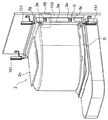
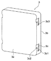
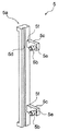
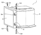
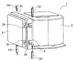
次に、本発明の一実施形態について、以下に図面を参照して説明する。図1Aは、本発明の一実施形態に係る密閉容器たるポッドが蓋開閉システムたるFIMSの蓋開閉位置に存在した状態におけるこれら構成を斜視図により示している。また、図1Bは図1Aに示す状態における後述するラッチ機構のローラー部の係合状態を示しており、領域1Bの構成を拡大して示す図である。図2はポッドの蓋の概略斜視図を、図3はポッドの本体の概略斜視図を、また、図4はポッド本体に固定されるラッチ機構の概略斜視図を各々示している。更に、図5Aは載置台及び微小空間の開口部を構成する壁を側面から見た状態を示し、図5Bはこれら状態をポッドが載置される正面側から見た状態を示している。 Next, an embodiment of the present invention will be described below with reference to the drawings. FIG. 1A is a perspective view showing these configurations in a state where a pod that is a sealed container according to an embodiment of the present invention is present at a lid opening / closing position of a FIMS that is a lid opening / closing system. 1B shows an engagement state of a roller portion of a latch mechanism described later in the state shown in FIG. 1A, and is an enlarged view of the configuration of the region 1B. 2 is a schematic perspective view of the lid of the pod, FIG. 3 is a schematic perspective view of the pod body, and FIG. 4 is a schematic perspective view of a latch mechanism fixed to the pod body. Further, FIG. 5A shows a state where the mounting table and the wall constituting the opening of the minute space are viewed from the side, and FIG. 5B shows a state where these states are viewed from the front side where the pod is placed.
本発明に係る密閉容器たるポッド1は、容器本体であるポッド本体2、蓋3、及びポッド本体2に対して摺動可能に取り付けられるラッチ機構5から構成される。ポッド本体2は略立方体形状であって内部にウエハ等の被収容物をその高さ方向に複数枚並置して収容する内部空間を有する。なお、ポッド本体はウエハを収容可能な種々の形態とすることが可能であるが、基本形状が立方体形状であることから、本明細書においては略立方体形状として定義している。ポッド本体2は、該略立方体形状における一側面に当該収容空間に連通する開口2aを有している。該開口2aは、前述した内部空間を外部空間と連通させる。当該一側面には、更に当該開口2aの周囲を囲むようにして、該開口2aを含む開口平面と平行な平面内にて該開口2aの周囲から外方に張り出したフランジ部2cが形成されている。フランジ部2cは当該一側面と平行な側端面を有し、当該側端面は後述する蓋開閉システムたるロードポートの開口周囲壁と対向する。フランジ部2cは、蓋3の厚さ以上の厚さを有すると共に、平板形状を有する蓋3の平板状の一面(後述する裏面3a)によって開口2aを閉鎖する際に当該蓋3が嵌合可能な収容空間2dを有する。即ち、蓋3は、開口2a閉鎖時において収容空間2dに収容される。
A pod 1 as a sealed container according to the present invention includes a
また、フランジ部2cの外周面、本形態においては外側面に対して、外部空間から該収容空間2dに連通する挿通孔として、矩形状のローラー部挿通孔2eが設けられる。当該ローラー部挿通孔2eは、フランジ部2cの両外側面の各々に対して、上下2箇所に配置される。また、本形態では、当該フランジ部2cに対して、ラッチ機構5が摺動可能に支持されるスライドレール2gも配置される。該スライドレール2gは、フランジ部2cにおける前述した側端面と反対側の面(ポッド本体側に位置する面)である裏面上であって、外側面と隣接し且つ該外側面の延在方向に延在するように配置される。更に、ポッド本体2には、更に不図示のポッド搬送用ロボットによって保持される部分である被保持フランジ2hが上部に、また載置台と実際に当接して該載置台に固定される不図示の被係合部等が配置される被固定フランジ2iが下部に配置される。なお、これら被保持フランジ2h及び被固定フランジ2iは本発明に係るポッドの特徴的構成と関連性を有しないため、ここでの説明は省略する。
In addition, a rectangular roller
本実施形態における蓋3は、ポッド本体2の開口2aを閉鎖した際に内部空間に面する裏面3a及び外部空間側に配置される表面3bを対向面とする平板状の部材からなる。また、平板形状の外周面、本本形態においては外側面に対して、前述したポッド本体2におけるローラー部挿通孔2eに対応した上下位置に対して被係合凹部3cが一対配置される。被係合部たる被係合凹部3cは、当該被係合凹部3cが形成される蓋3の外側面の延在方向に伸びる第一の直線部3c1と、該第一の直線部と連通して該第一の直線部の延在方向とは垂直な方向に延在し、蓋3の裏面3aに端部が開口する第二の直線部3c2とから構成されるL字形状を有する。第一の直線部の長さ及び幅は、前述したポッド本体2に設けられるローラー部挿通孔2eと一致する長さ及び幅を有する。また、該第一の直線部3c1において蓋3の裏面3a側に位置して係合凹部の一部を構成する内側壁3c3は後述するローラー部5bと係合する係合面として機能する。なお、当該蓋3の表面3bには、後述するドアの吸着パッドによって吸着保持される際の被吸着領域において、効率的な吸着保持を可能とするように表面研磨処理が施されている。ここで、蓋表面3bには、清浄度の劣る空間内でポッドを搬送した際に付着した塵等が存在する。従って、これら吸着パッドによって封止して微小空間内への拡散を防止する観点から、当該領域は該表面3bのほぼ全域を含むように構成されることが好ましい。
The
ラッチ機構5は、ラッチ本体部5a、係合部たるローラー部5b、及びラッチ本体部5aとローラー部5bとを連結する連結部5cを有する。ラッチ本体部5aは一方向に延在する角柱状の部材であって、当該ラッチ本体部5aの第一の対向面5dと連結部5cにおける第二の対向面5fにおいてポッド本体2のフランジ部2cの裏面及び側面に各々対向している。第一の対向面5dには、前述したスライドレール2gを摺動可能に収容するために、該第一の対向面5d上においてラッチ本体部5aの延在方向に沿って延在するガイド溝5gが配置される。連結部5cは、第一の対向面5dの形成面からラッチ本体部5aの延在方向に対して垂直な方向に突き出し、前述したローラー部挿通孔2eに対応するように上下位置に一対配置される。なお、本実施形態では、第一の対向面5d及び第二の対向面5fは、実際にはフランジ2cに対して微小間隔を保持して対向し、当接、摺動等が生じない構造としている。なお、これら構成の配置、例えばラッチ本体部5aからの連結部5cの突き出し方向等は、当該実施形態に限定されない。即ち、延在方向である一軸に沿って移動可能なラッチ本体部5aから当該一軸の方向とは異なる特定の方向に連結部5cが突き出しており、且つ連結部5cが係合部たるローラー部5bを支持する内容を満足する構造であれば良い。
The
ローラー部5bは、フランジ部2cに設けられたローラー部挿通孔2eを介して蓋収容空間2d内に突き出し、前述した被係合凹部3cの内側壁3c3の一部と当接する。ローラー部5bは円板形状を有し、当該底面に対して垂直な回転軸5eを介して連結部5cによって軸支されている。該回転軸5eは、ラッチ本体部5aの延在方向、及び連結部5cの突き出し方向各々と垂直な方向に延在する。当該構成により、該回転軸5eに垂直な面内をローラー部5bが平行移動する、即ちラッチ本体部5aが延在方向に摺動する際には、ローラー部5bは回転軸5e周りに転動して円板外周面は当接する該内側壁に対する当接状態を維持しつつ、当接位置を変えることとなる。なお、本実施形態ではローラー部5bにおける円板外周面にゴム等弾性を有する部材を貼り付けて、該円板の周面方向に弾性を付与する構造としている。これにより、ローラー部5bの回転移動時においても当接部が回転せずに摺動することが防止され、発塵を抑制することが可能となる。
The
本実施形態では、ガイドレール2gとガイド溝5gとによってポッド本体2に対するラッチ機構5の取り付けを為している。これによりラッチ機構5の蓋本体2に対する不要な接触を無くし、該接触による発塵を防止している。しかし、ポッド本体2に対するラッチ機構5の取り付けを強固にし、摺動時の所謂がた等の低減を目的として、ガイド溝5gとローラー部5bの円板外周面の一部とによって、矩形状のローラー部挿通孔2eの一内側壁とガイドレール2gとの間の部分を挟持することにより、ラッチ機構5をポッド本体2に対して取り付けることとしても良い。この場合、前述したローラー部5bの円板外周面に弾性体を付加することによって、矩形状のローラー部挿通孔2eの一内側壁と係合凹部の内側壁3c3の両者に対して、ローラー部5bが適度な押圧力を有して当接することができる。これら部材間の当接部分においてある程度発塵することは避けられない。従ってこれら当接部分での摩耗特性に留意した耐磨耗性材料等を用いる、或いは低発塵性のベアリングからなるローラーを用いる等により、ラッチ機構5の動作に起因する発塵を更に抑制することが可能となる。
In the present embodiment, the
次に、ラッチ機構5によるポッド本体2に対する蓋3の固定様式について以下に述べる。図1A中に示すように、蓋3がポッド本体2における収容空間2dに収容されて開口2aを閉鎖した状態において、ローラー部5bはローラー挿通孔2eの下方、即ちL字状の被係合凹部3cにおける第一の直線部3c1の閉鎖端部に存在している。なお、ラッチ機構5は自重の影響によって当該閉鎖端部に存在することもできるが、本形態ではローラー部5bに対して弾性を付与し、当該位置においてローラー部5bが蓋3に対してポッド本体2に密着する方向の付勢力を与えることとし、更に当該付勢力の反力によって当該位置に停止保持される構造としている。当該状態からラッチ機構5をラッチ開放位置、即ち図1Aにおける上方にスライドさせると、ローラー部5bはL字状の被係合凹部3cにおける第一の直線部3c1と第二の直線部3c2とが交錯する位置に移動する。この移動によって、ローラー部5bは蓋裏面3aに開口する第二の直線部3c2に位置することとなり、当接する内側壁3c3が存在しなくなる。従って、蓋3に対するローラー部5bによる規制が無くなり、蓋3は第二の直線部3c2の延在方向、即ち蓋3をポッド開口2aより遠ざける方向への移動が可能となる。
Next, how the
なお、上述した実施形態では、ラッチ機構5はフランジ部2cの両側辺の裏側角に一対配置することとしている。当該形態の場合、ラッチ機構5の自重によってラッチ状態を得ることとなることから、ポッド保管時において特にラッチ機構5を定位置に維持する機構を設ける必要が無く、ポッドの構成を簡略なものとする効果が得られる。このような簡易な構成は、塵の洗浄の容易さと共に塵自体のポッドに対する付着の可能性も低減するという効果も呈する。また、実際の半導体製造工場においては、半導体処理装置は隣接する装置が殆ど密着して配置されるが、当該構成の場合、後述するラッチ機構駆動ユニットを付加した場合であっても半導体処理装置の設置上の投影面積は特に影響されない。しかしながら、本発明は当該形態に限定されず、フランジ部2cの上下辺に対して配置しても良い。また、蓋3のポッド本体2に対する固定強度を増すために、ローラー部5bを更に上辺及び下辺の少なくとも一方に追加することとしても良い。また、一つの被係合凹部3cに対して複数のローラー部が対応することで前述した固定強度を確保する構成とし、被係合凹部の数を減らすこととしても良い。また、本形態ではローラー部挿通孔2eより通過する構成はローラー部5bのみの如く記載されている。しかし、回転軸5eも連結部5cの一部として把握することも可能であり、当該ローラー部挿通孔2eを挿通する構成は係合部たるローラー部5bと連結部5cの一部とし、当該ローラー部挿通孔2eを挿通する構成は少なくとも係合部であると定義されることが好ましい。
In the above-described embodiment, a pair of
また、本実施形態では、被係合凹部3cを第一の直線部3c1と第二の直線部3c2とからなるL字形状の凹状の溝からなる形態としている。より詳細には、第一の直線部3c1及び第二の直線部3c2共に、溝幅を変化させない単純な溝形状としている。しかし、第一の直線部3c1は、閉鎖端部に近づくにつれてローラー部5bの当接面、即ち内側壁3c3が蓋裏面3aに近づくような所謂テーパ部を有することとしても良い。当該構成とすることにより、例えば閉鎖端部にローラー部5bが存在することによって、ローラー部5bは内側壁3c3の欧圧が緩むことにより当接部が本体の円板外周面形状に近づくように復元するので、上方への移動を妨げる力をテーパ面と協働して生じさせることができる。即ち、本発明における被係合凹部は上述した実施形態に限定されず、一端が蓋裏面に開口する蓋の厚さ方向に延在する非係合となる領域と、蓋裏面と平行な係合面となる内側壁3c3を構成する係合となる領域とを含む形状であれば良い。
Moreover, in this embodiment, the to-be-engaged recessed
より具体的には、裏面まで連通する厚み方向に延在する第二の直線部に対応する領域と、側面の延在方向(厚み方向に対して垂直な方向)に延在する第一の直線部に対応する領域を含む様式であれば本発明におけるL字形状に含まれる。例えば、複数の第二の直線部が一つの第一の直線部と連通する様式、第二の直線部と連通しない第一の直線部の他端が更なる溝と連通して蓋の表面側に開口する様式、等、種々の様式とすることが可能である。このような連続的な溝形状とすることによって、加工の容易性、洗浄上の作業性の向上といった効果が見込まれる。また、単なるテーパ形状ではなく、例えば第一の直線部における閉鎖端部のローラー部当接面へ更に凹部を設け、通常状態において該ローラー部が当該凹部に嵌まり込んで所謂ロック状態を形成する様式としても良い。即ち、内側壁3c3に対して、凹凸或いは傾斜面等の少なくとも何れかの形状からなる領域を配することで、係合時における付勢力、係合状態の保持力等を制御することとすることが好ましい。これにより、ポッドの保管時においても、ポッド開口の閉鎖状態をより好適に、具体的にはより長時間、更にはより密閉性を高い状態に保ってこれを維持することが可能となる。 More specifically, a region corresponding to the second straight line portion extending in the thickness direction communicating to the back surface, and a first straight line extending in the side surface extending direction (direction perpendicular to the thickness direction). Any style that includes a region corresponding to a part is included in the L-shape of the present invention. For example, a mode in which a plurality of second straight portions communicate with one first straight portion, the other end of the first straight portion that does not communicate with the second straight portion communicates with a further groove, and the surface side of the lid It is possible to adopt various modes, such as a mode of opening in a window. By adopting such a continuous groove shape, effects such as ease of processing and improved workability in cleaning are expected. Moreover, it is not a mere taper shape, For example, a recessed part is further provided in the roller part contact surface of the closed end part in a 1st linear part, and this roller part fits into the said recessed part in a normal state, and forms what is called a locked state. It is good as a style. That is, the biasing force at the time of engagement, the holding force in the engaged state, and the like are controlled by arranging a region having at least any shape such as unevenness or an inclined surface on the inner wall 3c3. Is preferred. Thereby, even when the pod is stored, the closed state of the pod opening can be maintained more preferably, specifically, for a longer time, and further, while maintaining a higher sealing property.
また、本実施形態ではラッチ機構5をラッチ位置に保持する手段として、ローラー部5bの円板の周面に対して弾性を付与することでこれに換えている。しかしながら、当該形態のみならず、例えばバネ等の弾性部材をラッチ本体部5aと連結する等し、ラッチ機構に対して常に付勢力を与える構成としても良い。また、本実施形態では、係合対象物としてローラー部材5bを、被係合部材として被係合凹部の内側壁3c3を用いることとしている。当該構成の場合係合部位からの発塵の可能性は大きく低減される。しかし、所謂回転ローラーからの発塵が問題となる場合もあり得ることから、実施形態に示すローラー部材5を用いず、耐磨耗性の高い円柱状の当接部材等を用いることとしても良い。この場合、当接部材を板バネ等から構成することとしても良い。また、本実施形態では、スライドレール2gから仮に発塵した場合であっても塵の微小空間方向への拡散がフランジ部2cによって遮られることからスライドレール2gをフランジ部2cの裏面に配置することとしている。当該構成の場合、ポッドの正面投影面積を変えないことから、隣り合う半導体製造装置が密着している場合であっても、ポッド載置上特に問題は生じない。しかしラッチ機構の構成の簡略化の観点から、スライドレール2gをフランジ部2cの外側面上に配置する構成としても良い。
In this embodiment, as a means for holding the
更に、本実施形態では被係合凹部3cに対して、フランジ部2cの外周面からアクセスする様式によってローラー部5bによる係合状態を得ることとしている。当該様式によれば、加工の容易性、実際の係合状態の目視確認が可能となること、スライドレール2gとローラー部挿通孔2eとを離して配置することが可能となる、及びローラー部5bを第一の直線部3c1に対して相対的に大きくすることが可能となり係合力を大きくするといった効果が得られる。しかし、これを例えばフランジ部2cの裏面側からのみアクセスする様式としても良い。また、この場合、例えば当該被係合凹部3cを蓋3の厚さ方向に形成される第二の直線部を構成する孔と当該孔と連通して、当該孔の形成方向から他の方向に向かう方向に形成される第一の直線部を構成とする他の孔とからなる孔形状とし、これを裏面3aにおける外周近傍に配置することとしても良い。
Furthermore, in this embodiment, it is supposed that the engaged state by the
以上に述べたポッド1によれば、蓋3は外周面に被係合凹部3cのみを有する平板状の部材となる。従って、塵等が管理されていない空間に放置された場合であっても、従来構成における所謂ラッチキーの受容孔が存在しないことからこれら塵等が付着する確率自体や蓋の内部に塵等が貯蔵される確率が低下する。また、塵等の付着は平坦な面の表面が主であることから、洗浄、或いはダウンフロー下において容易にこれを除去することが可能となる。また、従来構成におけるドア表面のラッチキーの操作部材を配する必要がなくなることから、ドアの構造の簡略化やこの簡略化に伴う環境清浄度の向上を図ることも可能となる。
According to the pod 1 described above, the
次に、上述したポッドに対応した密閉容器の蓋開閉システムについて以下に述べる。なお、図1Aは、上述したポッド1、及び、後述する蓋開閉システム101におけるポッド載置部121、ドッキングプレート123、ドア115a、第一の開口部111、筐体壁105a、ラッチ機構駆動ユニット131及びフランジカバー133を示している。本蓋開閉システム101においては、ラッチ機構駆動手段たるラッチ機構駆動ユニット131及びフランジカバー133が特徴的な構成となる。本実施形態において、ラッチ機構駆動ユニット131は一軸方向に伸縮するロッドを有するアクチュエータにより構成される。当該ラッチ機構駆動ユニット131は、ポッド1における蓋3がドア115aによって吸着保持される位置に存在する状態にある時に、ラッチ機構5のラッチ本体部5aの軸心とアクチュエータのロッドの軸心とが一致し、当該ラッチ本体部5aの上下において当該ロッドが向か合うように配置される。
Next, the lid opening / closing system for the hermetic container corresponding to the above-described pod will be described below. 1A shows the pod 1 described above, and a
換言すれば、ラッチ機構駆動ユニット131は、ラッチ本体部5aの移動軸と同軸に配置されてラッチ機構5を該移動軸に沿って押圧可能なロッド、及び該ロッドを移動軸に沿って伸縮可能に支持するアクチュエータより構成される。即ち、本実施形態におけるラッチ機構駆動ユニット131は蓋3の取り外し位置に存在するポッド1のラッチ機構5に対応する位置であって、当該ラッチ機構5を上下方向に押圧駆動可能に配置される。なお、該ロッドの軸心はラッチ機構5の移動軸と一致するように配置されることが好ましい。ラッチ機構5のラッチ本体部5aにおける上下端面は被押圧面である前述した駆動接触面として作用し、ロッド先端が当該被押圧面を押圧することによってラッチ機構5の軸方向の駆動が為される。
In other words, the latch
ここで、実際の蓋3の開閉操作に関して、ラッチ機構駆動ユニット131の動作順序について図6A〜6Dを用いて説明する。これら図は、ポッド1とラッチ機構駆動ユニット131とのみを斜視図により示すものである。図6Aは、ポッド1がドア115aによって蓋3の開閉が為される位置に配置された状態を示す。当該状態において、ラッチ機構5の押圧面は、各々対応するラッチ機構駆動ユニット131のロッド先端から軸方向に所定間隔離れた状態にある。当該状態より、下方に配置されたラッチ機構駆動ユニット131が動作を開始し、図6Bに示すように、ロッドを伸長させてラッチ本体部5aの下端面を押圧してラッチ機構5を上方に移動させる。これによりローラー部5bは被係合凹部3cにおける第二の直線部3c2に位置することとなる。当該位置においてローラー部5bと被係合凹部3cとの係合状態は解除され、蓋3はポッド本体2から取り外し可能の状態となる。なお、前述したように、本形態においてローラー部5bは円板外周部に弾性を有する部材を配置しており、常に当該弾性に起因する付勢力を有して被係合凹部3cの内壁面に当接している。
Here, regarding the actual opening / closing operation of the
当該状態に至った後、蓋3は図6Cにおいて不図示とされるドアによって吸着保持され、ドアの移動に伴う蓋3のポッド本体2からの取り外しが行われる。その後、開放されたポッド本体2の開口2aを介して、該ポッド本体2の内部に収容されたウエハの搬出、及び処理装置によって処理されたウエハが該内部へ搬入される。全てのウエハが搬入された後、再度ドアによる図6Cに示す状態への蓋3の移動、及びその後の蓋3による開口2の閉鎖の動作が為される。続いて、図6Dに示すように、下方に配置されたラッチ機構駆動ユニット131がロッドを収縮させると共に、上方に配置されたラッチ機構駆動ユニット131が動作を開始して、そのロッドを伸長させ、ラッチ本体部5aの上端面を押圧してラッチ機構5を下方に移動させる。これによりローラー部5bは被係合凹部3cにおける第一の直線部3c1に位置することとなる。当該位置においてローラー部5bと内側壁3c3との係合状態が成立し、蓋3はポッド本体2に対して固定された状態となる。係合状態が得られた後、上方のラッチ機構駆動ユニット131はそのロッドを収縮させ、図6Aに示す状態に復帰する。以上のラッチ機構駆動ユニット131の動作によって、ポッド1に対しての蓋3の取り外しから取り付けまでの一連の操作が為される。
After reaching this state, the
本発明の一実施形態に係る蓋開閉システムでは、更にフランジカバー133を有している。当該フランジカバー133は、ポッド2のフランジ部2cの外周面と全域と対向可能な内周面を有する筒状の構造体からなる。フランジカバー133は、ポッド1が配置される側(外部空間側)に対して、筐体壁105aから垂直に突き出すように配置される。ポッド1がドア115aによって蓋3の開閉が為される位置に配置された状態において、当該フランジカバー133はポッド2のフランジ部2cの外周面を覆い、外部空間から直接的に該外周面に至る経路を遮断する。本実施形態では、ラッチ機構5が蓋3との係合位置及び非係合位置の何れに存在する場合であっても、ローラー部挿通孔2eを介して外部空間からポッド本体2における収容空間2dに至る経路が存在してしまう。通常ポッド内部は該内部と連通する微小空間に供給される清浄気体の影響により外部空間より所謂陽圧とされるため、従来であれば当該ローラー部挿通孔2eについても外方に向かう気流が生じることから塵の対策上問題はないと考えられる。本形態では、更にフランジカバー133を配置することによって当該実質的に当該ローラー部挿通孔2eを介して構成される収容空間2dから外部空間に至る経路を可能な限り小さくすることを可能としている。これにより例えば分子運動領域の拡散によって当該ローラー挿通孔2eを介して収容空間2dに至る極微小な塵についても、これを抑制することが可能となる。
The lid opening / closing system according to the embodiment of the present invention further includes a
なお、上述した実施形態では、ラッチ機構駆動ユニット131であるアクチュエータをラッチ機構5に対して上下に一対配置することとしている。当該構成とすることによってラッチ機構5の構造の簡素化が可能となり、塵の持ち込身の可能性を低減するという効果が得られる。しかし、ラッチ機構5に対して軸方向に付勢力を与える付勢手段を付加し、ラッチ機構駆動ユニット131はラッチ機構5の上方或いは下方の何れか一方に配置することとしても、ラッチ機構5の配置に関連する本発明の効果を得ることは可能である。また、例えばドッキングプレート123に対して、当該ドッキングプレート123の進退方向に沿って一方向に昇降或いは降下する傾斜面を固定カム面とし、当該カム面と当接することによって該カム面に従動するカム手段を配し、該カム手段の動作によってロッド等が上昇或いは下降するラッチ機構駆動ユニット131を構築しても良い。即ち、容器載置台たるポッド載置台とラッチ機構駆動ユニットとの間に所謂カム機構を配置し、当該カム機構によってラッチ機構駆動ユニットを駆動することとしても良い。当該構成とすることにより、アクチュエータ等を駆動する駆動源を無くすることが可能となる。
In the above-described embodiment, a pair of actuators that are the latch
また、本実施形態では、フランジカバー133としてフランジ部2cを全て覆うことによって、ローラー部挿通孔2eを介した収容空間2dと外部空間との直接的な連通を防止している。当該構成とすることによって、例えばローラー部挿通孔2e、ローラー部5b等の洗浄が容易となるという効果が得られる。しかし、例えば、ローラー部5b及び連結部5cがローラー部挿通孔2e内に収容されるように連結部5cの厚さを薄くし、収容部をカバーによって覆う構成としても良い。当該構成とすることにより、蓋開閉システム上部材の追加を行うことなく本発明の効果を得ることが可能となる。
In the present embodiment, the
上述した形態では、従来の蓋開閉システムに対してラッチ機構駆動システム131とフランジカバー133とを付加するのみによって、本発明に係る密閉容器を使用することが可能となる。また、実際の半導体処理装置の設置上の投影面積に関しても、これら構成は当該面積を特に変えることがない。従って、現存する半導体製造ラインに対しても、本発明に係る密閉容器を使用可能とするように改造を為すことは容易であるといえる。蓋開閉システムを以上述べた構成とすることによって、本発明に係る密閉容器が使用可能となり、当該密閉容器から得られる上述した種々の効果を享受することが可能となる。なお、フランジカバー133については、配置されることがより好ましいが、例えばドッキングプレート123の構成等によっては位置することが困難な場合も考えられる。この場合、従来の所謂デザインルールからなる半導体製造工程の場合、例えば微小空間内からポッド内部に送られる清浄気体の流量を増加させることによって、現状問題となるサイズの塵のポッド内部への侵入を防止することとしても良い。
In the embodiment described above, the sealed container according to the present invention can be used only by adding the latch
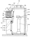
次に本発明に係る密閉容器に応じた蓋開閉システムについて説明する。図7は概略構成を示す該システムの側断面図であり、図8は該システム101におけるポッド載置部、ドア、ポッド、及び蓋等を同様の様式にて拡大して示した図である。また、図9はポッドの開口を蓋が閉鎖した状態での、ポッド載置部、ドア等を模式的に示す図である。蓋開閉システム101は、微小空間103を構成する筐体105及び筐体105に隣接して配置されるポッド載置部121を有する。筐体105は、更にファン107、ロボット109、第一の開口部111、第二の開口部113、ドアシステム115を有する。ファン107は筐体105によって微小空間103の上部に配置され、筐体105の外部空間に存在する気体を微小空間内部に導入する。なお、ファン107に対しては、外部空間の清浄度に応じて、当該空間から導入される気体より塵埃等の汚染物質を除去するフィルタが付随している。筐体105の下部には気流が流出可能となるような構造が配置されており、微小空間103内部で発生する粉塵等は当該気流に運ばれて筐体105の下部から外部空間に排出される。
Next, the lid opening / closing system corresponding to the sealed container according to the present invention will be described. FIG. 7 is a side sectional view of the system showing a schematic configuration, and FIG. 8 is an enlarged view of a pod mounting portion, a door, a pod, a lid and the like in the
ロボット109におけるロボットアーム109aは、第一の開口部111及び第二の開口部113を介して微小空間の外部に突出可能となっている。第一の開口部111はドアシステム115におけるドア115aにより一見閉鎖状態とされるが、ドア115aの外周と第一の開口部111の内周面との間には隙間が形成されることから、当該ドア115aは第一の開口部111を略閉鎖可能となっていると述べる。第二の開口部113は、ウエハ処理装置117の内部と接続されているが、当該ウエハ処理装置117の詳細に関しては本発明と直接の関係を有さないために本明細書における説明は省略する。また、ラッチ機構駆動機構131及びフランジカバー133については先に説明済みであることからここでの説明は省略することとし、図面の理解を容易とするために図中においてフランジカバー133を省略することとする。
The
ポッド載置部121は、ドッキングプレート123、ポッド固定システム125、及びドッキングプレート駆動システム127を有する。ドッキングプレート123の上面は略平面とされており、該上面にはポッド固定システム125の一部が配置される。本発明に係るポッド1は、ドッキングプレート123の上面に載置され、ポッド固定システム125の当該一部、具体的にはピンがポッド1の下面に配置された不図示の被係合部と係合することによりドッキングプレート123上の所定位置に固定される。なお、ドッキングプレート123は、ポッド1を上面に載置した際に、ポッド1における本体開口2aが前述した第一の開口部111と正対するよう配置されている。ドッキングプレート駆動システム127は、ガイドレール127a及び駆動シリンダ127bを用いて、ドッキングプレート123と共に該所定位置に固定されたポッド1を該第一の開口部111に向かう方向及び離間する方向に駆動する。
The
駆動用シリンダ127bは載置台本体121aに一端部が固定されており、他端部となる伸縮するシリンダ端部がドッキングプレート123に固定されている。ドッキングプレート123はガイドレール127aに対して摺動可能に支持されており、駆動シリンダ127bのシリンダ端部の伸縮に応じてガイドレール127a上を摺動する。ここで、ドッキングプレート123は、ポッド1を当該ドッキングプレート123上に外部から搭載する(ロードする)或いは取り除く(アンロードする)位置が微小空間103から最も離れた位置に存在することとなり、ポッドの蓋3を取り外す位置が微小空間103に対して最も接近する位置となる。
One end of the driving
ドア115aの表面に配置される吸着パッド115kは該蓋3と当接した状態で不図示の配管を通じて負圧供給源108(図10参照)より負圧を供給することにより該蓋3を吸着し、当該蓋3をドア115aによって保持することを可能とする。ドアシステム115は、ドアアーム115b、ドア開閉アクチュエータ115c及びドア上下機構115dを有する。ドアアーム115bは棒状の部材からなり、一端においてドア115aを支持し、他端においてドア開閉アクチュエータ115cと連結されており、中間部の適当な位置において当該位置を中心に回転可能に軸支されている。ドア開閉アクチュエータ115cによって該回転中心を軸としてドアアーム115bは回転し、該ドアアーム115bの一端及びここに支持されるドア115aは第一の開口部111に対して接近或いは離間の動作を行う。ドア上下機構115dは、ドア開閉アクチュエータ115cと前述したドアアーム115bの回転軸とを支持し、上下動用アクチュエータによって上下方向に延在するガイドに沿って当該アクチュエータ及びこれに支持されるドアアーム115b及びドア115aを上下方向に駆動する。
The
また、図9に示されるように、ドア115aの蓋3との対向面の周囲には、蓋3の表面3b設けられたシール面と対応するように、略円環状のシール部材115mが配置される。当該シール部材115mは、蓋3がドア115aの表面に配置された吸着パッド115kにより吸着保持された状態でシール面3cと当接、密着する。これにより形成される密閉空間に蓋3の表面に付着した微小な塵等を封止することで、これら塵の周囲への拡散を防止する。なお、本実施形態では蓋3は吸着パッド115kによってのみ保持されている。しかし、例えばドア表面に更なる吸着排気用のポートを設け、シール部材115mによって密閉されたドア115a、蓋3及びシール部材115mから構成される空間内部を排気する構成としても良い。当該構成とすることにより、微小な塵等を強制的に排除することが可能となると共に、ドア115aによる蓋3を保持する保持力をより大きなものとすることが可能となる。また、吸着パッド115kを無くし、シール部材115mを一種の吸着パッドとして使用することとしても良い。
Further, as shown in FIG. 9, a substantially
なお、図10に当該FIMSシステム101の構成をブロック図として示す。上述したファン107、ロボット109、ドアシステム115、ポッド固定システム125、及びドッキングプレート駆動システム127は、制御装置102によって各々制御される。ドアシステム115は、ドア開閉用アクチュエータ115c、及びドア上下機構115dを各々独立して制御可能であるが、実際上はこれら各々の構成が一連のタイムチャートに応じて動作するようにこれら構成を制御する。また、ラッチ機構駆動ユニット131についても制御装置102によって制御され、上述したドアシステム115の一連の動作と連動するように駆動される。なお、吸着パッド115kに対する負圧供給源108からの負圧の供給及び供給停止(負圧の破壊)の動作は、制御装置102によって行われる。ドッキングプレート駆動システム127は、駆動シリンダ127bの駆動のオンオフを行うが、当該駆動シリンダ127の動作によってドッキングプレート123が確実に所定の二位置、即ちポッド1のロード位置に存在する場合とポッド1がウエハ挿脱可能な位置であるドック位置に存在する場合とを検知する必要がある。
FIG. 10 is a block diagram showing the configuration of the
このため、ポッド1がドッキングプレート123上の載置されたこと、及びドッキングプレート123に対してポッド1をロード・アンロードすべき位置に該ドッキングプレート123が存在することを検知するロードセンサ127dが、ドッキングプレート駆動システム127に接続されている。また、ドッキングプレート123が上述したドック位置に存在するか否かを検知するドックセンサ127cも該ドッキングプレート駆動システム127に接続されている。ここで、本発明では、蓋3自体の剛性が高く変形しにくいこと、及びラッチ機構5が一軸のみの動作によって係合非係合の切換が為されることにより、当該ラッチ機構5の係合ミスが起こる蓋然性は従来構成と比較して大幅に低減されている。このため、本実施形態では、ラッチ機構駆動機構131に対して、ロッドの伸縮の状態に応じてオンオフの信号を発する構成とし、当該オンオフ信号によって蓋3のポッド本体2に対する係合、非係合の状態を検知することとしている。なお、本発明の実施形態は当該検知様式に限定されず、例えば光センサ等を用いて、ラッチ機構5の動作を直接的に検知して係合状態の適否を知る構成としても良い。
For this reason, the
ここで、実際にウエハ処理作業を行う際の当該蓋開閉システム101の動作について説明する。ウエハ処理作業において、所定枚数のウエハを収容し内部が清浄気体によって満たされたポッド1がドッキングプレート123上に載置される。ドッキングプレート123を載置する際に、ポッド固定システム125が動作してドッキングプレート123に対するポッド1の載置位置を所定のものとする。続いてドッキングプレート駆動システム127が動作し、ポッド1を第一の開口部111に向けて駆動する。具体的には、ポッド固定システム125によってドッキングプレート123と一体化されたポッド1を、ドッキングプレート123を介する様式にて駆動シリンダ127bが移動させる。その際、ドア115aは第一の開口部111を略閉鎖する位置で停止している。当該駆動動作は、ポッド1の蓋3がドア115aの当接面と当接し、ドッキングプレート123と第一の開口部111と所定の位置関係となった段階にて終了する。この時、ラッチ機構駆動ユニット131とラッチ機構5とが図6A等に示す所定の位置関係を満たす状態となる。当該状態からラッチ機構駆動ユニット131が動作を開始し、ポッド本体2の蓋3に対する係合状態が解除される。同時に、吸着パッド115kが蓋3を吸着し、蓋3がドア115aによって保持され、且つ蓋3の表面とドア115aの表面とに挟持される空間がシール部材115mによって密閉された状態となる。
Here, the operation of the lid opening /
当該状態からドア開閉アクチュエータ115cが動作を開始し、ドアアーム115bが回動して蓋3を保持するドア115aを第一の開口部111から微小空間103の内部方向に運ぶ。ドアアーム115bが所定角度で回動を停止した後、ドア上下機構115dが動作を開始し、ドア開閉アクチュエータ115cと共にドア115aを下方に移動させる。当該動作によって第一の開口部111は全開状態となり、微小空間103は第一の開口部111を介してポッド本体2の内部と連通した状態となる。この状態においてロボット109が動作を開始し、ロボットアーム109aによってウエハ4をポッド1の内部から第二の開口部113を介してウエハ処理装置117に搬送する。また、この状態を維持して、当該ロボット109は、更にウエハ処理装置117内部において所定の処理が施されたウエハをポッド1内部へも搬送する。蓋3をポッド1に取り付け、ポッド1を蓋開閉システム101より取り外し可能とする場合には、基本的にはこれら動作が逆に行われる。
From this state, the door opening /
以上に述べたポッド、及び当該ポッドに対応する蓋開閉システムたるFIMSシステムを用いることにより、ポッド開口を閉鎖する蓋の表面に付着する極微小な塵の影響を抑制し、且つ蓋開閉時において当該開閉操作に伴う塵の発生、及び発生した塵の微小空間或いはポッド内部への拡散を抑制することが可能となる。より具体的には、蓋3のポッド本体2への固定及びその解除をポッド本体に設けられたフランジ部2cの外側面側行うこととしている。例えば第一の開口部111の外周近傍から外部空間に向かう気流を形成しておくことによって、配置的に低減されているポッド内或いは微小空間内への微小な塵等の拡散可能性を更に低減することが可能となる。
By using the pod described above and the FIMS system that is a lid opening / closing system corresponding to the pod, the influence of extremely fine dust adhering to the surface of the lid that closes the pod opening is suppressed, and when the lid is opened and closed It is possible to suppress the generation of dust accompanying the opening / closing operation and the diffusion of the generated dust into the minute space or inside the pod. More specifically, the
以上述べた実施形態では、本発明はウエハを対象とするFIMSシステムに関して主として述べている。しかしながら、本発明の適用対象は該システムに限定されず、例えばディスプレイ用のパネル、光ディスク等を収容する密閉容器等に対しても適用可能である。 In the embodiments described above, the present invention is mainly described with respect to the FIMS system for wafers. However, the application target of the present invention is not limited to the system, and can be applied to, for example, a sealed container that accommodates a display panel, an optical disk, or the like.
1:ポッド、 2:ポッド本体、 3:蓋、 4:ウエハ、 5:ラッチ機構、 101:蓋開閉システム、 102:制御装置、 103:微小空間、 105:筐体、 107:ファン、 108:負圧供給源 109:ロボット、 111:第一の開口部、 113:第二の開口部、 115:ドアシステム、 117:ウエハ処理装置、 121:ポッド載置台、 123:ドッキングプレート、 125:ポッド固定システム、 127:ドッキングプレート駆動システム、 131:ラッチ部材駆動ユニット、 131:フランジカバー 1: Pod, 2: Pod body, 3: Lid, 4: Wafer, 5: Latch mechanism, 101: Lid opening / closing system, 102: Control device, 103: Micro space, 105: Housing, 107: Fan, 108: Negative Pressure supply source 109: Robot, 111: First opening, 113: Second opening, 115: Door system, 117: Wafer processing apparatus, 121: Pod mounting table, 123: Docking plate, 125: Pod fixing system 127: Docking plate drive system 131: Latch member drive unit 131: Flange cover
Claims (12)
被収容物を収容可能な内部空間と、前記内部空間と外部空間とを連通させると共に前記蓋における前記平板形状の一面によって閉鎖される開口と、前記開口の周囲より開口形成面に平行に張り出し且つ前記開口を閉鎖した状態にある前記蓋を収容する収容空間を構成するフランジ部と、前記蓋を前記収容空間に収容した状態において前記被係合部に対応する位置に配置される前記フランジ部の外面から前記収容空間に連通する挿通孔と、を有する容器本体部と、
前記開口形成面に平行な一軸に沿って移動可能であって前記一軸の方向に延在するラッチ本体部と、前記ラッチ本体部から前記一軸の延在方向と異なる方向に突出する連結部と、前記連結部先端に配置される係合部とを有するラッチ機構と、を有し、
少なくとも前記係合部は前記挿通孔から前記収容空間内に至り、
前記係合部は前記収容空間内に配置される前記蓋の前記被係合部に係合し、
前記本体部が前記一軸に沿って移動することによって前記係合部と前記被係合部との係合及び係合の解除とが為されることを特徴とする密閉容器。 A lid having a flat plate shape and having an engaged portion provided in the flat plate shape;
An internal space capable of accommodating an object to be accommodated, an opening that communicates the internal space and the external space and is closed by one surface of the flat plate shape in the lid, and extends in parallel to an opening forming surface from the periphery of the opening; A flange portion constituting an accommodation space for accommodating the lid in a state in which the opening is closed, and a flange portion arranged at a position corresponding to the engaged portion in a state in which the lid is accommodated in the accommodation space. A container body having an insertion hole communicating from the outer surface to the accommodation space;
A latch body that is movable along one axis parallel to the opening forming surface and extends in the direction of the one axis; and a connecting part that protrudes from the latch body in a direction different from the extending direction of the one axis; A latch mechanism having an engaging portion disposed at the distal end of the connecting portion,
At least the engaging portion reaches the accommodating space from the insertion hole,
The engaging portion engages with the engaged portion of the lid disposed in the accommodating space,
An airtight container in which the engagement portion and the engaged portion are engaged and released by moving the main body portion along the one axis.
前記係合部は前記L字形状の第一の直線部を構成する内側壁と係合可能であって、前記本体部が前記一軸に沿って移動することによって前記係合部が前記第二の直線部に移動することにより係合状態が解除されることを特徴とする請求項1に記載の密閉容器。 The engaged portion has a first straight portion extending along an extending direction of the outer peripheral surface of the flat plate shape, and an opening end on one surface side of the flat plate shape, and in the thickness direction of the lid. It consists of an L-shape that includes a second straight portion that extends,
The engaging portion is engageable with an inner wall constituting the L-shaped first linear portion, and the engaging portion is moved along the one axis to move the engaging portion to the second axis. The closed container according to claim 1, wherein the engaged state is released by moving to the linear portion.
開口部を有する微小空間と、
前記開口部を略閉鎖する位置と開放する位置との間で移動可能なドアと、
前記密閉容器が前記ドアによる前記蓋の開閉が行われる位置に存在した際に前記ラッチ機構を操作可能であって、前記開口部の周囲に配置されるラッチ機構駆動手段と、を有することを特徴とする蓋開閉システム。 A lid opening / closing system capable of opening and closing the lid with respect to the sealed container according to any one of claims 1 to 8 and allowing the contained object to be inserted into and removed from the sealed container.
A minute space having an opening;
A door movable between a position where the opening is substantially closed and a position where the opening is opened;
Latch mechanism driving means arranged to be able to operate the latch mechanism when the sealed container is present at a position where the lid is opened and closed by the door, and arranged around the opening. Lid opening and closing system.
前記ラッチ機構駆動手段は、前記容器載置台の移動により前記容器載置台に対して相対移動可能なカム面と、前記容器載置台に配置された前記カム面に従動可能なカム手段とによって構成されて前記容器載置台の移動に伴う前記カム面の変化に準じて前記ラッチ機構に対して押圧力を付与するカム機構を有することを特徴とする請求項9に記載の蓋開閉システム。 A container mounting table for moving the closed container closer to or away from the opening in a state where the closed container is mounted;
The latch mechanism driving means includes a cam surface that can move relative to the container mounting table by movement of the container mounting table, and a cam means that can follow the cam surface disposed on the container mounting table. The lid opening / closing system according to claim 9, further comprising a cam mechanism that applies a pressing force to the latch mechanism according to a change in the cam surface accompanying the movement of the container mounting table.
Priority Applications (1)
| Application Number | Priority Date | Filing Date | Title |
|---|---|---|---|
| JP2009006602A JP4732524B2 (en) | 2008-09-08 | 2009-01-15 | Sealed container and lid opening / closing system of the sealed container |
Applications Claiming Priority (3)
| Application Number | Priority Date | Filing Date | Title |
|---|---|---|---|
| JP2008229238 | 2008-09-08 | ||
| JP2008229238 | 2008-09-08 | ||
| JP2009006602A JP4732524B2 (en) | 2008-09-08 | 2009-01-15 | Sealed container and lid opening / closing system of the sealed container |
Related Child Applications (1)
| Application Number | Title | Priority Date | Filing Date |
|---|---|---|---|
| JP2011093561A Division JP5263633B2 (en) | 2008-09-08 | 2011-04-20 | Sealed container and lid opening / closing system of the sealed container |
Publications (2)
| Publication Number | Publication Date |
|---|---|
| JP2010087455A true JP2010087455A (en) | 2010-04-15 |
| JP4732524B2 JP4732524B2 (en) | 2011-07-27 |
Family
ID=42251080
Family Applications (2)
| Application Number | Title | Priority Date | Filing Date |
|---|---|---|---|
| JP2009006602A Active JP4732524B2 (en) | 2008-09-08 | 2009-01-15 | Sealed container and lid opening / closing system of the sealed container |
| JP2011093561A Active JP5263633B2 (en) | 2008-09-08 | 2011-04-20 | Sealed container and lid opening / closing system of the sealed container |
Family Applications After (1)
| Application Number | Title | Priority Date | Filing Date |
|---|---|---|---|
| JP2011093561A Active JP5263633B2 (en) | 2008-09-08 | 2011-04-20 | Sealed container and lid opening / closing system of the sealed container |
Country Status (1)
| Country | Link |
|---|---|
| JP (2) | JP4732524B2 (en) |
Cited By (6)
| Publication number | Priority date | Publication date | Assignee | Title |
|---|---|---|---|---|
| US20100059408A1 (en) * | 2008-09-08 | 2010-03-11 | Tdk Corporation | Closed container and lid opening/closing system therefor |
| US20100117377A1 (en) * | 2008-11-11 | 2010-05-13 | Tdk Corporation | Closed container and lid opening/closing system therefor |
| JP2010108998A (en) * | 2008-10-28 | 2010-05-13 | Shin Etsu Polymer Co Ltd | Substrate storage container |
| US20100133270A1 (en) * | 2008-11-28 | 2010-06-03 | Tdk Corporation | Lid opening/closing system for closed container |
| US20110215028A1 (en) * | 2010-03-08 | 2011-09-08 | Tdk Corporation | Substrate storage pod and lid opening/closing system for the same |
| KR102346007B1 (en) * | 2020-09-14 | 2022-01-03 | 김진국 | Food Waste Processing Product |
Citations (5)
| Publication number | Priority date | Publication date | Assignee | Title |
|---|---|---|---|---|
| JPH11145269A (en) * | 1997-11-11 | 1999-05-28 | Starlite Co Ltd | Sealed substrate cassette and manufacturing device, using the same |
| JP2000255677A (en) * | 1999-03-11 | 2000-09-19 | Toshiba Corp | Substrate storing container and method for opening or closing lid for substrate storing container |
| JP2001077177A (en) * | 1999-06-28 | 2001-03-23 | Tokyo Electron Ltd | Lid mounting/dismounting device for wafer carrier and load port device |
| JP2003174080A (en) * | 2001-12-04 | 2003-06-20 | Kakizaki Mamufacuturing Co Ltd | Container for housing/storing thin plate |
| JP2003297896A (en) * | 2002-03-29 | 2003-10-17 | Hitachi Kokusai Electric Inc | Semiconductor manufacturing apparatus |
Family Cites Families (1)
| Publication number | Priority date | Publication date | Assignee | Title |
|---|---|---|---|---|
| JP2004235516A (en) * | 2003-01-31 | 2004-08-19 | Trecenti Technologies Inc | Purging method in wafer housing jig, load port, and method for manufacturing semiconductor device |
-
2009
- 2009-01-15 JP JP2009006602A patent/JP4732524B2/en active Active
-
2011
- 2011-04-20 JP JP2011093561A patent/JP5263633B2/en active Active
Patent Citations (5)
| Publication number | Priority date | Publication date | Assignee | Title |
|---|---|---|---|---|
| JPH11145269A (en) * | 1997-11-11 | 1999-05-28 | Starlite Co Ltd | Sealed substrate cassette and manufacturing device, using the same |
| JP2000255677A (en) * | 1999-03-11 | 2000-09-19 | Toshiba Corp | Substrate storing container and method for opening or closing lid for substrate storing container |
| JP2001077177A (en) * | 1999-06-28 | 2001-03-23 | Tokyo Electron Ltd | Lid mounting/dismounting device for wafer carrier and load port device |
| JP2003174080A (en) * | 2001-12-04 | 2003-06-20 | Kakizaki Mamufacuturing Co Ltd | Container for housing/storing thin plate |
| JP2003297896A (en) * | 2002-03-29 | 2003-10-17 | Hitachi Kokusai Electric Inc | Semiconductor manufacturing apparatus |
Cited By (10)
| Publication number | Priority date | Publication date | Assignee | Title |
|---|---|---|---|---|
| US20100059408A1 (en) * | 2008-09-08 | 2010-03-11 | Tdk Corporation | Closed container and lid opening/closing system therefor |
| US8528947B2 (en) * | 2008-09-08 | 2013-09-10 | Tdk Corporation | Closed container and lid opening/closing system therefor |
| JP2010108998A (en) * | 2008-10-28 | 2010-05-13 | Shin Etsu Polymer Co Ltd | Substrate storage container |
| US20100117377A1 (en) * | 2008-11-11 | 2010-05-13 | Tdk Corporation | Closed container and lid opening/closing system therefor |
| US8322759B2 (en) * | 2008-11-11 | 2012-12-04 | Tdk Corporation | Closed container and lid opening/closing system therefor |
| US20100133270A1 (en) * | 2008-11-28 | 2010-06-03 | Tdk Corporation | Lid opening/closing system for closed container |
| US8657346B2 (en) * | 2008-11-28 | 2014-02-25 | Tdk Corporation | Lid opening/closing system for closed container |
| US20110215028A1 (en) * | 2010-03-08 | 2011-09-08 | Tdk Corporation | Substrate storage pod and lid opening/closing system for the same |
| US8876173B2 (en) * | 2010-03-08 | 2014-11-04 | Tdk Corporation | Substrate storage pod and lid opening/closing system for the same |
| KR102346007B1 (en) * | 2020-09-14 | 2022-01-03 | 김진국 | Food Waste Processing Product |
Also Published As
| Publication number | Publication date |
|---|---|
| JP2011151417A (en) | 2011-08-04 |
| JP5263633B2 (en) | 2013-08-14 |
| JP4732524B2 (en) | 2011-07-27 |
Similar Documents
| Publication | Publication Date | Title |
|---|---|---|
| JP4624458B2 (en) | Sealed container and lid opening / closing system of the sealed container | |
| JP4919123B2 (en) | Processing substrate storage pod and lid opening / closing system of processing substrate storage pod | |
| JP4748816B2 (en) | Closed container lid opening and closing system | |
| US8528947B2 (en) | Closed container and lid opening/closing system therefor | |
| JP5263633B2 (en) | Sealed container and lid opening / closing system of the sealed container | |
| US8171964B2 (en) | Apparatus and method for opening/closing lid of closed container, gas replacement apparatus using same, and load port apparatus | |
| JP5532861B2 (en) | Closed container lid closing method and sealed container lid opening / closing system | |
| JP4877662B2 (en) | Sealed container and lid opening / closing system of the sealed container | |
| JP5729148B2 (en) | Opening / closing device for substrate transfer container, opening / closing device for lid and semiconductor manufacturing device | |
| TW202017821A (en) | Load port | |
| KR102602264B1 (en) | Load port apparatus and method of driving the same | |
| JP2010040912A (en) | System for opening and closing sealed container lid, and method for opening and closing lid | |
| JP2009135205A (en) | Container lid opening/closing system and substrate processing method using the same | |
| JP2002076093A (en) | Foup opener | |
| JP6274379B1 (en) | Load port and wafer transfer method | |
| US9401295B2 (en) | Load port apparatus and clamping device to be used for the same | |
| JP2010034146A (en) | Sealed container, and lid opening/closing system of sealed container | |
| KR102536621B1 (en) | Substrate processing apparatus and substrate processing system | |
| JP2010056296A (en) | System and method for opening/closing lid of sealed vessel | |
| JP3917138B2 (en) | Pod clamp unit of pod opener, pod clamp mechanism and clamping method using the pod clamp unit | |
| JP2004311863A (en) | Opening/closing mechanism for substrate processing equipment |
Legal Events
| Date | Code | Title | Description |
|---|---|---|---|
| A621 | Written request for application examination |
Free format text: JAPANESE INTERMEDIATE CODE: A621 Effective date: 20100222 |
|
| A977 | Report on retrieval |
Free format text: JAPANESE INTERMEDIATE CODE: A971007 Effective date: 20110324 |
|
| TRDD | Decision of grant or rejection written | ||
| A01 | Written decision to grant a patent or to grant a registration (utility model) |
Free format text: JAPANESE INTERMEDIATE CODE: A01 Effective date: 20110330 |
|
| A01 | Written decision to grant a patent or to grant a registration (utility model) |
Free format text: JAPANESE INTERMEDIATE CODE: A01 |
|
| A61 | First payment of annual fees (during grant procedure) |
Free format text: JAPANESE INTERMEDIATE CODE: A61 Effective date: 20110420 |
|
| FPAY | Renewal fee payment (event date is renewal date of database) |
Free format text: PAYMENT UNTIL: 20140428 Year of fee payment: 3 |
|
| R150 | Certificate of patent or registration of utility model |
Ref document number: 4732524 Country of ref document: JP Free format text: JAPANESE INTERMEDIATE CODE: R150 Free format text: JAPANESE INTERMEDIATE CODE: R150 |
|
| FPAY | Renewal fee payment (event date is renewal date of database) |
Free format text: PAYMENT UNTIL: 20140428 Year of fee payment: 3 |