JP2010040912A - System for opening and closing sealed container lid, and method for opening and closing lid - Google Patents
System for opening and closing sealed container lid, and method for opening and closing lid Download PDFInfo
- Publication number
- JP2010040912A JP2010040912A JP2008204157A JP2008204157A JP2010040912A JP 2010040912 A JP2010040912 A JP 2010040912A JP 2008204157 A JP2008204157 A JP 2008204157A JP 2008204157 A JP2008204157 A JP 2008204157A JP 2010040912 A JP2010040912 A JP 2010040912A
- Authority
- JP
- Japan
- Prior art keywords
- opening
- fixing
- pod
- lid
- container
- Prior art date
- Legal status (The legal status is an assumption and is not a legal conclusion. Google has not performed a legal analysis and makes no representation as to the accuracy of the status listed.)
- Granted
Links
Images


Abstract
Description
本発明は、半導体製造プロセス等において、ポッドと呼ばれる搬送容器に内部保持されたウエハを半導体処理装置間にて移送する際に用いられる、所謂FIMS(Front-Opening Interface Mechanical Standard)システムに関する。より詳細には、当該FIMSシステムにおいて用いられる、ウエハを収容する密閉容器たる所謂FOUP(Front-Opening Unified Pod)と呼ばれるポッドの蓋を開閉して該ポッドに対するウエハの移載を行うFIMSシステムたる蓋開閉システム及び当該システムを用いた蓋開閉方法に関する。 The present invention relates to a so-called FIMS (Front-Opening Interface Mechanical Standard) system used when a wafer internally held in a transfer container called a pod is transferred between semiconductor processing apparatuses in a semiconductor manufacturing process or the like. More specifically, a lid that is used in the FIMS system is a FIMS system that opens and closes a so-called FOUP (Front-Opening Unified Pod), which is a sealed container that contains a wafer, and transfers the wafer to the pod. The present invention relates to an opening / closing system and a lid opening / closing method using the system.
近年、半導体製造プロセスは、処理装置内部、ポッド(ウエハの収容容器)、及び当該ポッドから処理装置への基板受け渡しを行う微小空間のみを高清浄状態に保持し、その他の空間の清浄度はある程度のレベルに維持して行われている。ポッドは、その内部に複数のウエハを平行且つ隔置した状態で保持可能な棚と、外面を構成する面の一つにウエハ出し入れに用いられる開口とを有する略立方体形状を有する本体と、その開口を閉鎖する蓋とから構成される。この開口が形成されている面がポッドの底面ではなく一側面(微小空間に対して正対する面)に位置するポッドを前述したFOUPと総称している。 In recent years, the semiconductor manufacturing process keeps the inside of a processing apparatus, a pod (wafer container), and a very small space for transferring a substrate from the pod to the processing apparatus in a highly clean state, and the cleanliness of other spaces is to some extent. Has been done to maintain the level. The pod has a substantially cubic body having a shelf that can hold a plurality of wafers in parallel and spaced apart from each other, and an opening used for loading and unloading the wafer on one of the surfaces constituting the outer surface. And a lid that closes the opening. The pod where the opening is formed is not the bottom surface of the pod but on one side surface (the surface facing the minute space) and is collectively referred to as FOUP.
また、上述した微小空間は、ポッドの開口と向かい合う開口部と、開口部を閉鎖するドアと、半導体処理装置側に設けられた処理装置側の他の開口部と、開口部からポッド内部に侵入してウエハを保持すると共に該処理装置側の他の開口部を通過して処理装置側にウエハを搬送する移載ロボットとを有している。また、微小空間を形成する構成は、ドア正面にポッド開口が正対するようポッドを支持する載置台を有している。この載置台の上面には、ポッド下面に設けられた位置決め用の穴に嵌合されてポッドの載置位置を規定する位置決めピンと、ポッド下面に設けられた被クランプ部と係合してポッドを載置台に対して固定するクランプユニットとが配置されている。通常、載置台はドア方向に対して所定距離の前後移動が可能となっている。ポッド内のウエハを処理装置に移載する際には、ポッドが載置された状態でポッドの蓋がドアと接触するまでポッドを移動させ、接触後にドアによってポッド開口部からその蓋が取り除かれる。これら操作によって、ポッド内部と処理装置内部とが微小空間を介して連通することとなり、以降ウエハの移載操作が繰り返して行われる。この載置台、ドア、開口部、ドアの開閉機構、開口部が構成された微小空間の一部を構成する壁等を含めて、前述したFIMSシステムと総称される。 In addition, the above-described minute space enters the inside of the pod through the opening facing the opening of the pod, the door for closing the opening, the other opening on the side of the processing apparatus provided on the semiconductor processing apparatus side, and the opening. And a transfer robot that holds the wafer and passes the other opening on the processing apparatus side to convey the wafer to the processing apparatus side. Moreover, the structure which forms minute space has the mounting base which supports a pod so that a pod opening may face in front of a door. On the upper surface of the mounting table, a positioning pin that is fitted into a positioning hole provided on the lower surface of the pod and defines the mounting position of the pod, and a clamped portion provided on the lower surface of the pod are engaged with the pod. A clamp unit that is fixed to the mounting table is disposed. Usually, the mounting table can move back and forth a predetermined distance with respect to the door direction. When the wafer in the pod is transferred to the processing apparatus, the pod is moved with the pod being placed until the lid of the pod comes into contact with the door, and after the contact, the lid is removed from the pod opening by the door. . By these operations, the inside of the pod and the inside of the processing apparatus communicate with each other through a minute space, and the wafer transfer operation is repeated thereafter. The mounting table, the door, the opening, the opening / closing mechanism of the door, the wall that forms part of the minute space in which the opening is configured, and the like are collectively referred to as the FIMS system described above.
前述したポッド固定用のクランプユニットとしては、例えば特許文献1或いは2に開示される構成等が知られている。これらクランプユニットは、ポッド下面に配置された被クランプ部をクランプし、下方に付勢することによってポッドを載置台に対して固定している。ここで、ポッドは主として樹脂等の素材により形成されることが多く、機械的は負荷が大きい場合には変形する可能性が存在する。また、通常被クランプ部の形成部位に対しては特に補強等施されていないことから、従来はこの機械的な負荷の大きさを適当なものとする等の対策が為されていた。しかしながら、昨今のウエハ等基板の大径化に伴ってポッドのサイズが大型化し、十分なクランプ力を被クランプ部に加えることとポッドの変形を抑制することとの両立が難しくなってきている。
As the pod fixing clamp unit described above, for example, a configuration disclosed in
また、ポッドの載置位置を規定する位置決めピンとしては特許文献3に開示する構成が知られている。例えば、載置台上に位置決めピンとは異なる突起を配置し、被クランプ部を当該突起によって支持することにより、変形を抑制する方法も考えられる。しかし、この様な突起の存在は位置決めピンの作用の妨げとなり、実際的な対応策とはなり得ない。また、ポッドサイズが大きくなりその重量も大きくなった場合、例えば一の位置決めピンがポッドにおける位置決め用の穴に対して適切に嵌合していない場合であっても、ポッドの重量によって当該穴の構成面と位置決めピンとが摺動せず、そのままの状態を保つ場合が起こり得る。このような場合に従来のような方式のクランプユニットによるポッドの固定を為そうとした場合、ポッドに加えられる負荷及び当該負荷により生じる変形はより大きくなると考えられる。 Further, a configuration disclosed in Patent Document 3 is known as a positioning pin that defines the placement position of the pod. For example, a method of suppressing deformation by arranging a projection different from the positioning pin on the mounting table and supporting the clamped portion by the projection is also conceivable. However, the presence of such protrusions hinders the action of the positioning pin and cannot be a practical countermeasure. Also, when the pod size is increased and its weight is increased, for example, even when one positioning pin is not properly fitted to the positioning hole in the pod, the weight of the pod There may be a case where the component surface and the positioning pin do not slide and remain as they are. In such a case, when it is attempted to fix the pod with a conventional type clamp unit, it is considered that the load applied to the pod and the deformation caused by the load become larger.
本発明は以上の状況に鑑みて為されたものであり、大型化したポッドであっても、載置台に対して固定した状態においてポッドに対して変形を与えない蓋開閉システム、及びポッドの位置決め凹部と載置台上の位置決めピンとを常に適切な位置関係として、ポッドを載置台に対して適切に位置決めしてこれを固定保持することを可能とする蓋開閉方法の提供を目的としている。 The present invention has been made in view of the above circumstances, and a lid opening / closing system that does not deform a pod even when the pod is enlarged with respect to the mounting table, and positioning of the pod It is an object of the present invention to provide a lid opening / closing method capable of appropriately positioning a pod with respect to the mounting table and fixing and holding the pod with the appropriate positional relationship between the recess and the positioning pin on the mounting table.
上記課題を解決するために、本発明に係る蓋開閉システムは、蓋と蓋により閉鎖される開口を一側面に有すると共に内部に被収容物を収容可能な密閉容器に対して蓋を開閉して密閉容器内部への被収容物の挿脱を可能とする蓋開閉システムであって、第一の開口部を有する微小空間と、第一の開口部を閉鎖する位置と開放する位置との間で移動可能なドアと、第一の開口部に対して開口が正対するように密閉容器を載置可能なドッキングプレートと、を有し、ドッキングプレートは密閉容器を固定する密閉容器固定システム、及び密閉容器に設けられた位置決め凹部に嵌合して密閉容器のドッキングプレートに対する位置決めを為す位置決めピン、を有し、密閉容器を前記ドッキングプレートに対して固定するために密閉容器固定システムが呈する固定力は、固定力に起因する密閉容器の変形に対して位置決めピンが変形を抑制する抗力を発生可能となるように固定力の作用線が配置されることを特徴としている。 In order to solve the above-described problems, a lid opening / closing system according to the present invention has a lid and an opening that is closed by the lid on one side and opens and closes the lid with respect to a sealed container that can accommodate an object to be contained therein. A lid opening / closing system that enables insertion / removal of an object to be contained in a sealed container, between a minute space having a first opening, and a position at which the first opening is closed and a position at which the first opening is opened. A movable door, and a docking plate on which the sealed container can be placed so that the opening faces the first opening, and the docking plate fixes the sealed container, and the sealing A sealed pin fixing system for fixing the sealed container to the docking plate, and a positioning pin for positioning the sealed container with respect to the docking plate by fitting in a positioning recess provided in the container; Fixing force is characterized in that the line of action of the fixing force is arranged so as locating pins to deformation of the sealed container due to the fixing force is capable of generating a suppressing drag deformation.
なお、前述した蓋開閉システムにおいて、固定力の作用線は、位置決めピンの軸線と一致することが好ましい。また、密閉容器固定システムは収容容器下面に密着可能な吸着パッドを有し、位置決めピンは吸着パッド内部に配置されることが好ましい。 In the lid opening / closing system described above, it is preferable that the line of action of the fixing force coincides with the axis of the positioning pin. Moreover, it is preferable that the closed container fixing system has a suction pad that can be in close contact with the lower surface of the storage container, and the positioning pin is disposed inside the suction pad.
また、上記課題を解決するために、本発明に係る蓋開閉方法は、蓋と蓋により閉鎖される開口を一側面に有すると共に内部に被収容物を収容可能な密閉容器に対して蓋を開閉して密閉容器内部への被収容物の挿脱を可能とする蓋開閉システムにおいて、密閉容器より蓋を除去或いは取り付けを為して開口を開閉する蓋開閉方法であって、蓋開閉装置は第一の開口部を有する微小空間と、第一の開口部を閉鎖する位置と開放する位置との間で移動可能なドアと、第一の開口部に対して開口が正対するように密閉容器を載置可能なドッキングプレートと、を有し、ドッキングプレートは密閉容器を固定する複数の密閉容器固定システム、及び密閉容器に設けられた位置決め凹部に嵌合して密閉容器のドッキングプレートに対する位置決めを為す密閉容器固定システムに応じた複数の位置決めピン、を有し、密閉容器を前記ドッキングプレートに対して固定するために密閉容器固定システムが呈する固定力は、固定力に起因する密閉容器の変形に対して各々対応する位置決めピンが変形を抑制する抗力を発生可能となるように固定力の作用線が配置され、蓋開閉方法は、ドッキングプレート上に密閉容器を載置し、位置決め凹部に対して位置決めピンが略嵌合し、固定力が複数の密閉容器固定システム各々より順次発生されることを特徴としている。 In order to solve the above problems, a lid opening / closing method according to the present invention opens and closes a lid with respect to a sealed container that has a lid and an opening that is closed by the lid on one side and that can accommodate an object to be contained therein. In the lid opening / closing system that enables insertion / removal of objects to be contained in the sealed container, a lid opening / closing method for opening / closing the opening by removing or attaching the lid from the sealed container. A minute space having one opening, a door movable between a position where the first opening is closed and a position where the first opening is opened, and a sealed container so that the opening faces the first opening. A docking plate that can be placed, and the docking plate is fitted with a plurality of sealed container fixing systems for fixing the sealed container, and a positioning recess provided in the sealed container to position the sealed container with respect to the docking plate. Dense The fixing force exhibited by the hermetic container fixing system for fixing the hermetic container to the docking plate has a plurality of positioning pins corresponding to the container fixing system, against the deformation of the hermetic container caused by the fixing force. The action line of the fixing force is arranged so that each corresponding positioning pin can generate a drag that suppresses deformation, and the lid opening / closing method is such that the hermetic container is placed on the docking plate and the positioning pin is positioned with respect to the positioning recess. Are substantially fitted, and a fixing force is sequentially generated from each of the plurality of closed container fixing systems.
なお、上述した蓋開閉方法において、密閉容器固定システムは収容容器下面に密着可能な吸着パッドを有し、位置決めピンは吸着パッド内部に配置され、密閉容器の固定に際し、複数の密閉容器固定システムの内、固定力を発生済みの密閉容器固定システム及び固定力を次に発生予定の密閉容器固定システム以外については、固定力とは逆の方向に作用する力が加えられることが好ましい。 In the lid opening / closing method described above, the closed container fixing system has a suction pad that can be in close contact with the lower surface of the storage container, and the positioning pin is disposed inside the suction pad. Among them, a force acting in the direction opposite to the fixing force is preferably applied except for the closed container fixing system in which the fixing force has been generated and the closed container fixing system in which the fixing force is to be generated next.
本発明によれば、位置決めピンによってポッドを支持する位置において、ポッドに対する固定力を作用させている。従って、ポッド底面に生じる曲げモーメントはごく小さく抑えられ、ポッドの変形を防止することが可能となる。また、本発明によれば、ポッドに対して固定力を加える位置は位置決めピンを受容する位置決め凹部の配置と位置している。通常このような位置決め凹部が存在する領域は、位置決めピンによる支持に耐えるために高い剛性が付与されている。従って、固定力がポッドにおける剛性の高い領域に対して付与されることとなり、固定力が比較的大きい場合であってもポッドの変形を効果的に抑制或いは防止することが可能となる。更に、本発明では、位置決めピンに対応して当該ピンの埋設方向に固定力が作用する。従って、ポッド載置時において位置決め凹部と位置決めピンとの位置関係が不適切な場合であっても、位置決め凹部がその中心に向かった凹む傾斜面を有することで、ポッド固定時の固定力の付与によりこれら位置関係の是正が為されるという効果を期待できる。 According to the present invention, the fixing force is applied to the pod at the position where the pod is supported by the positioning pin. Therefore, the bending moment generated on the bottom surface of the pod can be suppressed to be extremely small, and deformation of the pod can be prevented. Further, according to the present invention, the position where the fixing force is applied to the pod is positioned as the positioning recess for receiving the positioning pin. Usually, a region where such a positioning recess is present is given high rigidity to withstand the support by the positioning pin. Therefore, the fixing force is applied to the highly rigid region of the pod, and even when the fixing force is relatively large, the deformation of the pod can be effectively suppressed or prevented. Furthermore, in the present invention, a fixing force acts on the burying direction of the pin corresponding to the positioning pin. Therefore, even when the positional relationship between the positioning recess and the positioning pin is inappropriate when the pod is placed, the positioning recess has an inclined surface that is recessed toward the center, thereby providing a fixing force when fixing the pod. The effect of correcting these positional relationships can be expected.
また、本発明によれば、ポッドの固定に吸着パッドを用いることとして当該吸着パッドの中心に位置決めピンを埋設している。このため、位置決めピンとポッドとの接触点を中心としてその周囲を当該ピンの埋設方向に吸引、固定する固定力を作用させることとなる。従って、固定力が位置決めピンとポッドとの接触点に対して特定の方向に偏ることが防止され、ポッドと載置台との位置関係をより適切な状態としてポッドを固定することが可能となる。また、本発明によれば、複数の位置決めピンに応じた位置での固定力の付加を各々異なるタイミングにて実行することとしている。当該様式の操作を通じてポッドの固定を為すことにより、個々の固定力を付加する際に生じる微小な衝撃等により、仮に位置決めピン先端と位置決め凹部形成面とがかみ合った状態で位置ずれが生じていたとしても、これらを互いに摺動させて適切な位置関係を得ることが可能となる。 According to the present invention, the positioning pin is embedded at the center of the suction pad as the suction pad is used for fixing the pod. For this reason, a fixing force is applied to suck and fix the periphery of the contact point between the positioning pin and the pod in the embedding direction of the pin. Therefore, the fixing force is prevented from being biased in a specific direction with respect to the contact point between the positioning pin and the pod, and the pod can be fixed with the positional relationship between the pod and the mounting table being more appropriate. Further, according to the present invention, the application of the fixing force at the positions corresponding to the plurality of positioning pins is executed at different timings. By fixing the pod through the operation of the style, a position shift occurred in a state where the positioning pin tip and the positioning recess forming surface were engaged with each other due to a minute impact generated when each fixing force was applied. However, it is possible to obtain an appropriate positional relationship by sliding them together.
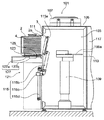
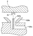
次に、本発明の一実施形態について、以下に図面を参照して説明する。図1は本発明の一実施形態に係る蓋開閉システムの側断面図であり、図2はポッドの開口を蓋が閉鎖した状態での該システム101におけるポッド載置部、ドア、ポッド、及び蓋等を同様の様式にて拡大して示した図である。また、更に図3は、当該蓋開閉システムおける主要部たる載置台を斜視図により示している。また、図4は図3に示すポッド固定手段及びその近傍の構成、及び対応するポッドの位置決め凹部及びその近傍を断面として示す図である。
Next, an embodiment of the present invention will be described below with reference to the drawings. FIG. 1 is a side sectional view of a lid opening / closing system according to an embodiment of the present invention, and FIG. 2 is a pod placement portion, door, pod, and lid in the
本発明に係る蓋開閉システムであるFIMSシステム101は、微小空間103を構成する筐体105及び筐体105に隣接して配置されるポッド載置部121を有する。筐体105は、更にファン107、ロボット109、第一の開口部111、第二の開口部113、ドアシステム115を有する。ファン107は筐体105によって微小空間103の上部に配置され、筐体105の外部空間に存在する気体を微小空間内部に導入する。筐体105の下部には気流が流出可能となるような構造が配置されており、微小空間103内部で発生する粉塵等は当該気流に運ばれて筐体105の下部から外部空間に排出される。ロボット109におけるロボットアーム109aは、第一の開口部111及び第二の開口部113を介して微小空間の外部に突出可能となっている。第一の開口部111はドアシステム115におけるドア115aにより一見閉鎖状態とされるが、ドア115aの外周と第一の開口部111の内周面との間には隙間が形成されることから、当該ドア115aは第一の開口部111を略閉鎖可能となっていると述べる。第二の開口部113は、ウエハ処理装置117の内部と接続されているが、当該ウエハ処理装置117の詳細に関しては本発明と直接の関係を有さないために本明細書における説明は省略する。
A FIMS
ポッド載置部121は、ドッキングプレート123、ポッド固定システム125、及びドッキングプレート駆動システム127を有する。ドッキングプレート123の上面は略平面とされており、該上面にはポッド固定システム125が配置される。本実施形態において、ポッド固定システム125は、図3及び図4に示されるように、位置決めピン125a、ポッド固定用吸着パッド125b、及びポッド固定用排気系125cから構成される。本実施形態では、固定用吸着パッド125bは、上面側に開口するリップ部を有する略環形状を有し、弾性部材(例えばゴム等)より構成される。また、位置決めピン125aは、ポッド固定用吸着パッド125bの中心部分において、該ポッド固定用吸着パッド125bが吸着力、即ちポッド1に対する固定力を作用させる作用軸(作用線)と位置決めピン125aの軸心とが一致するように、ドッキングプレート123上に埋設される。ポッド固定用排気経路125cはポッド固定用吸着パッド125aの下部開口と連通し、その延長上で不図示の所謂排気ポンプ及び電磁バルブ等から構成される排気システム129(図6参照)と接続されている。位置決めピン125aは、ポッド本体2の下面に設けられた位置決め凹部(穴)2cに嵌合し、ピン先端部が凹部の最奥部(中心部)に至ることによりポッド1とドッキングプレート123との位置関係を決定する。実際のポッド固定時においては、ポッド固定用吸着パッド125bの上面リップ部がポッド本体2の下面に密着し、位置決め凹部2cを位置決めピン125bの先端に押し付けるようにポッド本体2を保持する。また、その際、ポッド固定用吸着パッド125bからポッド本体2に加えられる固定力の作用線は、位置決めピン125aの軸心と一致し、該固定力に対するポッドの変形を位置決めピン125aに生じる抗力により抑制している。即ち、ポッド固定システム125がポッド本体2に及ぼす固定力の作用線は、当該固定力によりポッド本体2に生じる変形を抑制するように位置決めピン125bが抗力を発生可能となる位置に配置される。
The
なお、ドッキングプレート123は、ポッド1を上面に載置した際に、ポッド1における本体開口2aが前述した第一の開口部111と正対するよう配置されている。ドッキングプレート駆動システム127は、不図示のガイドレール127a及び駆動シリンダ127bを用いて、ドッキングプレート123と共に該所定位置に固定されたポッド1を該第一の開口部111に向かう方向及び離間する方向に駆動する。駆動用シリンダ127bは載置台121の本体部に一端部が固定されており、他端部となる伸縮するシリンダ端部がドッキングプレート123に固定されている。ドッキングプレート123はガイドレール127aに対して摺動可能に支持されており、駆動シリンダ127bのシリンダ端部の伸縮に応じてガイドレール127a上を摺動する。ここで、ドッキングプレート123は、ポッド1を当該ドッキングプレート123上に外部から搭載する(ロードする)或いは取り除く(アンロードする)位置が微小空間103から最も離れた位置に存在することとなり、ポッドの蓋3を取り外す位置が微小空間103に対して最も接近する位置となる。
The
ドア115aの外部空間側面(ポッド1と対向する面)には、図2(及び図6)に示すように、ラッチキー115eが設けられている。当該ラッチキー115eはポッド1の蓋3の表面に設けられた不図示のラッチ機構を操作し、蓋3のポッド本体2に対する固定、固定の解除の動作を行う。吸着パッド115kは該蓋3と当接した状態で不図示の配管を通じて負圧供給源108(図6参照)より負圧を供給することにより該蓋3を吸着し、当該蓋3をドア115aによって保持することを可能とする。ドアシステム115は、ドアアーム115b、ドア開閉アクチュエータ115c及びドア上下機構115dを有する。ドアアーム115bは棒状の部材からなり、一端においてドア115aを支持し、他端においてドア開閉アクチュエータ115cと連結されており、中間部の適当な位置において当該位置を中心に回転可能に軸支されている。ドア開閉アクチュエータ115cによって該回転中心を軸としてドアアーム115bは回転し、該ドアアーム115bの一端及びここに支持されるドア115aは第一の開口部111に対して接近或いは離間の動作を行う。ドア上下機構115dは、ドア開閉アクチュエータ115cと前述したドアアーム115bの回転軸とを支持し、上下動用アクチュエータによって上下方向に延在するガイドに沿って当該アクチュエータ及びこれに支持されるドアアーム115b及びドア115aを上下方向に駆動する。
As shown in FIG. 2 (and FIG. 6), a latch key 115e is provided on the outer space side surface (surface facing the pod 1) of the
なお、図6に当該FIMSシステム101の構成をブロック図として示す。上述したファン107、ロボット109、ドアシステム115、ポッド固定システム125、及びドッキングプレート駆動システム127は、制御装置102によって各々制御される。ドアシステム115は、前述したラッチキーの駆動機構115f、ドア開閉アクチュエータ115c、及びドア上下機構115dを各々独立して制御可能であるが、実際上はこれら各々の構成が一連のタイムチャートに応じて動作するようにこれら構成を制御する。なお、吸着パッド115kに対する負圧供給源108からの負圧の供給及び供給停止(負圧の破壊)の動作は、制御装置102によって行われる。ドッキングプレート駆動システム127は、駆動シリンダ127bの駆動のオンオフを行うが、当該駆動シリンダ127の動作によってドッキングプレート123が確実に所定の二位置、即ちポッド1のロード位置に存在する場合とポッド1がウエハ挿脱可能な位置であるドック位置に存在する場合とを検知する必要がある。
FIG. 6 shows a configuration of the
このため、ポッド1がドッキングプレート123上の載置されたこと、及びドッキングプレート123に対してポッド1をロード・アンロードすべき位置に該ドッキングプレート123が存在することを検知するロードセンサ127dが、ドッキングプレート駆動システム127に接続されている。また、ドッキングプレート123が上述したドック位置に存在するか否かを検知するドックセンサ127cも該ドッキングプレート駆動システム127に接続されている。制御装置102は排気システム129にも接続されており、ロードセンサ127dがドッキングプレート123へのポッド1の載置を検知した信号に応じて当該排気システム129の動作を制御する。また、排気システム129に繋がる排気経路には吸着センサ127fが配置される。当該吸着センサ127fとしては例えば圧力計が用いられ、ポッド固定用吸着パッド125bによるポッド1の保持によって該排気経路内が所定の一定の圧力値となったことにより、ポッド1の保持が検知される。なお、吸着保持の確認として、所定の圧力値が得られた後、タイマ102aにおいて所定時間の経過が確認されたことで、吸着保持が為されたと判断しても良い。また、当該排気システム129では、例えば加圧源と接続し、ポッド固定用吸着パッド125bからガスの噴出しを行い、当該ポッド固定用吸着パッドに対応する位置決め凹部2cの一時的な浮き上げと再度の位置決めの操作を促す構成としても良い。
For this reason, the
ここで、実際にウエハ処理作業を行う際の当該FIMSシステム101の動作について説明する。ウエハ処理作業において、所定枚数のウエハを収容し内部が清浄気体によって満たされたポッド1がドッキングプレート123上に載置される。ロードセンサ127dがポッドの載置を検知すると、制御装置による排気システム129の操作が行われ、ポッド固定システム125が動作してドッキングプレート123に対するポッド1の吸着固定が為される。なお、この吸着固定操作は、位置決めピン125aの軸心に沿って為される。このため、仮にポッドの位置決め凹部2cの中央とずれた位置が位置決めピン125aの軸心上に存在し、かみ合ったような状態、即ち位置決めピン125aが位置決め凹部2cに略嵌合した状態にあったとしても、該位置決め凹部2cに対しては、位置決めピン125a上の所定位置に該位置決め凹部2cの中央部が移動するような力が作用する。また、本実施形態では、複数存在するポッド固定用吸着パッド125b各々に対して、タイマ102aが指定する所定の時間間隔にて吸着保持動作を行わせている。これにより、個々のポッド固定用吸着パッド125bが動作する際にポッドを水平面内にて所定位置に動かす力が作用することとなり、ポッド1の正しい載置状態への移動が促される。また、当該操作を行った後であっても吸着センサ127fにより全てのポッド固定用吸着パッドが適当な吸着保持状態を得ていないことが確認された場合には、前述した吸着位置に対するガスの送気を行い、更にポッド1の適正載置位置への移動を促すこととしても良い。即ち、複数の密閉容器固定システム125の内の、固定力を発生済みのもの及び次に固定力を発生予定のものを除いた他のシステムに対して固定力の作用方向とは逆の方向の力を作用させ、ポッド本体2に対して部分的に水平移動が容易な状態を形成することが好ましい。これにより、所謂かみ合った状態のまま適正位置に移動できなかった位置決め凹部の水平移動の容易化を図り、確実な固定状態を得やすくすることが可能となる。
Here, the operation of the
続いてドッキングプレート駆動システム127が動作し、ポッド1を第一の開口部111に向けて駆動する。具体的には、ポッド固定システム125によってドッキングプレート123と一体化されたポッド1を、ドッキングプレート123を介する様式にて駆動シリンダ127bが移動させる。その際、ドア115aは第一の開口部111を略閉鎖する位置で停止している。当該駆動動作は、ポッド1の蓋3がドア115aの当接面と当接し、ドッキングプレート123と第一の開口部111と所定の位置関係となった段階にて終了する。この時、ラッチキー駆動機構115fによるラッチキー115eを介したポッド1の蓋3の固定解除動作が為される。同時に、吸着パッド115kが蓋3を吸着し、蓋3がドア115aによって保持される。
Subsequently, the docking
当該状態からドア開閉アクチュエータ115cが動作を開始し、ドアアーム115bが回動して蓋3を保持するドア115aを第一の開口部111から微小空間103の内部方向に運ぶ。ドアアーム115bが所定角度で回動を停止した後、ドア上下機構115dが動作を開始し、ドア開閉アクチュエータ115cと共にドア115aを下方に移動させる。当該動作によって第一の開口部111は全開状態となり、微小空間103は第一の開口部111を介してポッド本体2の内部と連通した状態となる。この状態においてロボット109が動作を開始し、ロボットアーム109aによってウエハ4をポッド1の内部から第二の開口部113を介してウエハ処理装置117に搬送する。また、この状態を維持して、当該ロボット109は、更にウエハ処理装置117内部において所定の処理が施されたウエハ4をポッド1内部へも搬送する。蓋3をポッド1に取り付け、ポッド1をFIMSシステム101より取り外し可能とする場合には、基本的にはこれら動作が逆に行われる。
From this state, the door opening /
以上に述べた蓋開閉システムたるFIMSシステムを用いることにより、ポッド1に対して不要な変形を与えることなく、ドッキングプレート123に対するポッド本体2の固定を為すことが可能となる。なお、本発明では、ポッド本体2をドッキングプレート123に対して固定する際に、ポッド1の固定のために個々のポッド固定システム125がポッド1に作用する固定力の作用線を、ポッド1のドッキングプレート123に位置決めするための位置決めピン125aの軸線と一致させている。これにより、ポッド固定システム125からポッド1に作用する固定力は位置決めピン125aによって全て受容されることとなり、従来構成において問題とされたポッド1の変形は確実に抑えられることとなる。
By using the FIMS system as the lid opening / closing system described above, the
ここで、本実施形態においては、最も簡便で動作が容易であり且つ固定動作のレスポンスに優れる吸着保持方式を用いている。しかしながら、本実施形態は、当該吸着パッドからなる構成に限定されない。次に図4と同様の様式を用いて本発明の他の形態を図5に示し、その詳細について説明する。本形態におけるポッド固定システム125は、ポッド下面に平行な水平方向と当該方向に垂直な垂直方向とに駆動可能な、従来の所謂クランプ機構131を有している。また、当該形態に対応するポッド本体2においては位置決め凹部2cに対して垂直上方の位置に張り出すように配置される被クランプ部2dが構成されたクランプ凹部2eが形成されている。クランプ機構131は、クランプ爪131aとクランプ爪駆動機構131bとを有する。クランプ爪131aは略L字状の部材であり、長辺部が垂直方向に延在してポッド固定状態でクランプ凹部2eに短辺部を進入可能な形状及び大きさを有し、長辺部開放端部がドッキングプレート123に固定されたクランプ爪駆動機構131bに固定され、長辺部連結端部(短辺部と連結する端部)がポッド1側(上方)に位置するように配置される。クランプ爪駆動機構131bは、クランプ爪131aを長辺方向に伸縮し、短辺方向に移動させる。また、短辺部は所定の部位に下方に突き出す円錐状のクランプ突起131cを有する。
Here, in the present embodiment, the adsorption holding method that is the simplest and easy to operate and excellent in the response of the fixing operation is used. However, this embodiment is not limited to the structure which consists of the said suction pad. Next, another embodiment of the present invention is shown in FIG. 5 in the same manner as in FIG. 4, and the details will be described. The
実際のポッドの固定に際しては、ポッド1がドッキングプレート123上に載置された後、クランプ爪駆動機構131bが動作して、ポッド1をドッキングプレート123に対して固定する。その際、クランプ機構131は、まずクランプ爪131aを長辺方向に伸ばし、短辺部をクランプ凹部2e内に進入させる。続いて、クランプ爪駆動機構131bは、クランプ突起131cが被クランプ2dをクランプ可能な位置まで水平移動させる。なお、当該位置は、位置決めピン125aの軸心の延長線上にクランプ突起131cが存在する位置となる。当該状態からクランプ爪駆動機構131bがクランプ爪131aの長辺部を縮めることにより、被クランプ部2dに対する下方への押圧力(ポッド本体2に対する固定力)が加えられる。これにより、位置決めピン125aが位置決め凹部2cに嵌合するように被クランプ部2dがクランプ爪131aにより下方に押さえ込まれる。即ち、位置決めピン125a上に位置する被クランプ部2dを、クランプ突起131cと位置決めピン125aとにより挟持した状態となり、被クランプ部2dを介してポッド本体2がドッキングプレート123に対して固定されることとなる。
When the pod is actually fixed, after the pod 1 is placed on the
上述したように、本実施形態においては、位置決めピン125aの軸心方向に作用する固定力を、ポッド本体2の位置決め凹部2cを位置決めピン125aの先端に押し付けるように作用させることにより、当該位置決めピン125aによってポッドの変形を抑制させることしている。なお、上述した吸着保持形式の実施形態及びクランプ方式の実施形態においては、当該固定力の作用線を位置決めピン125aの軸線を一致させることとしている。しかし、本発明において固定力を作用する軸線は好適な当該配置に限定されない。即ち、ポッドの材質、ポッド本体における位置決め凹部周辺の構造に準じて、当該固定力によるポッドの変形に対して位置決めピンが当該変形を抑制する抗力を発生可能となるように固定力の作用線を配置することによって、上記実施形態に準じた効果が期待できる。
As described above, in this embodiment, the fixing force acting in the axial direction of the
以上述べた実施形態では、本発明はウエハを対象とするFIMSシステムに関して主として述べている。しかしながら、本発明の適用対象は該システムに限定されず、例えばディスプレイ用のパネル、光ディスク等を収容する密閉容器等に対しても適用可能である。 In the embodiments described above, the present invention is mainly described with respect to the FIMS system for wafers. However, the application target of the present invention is not limited to the system, and can be applied to, for example, a sealed container that accommodates a display panel, an optical disk, or the like.
1:ポッド、 2:ポッド本体、 3:蓋、 4:ウエハ、 101:ロードポート装置、 102:制御装置、 103:微小空間、 105:筐体、 107:ファン、 108:負圧供給源 109:ロボット、 111:第一の開口部、 113:第二の開口部、 115:ドアシステム、 117:ウエハ処理装置、 121:ポッド載置部、 123:ドッキングプレート、 125:ポッド固定システム、 127:ドッキングプレート駆動システム、 129:排気システム、 131:クランプ機構 1: Pod, 2: Pod body, 3: Lid, 4: Wafer, 101: Load port device, 102: Control device, 103: Micro space, 105: Housing, 107: Fan, 108: Negative pressure supply source 109: Robot: 111: First opening 113: Second opening 115: Door system 117: Wafer processing apparatus 121: Pod mounting part 123: Docking plate 125: Pod fixing system 127: Docking Plate drive system, 129: Exhaust system, 131: Clamp mechanism
Claims (5)
第一の開口部を有する微小空間と、
前記第一の開口部を閉鎖する位置と開放する位置との間で移動可能なドアと、
前記第一の開口部に対して前記開口が正対するように前記密閉容器を載置可能なドッキングプレートと、を有し、
前記ドッキングプレートは前記密閉容器を固定する密閉容器固定システム、及び前記密閉容器に設けられた位置決め凹部に嵌合して前記密閉容器の前記ドッキングプレートに対する位置決めを為す位置決めピン、を有し、
前記密閉容器を前記ドッキングプレートに対して固定するために前記密閉容器固定システムが呈する固定力は、前記固定力に起因する前記密閉容器の変形に対して前記位置決めピンが前記変形を抑制する抗力を発生可能となるように固定力の作用線が配置されることを特徴とする蓋開閉システム。 A lid and an opening closed by the lid are provided on one side, and the lid can be opened and closed with respect to a sealed container that can accommodate a contained object therein, and the contained object can be inserted into and removed from the sealed container. The lid opening and closing system
A microspace having a first opening;
A door movable between a position for closing and opening the first opening;
A docking plate on which the closed container can be placed so that the opening faces the first opening,
The docking plate has a sealed container fixing system for fixing the sealed container, and a positioning pin for positioning the sealed container with respect to the docking plate by fitting in a positioning recess provided in the sealed container,
The fixing force exhibited by the hermetic container fixing system for fixing the hermetic container to the docking plate is such that the positioning pin suppresses the deformation against the deformation of the hermetic container caused by the fixing force. A lid opening / closing system in which an action line of a fixing force is arranged so as to be generated.
前記蓋開閉装置は
第一の開口部を有する微小空間と、
前記第一の開口部を閉鎖する位置と開放する位置との間で移動可能なドアと、
前記第一の開口部に対して前記開口が正対するように前記密閉容器を載置可能なドッキングプレートと、を有し、
前記ドッキングプレートは前記密閉容器を固定する複数の密閉容器固定システム、及び前記密閉容器に設けられた位置決め凹部に嵌合して前記密閉容器の前記ドッキングプレートに対する位置決めを為す前記密閉容器固定システムに応じた複数の位置決めピン、を有し、
前記密閉容器を前記ドッキングプレートに対して固定するために前記密閉容器固定システムが呈する固定力は、前記固定力に起因する前記密閉容器の変形に対して各々対応する前記位置決めピンが前記変形を抑制する抗力を発生可能となるように固定力の作用線が配置され、
前記蓋開閉方法は、
前記ドッキングプレート上に前記密閉容器を載置し、
前記位置決め凹部に対して前記位置決めピンが略嵌合し、
前記固定力が前記複数の密閉容器固定システム各々より順次発生されることを特徴とする密閉容器の蓋開閉方法。 A lid and an opening closed by the lid are provided on one side, and the lid can be opened and closed with respect to a sealed container that can accommodate a contained object therein, and the contained object can be inserted into and removed from the sealed container. In the lid opening / closing system, the lid opening / closing method for opening / closing the opening by removing or attaching the lid from the sealed container,
The lid opening / closing device includes a minute space having a first opening,
A door movable between a position for closing and opening the first opening;
A docking plate on which the closed container can be placed so that the opening faces the first opening,
The docking plate corresponds to a plurality of sealed container fixing systems for fixing the sealed container, and the closed container fixing system for positioning the sealed container with respect to the docking plate by fitting in a positioning recess provided in the sealed container. A plurality of positioning pins,
The fixing force exhibited by the closed container fixing system to fix the closed container to the docking plate is controlled by the positioning pins corresponding to the deformation of the closed container caused by the fixing force. The action line of the fixed force is arranged so that it can generate drag
The lid opening and closing method is:
Placing the sealed container on the docking plate;
The positioning pin is substantially fitted to the positioning recess,
The method of opening and closing a lid of a hermetic container, wherein the fixing force is sequentially generated from each of the plurality of hermetic container fixing systems.
前記密閉容器の固定に際し、前記複数の密閉容器固定システムの内、前記固定力を発生済みの前記密閉容器固定システム及び前記固定力を次に発生予定の前記密閉容器固定システム以外については、前記固定力とは逆の方向に作用する力が加えられることを特徴とする請求項5に記載の蓋開閉方法。 The closed container fixing system has a suction pad that can be in close contact with the lower surface of the storage container, and the positioning pin is disposed inside the suction pad,
When fixing the closed container, the fixed container is fixed except for the closed container fixing system in which the fixing force has already been generated and the closed container fixing system in which the fixing force is to be generated next. The lid opening / closing method according to claim 5, wherein a force acting in a direction opposite to the force is applied.
Priority Applications (1)
| Application Number | Priority Date | Filing Date | Title |
|---|---|---|---|
| JP2008204157A JP5263587B2 (en) | 2008-08-07 | 2008-08-07 | Closed container lid opening and closing system and lid opening and closing method |
Applications Claiming Priority (1)
| Application Number | Priority Date | Filing Date | Title |
|---|---|---|---|
| JP2008204157A JP5263587B2 (en) | 2008-08-07 | 2008-08-07 | Closed container lid opening and closing system and lid opening and closing method |
Publications (2)
| Publication Number | Publication Date |
|---|---|
| JP2010040912A true JP2010040912A (en) | 2010-02-18 |
| JP5263587B2 JP5263587B2 (en) | 2013-08-14 |
Family
ID=42013111
Family Applications (1)
| Application Number | Title | Priority Date | Filing Date |
|---|---|---|---|
| JP2008204157A Active JP5263587B2 (en) | 2008-08-07 | 2008-08-07 | Closed container lid opening and closing system and lid opening and closing method |
Country Status (1)
| Country | Link |
|---|---|
| JP (1) | JP5263587B2 (en) |
Cited By (7)
| Publication number | Priority date | Publication date | Assignee | Title |
|---|---|---|---|---|
| JP2011203309A (en) * | 2010-03-24 | 2011-10-13 | Shin-Etsu Chemical Co Ltd | Pellicle storage container and truck for conveying pellicle storage container |
| WO2015118775A1 (en) * | 2014-02-07 | 2015-08-13 | 村田機械株式会社 | Gas injection device and auxiliary member |
| JP2016192495A (en) * | 2015-03-31 | 2016-11-10 | Tdk株式会社 | Gas purge device, load port device, installation base of container to be purged, and gas purge method |
| JP2017506836A (en) * | 2014-09-01 | 2017-03-09 | ローツェ システムズ コーポレーション | Purge module and load port including the same |
| CN106684023A (en) * | 2017-03-14 | 2017-05-17 | 大族激光科技产业集团股份有限公司上海分公司 | Fully-sealed SMIF system |
| CN108886012A (en) * | 2016-03-29 | 2018-11-23 | 昕芙旎雅有限公司 | Load port |
| KR20210006044A (en) * | 2019-07-08 | 2021-01-18 | 세메스 주식회사 | A support unit for supporting the wafer storage container |
Citations (3)
| Publication number | Priority date | Publication date | Assignee | Title |
|---|---|---|---|---|
| JP2004235516A (en) * | 2003-01-31 | 2004-08-19 | Trecenti Technologies Inc | Purging method in wafer housing jig, load port, and method for manufacturing semiconductor device |
| JP3917138B2 (en) * | 2004-01-23 | 2007-05-23 | Tdk株式会社 | Pod clamp unit of pod opener, pod clamp mechanism and clamping method using the pod clamp unit |
| WO2007116527A1 (en) * | 2006-04-11 | 2007-10-18 | Hirata Corporation | Foup door positioning device for foup opener |
-
2008
- 2008-08-07 JP JP2008204157A patent/JP5263587B2/en active Active
Patent Citations (3)
| Publication number | Priority date | Publication date | Assignee | Title |
|---|---|---|---|---|
| JP2004235516A (en) * | 2003-01-31 | 2004-08-19 | Trecenti Technologies Inc | Purging method in wafer housing jig, load port, and method for manufacturing semiconductor device |
| JP3917138B2 (en) * | 2004-01-23 | 2007-05-23 | Tdk株式会社 | Pod clamp unit of pod opener, pod clamp mechanism and clamping method using the pod clamp unit |
| WO2007116527A1 (en) * | 2006-04-11 | 2007-10-18 | Hirata Corporation | Foup door positioning device for foup opener |
Cited By (14)
| Publication number | Priority date | Publication date | Assignee | Title |
|---|---|---|---|---|
| JP2011203309A (en) * | 2010-03-24 | 2011-10-13 | Shin-Etsu Chemical Co Ltd | Pellicle storage container and truck for conveying pellicle storage container |
| WO2015118775A1 (en) * | 2014-02-07 | 2015-08-13 | 村田機械株式会社 | Gas injection device and auxiliary member |
| JP6098737B2 (en) * | 2014-02-07 | 2017-03-22 | 村田機械株式会社 | Gas injection device and auxiliary member |
| JPWO2015118775A1 (en) * | 2014-02-07 | 2017-03-23 | 村田機械株式会社 | Gas injection device and auxiliary member |
| TWI611492B (en) * | 2014-02-07 | 2018-01-11 | Murata Machinery Ltd | Gas injection device and auxiliary member |
| US10014200B2 (en) | 2014-02-07 | 2018-07-03 | Murata Machinery, Ltd. | Gas injection device and assisting member |
| JP2017506836A (en) * | 2014-09-01 | 2017-03-09 | ローツェ システムズ コーポレーション | Purge module and load port including the same |
| US10141210B2 (en) | 2014-09-01 | 2018-11-27 | Rorze Systems Corporation | Purge module and load port having the same |
| JP2016192495A (en) * | 2015-03-31 | 2016-11-10 | Tdk株式会社 | Gas purge device, load port device, installation base of container to be purged, and gas purge method |
| CN108886012A (en) * | 2016-03-29 | 2018-11-23 | 昕芙旎雅有限公司 | Load port |
| CN108886012B (en) * | 2016-03-29 | 2023-12-19 | 昕芙旎雅有限公司 | load port |
| CN106684023A (en) * | 2017-03-14 | 2017-05-17 | 大族激光科技产业集团股份有限公司上海分公司 | Fully-sealed SMIF system |
| KR20210006044A (en) * | 2019-07-08 | 2021-01-18 | 세메스 주식회사 | A support unit for supporting the wafer storage container |
| KR102283430B1 (en) | 2019-07-08 | 2021-07-28 | 세메스 주식회사 | A support unit for supporting the wafer storage container |
Also Published As
| Publication number | Publication date |
|---|---|
| JP5263587B2 (en) | 2013-08-14 |
Similar Documents
| Publication | Publication Date | Title |
|---|---|---|
| JP5263587B2 (en) | Closed container lid opening and closing system and lid opening and closing method | |
| JP6451453B2 (en) | GAS PURGE DEVICE, LOAD PORT DEVICE, PURGE CONTAINER CONTAINER STAND, AND GAS PURGE METHOD | |
| CN107706129B (en) | Joining device and joining system | |
| JP4748816B2 (en) | Closed container lid opening and closing system | |
| JP6363605B2 (en) | System and method for automatically correcting rotational misalignment of a wafer on a film frame | |
| JP4740414B2 (en) | Substrate transfer device | |
| JP4624458B2 (en) | Sealed container and lid opening / closing system of the sealed container | |
| US8876173B2 (en) | Substrate storage pod and lid opening/closing system for the same | |
| US8979469B2 (en) | Heat treatment apparatus and method of transferring substrates to the same | |
| JP6554872B2 (en) | GAS PURGE DEVICE, LOAD PORT DEVICE, PURGE CONTAINER CONTAINER STAND, AND GAS PURGE METHOD | |
| US8819923B2 (en) | Joint apparatus | |
| JP6114060B2 (en) | Substrate transport apparatus, substrate delivery position confirmation method, and substrate processing system | |
| JP2006351619A (en) | Apparatus and method for supplying object to be processed | |
| JP2010153843A (en) | Lid closing method of sealed container and lid open and close system for sealed container | |
| JP2017205853A (en) | Elastic film, substrate holding device, substrate polishing device, substrate suction determination method and pressure control method of the substrate holding device | |
| JP5263633B2 (en) | Sealed container and lid opening / closing system of the sealed container | |
| JP4877662B2 (en) | Sealed container and lid opening / closing system of the sealed container | |
| JP4275183B1 (en) | Closed container lid closing method and sealed container lid opening / closing system | |
| JP2018170358A (en) | Transport container connection device, load port device, transport container preservation stocker, and transport container connection method | |
| WO2022085236A1 (en) | Load port | |
| JP2010056296A (en) | System and method for opening/closing lid of sealed vessel | |
| JP3917138B2 (en) | Pod clamp unit of pod opener, pod clamp mechanism and clamping method using the pod clamp unit | |
| JP4791379B2 (en) | Substrate processing apparatus, substrate transport method, control program, and computer-readable storage medium | |
| KR20070010667A (en) | Semiconductor manufacturing equipment employing lift apparatus | |
| JP4757499B2 (en) | Processing apparatus and processing method |
Legal Events
| Date | Code | Title | Description |
|---|---|---|---|
| A621 | Written request for application examination |
Free format text: JAPANESE INTERMEDIATE CODE: A621 Effective date: 20110511 |
|
| A977 | Report on retrieval |
Free format text: JAPANESE INTERMEDIATE CODE: A971007 Effective date: 20111226 |
|
| A131 | Notification of reasons for refusal |
Free format text: JAPANESE INTERMEDIATE CODE: A131 Effective date: 20120920 |
|
| RD04 | Notification of resignation of power of attorney |
Free format text: JAPANESE INTERMEDIATE CODE: A7424 Effective date: 20121108 |
|
| A521 | Written amendment |
Free format text: JAPANESE INTERMEDIATE CODE: A523 Effective date: 20121115 |
|
| A131 | Notification of reasons for refusal |
Free format text: JAPANESE INTERMEDIATE CODE: A131 Effective date: 20130117 |
|
| A521 | Written amendment |
Free format text: JAPANESE INTERMEDIATE CODE: A523 Effective date: 20130228 |
|
| TRDD | Decision of grant or rejection written | ||
| A01 | Written decision to grant a patent or to grant a registration (utility model) |
Free format text: JAPANESE INTERMEDIATE CODE: A01 Effective date: 20130404 |
|
| A61 | First payment of annual fees (during grant procedure) |
Free format text: JAPANESE INTERMEDIATE CODE: A61 Effective date: 20130417 |
|
| R150 | Certificate of patent or registration of utility model |
Free format text: JAPANESE INTERMEDIATE CODE: R150 Ref document number: 5263587 Country of ref document: JP Free format text: JAPANESE INTERMEDIATE CODE: R150 |