JP2010087305A - Electronic component supplying apparatus and electronic component mounting apparatus - Google Patents

Electronic component supplying apparatus and electronic component mounting apparatus Download PDF

Info

Publication number
JP2010087305A
JP2010087305A JP2008255729A JP2008255729A JP2010087305A JP 2010087305 A JP2010087305 A JP 2010087305A JP 2008255729 A JP2008255729 A JP 2008255729A JP 2008255729 A JP2008255729 A JP 2008255729A JP 2010087305 A JP2010087305 A JP 2010087305A
Authority
JP
Japan
Prior art keywords
electronic component
tape
component supply
component
state
Prior art date
Legal status (The legal status is an assumption and is not a legal conclusion. Google has not performed a legal analysis and makes no representation as to the accuracy of the status listed.)
Granted
Application number
JP2008255729A
Other languages
Japanese (ja)
Other versions
JP5155084B2 (en
Inventor
Kazuyoshi Oyama
和義 大山
Tsutomu Yanagida
勉 柳田
Kazuhiro Nagao
和浩 長尾
Katsunao Usui
克尚 臼井
Current Assignee (The listed assignees may be inaccurate. Google has not performed a legal analysis and makes no representation or warranty as to the accuracy of the list.)
Hitachi High Tech Instruments Co Ltd
Original Assignee
Hitachi High Tech Instruments Co Ltd
Priority date (The priority date is an assumption and is not a legal conclusion. Google has not performed a legal analysis and makes no representation as to the accuracy of the date listed.)
Filing date
Publication date
Application filed by Hitachi High Tech Instruments Co Ltd filed Critical Hitachi High Tech Instruments Co Ltd
Priority to JP2008255729A priority Critical patent/JP5155084B2/en
Publication of JP2010087305A publication Critical patent/JP2010087305A/en
Application granted granted Critical
Publication of JP5155084B2 publication Critical patent/JP5155084B2/en
Active legal-status Critical Current
Anticipated expiration legal-status Critical

Links

Images

Abstract

<P>PROBLEM TO BE SOLVED: To enable an operator to easily perform state checking operation of detectors before or after maintenance operation, and to evade malfunction of the detectors after the maintenance operation as much as possible. <P>SOLUTION: On a display part 70A formed on the upper surface of a grip 70 of a component supply unit 6, 7-segment display units 77 are formed as a display means correspondingly to right and left lanes. A lower segment 91 is blinked at a short interval in accordance with the feeding operation of a storing tape C. By checking the display state of the lower segment 91, an operator can check the operation states of seam detectors 102, i.e. whether the seam detectors 102 are normally operated or not. <P>COPYRIGHT: (C)2010,JPO&INPIT

Description

本発明は、部品取出位置まで収納テープ内の電子部品を供給する電子部品供給装置、及び電子部品供給装置を複数並設して、この電子部品供給装置により供給された電子部品を吸着ノズルが取出し部にて取出してプリント基板上に装着する電子部品装着装置に関する。   According to the present invention, a plurality of electronic component supply devices and electronic component supply devices that supply electronic components in the storage tape to the component extraction position are arranged in parallel, and the suction nozzle takes out the electronic components supplied by the electronic component supply device. The present invention relates to an electronic component mounting apparatus that is taken out by a unit and mounted on a printed circuit board.

前記電子部品供給装置は、例えば特許文献1などに開示されているように、テープ送り装置により収納テープが送られると、スプリングにより付勢された剥離レバーが上方へ揺動してカバーテープを剥離するので、この剥離レバーの動きを検出装置によって検出して、回収モータを駆動して剥離されたカバーテープをカバーテープ回収収納部内に回収し、この回収により、剥離レバーが下方へ揺動すると、この剥離レバーの動きを検出装置が検出し、回転モータの駆動を停止するように構成している。   For example, as disclosed in Patent Document 1 and the like, when the storage tape is fed by a tape feeder, the electronic component supply device swings upward and the peeling lever biased by a spring peels off the cover tape. Therefore, the movement of the peeling lever is detected by a detection device, the collecting motor is driven to collect the peeled cover tape in the cover tape collecting and storing unit, and when the peeling lever swings downward by this collection, A detection device detects the movement of the peeling lever, and the drive of the rotary motor is stopped.

また、例えば特許文献2などに開示されているように、電子部品供給装置に収納テープ同士を連結した継ぎ目を検出する検出装置を設け、継ぎ目が検出されたときに、継ぎ目より手前に位置した収納テープの電子部品の収納部を、収納テープの所定送り回数毎に認識カメラによって撮像し、撮像した画像を認識処理装置によって認識処理し、認識処理結果に基づいて吸着ノズルが下降して電子部品を取出す位置を補正移動するように構成している。
特開2007−173701号公報 特開2007−150136号公報
In addition, as disclosed in, for example, Patent Document 2, a detection device that detects a seam in which storage tapes are connected to each other is provided in the electronic component supply device, and when the seam is detected, the storage located in front of the seam The storage part of the electronic component of the tape is imaged by the recognition camera every predetermined number of times of the storage tape, the captured image is recognized by the recognition processing device, and the suction nozzle is lowered based on the recognition processing result to remove the electronic component. The take-out position is configured to be corrected and moved.
JP 2007-173701 A JP 2007-150136 A

しかし、電子部品供給装置に設けられた検出装置において、例えば発光素子と受光素子とを備え、受光素子による発光素子からの光の検出状態に基づいて、剥離レバーの動き或いは継ぎ目を検出するように構成したときには、検出装置への塵や埃などの付着によって誤検出が発生する虞がある。   However, the detection device provided in the electronic component supply device includes a light emitting element and a light receiving element, for example, and detects the movement of the peeling lever or the joint based on the detection state of light from the light emitting element by the light receiving element. When configured, there is a possibility that erroneous detection may occur due to adhesion of dust or dust to the detection device.

このような誤検出を防止するために、定期的に検出装置を清掃するなどのメンテナンスが必要であるが、メンテナンス作業が確実に行われていなく、メンテナンス後においても、検出装置に誤動作が発生することがあった。   In order to prevent such erroneous detection, maintenance such as periodically cleaning the detection device is necessary, but the maintenance work is not performed reliably, and the detection device malfunctions even after maintenance. There was a thing.

そこで、作業者によるメンテナンス前後の検出装置の状態確認作業が容易に行えるようにし、メンテナンス作業後の検出装置の誤動作を極力回避することを目的とする。   Accordingly, it is an object of the present invention to make it possible for an operator to easily check the state of the detection device before and after maintenance and to avoid malfunction of the detection device after the maintenance work as much as possible.

このため第1の発明は、。   Therefore, the first invention is as follows.

第2の発明は、。   The second invention is:

第3の発明は、。   The third invention is:

第4の発明は、。   The fourth invention is:

第5の発明は、。   The fifth invention is:

第6の発明は、第1乃至第5の発明において、。   A sixth invention is the first to fifth inventions.

第7の発明は、。   The seventh invention is:

第の発明は、第乃至第の発明において、。   The first invention is the first invention.

本発明は、作業者によるメンテナンス作業前或いは後の検出装置の状態確認作業を容易に行えるようにし、メンテナンス作業後の検出装置の誤動作を極力回避することができる。   The present invention enables an operator to easily check the state of the detection device before or after maintenance work, and avoids malfunction of the detection device after maintenance work as much as possible.

以下、添付図面に基づいて、電子部品供給装置及び電子部品装着装置について説明する。この電子部品装着装置は、いわゆる高速型のガントリー型装着装置である多機能型チップマウンタであり、各種電子部品をプリント基板Pに実装できる。   Hereinafter, an electronic component supply device and an electronic component mounting device will be described with reference to the accompanying drawings. This electronic component mounting apparatus is a multifunctional chip mounter that is a so-called high-speed gantry mounting apparatus, and various electronic components can be mounted on the printed circuit board P.

図1は電子部品装着装置の平面図であり、電子部品装着装置本体1は、機台2と、この機台2の中央部に左右方向に延在するコンベア部3と、機台2の前部(図示の下側)及び後部(図示の上側)にそれぞれ配設した2組の部品装着部4、4及び2組の部品供給部5、5とを備えている。そして、部品供給部5には、電子部品供給装置である複数個の部品供給ユニット6が着脱自在に組み込まれて電子部品装着装置が構成される。   FIG. 1 is a plan view of an electronic component mounting apparatus. An electronic component mounting apparatus main body 1 includes a machine base 2, a conveyor unit 3 extending in the left-right direction at the center of the machine base 2, and a front of the machine base 2. Two sets of component mounting portions 4 and 4 and two sets of component supply portions 5 and 5 are provided respectively at a portion (lower side in the drawing) and a rear portion (upper side in the drawing). Then, a plurality of component supply units 6 that are electronic component supply devices are detachably incorporated in the component supply unit 5 to constitute an electronic component mounting device.

前記コンベア部3は、中央のセットテーブル8と、左側の供給コンベア9と、右側の排出コンベア10とを備えている。プリント基板Pは供給コンベア9からセットテーブル8に供給され、セットテーブル8でプリント基板Pを電子部品の装着を受けるべく不動に且つ所定の高さに位置決めする。そして、電子部品の装着が完了したプリント基板Pは、セットテーブル8から排出コンベア10を介して下流側装置に排出される。   The conveyor unit 3 includes a center set table 8, a supply conveyor 9 on the left side, and a discharge conveyor 10 on the right side. The printed circuit board P is supplied from the supply conveyor 9 to the set table 8, and the printed circuit board P is fixed on the set table 8 at a predetermined height so as to receive mounting of electronic components. Then, the printed circuit board P on which the mounting of the electronic components is completed is discharged from the set table 8 to the downstream device via the discharge conveyor 10.

各部品装着部4には、ヘッドユニット13を移動自在に搭載したXYステージ12が配設されると共に、部品認識カメラ14及びノズルストッカ15が配設されている。ヘッドユニット13には、電子部品を吸着及び装着するための2つの装着ヘッド16、16と、プリント基板Pの位置を認識するための1台の基板認識カメラ17とが搭載されている。なお、通常、両部品装着部4、4のXYステージ12、12は交互運転となる。   Each component mounting portion 4 is provided with an XY stage 12 on which a head unit 13 is movably mounted, as well as a component recognition camera 14 and a nozzle stocker 15. The head unit 13 is equipped with two mounting heads 16 and 16 for sucking and mounting electronic components, and one substrate recognition camera 17 for recognizing the position of the printed circuit board P. Normally, the XY stages 12 and 12 of both the component mounting parts 4 and 4 are alternately operated.

前記各XYステージ12はY軸駆動モータ12Yによりビーム12AがY方向に移動し、X軸駆動モータ12Xにより前記ヘッドユニット13が前記ビーム12Aに沿ってX方向に移動し、結果としてヘッドユニット13はXY方向に移動することとなる。   In each XY stage 12, the beam 12A is moved in the Y direction by the Y-axis drive motor 12Y, and the head unit 13 is moved in the X direction along the beam 12A by the X-axis drive motor 12X. It will move in the XY direction.

各部品供給部5には、フィーダベース19上に多数の部品供給装置である部品供給ユニット6を横並びに且つ着脱自在に備えている。各部品供給ユニット6には、多数の電子部品DをキャリアテープCcの各部品収納部Cbに一定の間隔で収容した収納テープCが搭載されており、収納テープCを間欠送りすると共にカバーテープCaが剥離されて電子部品Dを部品吸着位置へ送ることで、部品供給ユニット6の先端から部品装着部4に電子部品Dが1個ずつ供給される。   Each component supply unit 5 includes a component supply unit 6 which is a large number of component supply devices on a feeder base 19 so as to be detachable side by side. Each component supply unit 6 is provided with a storage tape C in which a large number of electronic components D are stored in the respective component storage portions Cb of the carrier tape Cc at regular intervals, and the storage tape C is intermittently fed and the cover tape Ca. Is peeled and the electronic components D are sent to the component suction position, whereby the electronic components D are supplied one by one from the tip of the component supply unit 6 to the component mounting portion 4.

この電子部品装着装置本体1の装着データに基づく運転は、先ずXYステージ12を駆動しヘッドユニット13を部品供給ユニット6に臨ませた後、装着ヘッド16に設けた吸着ノズル18を下降させることによりカバーテープCaが剥離されたキャリアテープCcから所望の電子部品Dをピックアップする(取出す)。続いて、装着ヘッド16を上昇させてから、XYステージ12を駆動して電子部品を部品認識カメラ14の直上部まで移動させ、吸着ノズル18に吸着保持されて電子部品を撮像して、その吸着姿勢及び吸着ノズル18に対する位置ずれを認識する。次に、装着ヘッド16をセットテーブル8上のプリント基板Pの位置まで移動させ、基板認識カメラ17で基板Pの位置を認識した後、前記部品認識カメラ14及び基板認識カメラ17による認識結果に基づいて前記XYステージ12のX軸駆動モータ12X、Y軸駆動モータ12Y及び吸着ノズル18のθ軸駆動モータ18Aを補正移動させて、上下軸駆動モータ18Bを駆動して吸着ノズル18を降下させて電子部品をプリント基板P上に装着する。   In the operation based on the mounting data of the electronic component mounting apparatus main body 1, first, the XY stage 12 is driven, the head unit 13 faces the component supply unit 6, and then the suction nozzle 18 provided on the mounting head 16 is lowered. A desired electronic component D is picked up (taken out) from the carrier tape Cc from which the cover tape Ca has been peeled off. Subsequently, after the mounting head 16 is raised, the XY stage 12 is driven to move the electronic component to a position directly above the component recognition camera 14, and the electronic component is picked up and held by the suction nozzle 18 and picked up. Recognize the posture and displacement relative to the suction nozzle 18. Next, the mounting head 16 is moved to the position of the printed circuit board P on the set table 8, and after the position of the circuit board P is recognized by the circuit board recognition camera 17, based on the recognition result by the component recognition camera 14 and the circuit board recognition camera 17. Then, the X-axis drive motor 12X, the Y-axis drive motor 12Y of the XY stage 12 and the θ-axis drive motor 18A of the suction nozzle 18 are corrected and moved, and the vertical nozzle drive motor 18B is driven to lower the suction nozzle 18 so that the electronic The component is mounted on the printed circuit board P.

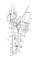
次に図2乃至図9に基づいて、前記部品供給ユニット6について説明する。この部品供給ユニット6はユニット本体であるユニットフレーム21と、部品供給部5に回転自在に装着した収納テープ供給リールに巻回した状態で順次繰り出された収納テープCを電子部品のピックアップ位置PU(部品取出位置)まで間欠送りするテープ送り機構(テープ送り装置)22と、電子部品のピックアップ位置の手前で収納テープCのカバーテープCaを引き剥がすための後述するカバーテープ剥離機構20とから構成される。   Next, the component supply unit 6 will be described with reference to FIGS. The component supply unit 6 includes a unit frame 21 which is a unit main body, and a storage tape C which is sequentially wound in a state of being wound around a storage tape supply reel which is rotatably mounted on the component supply unit 5. A tape feeding mechanism (tape feeding device) 22 that intermittently feeds to the component take-out position), and a cover tape peeling mechanism 20 to be described later for peeling the cover tape Ca of the storage tape C before the pickup position of the electronic component. The

図6に示すように、前記収納テープ供給リールから繰り出された収納テープCは、ピックアップ位置PUの手前のテープ経路に配設したサプレッサ23の下側を潜るようにして、ピックアップ位置PUに送り込まれる。このサプレッサ23にはピックアップ用の開口23Aが開設され。またスリット23Bも形成されており、このスリット23Bを介して収納テープCのカバーテープCaがカバーテープ剥離機構20によりキャリアテープCcから剥離され、収納空間Sを有するカバーテープ回収収納部26内に収納される。即ち、カバーテープ剥離機構によりカバーテープCaが剥離された状態で、キャリアテープCcの部品収納部Cbに搭載した電子部品Dは送り機構22によりピックアップ位置PUまで送られ、開口23Aを介して前記吸着ノズル18によりピッアップされることとなる。   As shown in FIG. 6, the storage tape C fed out from the storage tape supply reel is fed to the pickup position PU so as to lie under the suppressor 23 disposed in the tape path in front of the pickup position PU. . The suppressor 23 is provided with an opening 23A for pickup. A slit 23B is also formed, and the cover tape Ca of the storage tape C is peeled from the carrier tape Cc by the cover tape peeling mechanism 20 through the slit 23B, and stored in the cover tape collecting and storing part 26 having the storage space S. Is done. That is, in a state where the cover tape Ca is peeled off by the cover tape peeling mechanism, the electronic component D mounted on the component storage portion Cb of the carrier tape Cc is sent to the pickup position PU by the feed mechanism 22 and is adsorbed through the opening 23A. It is picked up by the nozzle 18.

次に、前記テープ送り機構22について説明する。テープ送り機構22は、その出力軸に第1歯車を設けた正逆転可能な駆動源であるサーボモータ25(図7参照)と、前記第1歯車との間にタイミングベルトが張架された第2歯車を一端部に備えて支持体にベアリングを介して回転可能に支持された回転軸(図示せず)と、この回転軸の中間部に設けられたウォーム歯車と噛み合うウォームホィール28を備えると共に収納テープに形成した送り孔に噛み合ってこれを送るスプロケット27とから構成される。そして、ユニットフレーム21の中間仕切体をウォームホィール28及びスプロケット27の支軸29が貫通している。   Next, the tape feeding mechanism 22 will be described. The tape feeding mechanism 22 has a first belt having a timing belt stretched between a servomotor 25 (see FIG. 7) that is a drive source capable of forward and reverse rotation having a first gear on its output shaft. A rotary shaft (not shown) having two gears at one end and rotatably supported by a support via a bearing, and a worm wheel 28 meshing with a worm gear provided at an intermediate portion of the rotary shaft, The sprocket 27 is configured to mesh with a feed hole formed in the storage tape and feed it. The worm wheel 28 and the support shaft 29 of the sprocket 27 pass through the intermediate partition body of the unit frame 21.

従って、部品供給ユニット6における収納テープC内の電子部品を供給すべく前記サーボモータ25が駆動して正転すると、タイミングベルトを介して第1及び第2歯車が回転することにより回転軸のみ回転し、ウォーム歯車及びウォームホィール28を介してスプロケット27が送り方向に所定角度間欠回転することにより、収納テープCの前記送り孔を介して収納テープCが間欠送りされる。   Accordingly, when the servo motor 25 is driven to rotate in order to supply the electronic components in the storage tape C in the component supply unit 6, only the rotation shaft is rotated by the rotation of the first and second gears via the timing belt. The storage tape C is intermittently fed through the feed hole of the storage tape C by intermittently rotating the sprocket 27 by a predetermined angle in the feed direction through the worm gear and the worm wheel 28.

また、前記サプレッサ23は支持部となる両垂直片とスプロケット27の歯に送り孔が噛み合った収納テープCが外れないように押さえる水平片とから概ね断面がコ字形状を呈し、前記ユニットフレーム21に係止されると共にこの係止が解除されると前記垂直片が後部のピン30を支点として回動可能に支持される。そして、このサプレッサ23前部がロックされると、このサプレッサ23は下方に付勢されて、前記サプレッサ23は収納テープCやカバーテープ剥離後のキャリアテープCcをテープ案内シュート24に常時押圧してスプロケット27のテープ送り歯からキャリアテープCcの送り孔が抜けて外れないように作用する。   The suppressor 23 has a substantially U-shaped cross section from both vertical pieces serving as support portions and a horizontal piece that holds the storage tape C engaged with the teeth of the sprocket 27 so as not to come off. When the lock is released, the vertical piece is supported so as to be rotatable about the rear pin 30 as a fulcrum. When the front portion of the suppressor 23 is locked, the suppressor 23 is urged downward, and the suppressor 23 constantly presses the carrier tape Cc after the storage tape C and the cover tape are peeled against the tape guide chute 24. It acts so that the feed hole of the carrier tape Cc is not detached from the tape feed teeth of the sprocket 27.

なお、収納テープCのカバーテープの剥離支点となる前記サプレッサ23を上方へ回動させて保持した状態で、部品供給ユニット6の側方から前記ユニットフレーム21に形成された装填用開口31を介して前記収納テープを部品供給ユニット6に装填できるように構成される。   In the state where the suppressor 23 serving as a peeling fulcrum of the cover tape of the storage tape C is rotated and held upward, the side of the component supply unit 6 passes through the loading opening 31 formed in the unit frame 21. The storage tape can be loaded into the component supply unit 6.

次に、前記カバーテープ剥離機構20について、図3乃至図5に基づいて説明する。カバーテープ剥離機構20は、その出力軸にウォーム歯車41を設けた正逆転可能なカバーテープを送るモータ(以下、回収用駆動モータという。)42と、支軸46を介して回転可能で前記歯車41と噛み合う歯車43及び第1平歯車(図示せず)と支軸50を介して回転可能で前記第1平歯車と噛み合う第2平歯車52と歯車47とを備えてユニットフレーム21に固定された支持体44と、支軸56を介して回転可能で前記歯車47と噛み合う歯車51を備え支軸53を介してユニットフレーム21に揺動可能に支持されるもバネ55により前記歯車47に歯車51が噛み合うように付勢される操作体54と、内部にローラー60を介在させた支軸58を介して揺動可能である剥離レバー59にその底面59Aに固定された支持ピン61に巻装してユニットフレーム21に固定された取付片62との間に介挿されたスプリング63により剥離レバー59を反時計回り方向(図2における)へ付勢して前記剥離レバー59の他端に支持されたローラー64及び前記ローラー60に案内されたカバーテープCaにテンションを加えるためのテンション印加体65とから構成される。   Next, the cover tape peeling mechanism 20 will be described with reference to FIGS. The cover tape peeling mechanism 20 has a worm gear 41 on its output shaft and feeds a cover tape that can be rotated forward and backward (hereinafter referred to as a recovery drive motor) 42, and can rotate via a support shaft 46. 41, a gear 43 and a first spur gear (not shown) that engage with the gear 41, and a second spur gear 52 that engages with the first spur gear and a gear 47 that are rotatable via the support shaft 50 and are fixed to the unit frame 21. A support body 44 and a gear 51 that can rotate through a support shaft 56 and mesh with the gear 47 are supported by the unit frame 21 through a support shaft 53 so as to be swingable. The support pin 6 fixed to the bottom surface 59A of the operating body 54 urged so as to engage with the pin 51 and the peeling lever 59 that can swing through the support shaft 58 with the roller 60 interposed therein. The release lever 59 is biased in the counterclockwise direction (in FIG. 2) by a spring 63 interposed between the mounting piece 62 and the mounting piece 62 fixed to the unit frame 21. It comprises a roller 64 supported at the end and a tension applying body 65 for applying tension to the cover tape Ca guided by the roller 60.

尚、66は前記剥離レバー59の側壁下端に設けられた断面L字形状の被検出部である作動片で、前記カバーテープCaのテンションが強くなって前記スプリング63の付勢力に抗して前記剥離レバー59が図2の時計回り方向に揺動したときに、発光素子68と受光素子69との間に前記作動片66が位置して検出装置であるカバーテープのテンション検出用の検出センサー(以下、テンション検出センサという。)67が作動片66を検出することとなる。従って、テンション検出センサー67が作動片66を検出するとカバーテープに所定のテンションが掛かっているものと、また作動片66を検出しないとカバーテープに所定のテンションが掛かっていないものと検出することとなる。   Reference numeral 66 denotes an operating piece which is a detected portion having an L-shaped cross section provided at the lower end of the side wall of the peeling lever 59. The tension of the cover tape Ca is strengthened and the spring 63 is resisted against the urging force of the spring 63. When the peeling lever 59 swings in the clockwise direction in FIG. 2, the operating piece 66 is positioned between the light emitting element 68 and the light receiving element 69, and a detection sensor for detecting the tension of the cover tape as a detection device ( Hereinafter, it is referred to as a tension detection sensor.) 67 detects the operating piece 66. Accordingly, when the tension detecting sensor 67 detects the operating piece 66, it is detected that a predetermined tension is applied to the cover tape, and if the operating piece 66 is not detected, it is detected that the predetermined tension is not applied to the cover tape. Become.

カバーテープCaを回収するときには、前記駆動モータ42が駆動すると、ウォーム歯車41が回転し、さらに歯車43、歯車47及び歯車51が回転し、即ちバネ55により付勢されて歯車47及び歯車51がカバーテープCaを挟んだ状態で回転し、カバーテープCaが緩み(弛み)を生ずることなく、部品供給ユニット6の端部に設けられたカバーテープ回収収納部26内に収納される。   When collecting the cover tape Ca, when the drive motor 42 is driven, the worm gear 41 is rotated, and the gear 43, the gear 47, and the gear 51 are rotated, that is, urged by the spring 55, and the gear 47 and the gear 51 are rotated. The cover tape Ca rotates with the cover tape Ca interposed therebetween, and the cover tape Ca is housed in the cover tape collecting and housing part 26 provided at the end of the component supply unit 6 without causing loosening (slack).

また、歯車47及び歯車51は同様な形状であり、間隔を存して2枚歯を形成し、その歯47A及び51Aを丸みを帯びた形状にする。このような形状とすることにより、歯車47と歯車51との間を通過した剥離後のカバーテープCaに折り目が形成されないようにする。   Further, the gear 47 and the gear 51 have the same shape, and two teeth are formed with a space therebetween, and the teeth 47A and 51A are rounded. By setting it as such a shape, a crease | fold is not formed in the cover tape Ca after peeling which passed between the gear 47 and the gear 51. FIG.

また、前記操作体54の上壁には剥離後のカバーテープCaが前記歯車51に沿ってつられて上方へ行かないようにするスクレーパ48がビス49により固定されている。従って、このスクレーパ48の一側面に突出形成された規制案内部48Aが2枚歯が形成された間の溝51B内に入り込むように固定される。   A scraper 48 is fixed to the upper wall of the operation body 54 with screws 49 so that the peeled cover tape Ca is attached along the gear 51 and does not go upward. Therefore, the regulation guide portion 48A formed to project from one side surface of the scraper 48 is fixed so as to enter the groove 51B while the two teeth are formed.

なお、部品供給ユニット6のフィーダベース19への取付の際に、作業者が把手70を持って被案内部材71がフィーダベース19に設けられた一対の案内部材に案内されながら該部品供給ユニット6を奥行き方向に移動させて、ローラー72が電子部品装着装置本体1に設けられる係止部材に係止することとなる。そして、一対の案内部材に被案内部材71が案内されて、フィーダベース19上を被案内部材71を摺動(スライド)させながら、前記部品供給ユニット6を取付るべく移動させた際に、フィーダベース19の奥行き側の端部には前記被案内部材71が当接することにより当該部品供給ユニット6の前後方向の位置を規制する前後規制部材(図示せず)が設けられている。   When the component supply unit 6 is attached to the feeder base 19, an operator holds the handle 70 and the guided member 71 is guided by a pair of guide members provided on the feeder base 19. Is moved in the depth direction, and the roller 72 is locked to a locking member provided in the electronic component mounting apparatus main body 1. When the guided member 71 is guided by the pair of guide members and the guided member 71 is slid on the feeder base 19 and moved to attach the component supply unit 6, the feeder is moved. A front-rear restricting member (not shown) that restricts the position of the component supply unit 6 in the front-rear direction when the guided member 71 abuts is provided at the depth side end of the base 19.

そして、前記カバーテープ回収収納部26の収納空間Sを形成する外部開口部を閉塞する磁性体である開閉扉73の下端が支軸74を巻くようにして外部開口部に設けた磁石に吸着されるように構成されて、回動可能に支持されている。   Then, the lower end of the open / close door 73, which is a magnetic body that closes the external opening that forms the storage space S of the cover tape collecting and storing part 26, is attracted to the magnet provided in the external opening so as to wind the support shaft 74. It is comprised so that it can rotate and is supported.

また、102は収納テープCの継ぎ目検出装置で、部品供給ユニット6の後端部に取り付けられる取付部材103に設けられる。図7及び図8に示したように、この継ぎ目検出装置102は、発光素子102Aと受光素子102Bとが例えば8ミリメートル離れた間隔を存して設けられた装置本体104、上端部にプリズム105が設けられて断面がコ字形状であり、中間部は収納テープCが通過するようにテープ通路用開口部106が設けた通路形成体107とから構成される。   Reference numeral 102 denotes a joint detection device for the storage tape C, which is provided on the attachment member 103 attached to the rear end portion of the component supply unit 6. As shown in FIGS. 7 and 8, the seam detection device 102 includes a device main body 104 in which a light emitting element 102A and a light receiving element 102B are provided with an interval of, for example, 8 millimeters, and a prism 105 at the upper end. It is provided with a U-shaped cross section, and the intermediate portion is constituted by a passage forming body 107 provided with a tape passage opening 106 so that the storage tape C can pass therethrough.

即ち、収納テープCの送り動作に伴って、継ぎ目が無い収納テープCが継ぎ目検出装置102を通過するときには、各送り孔(4ミリメートル間隔で開設)Cbが発光素子102A及び受光素子102Bに対向した位置にある毎に発光素子102Aからの光が送り孔Cbを介してプリズム105で回帰反射させて受光素子102Bにより受光されるので、継ぎ目検出装置102により継ぎ目無しを検出でき、継ぎ目が有る収納テープCにあっては、送り動作に伴い発光素子102Aからの光が送り孔Cbを覆う連結テープ108Aにより遮光され受光素子102Bにより受光されず、継ぎ目有りが検出されることになる(図9及び図10参照)。   That is, when the storage tape C without a seam passes through the seam detection device 102 with the feeding operation of the storage tape C, each feed hole (opened at intervals of 4 millimeters) Cb faces the light emitting element 102A and the light receiving element 102B. Since the light from the light emitting element 102A is reflected back by the prism 105 through the feed hole Cb and received by the light receiving element 102B every time it is in the position, the seam detection device 102 can detect the absence of a seam, and the storage tape has a seam. In C, the light from the light emitting element 102A is shielded by the connecting tape 108A covering the feed hole Cb and not received by the light receiving element 102B with the feeding operation, and the presence of a joint is detected (FIGS. 9 and 9). 10).

なお、前記連結テープ108Aは、連結テープ108B及び108Cと共に電子部品数が少なくなった古い収納テープCと新しい収納テープCとを連結するためのものであり、連結テープ108Aの部分が継ぎ目である。   The connecting tape 108A is used to connect the old storage tape C and the new storage tape C whose number of electronic components is reduced together with the connection tapes 108B and 108C, and the connecting tape 108A is a joint.

次に図11に基づいて、本電子部品装着装置の制御ブロック図について説明する。110は本電子部品装着装置の電子部品装着に係る動作を統括制御する制御部としてのCPU、111は記憶装置としてのRAM(ランダム・アクセス・メモリ)及び112はROM(リ−ド・オンリー・メモリ)である。   Next, a control block diagram of the electronic component mounting apparatus will be described with reference to FIG. 110 is a CPU as a control unit that performs overall control of operations related to electronic component mounting of the electronic component mounting apparatus, 111 is a RAM (random access memory) as a storage device, and 112 is a ROM (read-only memory). ).

前記RAM111には、装着順序毎(ステップ番号毎)にプリント基板P内でのX方向、Y方向及び角度情報や各部品供給ユニット6の配置番号情報等のプリント基板Pの種類毎に装着データが記憶されており、また前記各部品供給ユニット6の配置番号に対応した各電子部品の種類(部品ID)及び各吸着ノズルの種類の情報(部品配置データ)が格納されている。更に、この部品ID毎に電子部品の特徴を表す項目で構成された部品ライブラリデータも記憶されている。   The RAM 111 has mounting data for each type of printed circuit board P such as X direction, Y direction and angle information in the printed circuit board P, and arrangement number information of each component supply unit 6 for each mounting order (for each step number). Further, the electronic component type (component ID) corresponding to the arrangement number of each component supply unit 6 and the information (component arrangement data) of each suction nozzle type are stored. Furthermore, component library data composed of items representing the characteristics of the electronic component for each component ID is also stored.

そして、CPU110は前記RAM111に記憶されたデータに基づいて、前記ROM112に格納されたプログラムに従い、電子部品装着装置の部品装着動作に係る動作を統括制御する。即ち、CPU110は、駆動回路113を介して前記X軸駆動モータ12X、Y軸駆動モータ12Y、θ軸駆動モータ18A及び上下軸モータ18B等の駆動を制御している。   Based on the data stored in the RAM 111, the CPU 110 controls the operation related to the component mounting operation of the electronic component mounting apparatus according to the program stored in the ROM 112. That is, the CPU 110 controls driving of the X-axis drive motor 12X, the Y-axis drive motor 12Y, the θ-axis drive motor 18A, the vertical axis motor 18B, and the like via the drive circuit 113.

117はインターフェース118を介して前記CPU110に接続される認識処理装置で、前記部品認識カメラ14や基板認識カメラ17により撮像して取込まれた画像の認識処理が該認識処理装置117にて行われ、CPU110に処理結果が送出される。即ち、CPU110は、部品認識カメラ14や基板認識カメラ17に撮像された画像を認識処理(位置ずれ量の算出など)するように指示を認識処理装置117に出力すると共に、認識処理結果を認識処理装置117から受取るものである。   A recognition processing device 117 is connected to the CPU 110 via the interface 118. The recognition processing device 117 performs recognition processing of an image captured by the component recognition camera 14 or the board recognition camera 17. The processing result is sent to the CPU 110. That is, the CPU 110 outputs an instruction to the recognition processing device 117 so as to perform recognition processing (calculation of misalignment amount, etc.) on the image captured by the component recognition camera 14 or the board recognition camera 17 and recognizes the recognition processing result. It is received from the device 117.

即ち、前記認識処理装置117の認識処理により位置ずれ量が把握されると、その結果がCPU110に送られ、CPU110は前記XYステージ12のX軸駆動モータ12X、Y軸駆動モータ12Y及びθ軸駆動モータ18Aを補正移動させて電子部品をプリント基板P上に装着するように制御する。   That is, when the amount of displacement is grasped by the recognition processing of the recognition processing device 117, the result is sent to the CPU 110, and the CPU 110 drives the X-axis drive motor 12X, the Y-axis drive motor 12Y and the θ-axis drive of the XY stage 12. Control is performed so that the motor 18A is corrected and moved to mount the electronic component on the printed circuit board P.

表示装置としてのモニター119にはデータ設定のための入力手段としての種々のタッチパネルスイッチ120が設けられ、作業者がタッチパネルスイッチ120を操作することにより種々の設定を行うことができ、設定データはRAM111に格納される。   The monitor 119 as a display device is provided with various touch panel switches 120 as input means for data setting, and various settings can be performed by an operator operating the touch panel switch 120. The setting data is stored in the RAM 111. Stored in

130はインターフェース118を介してCPU110に接続されるコネクタで、各電子部品装着装置側コネクタ130Aとこれに着脱可能な各部品供給ユニット側コネクタ130Bとから構成され、部品供給ユニット側コネクタ130Bは駆動回路131を介してサーボモータ25及び駆動モータ42に接続されている。コネクタ130、駆動回路131、サーボモータ25及び駆動モータ42は各部品供給ユニット6毎に設けられている。   A connector 130 is connected to the CPU 110 via an interface 118, and includes an electronic component mounting device side connector 130A and a component supply unit side connector 130B that can be attached to and detached from the electronic component mounting device side connector 130B. The servo motor 25 and the drive motor 42 are connected via 131. The connector 130, the drive circuit 131, the servo motor 25, and the drive motor 42 are provided for each component supply unit 6.

また、部品供給ユニット6が図13に示したように2つの収納テープを用いて電子部品を並行に供給できるようにしたデュアルレーンを備え、2箇所の電子部品ピックアップ位置141から電子部品をピックアップするデュアルレーンフィーダである場合には、駆動回路131、サーボモータ25、駆動モータ42、テンション検出センサー67及び継ぎ目検出装置102はそれぞれのレーン毎に設けられるが、図11では便宜上1つのみ図示してある。   Further, as shown in FIG. 13, the component supply unit 6 includes a dual lane that can supply electronic components in parallel using two storage tapes, and picks up electronic components from two electronic component pickup positions 141. In the case of a dual lane feeder, the drive circuit 131, the servo motor 25, the drive motor 42, the tension detection sensor 67, and the joint detection device 102 are provided for each lane, but only one is shown in FIG. 11 for convenience. is there.

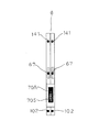
更に、この部品供給ユニット6がデュアルレーンフィーダである場合には、例えば部品供給ユニット6の把手70の上面に設けられた表示部70A(図2及び図13参照)には、左右のレーンに対応して表示手段としての7セグメント表示ユニット(以下、表示ユニットという。)77が設けられている。   Further, when the component supply unit 6 is a dual lane feeder, the display unit 70A (see FIGS. 2 and 13) provided on the upper surface of the handle 70 of the component supply unit 6 corresponds to the left and right lanes. A 7-segment display unit (hereinafter referred to as display unit) 77 is provided as a display means.

また、表示部70Aには、表示ユニット77で表示する対象を切り換えるための切り換えスイッチ70Sが設けられている。また、テンション検出センサ67及び継ぎ目検出装置102の検出状態に応じて表示ユニット77による表示を制御する制御装置である図示しないCPUが設けられている。そして、切り換えスイッチ70Sが操作されていないときには、表示ユニット77は、部品供給ユニット6の運転中に、異常が発生したときに、後述するカバーテープの満杯状態等の異常状態を表示する。   The display unit 70 </ b> A is provided with a changeover switch 70 </ b> S for switching an object to be displayed on the display unit 77. Further, a CPU (not shown), which is a control device that controls display by the display unit 77 in accordance with the detection states of the tension detection sensor 67 and the joint detection device 102, is provided. When the changeover switch 70S is not operated, the display unit 77 displays an abnormal state such as a cover tape full state to be described later when an abnormality occurs during the operation of the component supply unit 6.

以下、図8のフローチャート図に基づいて、部品供給ユニット6の動作について説明する。先ず、CPU110は収納テープCのテープ送り指令が発生されているか(ON)否かを判定し、発生されていると判定すると、テープ送り用のサーボモータ25の駆動を開始するように制御する。   The operation of the component supply unit 6 will be described below based on the flowchart of FIG. First, the CPU 110 determines whether or not a tape feed command for the storage tape C has been generated (ON). If it is determined that it has been generated, the CPU 110 controls to start driving the servo motor 25 for tape feed.

従って、サーボモータ25の駆動による収納テープの送り動作が開始され、以下カバーテープのテンション検出の監視及び回収制御がなされることとなる。即ち、初めに、CPU110はカバーテープのテンション検出用の検出センサ67が通光状態のOFFの状態か否かを判定する。即ち、カバーテープテンション検出用検出センサ67が作動片66が発光素子68と受光素子69との間に位置していない通光状態のOFFの状態か否かを判定する。   Accordingly, the feeding operation of the storage tape by the drive of the servo motor 25 is started, and the detection of the tension of the cover tape and the collection control are performed thereafter. That is, first, the CPU 110 determines whether or not the detection sensor 67 for detecting the tension of the cover tape is in the light-off state. In other words, the detection sensor 67 for detecting the cover tape tension determines whether or not the operating piece 66 is in the light-transmitting state where the operating piece 66 is not positioned between the light emitting element 68 and the light receiving element 69.

この場合、送り動作開始直後のために、カバーテープのCaにテンションがあって緩みが発生していないので検出センサ67が遮光状態を検出し、CPU110はカバーテープの回収用駆動モータ42をOFF(停止)し、回収用駆動モータ42作動時間の監視タイマー121をリセットさせる。   In this case, just after the feeding operation is started, the cover tape Ca has tension and no looseness occurs, so that the detection sensor 67 detects the light shielding state, and the CPU 110 turns off the cover tape collecting drive motor 42 ( And the monitoring timer 121 for the operation time of the recovery drive motor 42 is reset.

次に、テープ送りサーボモータ25が動作中か否かが判定され、動作中であるので、前述したような検出センサ67が通光状態であってOFFの状態か否かの判定動作に戻る。そして、サーボモータ25の駆動による収納テープCの送り動作に伴い、剥離レバー59が反時計方向に揺動してカバーテープCaを剥離してカバーテープに緩みが発生して、検出センサ67が通光状態を検出したと判定すると、カバーテープの回収用駆動モータ42が動作中か否かが判定されて動作中でないので、回収用駆動モータ42が動作し、回収用駆動モータ42の作動時間を計時する監視タイマー121がセットされる。   Next, it is determined whether or not the tape feed servomotor 25 is in operation. Since it is in operation, the operation returns to the determination operation as to whether or not the detection sensor 67 is in the light-transmitting state and is in the OFF state as described above. With the feeding operation of the storage tape C driven by the servo motor 25, the peeling lever 59 swings counterclockwise to peel the cover tape Ca and the cover tape is loosened. If it is determined that the light state is detected, it is determined whether or not the cover tape recovery drive motor 42 is in operation, and is not in operation. Therefore, the recovery drive motor 42 operates and the operation time of the recovery drive motor 42 is increased. A monitoring timer 121 for timing is set.

次に、前記監視タイマー121による回収用駆動モータ42の作動時間の計時時間が満杯予告用判定時間(任意に設定され、変更も可能)を越えたか否かが判定され、まだ満杯予告用判定時間を越えていないと判定されると、次に前記監視タイマー121による回収用駆動モータ42の作動時間の計時時間が満杯予告用判定時間より長い異常停止のためのタイムアウト判定時間(任意に設定され、変更も可能)を越えたか否かが判定される。この場合、越えていなければ、再度テープ送りサーボモータ25が動作中か否かが判定され、動作中でなければ、回収用駆動モータ42が動作中か否かが判定され、動作中であるので、前述したような検出センサ67が通光状態であってOFFの状態か否かの判定動作に戻るが、回収用駆動モータ42の動作によりカバーテープをカバーテープ回収収納部26内に収納させる際に剥離レバー59が時計方向に揺動してカバーテープCaの緩みが無くなりテンションが発生して、検出センサ67が遮光状態を検出することとなる。   Next, it is determined whether or not the time measured by the monitoring timer 121 for the operation time of the recovery drive motor 42 has exceeded a full notice determination time (arbitrarily set and can be changed). If it is determined that it does not exceed, a time-out determination time for an abnormal stop (which is arbitrarily set) is set to be longer than the full notice determination time by the monitoring timer 121. It is determined whether or not the change has been exceeded. In this case, if it does not exceed, it is determined again whether or not the tape feed servo motor 25 is operating. If not, it is determined whether or not the recovery drive motor 42 is operating and is operating. The operation returns to the operation of determining whether or not the detection sensor 67 is in the light-transmitting state and is in the OFF state as described above, but when the cover tape is stored in the cover tape recovery storage portion 26 by the operation of the recovery drive motor 42. Then, the peeling lever 59 is swung clockwise, the cover tape Ca is not loosened, tension is generated, and the detection sensor 67 detects the light shielding state.

従って、CPU110はカバーテープの回収用駆動モータ42をOFF(停止)し、回収用駆動モータ42作動時間の監視タイマー121をリセットさせる。そして、再度テープ送りサーボモータ25が動作中か否かが判定され、動作中でないので、次に回収用駆動モータ42が動作中か否かが判定され、動作中でないので、異常登録ありか否かが判定されるが、異常登録が無いので、次の電子部品を取出すための収納テープCのテープ送り指令が発生されているか否かの判定に戻ることとなる。   Accordingly, the CPU 110 turns off (stops) the cover tape collection drive motor 42 and resets the collection drive motor 42 operating time monitoring timer 121. Then, it is determined again whether or not the tape feed servo motor 25 is in operation. Since it is not in operation, it is next determined whether or not the recovery drive motor 42 is in operation. However, since there is no abnormality registration, the process returns to the determination of whether or not the tape feed command for the storage tape C for taking out the next electronic component has been issued.

従って、キャリアテープCcの部品収納部Cbに搭載した電子部品Dは送り機構22によりピックアップ位置PUまで送られる共にカバーテープ剥離機構20によりスリット23Bを介してカバーテープCaが剥離され、ピックアップ用の開口23Aを介して吸着ノズル18によりピッアップされてプリント基板P上に装着されることとなる。   Accordingly, the electronic component D mounted in the component storage portion Cb of the carrier tape Cc is sent to the pickup position PU by the feeding mechanism 22 and the cover tape Ca is peeled off by the cover tape peeling mechanism 20 through the slit 23B, thereby opening the pickup. It is picked up by the suction nozzle 18 through 23A and mounted on the printed circuit board P.

ところで、以上のような収納テープの送り動作や、カバーテープのテンション検出の監視及び回収制御が繰り返されることとなる。   By the way, the feeding operation of the storage tape as described above, the monitoring of the tension detection of the cover tape, and the recovery control are repeated.

このように、カバーテープのテンション検出の監視及び回収動作が繰り返されているとき、作業者が、部品供給ユニット6の検出センサ67或いは継ぎ目検出装置(継ぎ目センサ)102がどのように動作しているか確認するために、切り換えスイッチ70Sを押すと、部品供給ユニット6に設けられたCPUが動作し、表示ユニット77での表示が、異常発生時にそのエラーの内容を表示するエラー表示モードからセンサの動作状態を表示するセンサ状態表示モードに切り換わる。   As described above, when the cover tape tension detection monitoring and the collection operation are repeated, the operator operates how the detection sensor 67 of the component supply unit 6 or the joint detection device (seam sensor) 102 operates. To confirm, when the changeover switch 70S is pressed, the CPU provided in the component supply unit 6 operates, and the display on the display unit 77 is operated from the error display mode in which the content of the error is displayed when an abnormality occurs. Switches to the sensor status display mode that displays the status.

即ち、左右の表示ユニット77において、右側表示ユニット77の下部セグメント91によって、継ぎ目検出装置102の動作状態が表示される。継ぎ目が無い収納テープCが継ぎ目検出装置102を通過しているときには、各送り孔(4ミリメートル間隔で開設)Cbが発光素子102A及び受光素子102Bに対向した位置にある毎に発光素子102Aからの光が送り孔Cbを介してプリズム105で回帰反射させて受光素子102Bにより受光され、この結果、部品供給ユニット6のCPUは受光されている期間、下部セグメント91に点灯信号を出力し、下部セグメント91は点灯する。また、各送り孔(4ミリメートル間隔で開設)Cbが発光素子102A及び受光素子102Bに対向した位置から外れているときには、発光素子102Aからの光が収納テープに遮断され、受光素子102Bに受光されないため、受光されない期間、部品供給ユニット6のCPUは、下部セグメント91に消灯信号を出力する。下部セグメント91は消灯する。   That is, in the left and right display units 77, the operating state of the joint detection device 102 is displayed by the lower segment 91 of the right display unit 77. When the storage tape C without a seam passes through the seam detecting device 102, each time the feed holes (opened at intervals of 4 millimeters) Cb are positioned opposite the light emitting element 102A and the light receiving element 102B, the light emitting element 102A Light is retroreflected by the prism 105 through the feed hole Cb and received by the light receiving element 102B. As a result, the CPU of the component supply unit 6 outputs a lighting signal to the lower segment 91 while receiving light, and the lower segment 91 91 lights up. When each feed hole (opened at intervals of 4 millimeters) Cb is out of the position facing the light emitting element 102A and the light receiving element 102B, the light from the light emitting element 102A is blocked by the storage tape and is not received by the light receiving element 102B. Therefore, during a period in which no light is received, the CPU of the component supply unit 6 outputs a turn-off signal to the lower segment 91. The lower segment 91 is turned off.

この結果、下部セグメント91は収納テープCの送り動作に伴い短い間隔で点滅することになり、作業者は、下部セグメント91の表示状態を確認することによって、継ぎ目検出装置102の入力状態に対応した動作状態、即ち、継ぎ目検出装置102からの信号出力状態を確認でき、継ぎ目検出装置102が正常に動作していることを容易に確認することができる。   As a result, the lower segment 91 blinks at a short interval along with the feeding operation of the storage tape C, and the operator confirms the display state of the lower segment 91 to correspond to the input state of the joint detection device 102. The operation state, that is, the signal output state from the joint detection device 102 can be confirmed, and it can be easily confirmed that the joint detection device 102 is operating normally.

また、中央セグメント92によって、テンション検出用の検出センサ67の動作状態が表示される。このとき、収納テープCの送り動作開始直後のために、カバーテープCaにテンションがあって緩みが発生していなく、作動片66が発光素子68と受光素子69との間に位置しているとき、検出センサ67が遮光状態を検出し、部品供給ユニット6のCPUはONの状態と判断し、中央セグメント92に点灯信号を出力する。この結果、中央セグメント92は、点灯状態にある。   Further, the operation state of the detection sensor 67 for tension detection is displayed by the center segment 92. At this time, immediately after the feeding operation of the storage tape C is started, the cover tape Ca is not loosened due to tension, and the operating piece 66 is positioned between the light emitting element 68 and the light receiving element 69. The detection sensor 67 detects the light shielding state, the CPU of the component supply unit 6 determines that it is ON, and outputs a lighting signal to the central segment 92. As a result, the central segment 92 is in a lighting state.

また、テープ送りサーボモータ25が動作し、サーボモータ25の駆動による収納テープCの送り動作に伴い、カバーテープCaが剥離されカバーテープに緩みが発生して、剥離レバー59が反時計回りの方向に揺動し、作動片66が発光素子68と受光素子69との間から外れたときには、検出センサ67が通光状態を検出する。このため、部品供給ユニット6のCPUは、OFFの状態と判断し、中央セグメント92に消灯信号を出力する。この結果、中央セグメント92は、点灯状態から消灯状態に切り換わる。以後、カバーテープCaが回収され、カバーテープCaにテンションがあって緩みが発生していないときには、中央セグメント92は、点灯し、また、カバーテープCaに緩みが発生したときには、中央セグメント92が消灯する。   Further, the tape feed servo motor 25 is operated, and the cover tape Ca is peeled off due to the feeding operation of the storage tape C driven by the servo motor 25, the cover tape is loosened, and the peeling lever 59 is rotated counterclockwise. When the operating piece 66 is detached from between the light emitting element 68 and the light receiving element 69, the detection sensor 67 detects the light passing state. For this reason, the CPU of the component supply unit 6 determines that it is in an OFF state, and outputs a turn-off signal to the central segment 92. As a result, the central segment 92 is switched from the lit state to the unlit state. Thereafter, when the cover tape Ca is recovered and the cover tape Ca is tensioned and no looseness occurs, the central segment 92 is turned on. When the cover tape Ca is loosened, the central segment 92 is turned off. To do.

この結果、中央セグメント92は収納テープCの送り動作に伴い、点滅することになり、作業者は、中央セグメント92の表示状態によって、検出センサ67の入力状態に対応した信号出力状態である動作状態を確認でき、検出センサが正常に動作していることを容易に確認することができる。   As a result, the central segment 92 blinks with the feeding operation of the storage tape C, and the operator is in an operation state that is a signal output state corresponding to the input state of the detection sensor 67 according to the display state of the central segment 92. Can be easily confirmed that the detection sensor is operating normally.

また、継ぎ目検出装置102に収納テープ同士の継ぎ目部が位置しているときには、上述したように、継ぎ目が有る収納テープCにあっては、送り動作に伴い発光素子102Aからの光が送り孔Cbを覆う連結テープ108Aにより遮光され受光素子102Bにより受光されず、この結果、受光されない期間、部品供給ユニット6のCPUは、下部セグメント91に消灯信号を出力する。下部セグメント91は消灯状態を継続し、このように、収納テープ同士を連結した後、下部セグメント91での表示状態を確認することによっても、継ぎ目検出装置102が正常に動作していることを容易に確認することができる。   Further, when the seam portion between the storage tapes is located in the seam detecting device 102, as described above, in the storage tape C having a seam, the light from the light emitting element 102A is transmitted along the feed hole Cb along with the feed operation. As a result, the CPU of the component supply unit 6 outputs a turn-off signal to the lower segment 91 during a period in which light is not received by the light receiving element 102B and is not received by the light receiving element 102B. The lower segment 91 continues to be turned off, and after connecting the storage tapes as described above, it is easy to confirm that the joint detection device 102 is operating normally by checking the display state of the lower segment 91. Can be confirmed.

継ぎ目を検出している間と継ぎ目でない部分を検出しているときの点灯パターンが相違していることが分かることによって、さらに確実に継ぎ目検出装置102が正常に動作していることを確認できる。即ち、継ぎ目部分で継ぎ目であることを確認できることで、継ぎ目を確実に検出していることが確認できる。   It can be confirmed that the seam detection device 102 is operating normally more reliably by knowing that the lighting pattern is different between when the seam is being detected and when the part that is not the seam is being detected. That is, it can be confirmed that the joint is reliably detected by confirming that the joint is a seam at the joint.

なお、右側表示ユニット77の下部セグメント91によって、右側レーンの継ぎ目検出装置102の動作状態が表示され、また、中央セグメント92によって、右側レーンのテンション検出用の検出センサ67の状態が表示されるのと同様に、左側表示ユニット77の下部セグメント93によって、左側レーンの継ぎ目検出装置102の動作状態が表示され、また、中央セグメント94によって、左側レーンのテンション検出用の検出センサ67の状態が表示される。   The operation state of the seam detection device 102 in the right lane is displayed by the lower segment 91 of the right display unit 77, and the state of the detection sensor 67 for detecting the tension in the right lane is displayed by the center segment 92. Similarly, the lower segment 93 of the left display unit 77 displays the operation state of the left lane seam detection device 102, and the center segment 94 displays the state of the detection sensor 67 for detecting the left lane tension. The

上述したように、センサ状態表示モードによって、各センサの動作状態が表示されているときに、作業者が切り換えスイッチ70Aを押したとき、又は、部品供給ユニット6に後述するカバーテープの満杯等の異常が発生したときには、左右表示ユニット77の表示は上述したようなセンサの動作状態を表示するセンサ状態表示モードから通常のエラー表示モードに切り換わる。   As described above, when the operation state of each sensor is displayed by the sensor state display mode, when the operator presses the changeover switch 70A, or when the part supply unit 6 fills a cover tape described later. When an abnormality occurs, the display of the left and right display unit 77 is switched from the sensor state display mode for displaying the operation state of the sensor as described above to the normal error display mode.

また、このカバーテープの回収作業に伴い、回収用駆動モータ42の動作によりカバーテープがカバーテープ回収収納部26内に収納されるが、回収収納されるカバーテープの量が増加してくると、徐々にカバーテープ回収収納部26内へカバーテープを収納しにくくなってくる。このため、作動片66が発光素子68と受光素子69との間に位置しない状態から位置する状態の遮光状態への移行時間が徐々に長くなって、カバーテープテンション検出用検出センサ67の所定レベルのテンションを検出できるまでの時間が長くなって、結果として回収用駆動モータ42の作動時間が長くなる。この場合、前記監視タイマー121によって、回収用駆動モータ42の作動時間の計時時間が満杯予告用判定時間を越えたことが計時されることとなる。   As the cover tape is collected, the cover tape is stored in the cover tape collecting and storing unit 26 by the operation of the collecting drive motor 42. When the amount of cover tape collected and stored increases, Gradually, it becomes difficult to store the cover tape in the cover tape collecting and storing unit 26. For this reason, the transition time from the state where the operating piece 66 is not positioned between the light emitting element 68 and the light receiving element 69 to the light shielding state gradually increases, and the predetermined level of the detection sensor 67 for detecting the cover tape tension is set. The time until the tension can be detected becomes longer, and as a result, the operation time of the recovery drive motor 42 becomes longer. In this case, it is timed by the monitoring timer 121 that the time measured for the operation time of the recovery drive motor 42 has exceeded the full notification time.

即ち、前述したように、サーボモータ25の駆動による収納テープCの送り動作に伴い、剥離レバー59が反時計方向に揺動してカバーテープCaを剥離してカバーテープに緩みが発生して、検出センサ67が通光状態を検出したと判定すると、回収用駆動モータ42が動作中か否かが判定されて動作中でないので、回収用駆動モータ42が動作し、回収用駆動モータ42の作動時間を計時する監視タイマー121がセットされ、この監視タイマー121が回収用駆動モータ42の作動時間の計時時間が満杯予告用判定時間を越えたことが計時されることとなる。   That is, as described above, with the feeding operation of the storage tape C driven by the servo motor 25, the peeling lever 59 swings counterclockwise to peel the cover tape Ca, and the cover tape is loosened. If the detection sensor 67 determines that the light transmission state has been detected, it is determined whether or not the recovery drive motor 42 is in operation and is not in operation. Therefore, the recovery drive motor 42 operates and the recovery drive motor 42 operates. A monitoring timer 121 for measuring the time is set, and it is timed that the monitoring timer 121 has exceeded the full notification time for the recovery drive motor 42.

すると、満杯予告報知用フラグをON(オン)して、CPU110は満杯予告情報をRAM111に格納し、満杯予告情報をモニター119に表示させて、この部品供給ユニット6のカバーテープ回収収納部26内に回収したカバーテープの量が満杯予告状態となった旨を報知する。   Then, the full notice notification flag is turned on, and the CPU 110 stores the full notice information in the RAM 111 and displays the full notice information on the monitor 119, and the inside of the cover tape collecting and storing unit 26 of the component supply unit 6. Informs that the amount of cover tape collected is full.

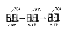
なお、この報知は、視覚的や聴覚的に作業者に報知できる報知手段であれば、その手段の種類は問わない。即ち、この部品供給ユニット6が図13に示したように2つの収納テープを用いて電子部品を並行に供給できるようにしたデュアルレーンを備え、2箇所の電子部品ピックアップ位置141から電子部品をピックアップするデュアルレーンフィーダである場合には、例えば部品供給ユニット6の把手70の上面に設けられた表示部70A(図2及び図13参照)に、一方のレーン(右側)が満杯予告状態の場合には、図14に示すように、一方のレーンに対応した右の7セグメント表示ユニットの下部を0.5秒間毎に点滅させるように制御し、また他方のレーン(左側)が満杯予告状態の場合には、図15に示すように、他方のレーンに対応した左の7セグメント表示ユニットの下部を0.5秒間毎に点滅させるように制御し、更にデュアルレーンがともに満杯予告状態の場合には、図16に示すように、左右の7セグメント表示ユニットの下部を0.5秒間毎に同期させて点滅させるようにCPU110が制御する。   Note that this notification is not limited as long as it is a notification means that can notify the worker visually or audibly. That is, as shown in FIG. 13, the component supply unit 6 includes a dual lane that can supply electronic components in parallel using two storage tapes, and picks up electronic components from two electronic component pickup positions 141. In the case of a dual lane feeder, the display unit 70A (see FIGS. 2 and 13) provided on the upper surface of the handle 70 of the component supply unit 6 is in a state where one lane (right side) is in a full notice state, for example. As shown in FIG. 14, the lower part of the right 7-segment display unit corresponding to one lane is controlled to blink every 0.5 seconds, and the other lane (left side) is in a full notice state. As shown in FIG. 15, the lower part of the left 7-segment display unit corresponding to the other lane is controlled to blink every 0.5 seconds, Lane if both full notice state, as shown in FIG. 16, controls the CPU110 is blinked to synchronize the bottom of the right and left 7-segment display unit every 0.5 seconds.

作業者は、表示部70Aを見ることにより、カバーテープ回収収納部26内に回収したカバーテープの量が満杯予告状態となったことを理解できるので、開閉扉73を開けてカバーテープを回収収納部26より取出して、カバーテープを切断し、回収した収納量を減らす作業を行う。従って、いきなり満杯状態となったから、装置運転を停止するという制御を行うと、電子部品の装着動作の稼働率の悪化を招くが、本実施形態によれば、このような稼働率の悪化を招かないようにすることができる。なお、作業者は、回収した収納量を減らす作業を行った後、部品供給ユニット6のリセットボタン(図示せず)を押すことにより、液晶表示部70Aの表示はリセットされて、点滅は停止する。   The operator can understand that the amount of the cover tape collected in the cover tape collecting and storing unit 26 is in a full notice state by looking at the display unit 70A. Therefore, the operator opens the door 73 and collects and stores the cover tape. Take out from the section 26, cut the cover tape, work to reduce the collected storage amount. Therefore, if the control of stopping the operation of the device is suddenly performed because the battery is suddenly full, the operation rate of the electronic component mounting operation is deteriorated. However, according to the present embodiment, the operation rate is deteriorated. Can be avoided. Note that, after the operator performs an operation to reduce the collected storage amount, the display of the liquid crystal display unit 70A is reset and the blinking stops by pressing a reset button (not shown) of the component supply unit 6. .

しかしながら、このまま満杯予告状態を解消せずに、回収した収納量を減らす作業を行なわなかった場合には、やがて満杯状態となる。この場合には、回収用駆動モータ42の作動時間の計時時間が満杯予告用判定時間より長いタイムアウト判定時間を越えることになるので、監視タイマー121による回収用駆動モータ42の作動時間の計時時間が満杯予告用判定時間より長いタイムアウト判定時間(異常停止)を越えたか否かが判定された際には、回収用駆動モータ42の作動をOFF(停止)し、前記監視タイマー121をリセットし、満杯異常登録を行うためにCPU110はこの部品供給ユニット6はカバーテープが満杯状態であって満杯異常である旨をRAM111に格納させる。   However, if the full notice state is not canceled and the operation for reducing the collected storage amount is not performed, the full state will eventually be reached. In this case, the time measured for the recovery drive motor 42 exceeds the time-out determination time longer than the full notice determination time, so the time measured by the monitoring timer 121 for the recovery drive motor 42 is counted. When it is determined whether or not a timeout determination time (abnormal stop) longer than the full notice determination time has been exceeded, the operation of the recovery drive motor 42 is turned off (stopped), the monitoring timer 121 is reset, and the timer is full. In order to perform the abnormality registration, the CPU 110 stores in the RAM 111 that the component supply unit 6 is in a full state because the cover tape is full.

従って、この満杯異常登録をした後に、テープ送りサーボモータ25が動作中か否かが判定されて動作中ではなく、次に回収用駆動モータ42が動作中か否かが判定され、動作中ではなく、CPU110により異常登録ありか否かが判定された際に、異常登録ありと判定されると、CPU11により異常報知処理がなされる。   Therefore, after this full abnormality registration, it is determined whether or not the tape feed servo motor 25 is in operation and not in operation. Next, it is determined whether or not the recovery drive motor 42 is in operation. Instead, when the CPU 110 determines whether there is an abnormality registration, if it is determined that there is an abnormality registration, the CPU 11 performs an abnormality notification process.

即ち、異常である旨の情報をモニター119に表示させて、この部品供給ユニット6のカバーテープ回収収納部26内に回収したカバーテープの量が満杯で異常状態となった旨を報知する。この報知は、視覚的や聴覚的に作業者に報知できる報知手段であれば、その手段の種類は問わない。満杯時には、満杯予告の報知を停止し、7セグメント表示ユニットを用いて、例えば右レーンのときは「E0.」、左レーンのときは「E.0」と表示して、報知してもよい。   That is, information indicating that there is an abnormality is displayed on the monitor 119 to notify that the amount of the cover tape collected in the cover tape collection and storage section 26 of the component supply unit 6 is full and an abnormal state has occurred. The notification is not limited as long as it is a notification means that can notify the worker visually or audibly. When full, notification of full notice is stopped and a 7-segment display unit may be used to display, for example, “E0.” For the right lane and “E.0” for the left lane. .

いずれにおいても、前述したように、このカバーテープの満杯状態を解消処理した後に、作業者が部品供給ユニット6の前記リセットボタン(図示せず)を押すことにより、液晶表示部70Aの表示はリセットされて、満杯で異常状態となった旨の報知は停止する。   In any case, as described above, the display of the liquid crystal display unit 70A is reset when the operator presses the reset button (not shown) of the component supply unit 6 after the cover tape is full. Then, the notification that it is full and becomes abnormal is stopped.

また、作業者が、部品供給ユニット6のメンテナンス作業、即ち、テンション検出用の検出センサ67或いは、継ぎ目検出装置102の発光素子及び受光素子の清掃などのメンテナンス作業を行った後、作業者が、切り換えスイッチ70Aを押すと、部品供給ユニット6に設けられたCPUが動作し、表示ユニット77での表示が、異常発生時にそのエラーの内容を表示するエラー表示モードからセンサの動作状態を表示するセンサ状態表示モードに切り換わる。   In addition, after the operator performs maintenance work for the component supply unit 6, that is, maintenance work such as cleaning of the detection sensor 67 for tension detection or the light emitting element and the light receiving element of the joint detection device 102, When the changeover switch 70A is pressed, the CPU provided in the component supply unit 6 operates, and the display on the display unit 77 displays the operation status of the sensor from the error display mode in which the error content is displayed when an abnormality occurs. Switch to status display mode.

即ち、上述した供給ユニット6による部品供給運転中と同様に、左右の表示ユニット77において、右側表示ユニット77の下部セグメント91によって、継ぎ目検出装置102の動作状態が表示される。即ち、継ぎ目が無い収納テープCが継ぎ目検出装置102を通過しているときには、各送り孔Cbが発光素子102A及び受光素子102Bに対向した位置にある毎に発光素子102Aからの光が送り孔Cbを介してプリズム105で回帰反射させて受光素子102Bにより受光され、この結果、部品供給ユニット6のCPUは受光されている期間、下部セグメント91に点灯信号を出力し、下部セグメント91は点灯する。また、各送り孔(4ミリメートル間隔で開設)Cbが発光素子102A及び受光素子102Bに対向した位置から外れているときには、発光素子102Aからの光が収納テープに遮断され、受光素子102Bに受光されないため、受光されない期間、部品供給ユニット6のCPUは、下部セグメント91に消灯信号を出力する。下部セグメント91は消灯する。   That is, the operating state of the joint detection device 102 is displayed by the lower segment 91 of the right display unit 77 in the left and right display units 77 as in the parts supply operation by the supply unit 6 described above. That is, when the storage tape C without a seam passes through the seam detection device 102, the light from the light emitting element 102A is sent to the feed hole Cb every time each feed hole Cb is located opposite the light emitting element 102A and the light receiving element 102B. As a result, the CPU of the component supply unit 6 outputs a lighting signal to the lower segment 91, and the lower segment 91 is lit. When each feed hole (opened at intervals of 4 millimeters) Cb is out of the position facing the light emitting element 102A and the light receiving element 102B, the light from the light emitting element 102A is blocked by the storage tape and is not received by the light receiving element 102B. Therefore, during a period in which no light is received, the CPU of the component supply unit 6 outputs a turn-off signal to the lower segment 91. The lower segment 91 is turned off.

この結果、下部セグメント91は収納テープCの送り動作に伴い短い間隔で点滅することになり、作業者は、下部セグメント91の表示状態を確認することによって、継ぎ目検出装置102の動作状態、即ち、継ぎ目検出装置102が正常に動作していることを容易に確認することができる。   As a result, the lower segment 91 blinks at a short interval along with the feeding operation of the storage tape C, and the operator confirms the display state of the lower segment 91, so that the operation state of the joint detection device 102, that is, It can be easily confirmed that the joint detection device 102 is operating normally.

また、中央セグメント92によって、テンション検出用の検出センサ67の動作状態が表示される。このとき、収納テープCの送り動作開始直後のために、カバーテープCaにテンションがあって緩みが発生していなく、作動片66が発光素子68と受光素子69との間に位置しているとき、検出センサ67が遮光状態を検出し、部品供給ユニット6のCPUはONの状態と判断し、中央セグメント92に点灯信号を出力する。この結果、中央セグメント92は、点灯状態にある。   Further, the operation state of the detection sensor 67 for tension detection is displayed by the center segment 92. At this time, immediately after the feeding operation of the storage tape C is started, the cover tape Ca is not loosened due to tension, and the operating piece 66 is positioned between the light emitting element 68 and the light receiving element 69. The detection sensor 67 detects the light shielding state, the CPU of the component supply unit 6 determines that it is ON, and outputs a lighting signal to the central segment 92. As a result, the central segment 92 is in a lighting state.

また、テープ送りサーボモータ25が動作し、サーボモータ25の駆動による収納テープCの送り動作に伴い、カバーテープCaが剥離されカバーテープに緩みが発生して、剥離レバー59が反時計回りの方向に揺動し、作動片66が発光素子68と受光素子69との間から外れたときには、検出センサ67が通光状態を検出する。このため、部品供給ユニット6のCPUは、OFFの状態と判断し、中央セグメント92に消灯信号を出力する。この結果、中央セグメント92は、点灯状態から消灯状態に切り換わる。以後、カバーテープCaが回収され、カバーテープCaにテンションがあって緩みが発生していないときには、中央セグメント92は、点灯し、また、カバーテープCaに緩みが発生したときには、中央セグメント92が消灯する。   Further, the tape feed servo motor 25 is operated, and the cover tape Ca is peeled off due to the feeding operation of the storage tape C driven by the servo motor 25, the cover tape is loosened, and the peeling lever 59 is rotated counterclockwise. When the operating piece 66 is detached from between the light emitting element 68 and the light receiving element 69, the detection sensor 67 detects the light passing state. For this reason, the CPU of the component supply unit 6 determines that it is in an OFF state, and outputs a turn-off signal to the central segment 92. As a result, the central segment 92 is switched from the lit state to the unlit state. Thereafter, when the cover tape Ca is recovered and the cover tape Ca is tensioned and no looseness occurs, the central segment 92 is turned on. When the cover tape Ca is loosened, the central segment 92 is turned off. To do.

この結果、中央セグメント92は収納テープCの送り動作に伴い、点滅することになり、作業者は、中央セグメント92の表示状態によって、検出センサ67の信号出力状態である動作状態を容易に確認でき、検出センサ67が正常に動作していることを確認することができる。   As a result, the central segment 92 blinks with the feeding operation of the storage tape C, and the operator can easily confirm the operation state that is the signal output state of the detection sensor 67 by the display state of the central segment 92. It can be confirmed that the detection sensor 67 is operating normally.

即ち、検出センサ67によるテンション検出の出力状態に応じ、緩みが発生していると中央セグメント92が消灯し、テンションがあり緩みが発生しないと点灯するという異なる表示がされることにより、検出センサ67が正常に動作していることが確認できる。尚、緩み発生のタイミングが分からなくとも所定間隔で点灯と消灯を繰り返すことが確認できるのみでも検出センサ67の正常動作を確認できる。   That is, according to the output state of the tension detection by the detection sensor 67, when the slack is generated, the central segment 92 is turned off, and when the tension is present and the slack is not generated, a different display is displayed. Can be confirmed to be operating normally. Note that the normal operation of the detection sensor 67 can be confirmed only by confirming that lighting and extinguishing are repeated at predetermined intervals without knowing the timing of occurrence of looseness.

なお、右側表示ユニット77の下部セグメント91によって、右側レーンの継ぎ目検出装置102の信号出力状態である動作状態が表示され、また、中央セグメント92によって、右側レーンのテンション検出用の検出センサ67の信号出力状態である動作状態が表示されるのと同様に、左側表示ユニット77の下部セグメント93によって、左側レーンの継ぎ目検出装置102の信号出力状態である動作状態が表示され、また、中央セグメント94によって、左側レーンのテンション検出用の検出センサ67の信号出力状態である動作状態が表示される。   Note that the lower segment 91 of the right display unit 77 displays the operation state that is the signal output state of the seam detection device 102 of the right lane, and the signal of the detection sensor 67 for detecting the right lane tension is displayed by the center segment 92. Similarly to the display of the operation state that is the output state, the lower segment 93 of the left display unit 77 displays the operation state that is the signal output state of the joint detection device 102 in the left lane, and the center segment 94 displays the operation state. The operation state which is the signal output state of the detection sensor 67 for tension detection in the left lane is displayed.

上述した実施の形態では、表示手段として左右に7セグメント表示ユニット77を用いた例について説明したが、このように表示手段に7セグメント表示ユニットを用いることによって、部品供給ユニット6に設けられた複数のセンサ毎の表示するセグメントを指定することによって、各センサの動作状態を一括して同時に表示することができ、且つ同時に表示したときのそれぞれの表示による誤判断を極力回避することができる。   In the above-described embodiment, the example in which the 7-segment display unit 77 is used on the left and right as the display means has been described. However, by using the 7-segment display unit as the display means in this way, By designating the segment to be displayed for each sensor, it is possible to simultaneously display the operation state of each sensor at the same time, and to avoid as much as possible misjudgment due to the display when displaying simultaneously.

また、本発明の表示手段は、上述した実施の形態に限定されるものではなく、表示手段として例えば複数の発光素子を表示部70Aの配列し、これらの発光素子の発光状態の相違によって、エラー表示モードでの表示とセンサ状態表示モードでの表示とを区別するようにしてもよい。   In addition, the display unit of the present invention is not limited to the above-described embodiment, and for example, a plurality of light emitting elements are arranged as the display unit in the display unit 70A, and an error is caused by a difference in the light emitting state of these light emitting elements. You may make it distinguish the display in a display mode, and the display in a sensor state display mode.

また、表示手段として電子部品装着装置本体1に設けられたモニター119を用い、例えば電子部品装着装置本体1に設けられた複数の部品供給ユニット6毎に、また、部品供給ユニットのレーン毎に、モニター119に上述した7セグメンチ表示と同様に、継ぎ目検出装置102の信号出力状態である動作状態を表示し、また、テンション検出用の検出センサ67の信号出力状態である動作状態を表示してもよい。このように、モニター119に表示することによって、電子部品装着装置本体1に設けられた複数の部品供給ユニット6のセンサの動作状態を同時に確認することが可能になる。   Further, a monitor 119 provided in the electronic component mounting apparatus main body 1 is used as a display means. For example, for each of a plurality of component supply units 6 provided in the electronic component mounting apparatus main body 1, and for each lane of the component supply unit, Similarly to the above-described 7-segment display, the monitor 119 displays the operation state that is the signal output state of the joint detection device 102, and also displays the operation state that is the signal output state of the detection sensor 67 for tension detection. Good. In this way, by displaying on the monitor 119, it is possible to simultaneously check the operation states of the sensors of the plurality of component supply units 6 provided in the electronic component mounting apparatus main body 1.

以上のように本発明の実施態様について説明したが、上述の説明に基づいて当業者にとって種々の代替例、修正又は変形が可能であり、本発明はその趣旨を逸脱しない範囲で前述の種々の代替例、修正又は変形を包含するものである。   Although the embodiments of the present invention have been described above, various alternatives, modifications, and variations can be made by those skilled in the art based on the above description, and the present invention is not limited to the various embodiments described above without departing from the spirit of the present invention. It encompasses alternatives, modifications or variations.

電子部品装着装置の平面図である。It is a top view of an electronic component mounting apparatus. 部品供給ユニットの側面図である。It is a side view of a component supply unit. 部品供給ユニットの要部拡大側面図である。It is a principal part enlarged side view of a component supply unit. カバーテープ剥離機構の要部拡大側面図であるIt is a principal part enlarged side view of a cover tape peeling mechanism. 図4のA−A断面図である。It is AA sectional drawing of FIG. 部品供給ユニットの要部拡大縦断面図である。It is a principal part expansion longitudinal cross-sectional view of a components supply unit. 継ぎ目検出装置の側面図である。It is a side view of a seam detection device. 図7における継ぎ目検出装置を矢印方向から見た図である。It is the figure which looked at the joint detection apparatus in FIG. 7 from the arrow direction. 連結テープで連結した収納テープの平面図である。It is a top view of the storage tape connected with the connection tape. 連結テープで連結した収納テープの側面図である。It is a side view of the storage tape connected with the connection tape. 電子部品装着装置の制御ブロック図である。It is a control block diagram of an electronic component mounting apparatus. 収納テープ送り動作・カバーテープの回収動作のフローチャート図である。It is a flowchart figure of storage tape feeding operation | movement and collection | recovery operation | movement of a cover tape. 電子部品供給ユニットの概略説明図である。It is a schematic explanatory drawing of an electronic component supply unit. 7セグメント表示ユニットの概略説明図である。It is a schematic explanatory drawing of a 7 segment display unit. 表示部の点滅動作を示す図である。It is a figure which shows the blink operation | movement of a display part. 表示部の点滅動作を示す図である。It is a figure which shows the blink operation | movement of a display part. 表示部の点滅動作を示す図である。It is a figure which shows the blink operation | movement of a display part.

符号の説明Explanation of symbols

1 電子部品装着装置本体
6 部品供給ユニット
20 カバーテープ剥離機構
22 テープ送り機構
25 サーボモータ
42 回収用駆動モータ
59 剥離レバー
63 スプリング
65 テンション印加体
66 作動片
67 検出センサ
70A 表示部
77 7セグメント表示ユニット(表示手段)
102 継ぎ目検出装置(表示手段)
110 CPU
119 モニター
DESCRIPTION OF SYMBOLS 1 Electronic component mounting apparatus main body 6 Component supply unit 20 Cover tape peeling mechanism 22 Tape feed mechanism 25 Servo motor 42 Recovery drive motor 59 Peeling lever 63 Spring 65 Tension applying body 66 Actuating piece 67 Detection sensor 70A Display part 77 7 segment display unit (Display means)
102 Seam detection device (display means)
110 CPU
119 monitor

Claims (10)

部品取出位置まで収納テープ内の電子部品を供給する部品供給装置であり、この部品供給装置に設けられた検出装置と、この検出装置による検出状態を表示する表示手段とを備えたことを特徴とする電子部品供給装置。   A component supply device that supplies an electronic component in a storage tape to a component pick-up position, comprising a detection device provided in the component supply device, and display means for displaying a detection state by the detection device. Electronic component supply device. 部品取出位置まで収納テープ内の電子部品を供給する部品供給装置であり、この部品供給装置に設けられ検出結果に基づいて信号を出力する検出装置と、この検出装置の信号出力状態を表示する表示手段とを備えたことを特徴とする電子部品供給装置。   A component supply device that supplies electronic components in the storage tape to a component removal position, a detection device that is provided in the component supply device and outputs a signal based on a detection result, and a display that displays a signal output state of the detection device And an electronic component supply device. 部品取出位置まで収納テープ内の電子部品を供給する電子部品供給装置であり、前記収納テープ同士を連結した継ぎ目を検出して検出装置と、この検出装置の検出状態に応じて表示を変化させる表示手段とを備えたことを特徴とする電子部品供給装置。   An electronic component supply device that supplies an electronic component in a storage tape to a component pick-up position, detects a joint connecting the storage tapes, and a display that changes a display according to a detection state of the detection device And an electronic component supply device. 部品取出位置まで収納テープ内の電子部品を供給する電子部品供給装置であり、前記収納テープ同士を連結した連結テープを検出する継ぎ目検出装置と、この検出装置が前記連結テープを検出していないときには、点滅する共に、検出しているときには検出していないときと異なる表示をする表示手段とを備えたことを特徴とする電子部品供給装置。   An electronic component supply device that supplies an electronic component in a storage tape to a component removal position, and a seam detection device that detects a connection tape connecting the storage tapes, and when the detection device does not detect the connection tape An electronic component supply apparatus comprising: a display means that flashes and displays differently when it is detected but not detected. 収納テープのキャリアテープに形成された部品収納部内に収納された電子部品をテープ送り装置により部品取出位置まで間欠送りし、前記部品収納部の上面開口を覆うカバーテープを剥離装置により剥離して前記部品取出位置に送られた電子部品を取り出し可能とすると共に剥離された前記カバーテープのテンションの変化をテンション検出装置によって検出し、回収装置によりカバーテープを回収収納部へ回収するようにした電子部品供給装置であり、前記テンション検出装置の出力状態に応じて、異なる表示をする表示手段とを備えたことを特徴とする電子部品供給装置。   The electronic component housed in the component housing portion formed on the carrier tape of the housing tape is intermittently fed to the component take-out position by the tape feeding device, and the cover tape covering the upper surface opening of the component housing portion is peeled off by the peeling device. An electronic component that enables removal of an electronic component sent to a component extraction position, detects a change in tension of the peeled cover tape by a tension detection device, and recovers the cover tape to a recovery storage unit by a recovery device An electronic component supply device comprising: a supply device, and a display unit that displays differently according to an output state of the tension detection device. 前記表示手段は、7セグメントのLEDから構成され、前記検出装置の検出状態によって点灯、消灯或いは点滅することを特徴とする請求項1乃至5に記載の電子部品供給装置。   The electronic component supply apparatus according to claim 1, wherein the display unit includes a 7-segment LED, and is turned on, turned off, or blinked depending on a detection state of the detection apparatus. フィーダベース上に部品取出位置まで収納テープ内の電子部品を供給する電子部品供給装置を複数並設して、この電子部品供給装置により供給された電子部品を吸着ノズルが取出し部にて取出してプリント基板上に装着する電子部品装着装置において、前記電子部品供給装置に設けられた検出装置の検出状態に応じて点滅する表示手段とを備えたことを特徴とする電子部品装着装置。   A plurality of electronic component supply devices that supply electronic components in the storage tape to the component extraction position are arranged in parallel on the feeder base, and the electronic nozzles supplied by the electronic component supply device are taken out by the pickup unit and printed. An electronic component mounting apparatus mounted on a board, comprising: display means that blinks in accordance with a detection state of a detection device provided in the electronic component supply apparatus. フィーダベース上に部品取出位置まで収納テープ内の電子部品を供給する電子部品供給装置を複数並設して、この電子部品供給装置により供給された電子部品を吸着ノズルが取出し部にて取出してプリント基板上に装着する電子部品装着装置において、前記収納テープ同士を連結した継ぎ目を検出する検出装置と、この検出装置の検出状態を表示する表示手段とを備えたことを特徴とする電子部品装着装置。   A plurality of electronic component supply devices that supply electronic components in the storage tape to the component extraction position are arranged in parallel on the feeder base, and the electronic nozzles supplied by the electronic component supply device are taken out by the pickup unit and printed. An electronic component mounting apparatus mounted on a substrate, comprising: a detection device that detects a joint connecting the storage tapes; and a display unit that displays a detection state of the detection device. . 収納テープのキャリアテープに形成された部品収納部内に収納された電子部品をテープ送り装置により部品取出位置まで間欠送りし、前記部品収納部の上面開口を覆うカバーテープを剥離装置により剥離して前記部品取出位置に送られた電子部品を取り出し可能とすると共に、剥離された前記カバーテープのテンションの変化をテンション検出装置によって検出し、回収装置によりカバーテープを回収収納部へ回収するようにした電子部品供給装置を備え、且つ、前記テンション検出装置の動作状態に応じて異なる表示をする表示手段とを備えたことを特徴とする電子部品装着装置。   The electronic component housed in the component housing portion formed on the carrier tape of the housing tape is intermittently fed to the component take-out position by the tape feeding device, and the cover tape covering the upper surface opening of the component housing portion is peeled off by the peeling device. An electronic device capable of taking out an electronic component sent to a component take-out position, detecting a change in tension of the peeled cover tape with a tension detection device, and collecting the cover tape into a collection storage unit with a collection device. An electronic component mounting apparatus comprising: a component supply device; and display means for displaying different displays depending on an operating state of the tension detection device. 前記表示手段は、7セグメントのLEDから構成され、検出状態によって点灯、消灯或いは点滅することを特徴とする請求項7乃至9に記載の電子部品装着装置。   The electronic component mounting apparatus according to any one of claims 7 to 9, wherein the display means is composed of a 7-segment LED, and is turned on, turned off, or blinked depending on a detection state.
JP2008255729A 2008-09-30 2008-09-30 Electronic component feeder Active JP5155084B2 (en)

Priority Applications (1)

Application Number Priority Date Filing Date Title
JP2008255729A JP5155084B2 (en) 2008-09-30 2008-09-30 Electronic component feeder

Applications Claiming Priority (1)

Application Number Priority Date Filing Date Title
JP2008255729A JP5155084B2 (en) 2008-09-30 2008-09-30 Electronic component feeder

Related Child Applications (1)

Application Number Title Priority Date Filing Date
JP2012267629A Division JP2013048305A (en) 2012-12-06 2012-12-06 Electronic component supply device and electronic component fitting device

Publications (2)

Publication Number Publication Date
JP2010087305A true JP2010087305A (en) 2010-04-15
JP5155084B2 JP5155084B2 (en) 2013-02-27

Family

ID=42250957

Family Applications (1)

Application Number Title Priority Date Filing Date
JP2008255729A Active JP5155084B2 (en) 2008-09-30 2008-09-30 Electronic component feeder

Country Status (1)

Country Link
JP (1) JP5155084B2 (en)

Cited By (13)

* Cited by examiner, † Cited by third party
Publication number Priority date Publication date Assignee Title
KR20120134065A (en) 2011-05-31 2012-12-11 가부시끼가이샤 히다찌 하이테크 인스트루먼츠 Electronic component mounting method and mounting apparatus
JP2013021207A (en) * 2011-07-13 2013-01-31 Panasonic Corp Part feeder and feeder adjustment method
JP2013089931A (en) * 2011-10-24 2013-05-13 Fuji Mach Mfg Co Ltd Tape feeder
JP2013089932A (en) * 2011-10-24 2013-05-13 Fuji Mach Mfg Co Ltd Tape feeder
JP2013206963A (en) * 2012-03-27 2013-10-07 Sony Corp Carrier tape setting method, tape cassette, mounting device, and circuit board manufacturing method
WO2013153731A1 (en) * 2012-04-13 2013-10-17 パナソニック株式会社 Tape feeder, and method for displaying setting information in tape feeder
WO2013153730A1 (en) * 2012-04-13 2013-10-17 パナソニック株式会社 Electronic component mounting device, and method for modifying setting information in electronic component mounting device
JP2014022636A (en) * 2012-07-20 2014-02-03 Hitachi High-Tech Instruments Co Ltd Feeder
WO2017037846A1 (en) * 2015-08-31 2017-03-09 富士機械製造株式会社 Component mounting device, feeder device, and method for determining defect in splicing work
CN106686967A (en) * 2015-11-11 2017-05-17 松下知识产权经营株式会社 Component supplying device and component supplying method
JP2017092343A (en) * 2015-11-13 2017-05-25 富士機械製造株式会社 Component supply feeder
US9776129B2 (en) 2012-03-19 2017-10-03 Atlas Copco Airpower, Naamloze Vennootschap Device and method for separating gases
JP2018041817A (en) * 2016-09-07 2018-03-15 富士機械製造株式会社 Bulk feeder cassette supply device

Citations (4)

* Cited by examiner, † Cited by third party
Publication number Priority date Publication date Assignee Title
JP2000114778A (en) * 1998-09-30 2000-04-21 Matsushita Electric Ind Co Ltd Tape feeder and feeding method
JP2004015040A (en) * 2002-06-07 2004-01-15 Fuji Mach Mfg Co Ltd Taped electronic component feeding device having maintenance time reporting function and electronic component mounting device using the same device, maintenance time reporting method for electronic component feeding device
JP2004047858A (en) * 2002-07-15 2004-02-12 Yamaha Motor Co Ltd Component packaging device
JP2005116599A (en) * 2003-10-03 2005-04-28 Matsushita Electric Ind Co Ltd Electronic component packaging apparatus and tape feeder

Patent Citations (4)

* Cited by examiner, † Cited by third party
Publication number Priority date Publication date Assignee Title
JP2000114778A (en) * 1998-09-30 2000-04-21 Matsushita Electric Ind Co Ltd Tape feeder and feeding method
JP2004015040A (en) * 2002-06-07 2004-01-15 Fuji Mach Mfg Co Ltd Taped electronic component feeding device having maintenance time reporting function and electronic component mounting device using the same device, maintenance time reporting method for electronic component feeding device
JP2004047858A (en) * 2002-07-15 2004-02-12 Yamaha Motor Co Ltd Component packaging device
JP2005116599A (en) * 2003-10-03 2005-04-28 Matsushita Electric Ind Co Ltd Electronic component packaging apparatus and tape feeder

Cited By (20)

* Cited by examiner, † Cited by third party
Publication number Priority date Publication date Assignee Title
KR20120134065A (en) 2011-05-31 2012-12-11 가부시끼가이샤 히다찌 하이테크 인스트루먼츠 Electronic component mounting method and mounting apparatus
JP2013021207A (en) * 2011-07-13 2013-01-31 Panasonic Corp Part feeder and feeder adjustment method
JP2013089931A (en) * 2011-10-24 2013-05-13 Fuji Mach Mfg Co Ltd Tape feeder
JP2013089932A (en) * 2011-10-24 2013-05-13 Fuji Mach Mfg Co Ltd Tape feeder
US9776129B2 (en) 2012-03-19 2017-10-03 Atlas Copco Airpower, Naamloze Vennootschap Device and method for separating gases
JP2013206963A (en) * 2012-03-27 2013-10-07 Sony Corp Carrier tape setting method, tape cassette, mounting device, and circuit board manufacturing method
WO2013153731A1 (en) * 2012-04-13 2013-10-17 パナソニック株式会社 Tape feeder, and method for displaying setting information in tape feeder
WO2013153730A1 (en) * 2012-04-13 2013-10-17 パナソニック株式会社 Electronic component mounting device, and method for modifying setting information in electronic component mounting device
JP2013222738A (en) * 2012-04-13 2013-10-28 Panasonic Corp Tape feeder and display method of setting information in tape feeder
CN104186030A (en) * 2012-04-13 2014-12-03 松下电器产业株式会社 Tape feeder, and method for displaying setting information in tape feeder
US9910428B2 (en) 2012-04-13 2018-03-06 Panasonic Intellectual Property Management Co., Ltd. Electronic component mounting device, electronic component mounting system, and method for modifying setting information in electronic component mounting device and electronic component mounting system
JP2014022636A (en) * 2012-07-20 2014-02-03 Hitachi High-Tech Instruments Co Ltd Feeder
WO2017037846A1 (en) * 2015-08-31 2017-03-09 富士機械製造株式会社 Component mounting device, feeder device, and method for determining defect in splicing work
CN107926146A (en) * 2015-08-31 2018-04-17 富士机械制造株式会社 Component mounter, loader device and the bad decision method for splicing operation
CN107926146B (en) * 2015-08-31 2019-11-05 株式会社富士 The bad determination method of component mounter, loader device and stitching operation
US10881041B2 (en) 2015-08-31 2020-12-29 Fuji Corporation Component mounting machine, feeder device, and splicing work defect determination method
CN106686967A (en) * 2015-11-11 2017-05-17 松下知识产权经营株式会社 Component supplying device and component supplying method
CN106686967B (en) * 2015-11-11 2020-02-28 松下知识产权经营株式会社 Component supply device and component supply method
JP2017092343A (en) * 2015-11-13 2017-05-25 富士機械製造株式会社 Component supply feeder
JP2018041817A (en) * 2016-09-07 2018-03-15 富士機械製造株式会社 Bulk feeder cassette supply device

Also Published As

Publication number Publication date
JP5155084B2 (en) 2013-02-27

Similar Documents

Publication Publication Date Title
JP5155084B2 (en) Electronic component feeder
JP4696182B2 (en) Electronic component mounting device
EP1793660B1 (en) Electronic component mounting apparatus
JP4744241B2 (en) Electronic component mounting device
JP2012074749A (en) Electronic component mounting device
JP4917586B2 (en) Electronic component mounting device
JP4917378B2 (en) Electronic component mounting device
JP4713330B2 (en) Electronic component mounting device
JP2013048305A (en) Electronic component supply device and electronic component fitting device
JP4303174B2 (en) Electronic component mounting device
JP6082280B2 (en) Electronic component supply unit and electronic component mounting apparatus
JP4450809B2 (en) Electronic component mounting device
JP4378428B2 (en) Electronic component mounting device
JP4887067B2 (en) Electronic component mounting device
JP4722744B2 (en) Electronic component mounting device
JP4942712B2 (en) Electronic component mounting device
JP4364293B2 (en) Electronic component mounting device
JP4922460B2 (en) Electronic component mounting device
JP4460071B2 (en) Electronic component mounting device

Legal Events

Date Code Title Description
A621 Written request for application examination

Free format text: JAPANESE INTERMEDIATE CODE: A621

Effective date: 20101029

A977 Report on retrieval

Free format text: JAPANESE INTERMEDIATE CODE: A971007

Effective date: 20120220

A131 Notification of reasons for refusal

Free format text: JAPANESE INTERMEDIATE CODE: A131

Effective date: 20120314

A521 Request for written amendment filed

Free format text: JAPANESE INTERMEDIATE CODE: A523

Effective date: 20120514

TRDD Decision of grant or rejection written
A01 Written decision to grant a patent or to grant a registration (utility model)

Free format text: JAPANESE INTERMEDIATE CODE: A01

Effective date: 20121106

A61 First payment of annual fees (during grant procedure)

Free format text: JAPANESE INTERMEDIATE CODE: A61

Effective date: 20121206

FPAY Renewal fee payment (event date is renewal date of database)

Free format text: PAYMENT UNTIL: 20151214

Year of fee payment: 3

R150 Certificate of patent or registration of utility model

Ref document number: 5155084

Country of ref document: JP

Free format text: JAPANESE INTERMEDIATE CODE: R150

Free format text: JAPANESE INTERMEDIATE CODE: R150

S111 Request for change of ownership or part of ownership

Free format text: JAPANESE INTERMEDIATE CODE: R313113

R350 Written notification of registration of transfer

Free format text: JAPANESE INTERMEDIATE CODE: R350

R250 Receipt of annual fees

Free format text: JAPANESE INTERMEDIATE CODE: R250

R250 Receipt of annual fees

Free format text: JAPANESE INTERMEDIATE CODE: R250

R250 Receipt of annual fees

Free format text: JAPANESE INTERMEDIATE CODE: R250

R250 Receipt of annual fees

Free format text: JAPANESE INTERMEDIATE CODE: R250

R250 Receipt of annual fees

Free format text: JAPANESE INTERMEDIATE CODE: R250

R250 Receipt of annual fees

Free format text: JAPANESE INTERMEDIATE CODE: R250

R250 Receipt of annual fees

Free format text: JAPANESE INTERMEDIATE CODE: R250

R250 Receipt of annual fees

Free format text: JAPANESE INTERMEDIATE CODE: R250

R250 Receipt of annual fees

Free format text: JAPANESE INTERMEDIATE CODE: R250