JP2010086591A - Method for manufacturing magnetic disk - Google Patents
Method for manufacturing magnetic disk Download PDFInfo
- Publication number
- JP2010086591A JP2010086591A JP2008253081A JP2008253081A JP2010086591A JP 2010086591 A JP2010086591 A JP 2010086591A JP 2008253081 A JP2008253081 A JP 2008253081A JP 2008253081 A JP2008253081 A JP 2008253081A JP 2010086591 A JP2010086591 A JP 2010086591A
- Authority
- JP
- Japan
- Prior art keywords
- magnetic disk
- magnetic
- head
- magnetic head
- disk
- Prior art date
- Legal status (The legal status is an assumption and is not a legal conclusion. Google has not performed a legal analysis and makes no representation as to the accuracy of the status listed.)
- Granted
Links
Images


Abstract
Description
本発明は、コンピュータなどに搭載されるハードディスクドライブ装置(HDD)の情報記録媒体として用いられる磁気ディスクの製造方法に関する。 The present invention relates to a method of manufacturing a magnetic disk used as an information recording medium of a hard disk drive (HDD) mounted on a computer or the like.
近年の情報処理の大容量化に伴い、各種の情報記録技術が開発されている。特に磁気記録技術を用いたHDDの面記録密度は年率100%程度の割合で増加し続けている。最近ではHDD等に用いられる2.5インチ径の磁気ディスクにして、1枚あたり250GBを超える情報記録容量が求められるようになってきている。このような情報記録密度の増加に伴い、円周方向の線記録密度(BPI:Bit Per Inch)、半径方向のトラック記録密度(TPI:Track Per Inch)のいずれも増加の一途を辿っている。さらに、磁気ディスクの磁性層と、磁気ヘッドの記録再生素子との間隙(磁気的スペーシング)を狭くしてシグナルノイズ比(Signal-Noise Ratio:SNR)を向上させる技術も検討されている。 Various information recording techniques have been developed with the recent increase in information processing capacity. In particular, the surface recording density of HDDs using magnetic recording technology continues to increase at an annual rate of about 100%. Recently, an information recording capacity exceeding 250 GB has been demanded for a 2.5-inch diameter magnetic disk used for an HDD or the like. As the information recording density increases, both the circumferential linear recording density (BPI: Bit Per Inch) and the radial track recording density (TPI: Track Per Inch) are steadily increasing. Further, a technique for improving a signal-to-noise ratio (SNR) by narrowing a gap (magnetic spacing) between a magnetic layer of a magnetic disk and a recording / reproducing element of a magnetic head has been studied.
HDDの起動停止方式において、磁気ディスクの非使用状態(停止状態)において磁気ヘッドがディスク表面に載置されるCSS方式(コンタクトスタートストップ方式)から停止状態のときに磁気ヘッドがディスク外周側に退避されるLUL方式(ロード・アンロード方式)へほぼ移行している。これにより磁気ディスク上にコンタクト時の吸着防止の凹凸を設ける必要がなくなったため、ディスク表面の更なる平滑化が可能となり、磁気ヘッドの浮上量の狭隘化が図れる。 In the HDD start / stop system, the magnetic head is retracted to the outer circumference of the disk when the magnetic disk is not used (stopped) from the CSS system (contact start / stop system) where the magnetic head is placed on the disk surface. The LUL method (load / unload method) is almost shifted. As a result, it becomes unnecessary to provide the magnetic disk with unevenness for preventing adsorption at the time of contact, so that the disk surface can be further smoothed and the flying height of the magnetic head can be narrowed.
磁気ヘッドの低浮上量化に伴い、外部衝撃や飛行の乱れによって磁気ヘッドがディスク表面に接触する可能性が高まっている。このため磁気ディスクには、磁気ヘッドが衝突した際に、磁気記録層の表面が傷つかないように保護する媒体保護層が設けられ、さらに保護層の上には磁気ヘッドの接触摺動のダメージを緩和するために潤滑剤が塗布されている。潤滑剤の使用例として、例えば特許文献1には、HOCH2−CF2O−(C2F4O)p−(CF2O)q−CH2OHの構造をもつパーフロロアルキルポリエーテルの潤滑剤を塗布した磁気ディスクが開示されている。
As the flying height of the magnetic head is reduced, the possibility that the magnetic head comes into contact with the disk surface due to external impact or flight disturbance is increasing. For this reason, the magnetic disk is provided with a medium protective layer that protects the surface of the magnetic recording layer from being damaged when the magnetic head collides. A lubricant is applied to alleviate. As an example of the use of the lubricant, for example, Patent Document 1, the perfluoroalkyl polyether having the structure HOCH 2 -CF 2 O- (C 2 F 4 O) p- (CF 2 O) q-
潤滑剤を塗布することにより磁気ヘッドの接触時のダメージを低減することが可能であるが、浮上量低下により潤滑層とディスク表面との間で間欠的な接触状態に置かれると、ディスク表面からヘッドスライダ表面への潤滑剤の移着が起こりやすくなる。この移着量が多くなると、ヘッドスライダとディスクと間に潤滑層の架橋が形成されてメニスカス力と呼ばれる吸着力が発生し、ヘッドスライダの安定浮上を妨害する。 It is possible to reduce damage when the magnetic head is in contact by applying a lubricant, but if it is placed in an intermittent contact state between the lubricating layer and the disk surface due to a decrease in the flying height, it will be removed from the disk surface. Lubricant transfer to the head slider surface is likely to occur. When this amount of transfer increases, a bridging layer of the lubricating layer is formed between the head slider and the disk, and an attracting force called meniscus force is generated, which hinders stable flying of the head slider.
SNR向上には、磁気ヘッドの低浮上量化は不可欠であるため、移着の起こりにくい潤滑剤の開発及びその評価方法の確立が必要となる。評価方法の一例として、例えば特許文献2には、磁気ディスクから所定量浮上し、潤滑剤との衝突を圧電素子やAE(Acoustic Emission)センサで検出する浮上ヘッドで、磁気ディスクの回転数を下げていき浮上ヘッドが磁気ディスクの液体潤滑剤と摺動を開始する速度(TDV:Touch Down velocity)と、磁気ディスクの回転数を上げていき浮上ヘッドが磁気ディスクから再浮上して摺動や衝突が終了する速度(TOV:Take Off velocity)との差から、浮上ヘッドの磁気ディスク面からの離脱特性を求める技術が開示されている。また、磁気ヘッドの浮上量を圧力依存で操作するTDP/TOP(Touch Down Pressure/Take off pressure)試験により同様の評価を行うことも可能である(例えば特許文献3参照)。
In order to improve the SNR, it is indispensable to reduce the flying height of the magnetic head. Therefore, it is necessary to develop a lubricant that hardly causes transfer and to establish an evaluation method thereof. As an example of an evaluation method, for example,
従来のTDP/TOP測定等により潤滑剤のメニスカス力が大きく離脱特性が悪いと判断された磁気ディスクは、ロード・アンロード耐久試験でも同様に合格率が低く、相関を取ることが可能であった。これにより安定した品質を磁気ディスクに保証することができた。なお、ロード・アンロード耐久試験は、磁気ディスクをハードディスクドライブ装置に搭載し、例えば60万回以上というような多数回に亘って連続してロード・アンロード動作を繰り返すものである。ドライブの動作形態に最も近い評価試験であるが、磁気ディスクと浮上ヘッドを用いる実装試験であり、結果を得るために多大な時間と費用を要する試験である。
近年、HDDはカーナビ、携帯音楽プレーヤー等に用途が展開されている。従来のPC使用時と比較して振動・圧力など環境が大きく変化するため、磁気ヘッドが衝突する機会はさらに増加する。従来よりもさらに高い信頼性、耐久度が磁気ディスクに要求されることとなり、ロード・アンロード耐久試験でも60℃、湿度80%といった過酷な環境下での試験が導入されて評価が行われている。 In recent years, HDDs have been used for car navigation systems, portable music players, and the like. Since the environment such as vibration and pressure changes greatly compared to when using a conventional PC, the chance of the magnetic head colliding further increases. Higher reliability and durability than ever before will be required for magnetic disks, and tests in harsh environments such as 60 ° C and humidity 80% have been introduced and evaluated in load / unload durability tests. Yes.
これまでTDP/TOP試験で良好と判断された磁気ディスクでも60℃、湿度80%ロード・アンロード(hard L/UL)耐久試験では不合格となる事例が増加してきた。さらに磁気ヘッドの浮上量は10nm以下まで低減されたことで、離脱特性試験とロード・アンロード耐久試験との相関を取ることが困難となった。 There have been an increasing number of cases where magnetic disks judged to be good in the TDP / TOP test have failed in the 60 ° C. and 80% humidity load / unload (hard L / UL) endurance test. Furthermore, since the flying height of the magnetic head is reduced to 10 nm or less, it becomes difficult to correlate the separation characteristic test with the load / unload durability test.
本発明はかかる点に鑑みてなされたものであり、磁気ヘッドの浮上量は10nm以下であるHDDのロード・アンロード耐久試験にも合格することができる信頼性の高い磁気ディスクを得ることができる磁気ディスクの製造方法を提供することを目的とする。 The present invention has been made in view of the above points, and it is possible to obtain a highly reliable magnetic disk that can pass a load / unload durability test of an HDD whose flying height of a magnetic head is 10 nm or less. An object of the present invention is to provide a method for manufacturing a magnetic disk.
本発明の磁気ディスクの製造方法は、最上層に潤滑層を有する磁気ディスクの前記潤滑層を評価する評価工程を含む製造方法であって、前記評価工程は、前記磁気ディスクを回転させて前記磁気ディスクの上方に磁気ヘッドを浮上させる磁気ヘッド浮上工程と、前記磁気ディスクを回転させた状態で、測定環境の気圧を徐々に減少させて前記磁気ヘッドを前記磁気ディスクの表面に接触させた後、前記測定環境の気圧を徐々に増加させて前記磁気ヘッドが前記磁気ディスクの表面から浮上したときの圧力を測定するTOP測定工程と、前記TOP測定後の前記磁気ヘッドのスライダ表面への潤滑剤の付着量に基づき、前記磁気ディスクの浮上特性の合否を判定する第1ヘッド判定工程と、前記磁気ディスクを回転させた状態でTOP測定圧力以下の気圧において前記測定環境の気圧を急速に増加させて前記磁気ヘッドを前記磁気ディスクの表面から引き離す急速離脱工程と、前記磁気ヘッドのスライダ表面への潤滑剤の付着量に基づき、前記磁気ディスクの浮上特性の合否を判定する第2ヘッド判定工程と、を含むことを特徴とする。 The method of manufacturing a magnetic disk according to the present invention is a manufacturing method including an evaluation step of evaluating the lubricating layer of a magnetic disk having a lubricating layer as an uppermost layer, wherein the evaluation step rotates the magnetic disk and the magnetic layer is rotated. A magnetic head floating step of floating the magnetic head above the disk, and after rotating the magnetic disk, gradually reducing the atmospheric pressure of the measurement environment to bring the magnetic head into contact with the surface of the magnetic disk; A TOP measurement step of measuring the pressure when the magnetic head floats from the surface of the magnetic disk by gradually increasing the atmospheric pressure of the measurement environment, and the lubricant on the slider surface of the magnetic head after the TOP measurement A first head determination step for determining pass / fail of the flying characteristics of the magnetic disk based on the adhesion amount; and a TOP measurement pressure in a state where the magnetic disk is rotated. The magnetic disk is based on a rapid release step of rapidly increasing the atmospheric pressure of the measurement environment at a lower atmospheric pressure to separate the magnetic head from the surface of the magnetic disk, and the amount of lubricant adhering to the slider surface of the magnetic head. And a second head determining step for determining whether or not the flying characteristics are acceptable.
この方法によれば、磁気ディスクである磁気ディスクの固有の値であるTOPを測定し、測定したTOPを含む所定の圧力間で急速に気圧を増加させて判定を行うので、磁気ヘッドがディスク表面から浮上する際に磁気ヘッドとディスク表面との間に形成されるメニスカス(液体架橋)から磁気ヘッドのスライダへの潤滑剤の移着量を増やすことができる。急速浮上を行った磁気ヘッドのスライダに潤滑剤の付着が確認される磁気ディスクは十分な信頼性を保有していないことが判明したので、ディスク表面から急速浮上を行った磁気ヘッドのスライダにおける潤滑剤の付着を判定することにより、より厳しいロード・アンロード耐久試験にも合格することができる信頼性の高い磁気ディスクを得ることが可能となる。 According to this method, TOP, which is a unique value of a magnetic disk that is a magnetic disk, is measured, and determination is performed by rapidly increasing the atmospheric pressure between predetermined pressures including the measured TOP. The amount of lubricant transferred from the meniscus (liquid bridge) formed between the magnetic head and the disk surface when flying from the magnetic head to the slider of the magnetic head can be increased. Since it was found that the magnetic disk in which the lubricant adhered to the slider of the magnetic head that rapidly flew was not sufficiently reliable, lubrication in the slider of the magnetic head that rapidly flew from the disk surface By determining the adhesion of the agent, it is possible to obtain a highly reliable magnetic disk that can pass a more severe load / unload durability test.
本発明の磁気ディスクの製造方法においては、前記TOP測定工程における気圧の増加速度をA(Torr/sec2)とし、前記急速離脱工程における気圧の増加速度をB(Torr/sec2)とした場合、絶対値がB≧10Aであることが好ましい。 In the method for manufacturing a magnetic disk according to the present invention, the rate of increase in atmospheric pressure in the TOP measurement step is A (Torr / sec 2 ), and the rate of increase in atmospheric pressure in the rapid release step is B (Torr / sec 2 ). The absolute value is preferably B ≧ 10A.
本発明の磁気ディスクの製造方法においては、前記磁気ディスクは、ロード・アンロード方式のハードディスクドライブ装置に用いられる磁気ディスクであることが好ましい。 In the magnetic disk manufacturing method of the present invention, the magnetic disk is preferably a magnetic disk used in a load / unload type hard disk drive device.
本発明の磁気ディスクの製造方法においては、前記磁気ディスクは、2.5インチ以下の直径を有することが好ましい。 In the magnetic disk manufacturing method of the present invention, it is preferable that the magnetic disk has a diameter of 2.5 inches or less.
以下、本発明の実施の形態について添付図面を参照して詳細に説明する。本実施の形態に示す寸法、材料、その他具体的な数値などは、本発明の理解を容易とするための例示にすぎず、特に断る場合を除き、本発明を限定するものではない。 Hereinafter, embodiments of the present invention will be described in detail with reference to the accompanying drawings. The dimensions, materials, and other specific numerical values shown in this embodiment are merely examples for facilitating the understanding of the present invention, and do not limit the present invention unless otherwise specified.
本発明者は、TDP/TOP測定後の磁気ヘッドのスライダへの潤滑剤付着(転写)の有無により浮上特性の合否判定(第1判定)を行うと共に、磁気ディスクを回転させた状態でTOP測定圧力以下の気圧において測定環境の気圧を急速に増加させてスライダへの潤滑剤付着(転写)の有無により浮上特性の合否判定(第2判定)を行う。すなわち、TOPを測定する際に、圧力の増加速度に差を付けてそれぞれ判定を行う。この場合において、圧力の増加速度が相対的に大きい状態でのTOP測定は、厳しい条件下での評価となる。このように2つの条件下で判定を行うことにより、より厳しい環境下での評価を行うことができ、信頼性の高い磁気ディスクを判定することが可能となる。 The inventor makes a pass / fail determination (first determination) of the flying characteristics based on the presence or absence of lubricant adhesion (transfer) to the slider of the magnetic head after the TDP / TOP measurement, and performs the TOP measurement while rotating the magnetic disk. The atmospheric pressure of the measurement environment is rapidly increased at an atmospheric pressure equal to or lower than the pressure, and the pass / fail determination (second determination) of the flying characteristics is performed based on the presence or absence of lubricant adhesion (transfer) to the slider. In other words, when measuring TOP, each difference is determined in the rate of increase in pressure. In this case, TOP measurement in a state where the pressure increase rate is relatively large is evaluated under severe conditions. By performing the determination under the two conditions as described above, it is possible to perform an evaluation under a harsher environment and to determine a highly reliable magnetic disk.
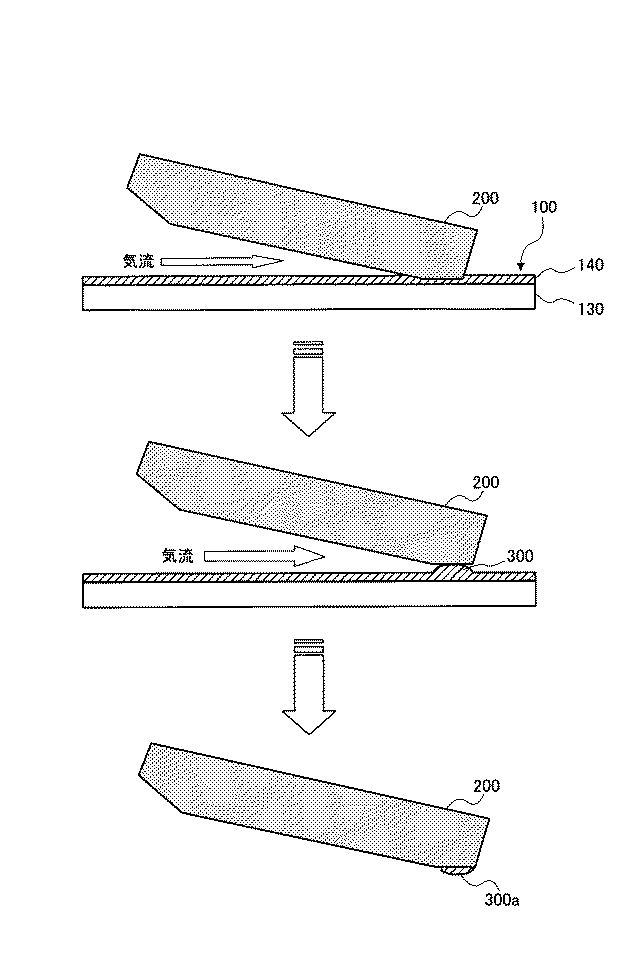
図5は、TOP測定時における磁気ヘッドのスライダへの潤滑剤付着過程を示す図である。同図において、磁気ヘッドのスライダ200が磁気ディスク100の表面から浮上する場合、媒体保護層130上に形成された潤滑層140を構成する潤滑剤は液体としての性質を持つため、磁気ヘッドのスライダ200とディスク表面との間にメニスカス300が形成される。通常のTOPよりも急速で磁気ヘッドを引き離すことでメニスカス300から磁気ヘッドのスライダ200へ移着する移着潤滑剤300aを増加させることができる。通常のTOPよりも急速で磁気ヘッドを引き離す条件での評価を採用することにより、過酷である60℃、湿度80%ロード・アンロード耐久試験に対応した評価を行うことが可能となる。このため、通常のTOPではロード・アンロード耐久試験との相関を取ることが困難であったロード・アンロード耐久試験との相関を取ることができる。なお、測定環境の圧力は、真空ポンプと系を開放するコックを併用することで特定の圧力に制御することが可能である。この場合においては、プログラムを用いた正確な制御方法が望ましい。
FIG. 5 is a diagram showing a process of attaching the lubricant to the slider of the magnetic head during TOP measurement. In the same figure, when the
以下、本発明の実施の形態に係る磁気ディスクの製造方法について説明する。
(媒体製造)
図1は、本実施の形態に係る磁気ディスク100の構成を説明する図である。同図に示す磁気ディスク100は、ディスク基板110、磁気記録層120、媒体保護層130、潤滑層140を有して構成される。
A method for manufacturing a magnetic disk according to an embodiment of the present invention will be described below.
(Media production)
FIG. 1 is a diagram for explaining the configuration of a
ディスク基板(磁気ディスク用基板)110としては、例えば、ガラス基板、アルミニウム基板、シリコン基板、プラスチック基板などを用いることができる。好ましくは、アモルファスのアルミノシリケートガラスをダイレクトプレスで円板状に成型したガラスディスクが用いられる。なお、ガラスディスクの種類、サイズ、厚さ等は特に制限されない。 As the disk substrate (magnetic disk substrate) 110, for example, a glass substrate, an aluminum substrate, a silicon substrate, a plastic substrate, or the like can be used. Preferably, a glass disk obtained by forming an amorphous aluminosilicate glass into a disk shape by direct pressing is used. The type, size, thickness, etc. of the glass disk are not particularly limited.
磁気記録層120は、軟磁性層、下地層など直接磁気記録を担わない層も含めた積層構造を有する。例えば、磁気記録層120は、主にディスク基板と磁性層との接着を行う付着層、垂直磁気記録方式において記録層に垂直方向に磁束を通過させるために記録時に一時的に磁路を形成する軟磁性層、磁気記録層の磁化容易軸をディスク垂直方向に配向させるための下地層、情報を保存し記録再生を行う磁性層を、その順で形成することにより構成されている。
The
媒体保護層130は、真空を保った状態でカーボンをCVD法により成膜して形成される。媒体保護層130は、磁気ヘッドの衝撃から磁気記録層120を保護する。一般にCVD法によって成膜されたカーボンはスパッタリング法によって成膜したものと比べて膜硬度が向上するので、磁気ヘッドからの衝撃に対してより有効に磁気記録層120を保護することができる。
The medium
潤滑層140は、PFPE(パーフロロポリエーテル)をディップコート法により成膜して形成される。PFPEは長い鎖状の分子構造を有し、媒体保護層130表面のN原子と高い親和性をもって結合する。この潤滑層140の作用により、磁気ディスク100の表面に磁気ヘッドが接触しても、媒体保護層130の損傷や欠損を防止することができる。PFPEを成膜後には高温処理もしくはUV処理をすることでPFPE分子と媒体保護層130との結合の増強を行うことができる。
The
(検査工程)
図2は、本実施の形態に係る磁気ディスク100の製造方法の流れを説明するためのフローチャートである。
まず磁気ディスク100を回転させ、回転により磁気ディスク100の上方に磁気ヘッドを浮上させる(ステップS10)。次に、磁気ディスク100を一定の速度で回転させた状態で、測定装置内の気圧を段階的に減少させることにより磁気ヘッドを磁気ディスク100の表面に接触させ、接触したときの圧力(TDP)を測定する(ステップS11)。接触を確認した後に気圧を段階的に増加させて、磁気ヘッドが浮上したときの圧力(TOP)を測定する(ステップS12)。このとき気圧の減少・増加速度の絶対値は等しいものとする。
(Inspection process)
FIG. 2 is a flowchart for explaining the flow of the manufacturing method of the
First, the
ここで、磁気ヘッドのスライダ面を観察する(ステップS13)。この場合、潤滑剤の移着量の評価は光学顕微鏡を使用した目視検査によって判定することが可能である。さらにX線光電子分光法により潤滑剤を構成する元素のスペクトル強度を測定することによって定量的な調査及び判定を行うことが可能である。上記の検査によって磁気ヘッドのスライダ表面への潤滑剤付着の有無を判定する(第1判定)(ステップS14)。磁気ヘッドのスライダ表面に潤滑剤付着がないと判断された場合、磁気ディスク100の耐久性があると判定し(ステップS15)、付着潤滑剤があると判断された場合、磁気ディスク100の耐久性がないと判定する(ステップS16)。
Here, the slider surface of the magnetic head is observed (step S13). In this case, the transfer amount of the lubricant can be evaluated by visual inspection using an optical microscope. Furthermore, quantitative investigation and determination can be performed by measuring the spectral intensity of the elements constituting the lubricant by X-ray photoelectron spectroscopy. The presence or absence of lubricant adhering to the slider surface of the magnetic head is determined by the above inspection (first determination) (step S14). If it is determined that there is no lubricant adhering to the slider surface of the magnetic head, it is determined that the
さらに、磁気ディスク100を回転させた状態で、TOP測定工程において測定したTOP以下から気圧を急速に増加させることで磁気ヘッドを磁気ディスク100の表面から引き離す(離脱工程、ステップS17)。ここで、TOP測定工程で気圧を増加させる速度をA(Torr/sec2)とし、離脱工程で気圧を増加させる速度をB(Torr/sec2)とした場合、絶対値はB≧10Aである。
Further, while the
離脱工程後、磁気ヘッドのスライダ面を観察する(ステップS18)。この場合、潤滑剤の移着量の評価は光学顕微鏡を使用した目視検査によって判定することが可能である。さらにX線光電子分光法により潤滑剤を構成する元素のスペクトル強度を測定することによって定量的な調査及び判定を行うことが可能である。上記の検査によって磁気ヘッドのスライダ表面への潤滑剤付着の有無を判定する(第2判定)(ステップS19)。磁気ヘッドのスライダ表面に潤滑剤付着がないと判断された場合、磁気ディスク100の耐久性は十分であると判定し(ステップS20)、付着潤滑剤があると判断された場合、磁気ディスク100の耐久性は十分ではないと判定する(ステップS21)。
After the separation step, the slider surface of the magnetic head is observed (step S18). In this case, the transfer amount of the lubricant can be evaluated by visual inspection using an optical microscope. Further, quantitative investigation and determination can be performed by measuring the spectral intensity of the elements constituting the lubricant by X-ray photoelectron spectroscopy. The presence or absence of lubricant adhering to the slider surface of the magnetic head is determined by the above inspection (second determination) (step S19). If it is determined that there is no lubricant adhering to the slider surface of the magnetic head, it is determined that the durability of the
TOPは磁気ディスク100及び磁気ヘッドの個体差(ディスク表面の粗さ等の磁気ディスクの表面状態や磁気ヘッドのスライダ表面粗さ)により変化する値である。したがって、磁気ディスクや磁気ヘッドによりTOPがばらつくことになる。このようなTOPを基準に磁気ディスクの潤滑層の良否判定を行う場合、従来のようなレベルのヘッド浮上量での評価では対応できていたが、ヘッド浮上量が10nmレベルになると、60℃、湿度80%ロード・アンロード耐久試験のような過酷な試験では相関がとれない。本発明においては、これに加えて、離脱工程においてTOPを含む特定の気圧間隔で気圧を増加させることで、磁気ディスク100及び磁気ヘッドの個体差を吸収することができ、どの磁気ディスク、どの磁気ヘッドを用いても同じ大きさで離脱工程を行うことが可能となる。その結果、60℃、湿度80%ロード・アンロード耐久試験のような過酷な試験と相関がとれ、より信頼性の高い磁気ディスクの良否判定を行うことが可能となる。
TOP is a value that varies depending on the individual difference between the
次に、本発明の効果を明確にするための実施例について説明する。
本実施例において、外径65mm、内径20mm、ディスク厚0.635mmのディスク基板110上に、真空引きを行った成膜装置を用いて、DCマグネトロンスパッタリング法にてAr雰囲気中で、磁気記録層120から潤滑層140まで順次成膜を行った。このとき、媒体保護層130はCVD法によりC2H4及びCNを用いて成膜し、潤滑層140はディップコート法によりPFPEを用いて形成した。
Next, examples for clarifying the effects of the present invention will be described.
In this example, a magnetic recording layer was formed in a DC magnetron sputtering method in an Ar atmosphere using a vacuum deposition apparatus on a
本実施例では、潤滑層140の構成が異なる3種類の2.5インチ磁気ディスク100を作製した。すなわち、潤滑層140の膜厚が1.4nmで、潤滑剤のベーク温度が110℃である磁気ディスク(磁気ディスク#1)と、潤滑層140の膜厚が1.4nmで、潤滑剤のベーク温度が90℃である磁気ディスク(磁気ディスク#2)と、潤滑層140の膜厚が1.8nmで、潤滑剤のベーク温度が110℃である磁気ディスク(磁気ディスク#3)とを作製した。
In this example, three types of 2.5-inch
(TOP測定工程)
図3は、本実施例における磁気ディスク100のTOPを測定した結果を説明するための図であり、例として磁気ディスク#1を測定した結果を示す。本実施例におけるTOP測定には、Kubota Comps株式会社製の磁気ディスクテストシステムHDF tester 2007を用いた。図3では縦軸に磁気ヘッドに与えられる振動を検出したAE電圧を示し、横軸に測定環境気圧を示しており、縦軸のAE電圧が検出限界値である2Vとなると磁気ヘッドが磁気ディスク100の表面に接触したことを示す。
(TOP measurement process)
FIG. 3 is a diagram for explaining the result of measuring the TOP of the
まず、磁気ディスク100上に、磁気ヘッドをロードさせて、磁気ディスク100の回転の速度(周速)を10.0(m/sec)で固定した後に、気圧を760(Torr)から240(Torr)まで5(Torr/sec)刻みで減少させた。
First, a magnetic head is loaded on the
図3に示すように、磁気ディスク#1では、気圧260(Torr)のときに検出電圧が2Vとなっているため、気圧260(Torr)において磁気ヘッドが磁気ディスク#1の表面に接触したことを示している。つまり磁気ディスク#1のTDPは260(Torr)である。その後、240(Torr)から760(Torr)まで気圧を5(Torr/sec)刻みで増加させると、気圧390(Torr)において検出電圧が0Vとなり磁気ヘッドが磁気ディスク#1の表面から浮上したことを示している、つまり磁気ディスク#1のTOPは390(Torr)である。同様に磁気ディスク#2及び磁気ディスク#3のTOPを測定した結果、それぞれ410(Torr)、500(Torr)となった。
As shown in FIG. 3, in the
次に、TOP測定後の磁気ヘッドのスライダ表面を、X線電子分光法(以下ESCAとする)を用いて測定した(第1判定)。潤滑剤の付着は特開2000−208532号公報に倣い、磁気ヘッドのR/W素子付近のスライダ後端部表面上に付着した潤滑剤膜厚がヘッド浮上量の5%以下であったときをNGと判定した。浮上量が12nmとなる磁気ヘッドを使用したため0.6nmを判定ラインとした。その結果、磁気ディスク#3はNGであり、磁気ディスク#1、磁気ディスク#2のスライダ表面には潤滑剤の付着が観察されなかった。
Next, the slider surface of the magnetic head after TOP measurement was measured using X-ray electron spectroscopy (hereinafter referred to as ESCA) (first determination). According to Japanese Patent Laid-Open No. 2000-208532, the adhesion of the lubricant was observed when the lubricant film thickness adhering to the slider rear end surface near the R / W element of the magnetic head was 5% or less of the head flying height. It was determined as NG. Since a magnetic head with a flying height of 12 nm was used, 0.6 nm was used as the judgment line. As a result, magnetic disk # 3 was NG, and no lubricant was observed on the slider surfaces of
(離脱工程)
次に、磁気ディスク#1、磁気ディスク#2について、再度、磁気ディスク100上に、磁気ヘッドをロードさせ、気圧を5(Torr/sec)刻みで減少させて磁気ヘッドを磁気ディスク100の表面に接触させた後に、得られたTOPを含む所定の気圧間としてTOP±50(Torr)の幅で磁気ディスク100の気圧を100(Torr/sec)で増加させた。
(Withdrawal process)
Next, with respect to the
図4は、本実施例における離脱工程の結果を説明するための図であり、例として磁気ディスク#1を測定した結果を示す。磁気ディスク#1のTOPは390(Torr)であるため、気圧340(Torr)から440(Torr)までを100(Torr/sec)で増加させた。このように磁気ディスク100の回転時に測定環境の気圧を急激に増加させることにより、磁気ディスク100の表面から磁気ヘッドを急速に引き離した。同様に磁気ディスク#2では、気圧360(Torr)から460(Torr)までを増加させて、磁気ディスク100の表面に接触している磁気ヘッドを急速に引き離した。
FIG. 4 is a diagram for explaining the result of the separation step in the present embodiment, and shows the result of measuring the
磁気ヘッドを急速に引き離し、常圧まで気圧を上げた後に、磁気ヘッドのスライダ表面を、上記と同様にしてESCAにより測定した(第2判定)。その結果、磁気ディスク#2のスライダ表面はNGであり、磁気ディスク#1のスライダ表面には潤滑剤の付着が観察されなかった。これらの結果を下記表1に示す。
さらに3種類の磁気ディスク100(磁気ディスク#1〜#3)をロード・アンロード方式HDDに搭載し、浮上量が10nmの磁気ヘッドを用いて、60℃、湿度80%環境下のロード・アンロード耐久性試験を行った。HDDの通常の使用状況では、10年程度でロード・アンロード回数は40万回程度である。本実施例のロード・アンロード耐久性試験において同程度の回数に耐えられれば、さらに高い耐久性を持つことが示される。そこでの40万回以上を信頼性の基準とした。このロード・アンロード耐久性試験の結果、磁気ディスク#1ではロード・アンロード回数が40万回を超えたのに対し、磁気ディスク#2では30万回未満であった。磁気ディスク#3では20万回を超えることはできなかった。
In addition, three types of magnetic disks 100 (
この結果から、急速浮上を行った磁気ヘッドスライダに潤滑剤付着が確認される磁気ディスク100は、十分な信頼性を保有していないことがわかった。表1からわかるように、磁気ディスク100のTOP測定工程において、媒体表面から急速浮上を行った磁気ヘッドスライダについて潤滑剤の付着を判定(第2判定)することにより、ロード・アンロード耐久性試験との相関が取ることが可能であり、高いレベルで磁気ディスク100の信頼性を評価することができる。
From this result, it was found that the
本発明は上記実施例に限定されず、適宜変更して実施することができる。上記実施例における材質、個数、サイズ、処理手順などは一例であり、本発明の効果を発揮する範囲内において種々変更して実施することが可能である。その他、本発明の目的の範囲を逸脱しない限りにおいて適宜変更して実施することが可能である。 The present invention is not limited to the above embodiments, and can be implemented with appropriate modifications. The material, number, size, processing procedure, and the like in the above-described embodiment are merely examples, and various modifications can be made within the range where the effects of the present invention are exhibited. In addition, various modifications can be made without departing from the scope of the object of the present invention.
本発明は、垂直磁気記録方式のHDDなどに搭載される磁気ディスクに適用可能である。 The present invention is applicable to a magnetic disk mounted on a perpendicular magnetic recording type HDD or the like.
100 磁気ディスク
110 ディスク基板
120 磁気記録層
130 媒体保護層
140 潤滑層
200 磁気ヘッドのスライダ
300 メニスカス
300a 移着潤滑剤
DESCRIPTION OF
Claims (4)
Priority Applications (1)
| Application Number | Priority Date | Filing Date | Title |
|---|---|---|---|
| JP2008253081A JP5184283B2 (en) | 2008-09-30 | 2008-09-30 | Manufacturing method of magnetic disk |
Applications Claiming Priority (1)
| Application Number | Priority Date | Filing Date | Title |
|---|---|---|---|
| JP2008253081A JP5184283B2 (en) | 2008-09-30 | 2008-09-30 | Manufacturing method of magnetic disk |
Publications (2)
| Publication Number | Publication Date |
|---|---|
| JP2010086591A true JP2010086591A (en) | 2010-04-15 |
| JP5184283B2 JP5184283B2 (en) | 2013-04-17 |
Family
ID=42250392
Family Applications (1)
| Application Number | Title | Priority Date | Filing Date |
|---|---|---|---|
| JP2008253081A Expired - Fee Related JP5184283B2 (en) | 2008-09-30 | 2008-09-30 | Manufacturing method of magnetic disk |
Country Status (1)
| Country | Link |
|---|---|
| JP (1) | JP5184283B2 (en) |
Citations (6)
| Publication number | Priority date | Publication date | Assignee | Title |
|---|---|---|---|---|
| JPS62209716A (en) * | 1986-03-11 | 1987-09-14 | Denki Kagaku Kogyo Kk | Magnetic recording medium |
| JP2001056928A (en) * | 1999-08-19 | 2001-02-27 | Fuji Photo Film Co Ltd | Magnetic recording medium |
| JP2001143255A (en) * | 1999-08-27 | 2001-05-25 | Sony Corp | Method for evaluating magnetic recording medium |
| JP2007095176A (en) * | 2005-09-29 | 2007-04-12 | Hitachi Metals Ltd | Method of evaluating separation characteristics of floating head and separation characteristic evaluation apparatus |
| JP2007115383A (en) * | 2005-09-20 | 2007-05-10 | Hoya Corp | Evaluation method of magnetic disk |
| JP2007272995A (en) * | 2006-03-31 | 2007-10-18 | Hoya Corp | Method for determining whether or not magnetic disk device and non-magnetic substrate are good, magnetic disk, and magnetic disk device |
-
2008
- 2008-09-30 JP JP2008253081A patent/JP5184283B2/en not_active Expired - Fee Related
Patent Citations (6)
| Publication number | Priority date | Publication date | Assignee | Title |
|---|---|---|---|---|
| JPS62209716A (en) * | 1986-03-11 | 1987-09-14 | Denki Kagaku Kogyo Kk | Magnetic recording medium |
| JP2001056928A (en) * | 1999-08-19 | 2001-02-27 | Fuji Photo Film Co Ltd | Magnetic recording medium |
| JP2001143255A (en) * | 1999-08-27 | 2001-05-25 | Sony Corp | Method for evaluating magnetic recording medium |
| JP2007115383A (en) * | 2005-09-20 | 2007-05-10 | Hoya Corp | Evaluation method of magnetic disk |
| JP2007095176A (en) * | 2005-09-29 | 2007-04-12 | Hitachi Metals Ltd | Method of evaluating separation characteristics of floating head and separation characteristic evaluation apparatus |
| JP2007272995A (en) * | 2006-03-31 | 2007-10-18 | Hoya Corp | Method for determining whether or not magnetic disk device and non-magnetic substrate are good, magnetic disk, and magnetic disk device |
Also Published As
| Publication number | Publication date |
|---|---|
| JP5184283B2 (en) | 2013-04-17 |
Similar Documents
| Publication | Publication Date | Title |
|---|---|---|
| JP5401066B2 (en) | Magnetic disk and manufacturing method thereof | |
| JP5574414B2 (en) | Magnetic disk evaluation method and magnetic disk manufacturing method | |
| US8257783B2 (en) | Magnetic disk and method of manufacturing the same | |
| JP2003151233A (en) | Head slider adapted to smooth surface magnetic disk, head slider assembly, magnetic disk device, magnetic disk examining and manufacturing method, and magnetic disk device assembling method | |
| JP2007272995A (en) | Method for determining whether or not magnetic disk device and non-magnetic substrate are good, magnetic disk, and magnetic disk device | |
| JP4545714B2 (en) | Magnetic recording medium and magnetic recording / reproducing apparatus | |
| US7727645B2 (en) | Substrate for magnetic recording medium, magnetic recording medium, and magnetic recording and reproducing apparatus | |
| US20070248749A1 (en) | Reducing pad burnish damages on magnetic recording media with mixed low molecular weight free lubricant | |
| US7153193B1 (en) | System and apparatus for selectively sensing and removing asperities from hard disk drive media utilizing active thermally controlled flying heights | |
| JP5184283B2 (en) | Manufacturing method of magnetic disk | |
| JP2005353126A (en) | Magnetic recording medium and magnetic recording device | |
| JP5497326B2 (en) | Magnetic disk evaluation method, magnetic disk manufacturing method, and magnetic disk | |
| JP4474376B2 (en) | Magnetic disk evaluation method | |
| US9202503B2 (en) | Magnetic media with a low molecular weight lubricating layer for use in head/media contact detection | |
| EP1136987A1 (en) | Magnetic recording and reproducing device | |
| JP2005004807A (en) | Flexible magnetic disk medium | |
| JP2010080013A (en) | Method for evaluating durability of magnetic disk | |
| JP2010267313A (en) | Method for manufacturing magnetic disk | |
| JP4679715B2 (en) | Magnetic recording medium, manufacturing method thereof, magnetic recording / reproducing apparatus, magnetic recording medium inspection method and apparatus | |
| CN115223596A (en) | Magnetic recording and reproducing apparatus | |
| JP5311189B2 (en) | Method for manufacturing magnetic recording medium | |
| JP4113787B2 (en) | Magnetic disk | |
| JP5115853B2 (en) | Magnetic recording medium and method for manufacturing the same | |
| JP2009163814A (en) | Method for evaluating durability of magnetic disk and magnetic disk | |
| JP2002222513A (en) | Magnetic disk medium, manufacturing method therefor and magnetic disk device using the same |
Legal Events
| Date | Code | Title | Description |
|---|---|---|---|
| A711 | Notification of change in applicant |
Free format text: JAPANESE INTERMEDIATE CODE: A711 Effective date: 20100706 |
|
| RD02 | Notification of acceptance of power of attorney |
Free format text: JAPANESE INTERMEDIATE CODE: A7422 Effective date: 20100927 |
|
| A621 | Written request for application examination |
Free format text: JAPANESE INTERMEDIATE CODE: A621 Effective date: 20110915 |
|
| A521 | Written amendment |
Free format text: JAPANESE INTERMEDIATE CODE: A523 Effective date: 20111122 |
|
| TRDD | Decision of grant or rejection written | ||
| A01 | Written decision to grant a patent or to grant a registration (utility model) |
Free format text: JAPANESE INTERMEDIATE CODE: A01 Effective date: 20121218 |
|
| A61 | First payment of annual fees (during grant procedure) |
Free format text: JAPANESE INTERMEDIATE CODE: A61 Effective date: 20130116 |
|
| R150 | Certificate of patent or registration of utility model |
Free format text: JAPANESE INTERMEDIATE CODE: R150 |
|
| FPAY | Renewal fee payment (event date is renewal date of database) |
Free format text: PAYMENT UNTIL: 20160125 Year of fee payment: 3 |
|
| R250 | Receipt of annual fees |
Free format text: JAPANESE INTERMEDIATE CODE: R250 |
|
| R250 | Receipt of annual fees |
Free format text: JAPANESE INTERMEDIATE CODE: R250 |
|
| LAPS | Cancellation because of no payment of annual fees |