JP2010083132A - Image forming apparatus and bubble coater - Google Patents
Image forming apparatus and bubble coater Download PDFInfo
- Publication number
- JP2010083132A JP2010083132A JP2009084978A JP2009084978A JP2010083132A JP 2010083132 A JP2010083132 A JP 2010083132A JP 2009084978 A JP2009084978 A JP 2009084978A JP 2009084978 A JP2009084978 A JP 2009084978A JP 2010083132 A JP2010083132 A JP 2010083132A
- Authority
- JP
- Japan
- Prior art keywords
- foam
- application
- bubbles
- roller
- liquid
- Prior art date
- Legal status (The legal status is an assumption and is not a legal conclusion. Google has not performed a legal analysis and makes no representation as to the accuracy of the status listed.)
- Granted
Links
Images


Abstract
Description
本発明は画像形成装置及び泡塗布装置に関する。 The present invention relates to an image forming apparatus and a foam coating apparatus.
プリンタ、ファクシミリ、複写装置、プロッタ、これらの複合機等の画像形成装置として、例えばインク液滴を吐出する記録ヘッドを用いた液体吐出記録方式の画像形成装置としてインクジェット記録装置などが知られている。この液体吐出記録方式の画像形成装置は、記録ヘッドからインク滴を、搬送される用紙(紙に限定するものではなく、OHPなどを含み、インク滴、その他の液体などが付着可能なものの意味であり、被記録媒体あるいは記録媒体、記録紙、記録用紙などとも称される。)に対して吐出して、画像形成(記録、印字、印写、印刷も同義語で使用する。)を行なうものであり、記録ヘッドが主走査方向に移動しながら液滴を吐出して画像を形成するシリアル型画像形成装置と、記録ヘッドが移動しない状態で液滴を吐出して画像を形成するライン型ヘッドを用いるライン型画像形成装置がある。 As an image forming apparatus such as a printer, a facsimile machine, a copying apparatus, a plotter, and a complex machine of these, for example, an ink jet recording apparatus is known as an image forming apparatus of a liquid discharge recording method using a recording head for discharging ink droplets. . This liquid discharge recording type image forming apparatus means that ink droplets are transported from a recording head (not limited to paper, including OHP, and can be attached to ink droplets and other liquids). Yes, it is also ejected onto a recording medium or a recording medium, recording paper, recording paper, etc.) to form an image (recording, printing, printing, and printing are also used synonymously). And a serial type image forming apparatus that forms an image by ejecting liquid droplets while the recording head moves in the main scanning direction, and a line type head that forms images by ejecting liquid droplets without moving the recording head There are line type image forming apparatuses using
なお、本願において、液体吐出記録方式の「画像形成装置」は、紙、糸、繊維、布帛、皮革、金属、プラスチック、ガラス、木材、セラミックス等の媒体に液体を吐出して画像形成を行う装置を意味し、また、「画像形成」とは、文字や図形等の意味を持つ画像を媒体に対して付与することだけでなく、パターン等の意味を持たない画像を媒体に付与すること(単に液滴を媒体に着弾させること)をも意味する。また、「インク」とは、インクと称されるものに限るものではなく、吐出されるときに液体となるものであれば特に限定されるものではなく、例えば、DNA試料、レジスト、パターン材料なども含まれる。 In the present application, the “image forming apparatus” of the liquid discharge recording method is an apparatus that forms an image by discharging liquid onto a medium such as paper, thread, fiber, fabric, leather, metal, plastic, glass, wood, ceramics, or the like. In addition, “image formation” means not only giving an image having a meaning such as a character or a figure to a medium but also giving an image having no meaning such as a pattern to the medium (simply It also means that a droplet is landed on a medium). The “ink” is not limited to what is called ink, and is not particularly limited as long as it becomes a liquid when ejected. For example, a DNA sample, a resist, a pattern material, etc. Is also included.
このような液体吐出方式の画像形成装置においては、色材を含むインクを液滴化して画像形成を行うために、液滴で形成されるドットがひげ状に乱れるフェザリング、異なる色のインク滴が隣接して用紙に打たれた場合に、各色が相互に混ざり合って色境界が不鮮明になるカラーブリード等の不具合が生じることがあり、更に印字後の紙上の液滴が乾くまでに時間がかかるという問題がある。 In such a liquid ejection type image forming apparatus, in order to form an image by forming ink containing a coloring material into droplets, feathering in which dots formed by the droplets are disturbed, and ink droplets of different colors When the ink is struck on the paper adjacent to each other, it may cause problems such as color bleeding, which causes the colors to mix with each other and the color boundary to become unclear. There is a problem that it takes.
そこで、従来から特許文献1に記載されているようにインクと反応して滲み防止を促す前処理液を塗布ローラで塗布したり、特許文献2に記載されているように前処理液を液体吐出ヘッドからミスト状に吐出させて塗布したり、特許文献3に記載されているように印字前又は印字後にインクの定着性を向上させる処理液を塗布ローラなどで塗布したりすることが行われる。 Therefore, as described in Patent Document 1, a pretreatment liquid that reacts with ink to prevent bleeding is applied by an application roller as described in the prior art, or the pretreatment liquid is ejected as described in Patent Document 2. A mist is ejected from the head and applied, or, as described in Patent Document 3, a treatment liquid for improving the ink fixing property is applied by a coating roller or the like before or after printing.
しかしながら、上述した従来技術のように塗布ローラや液体吐出ヘッドで前処理液や後処理液を用紙に塗布するのでは、塗布ムラが発生するとともに、液体を用紙上に大量に付与するためにインクと反応後の用紙の速乾性に問題があり、特に用紙がカールしたり、撓んだりし易くなることから、ジャム等が起こりやすいという課題がある。 However, when the pretreatment liquid and the posttreatment liquid are applied to the paper with the application roller or the liquid discharge head as in the above-described prior art, uneven application occurs, and ink is applied to apply a large amount of liquid onto the paper. There is a problem with the quick-drying property of the paper after the reaction, and in particular, the paper tends to curl or bend, so that there is a problem that jamming or the like is likely to occur.
そこで、本出願人は、既に、処理液を泡にして被記録媒体などの被塗布部材に塗布することを提案しているが、塗布されずに残った余剰泡が塗布部材に残留すると、余剰泡が乾燥し、処理液成分が固着し、泡塗布性能の低下(塗布ムラの発生)や駆動系の性能低下などの不具合が発生するという新たな課題が生じた。 Therefore, the present applicant has already proposed that the treatment liquid is made into a foam and applied to a member to be coated such as a recording medium. A new problem arises that the foam dries, the treatment liquid component adheres, and problems such as a drop in foam application performance (occurrence of coating unevenness) and a decrease in drive system performance occur.
本発明は上記の課題に鑑みてなされたものであり、被塗布部材の表面を改質する泡を均一な厚みで安定して塗布できるようにするとともに、塗布する泡の品質を保てるようにすることを目的とする。 SUMMARY OF THE INVENTION The present invention has been made in view of the above-described problems, and enables the foam for modifying the surface of the member to be coated to be stably applied with a uniform thickness and to maintain the quality of the foam to be applied. For the purpose.
上記の課題を解決するため、本発明に係る画像形成装置は、
被記録媒体に画像を形成する画像形成手段と、
前記被記録媒体又は被記録媒体に塗布するための中間部材に対して液体及びゲルの少なくともいずれかを泡にして塗布する泡塗布手段と、を備え、
前記泡塗布手段は、
前記泡を塗布する塗布手段と、
前記泡塗布手段には前記塗布手段で塗布されずに残った余剰泡を加熱して清掃する清掃手段と、を備えている
構成とした。
In order to solve the above problems, an image forming apparatus according to the present invention provides:
Image forming means for forming an image on a recording medium;
A foam application means for applying at least one of a liquid and a gel to the recording medium or an intermediate member for application to the recording medium,
The foam applying means is
Application means for applying the foam;
The foam application unit includes a cleaning unit that heats and cleans excess foam remaining without being applied by the application unit.
ここで、前記清掃手段は、前記塗布手段上又は前記塗布手段に対向して前記被記録媒体又は中間部材を加圧する加圧手段上の余剰泡を清掃する清掃部材と、前記清掃部材を加熱する加熱手段とを備えている構成とできる。 Here, the cleaning means heats the cleaning member that cleans excess bubbles on the applying means or on the pressurizing means that pressurizes the recording medium or the intermediate member facing the applying means, and the cleaning member. And a heating means.
この場合、前記加熱手段は、前記清掃部材に加熱された気流を吹き付ける手段である構成とできる。 In this case, the heating means may be a means for blowing a heated airflow onto the cleaning member.
また、前記泡を生成可能な処理液を貯留する貯留タンクと、前記清掃手段の前記加熱手段で加熱さることで前記泡から前記処理液に戻された状態の余剰液を前記貯留タンクに回収する回収手段とを備えている構成とできる。 Further, the storage tank that stores the processing liquid capable of generating the foam, and the excess liquid that has been returned to the processing liquid from the foam by being heated by the heating unit of the cleaning unit is collected in the storage tank. It can be set as the structure provided with the collection | recovery means.
本発明に係る泡塗布装置は、
被塗布部材に液体及びゲルの少なくともいずれかを泡にして塗布する泡塗布装置において、
前記泡を塗布する塗布手段と、
前記塗布手段で塗布されずに残った余剰泡を加熱して清掃する清掃手段と、を備えている
構成とした。
The foam coating apparatus according to the present invention is:
In a foam application apparatus that applies a foam of at least one of liquid and gel to a member to be coated,
Application means for applying the foam;
And cleaning means for heating and cleaning excess foam remaining without being applied by the applying means.
なお、本発明における「泡」とは、液体又はゲルがその中に空気などの気体を含んで丸くなったものであり、気体を包む液体の表面張力により形作られ、ある時間立体的形状を保持できるものをいう。なお、このような形状保持性を有する泡としては、かさ密度0.05g/cm3以下であり、泡径の分布範囲が10μm〜1mm、平均泡径が100μm以下であることが好ましく、また、泡は単体では丸く形成されるが、複数結合すると表面張力により個々の泡の形状は多面体形状をとる。また、「ゲル」とは、分散媒に分散しているコロイド溶液や高分子化合物が相互作用の為に独立した運動性を失い、粒子が互いにつながりあい、網状又は蜂の巣の様な構造をとるようになり、固化した半固体物質を意味する。 The “bubble” in the present invention is a liquid or gel that contains a gas such as air and is rounded, and is formed by the surface tension of the liquid that encloses the gas, and maintains a three-dimensional shape for a certain period of time. What you can do. As the foam having such shape-retaining properties, the bulk density is 0.05 g / cm 3 or less, the bubble diameter distribution range is preferably 10 μm to 1 mm, and the average bubble diameter is preferably 100 μm or less. Bubbles are formed in a round shape as a single substance, but when a plurality of bubbles are combined, the shape of each bubble takes a polyhedral shape due to surface tension. “Gel” means a colloidal solution or polymer compound dispersed in a dispersion medium loses its independent mobility due to the interaction, and the particles are connected to each other, forming a net-like or honeycomb-like structure. Means a solidified semi-solid substance.
本発明に係る画像形成装置及び本発明に泡塗布装置によれば、泡を塗布する塗布手段と、塗布手段で塗布されずに残った余剰泡を加熱して清掃する清掃手段とを備えているので、処理液(液体又はゲル)を泡にして塗布することで均一な厚みで塗布できるようになるとともに、余剰泡を清掃することで安定した品質の泡を塗布することができる。 According to the image forming apparatus according to the present invention and the foam coating apparatus according to the present invention, the image forming apparatus includes a coating unit that applies foam, and a cleaning unit that heats and cleans excess foam remaining without being applied by the coating unit. Therefore, it becomes possible to apply with a uniform thickness by applying the treatment liquid (liquid or gel) in the form of foam, and it is possible to apply foam of stable quality by cleaning the excess foam.
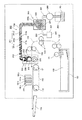
以下、本発明の実施の形態について添付図面を参照して説明する。まず、本発明に係る泡塗布装置を含む本発明に係る画像形成装置の一例について図1を参照して説明する。なお、図1は同画像形成装置の全体構成図である。
この画像形成装置は、被記録媒体である用紙100に液滴を吐出して画像を形成する画像形成手段としての記録ヘッドユニット101と、用紙100を搬送する搬送ベルト102と、用紙100を収容する給紙トレイ103と、画像が形成された用紙100が排紙される排紙トレイ104と、記録ヘッドユニット101よりも用紙搬送方向上流側で被塗布部材である用紙100に泡を塗布する本発明に係る泡塗布装置(被塗布部材に泡を塗布する装置)200とを備えている。
Embodiments of the present invention will be described below with reference to the accompanying drawings. First, an example of an image forming apparatus according to the present invention including a foam coating apparatus according to the present invention will be described with reference to FIG. FIG. 1 is an overall configuration diagram of the image forming apparatus.
The image forming apparatus accommodates a
記録ヘッドユニット101は、液滴を吐出する複数のノズルを用紙幅相当分の長さに配列したノズル列を有するライン型液体吐出ヘッドから構成され、それぞれイエロー(Y)、マゼンタ(M)、シアン(C)、ブラック(K)の各色のインク滴を記録ヘッド101y、101m、101c、101kを備えている。なお、シリアル型画像形成装置として記録ヘッドをキャリッジに搭載する構成ともできる。
The
搬送ベルト102は、無端状ベルトであり、搬送ローラ121とテンションローラ122との間に掛け渡されて周回するように構成している。この搬送ベルト102に対する用紙100の保持は、例えば静電吸着、空気の吸引による吸着などを行う構成とすることやその他の公知の搬送手段を用いることができる。
The
給紙トレイ103に収容された用紙100はピックアップローラ131で1枚ずつ分離されて搬送ローラ132によって給紙されて搬送ローラ対133、134によって搬送路135を介して搬送され、泡塗布装置200によって泡塗布が行われた後、搬送ベルト102上に送り込まれて保持される。
The
そして、搬送ベルト102の周回移動で搬送されながらヘッドユニット101から各色の液滴が吐出されて、泡が塗布された用紙100上に画像が形成され、その後用紙100は排紙トレイ104に排出される。
Then, droplets of each color are ejected from the
一方、泡塗布装置200は、泡にすることが可能な液体又はゲル若しくは液体及びゲル(以下、これらを「処理液」又は「セット剤」と総称する。)201を収容した貯留タンクである容器202と、この容器202から処理液201を圧送するポンプ203と、ポンプ203で供給路204を介して供給された処理液201から泡210aを生成する第1泡生成部205と、第1泡生成部205から泡210aを送る経路である泡搬送経路206と、泡搬送経路206で搬送される泡210aを複数回せん断して小さな泡(小泡)210を生成する第2泡生成部207と、泡210を被記録媒体(用紙100)に塗布する泡塗布部208とを備えている。
On the other hand, the
ここで、泡になり得る処理液201は、用紙100の表面に塗布することで用紙100の表面を改質する改質材である。例えば、処理液201は、予め用紙100(前述したように材質としての紙に限定されない。)にムラなく塗布しておくことで、インクの水分を速やかに用紙100に浸透させると共に色成分を増粘させ、更には乾燥も早めることによって滲み(フェザリング、ブリーディング等)や裏抜けを防止し、生産性(単位時間当たりの画像出力枚数)をあげることを可能にする定着剤(セット剤)である。
Here, the
この処理液201は、組成的には、例えば界面活性剤(アニオン系、カチオン系、ノニオン系のいずれか、若しくはこれらを2種類以上混合させたもの)に対して、水分の浸透を促進するセルロース類(ヒドロキシプロピルセルロース等)とタルク微粉体の様な基剤を加えた溶液等を挙げることができる。更に微粒子を含有することもできる。
In terms of composition, this
第1泡生成部205は、泡生成容器220内の処理液201に対し、高圧空気供給部221から高圧空気222を、高圧空気供給路223を介して供給することによって、泡210aを生成する。この泡生成容器220内で泡210aが生成されて充満することにより、その圧力によって泡搬送経路206を介して泡塗布部208に向けて供給される。なお、泡生成中に処理液201を供給する供給路204を通じて泡210aや処理液201が逆流しないようにポンプ203が供給路204を閉じるようにしている。
The first
第2泡生成部207は、泡搬送経路206内にメッシュ状或いは複数の孔を有する多孔部材などで形成される1又は複数の泡せん断部材241(ここでは、241a、241b、241cの3個)を設けて構成され、泡搬送経路206内を搬送される泡210aを順次せん断して径を小さくした泡210b、210cとし、最終段の泡せん断部材241を通過することで塗布に適した大きさの泡210を形成する。
The second
つまり、第1泡生成部205内の高圧空気の供給によって生成するだけでは塗布及び画像形成に適した所望の微細な泡210が得られないので、高圧空気の供給で生成した大きな径の泡(大泡)210aを泡せん断部材241によってせん断して塗布及び画像形成に適した小さな径の泡(小泡)210に微細化する。
That is, since the desired fine bubbles 210 suitable for coating and image formation cannot be obtained simply by generating by supplying the high-pressure air in the first
このようにすることで、泡を搬送しながら塗布に適した泡210を効率的に生成しながら泡塗布部208に送ることができる。この場合、泡はその堆積力で搬送されるので、第1泡生成部205の泡生成を停止することで泡の搬送も停止される。
By doing so, it is possible to send the
なお、この場合の泡の大きさについて説明しておくと、泡の大きさを区別する「大泡」、「小泡」は、次のように定義する。
大泡:「第1状態の泡」を指す。泡になる液体(若しくはゲル又は両方であっても良い)を用いて生成されているが、後述する「泡」を塗布することによる効果が発揮できない泡を指す。
小泡:「第2状態の泡」を指す。大泡(第1状態の泡)を用いて生成される泡を指し、大泡(第1状態の泡)よりも泡径は小さく、この状態であれば、後述する「泡」を塗布することによる効果を発揮できる泡を指す。
In addition, if the size of the bubble in this case is demonstrated, the "large bubble" and "small bubble" which distinguish the size of a bubble are defined as follows.
Large bubbles: Refers to “first state bubbles”. Although it is generated using a liquid (or a gel or both) that becomes a foam, it refers to a foam that cannot exert the effect of applying a “bubble” described later.
Small bubbles: Refers to “second state bubbles”. This refers to bubbles generated using large bubbles (first state bubbles), and the bubble diameter is smaller than large bubbles (first state bubbles). It refers to the foam that can exert the effect.
この小泡と定義する泡は、前述したように、液体又はゲルがその中に空気などの気体を含んで丸くなったものであり、気体を包む液体の表面張力により形作られ、ある時間立体的形状を保持できるものであって、かさ密度0.05g/cm3以下であり、泡径の分布範囲が10μm〜1mm、平均泡径が100μm以下であることが好ましく、また、泡は単体では丸く形成されるが、複数結合すると表面張力により個々の泡の形状は多面体形状をとるものである。 As described above, a bubble defined as a small bubble is a liquid or gel that contains a gas such as air and is rounded, and is formed by the surface tension of the liquid that encloses the gas. The shape can be maintained, the bulk density is 0.05 g / cm 3 or less, the bubble diameter distribution range is preferably 10 μm to 1 mm, and the average bubble diameter is preferably 100 μm or less. Although formed, if a plurality of bonds are formed, the shape of each bubble takes a polyhedral shape due to surface tension.
また、このような「小泡」は液体ではなく半固体となり、流動性等において固体に近い物性を示すものである。つまり、泡210は処理液201から生成されるものであるが、生成された「泡」自体は「液体」や「ゲル」ではない。
Further, such “small bubbles” are not liquid but semi-solid, and exhibit physical properties close to solid in terms of fluidity. That is, the
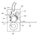
次に、本発明の第1実施形態における泡塗布部について図2の模式的説明図をも参照して説明する。
この泡塗布部208には前述したように微細な泡210が塗布装置上部の供給口から供給され、泡供給口の下方には、供給された泡210を周面に担持して矢示方向に回転する塗布部材(塗布手段)としての塗布ローラ232と、供給された泡210を塗布ローラ232の周面に載せるための攪拌ローラ233とが配置されている。
Next, the foam application part in 1st Embodiment of this invention is demonstrated with reference also to the typical explanatory drawing of FIG.
As described above, the
塗布ローラ232が矢示方向に回転し、塗布ローラ232上に担持された泡210が攪拌ローラ233との間隙を通ることで、泡の厚さが設定される。更に、塗布ローラ232の周面に対向して攪拌ローラ233よりも下流側(塗布ローラ回転方向で)に泡厚さ規制ローラ234が配置されて、より微小の厚みに調整される。泡厚さ規制ローラ234と塗布ローラ232との距離は、攪拌ローラ233と塗布ローラ232との距離よりも小さく設定されている。
The
この泡厚さ規制ローラ234よりも下流側には、塗布ローラ232による用紙100への泡塗布位置で塗布ローラ232に対向して用紙100を塗布ローラ232の周面側に加圧する加圧手段である加圧ローラ235が配置されている。この加圧ローラ235は、常に塗布ローラ233に接している構成、あるいは、用紙100が通るときのみ塗布ローラ233に接する方向に移動される構成のいずれでもよい。
On the downstream side of the foam
さらに、塗布ローラ232上に塗布後も残存する余剰泡211を掻き取って清掃する清掃部材236と、清掃部材236で掻き取られた余剰泡212を加熱する加熱部材237とで構成される清掃手段を備えている。なお、清掃部材236は塗布ローラ232に当接して配置されており、塗布ローラ232が回転することで余剰泡211が清掃部材236で掻き取られる。また、清掃部材236及び加熱手段237による清掃が行われる部分を「清掃部」という。
Further, a cleaning means comprising a cleaning
このように構成した泡塗布部208においては、泡210を塗布ローラ232の周面に供給し、被記録媒体幅(用紙幅:用紙搬送方向の幅)よりも広い幅で泡210の膜が形成される。これは用紙100の幅方向全域に塗布するためである。そして、この塗布ローラ232が泡210を周面に担持して矢示方向に回転することで、塗布ローラ232上の泡210の膜厚が、攪拌ローラ233、泡厚さ規制ローラ234と塗布ローラ232の周面とのギャップで規定される厚み(塗布膜厚という。)に規制され、塗布ローラ232の周面の泡210が均一な塗布膜厚に調整された後、塗布ローラ232と加圧ローラ235との間を矢示方向に搬送される用紙100の表面に泡310が転移して塗布される。泡210が塗布された用紙100は記録ヘッドユニット101による画像形成位置に送られる。
In the
このように、用紙100の表面に泡210を塗布することによって、空気を大量に含むことで微量塗布が可能となって、塗布の均一化を図れ、速乾性が向上し、滲み、裏写り、濃度ムラ等のない良質な画像を出力することができる。
In this way, by applying the
つまり、処理液を泡にして塗布することで、液体やミスト状の処理液と比べて、次のような利点(効果)がある。
(1)泡は空気を大量に含むため、微量塗布が可能である。
(2)泡は固体に近いため、塗布してから削りとる等で塗布膜厚を容易に調整することができ、又、塗布手段から紙への塗布時に塗布手段からの剥離性が良いため、均一塗布が可能である。
(3)泡は紙の繊維に水分が浸透しにくいため、紙にシワやカールが発生しにくい。
That is, by applying the treatment liquid in the form of foam, there are the following advantages (effects) compared to the liquid or mist-like treatment liquid.
(1) Since foam contains a large amount of air, it can be applied in a small amount.
(2) Since the foam is close to solid, the coating film thickness can be easily adjusted by applying and scraping, etc., and since the peelability from the coating means is good at the time of coating from the coating means to the paper, Uniform application is possible.
(3) Since water does not easily penetrate into the fibers of the paper, wrinkles and curls are unlikely to occur on the paper.
さらに、このように被記録媒体の処理剤として「泡」のものを用いることは、液体の処理剤に比べて特に高速での記録、処理時に格別の効果を有する。例えば、連帳機のように、連続紙に高速で印刷を行う場合、処理剤の塗布も記録動作に追いつくためにローラ等を高速に回転させて塗布を行う必要がある。 Furthermore, the use of “foam” as the processing agent for the recording medium in this way has a special effect during recording and processing at a particularly high speed as compared with a liquid processing agent. For example, when printing on continuous paper at a high speed as in a continuous book machine, it is necessary to rotate the roller or the like at high speed in order to catch up with the recording operation.
このような記録が毎分100m程度を超えるスピードになると、ローラの高速回転により発生する遠心力もきわめて大きくなり、液体の処理剤では、処理剤がローラ表面から引き離され飛散してしまい、被記録媒体に塗布される量が著しく低下してしまうという不具合がある。液体の処理剤を使用してこのような不具合を解決するためには、液体の粘度を上げてローラ表面から飛散しにくくすることも考えられるが、このような高粘度液体は薄膜で塗布することが困難になり、しかも給液、排液動作の負荷が大きくなって搬送用のポンプの大型化や装置の複雑化を招くことになる。 When such a recording speed exceeds about 100 m / min, the centrifugal force generated by the high-speed rotation of the roller becomes very large, and in the case of a liquid processing agent, the processing agent is separated from the roller surface and scattered. There is a problem that the amount applied to the film is significantly reduced. In order to solve such problems by using a liquid processing agent, it may be possible to increase the viscosity of the liquid and make it difficult to scatter from the roller surface, but such a high viscosity liquid should be applied as a thin film. In addition, the load of the liquid supply / drainage operation increases, leading to an increase in the size of the transport pump and the complexity of the apparatus.
これに対して、処理液から生成した「泡」は、搬送時は通常の低粘度液体であり、搬送負荷が少ない上に、ローラ上では発泡させた状態で半固体の性質を示すため、ローラの高速回転にも追随して飛散することがない。また、被記録媒体への薄膜塗布に有利であることは前述のとおりである。さらに、塗布後の残泡はヒータの加熱等で消泡することで容易に低粘度液体として再回収でき、液体の処理剤塗布の高速塗布における問題点をすべて解決することができる。 On the other hand, the “bubbles” generated from the processing liquid are ordinary low-viscosity liquids during transport, have a small transport load, and exhibit a semi-solid property in a foamed state on the roller. The high-speed rotation will not follow and scatter. Further, as described above, it is advantageous for thin film coating on a recording medium. Further, the remaining bubbles after application can be easily recovered as a low-viscosity liquid by defoaming by heating with a heater or the like, and all problems in high-speed application of liquid treatment agent application can be solved.
このような泡塗布の長所は、処理液の種類に依存せず、同様な効果が得られる。なお、処理液は紙粉を抑える効果を持つことが好ましく、また、用紙の地肌色を変える効果があっても良い。 The advantages of such foam application do not depend on the type of treatment liquid, and the same effect can be obtained. The treatment liquid preferably has an effect of suppressing paper dust, and may have an effect of changing the background color of the paper.
ここで、塗布ローラ232から用紙100上に塗布されなかった泡210は余剰泡211となってそのまま塗布ローラ232上に残存する。つまり、塗布ローラ232上には用紙の幅方向の全域に塗布するために用紙幅よりも広い幅で泡210の膜が形成されているため、用紙100上に塗布されなかった泡210は余剰泡211としてそのまま塗布ローラ232上に残ることになり、また、複数枚の用紙に塗布する場合、用紙と用紙の間(紙間)でも余剰泡211が生じることになる。
Here, the
このような余剰泡211を放置していると、余剰泡211が乾燥し、処理液成分が固着してしまうことになる。処理液成分が固着すると、泡塗布性能の低下(塗布ムラの発生)や駆動系の性能低下などの不具合が発生する。 If such surplus bubbles 211 are left untreated, the surplus bubbles 211 are dried and the processing liquid components are fixed. When the treatment liquid component is fixed, problems such as a decrease in foam application performance (occurrence of application unevenness) and a decrease in drive system performance occur.
そこで、ここでは、余剰泡210を清掃するための清掃部材236を塗布ローラ232上に設けて塗布ローラ232が回転することで余剰泡211を掻き取って清掃するようにしている。掻き取られた余剰泡211は清掃部材236の近傍に溜まるが、これも放置すると余剰泡212が累積して用紙100にまで付着してしまうおそれがあることから、この余剰泡212をさらに処理する必要がある。
Therefore, here, a cleaning
ただし、泡は固体のような性質を持っており、泡そのままでは搬送処理するのが困難である。そこで、泡の性質を利用した余剰泡211の処理を行う。つまり、泡は、液体の薄膜で空気を取り囲んだ微小球の集合体となっており、温度変化により泡の状態も変化する。泡を高温にすると中の空気が膨張するため、液体外壁が内側からの圧力に耐え切れず、割れて液化する。このような泡の性質を利用する。 However, the foam has properties such as a solid, and it is difficult to carry and process the foam as it is. Therefore, the surplus bubbles 211 are processed using the properties of the bubbles. In other words, the bubbles are aggregates of microspheres surrounding the air with a liquid thin film, and the state of the bubbles also changes due to temperature change. When the foam is heated to a high temperature, the air inside expands, so that the liquid outer wall cannot withstand the pressure from the inside and breaks and liquefies. Utilizing the nature of such bubbles.
そこで、清掃部材236の近傍に余剰泡212を加熱する加熱手段237を設けている。加熱手段237によって直接的又は間接的に余剰泡212を加熱することで、余剰泡212は液化して処理液に還元され体積を縮小させることができる。
Therefore, heating means 237 for heating the surplus bubbles 212 is provided in the vicinity of the cleaning
ここでは、加熱手段237はブレード状のヒータで構成しているが、赤外線による局所加熱や高温エアーの吹き付け等による他の手段でも実施できる。 Here, the heating means 237 is constituted by a blade-like heater, but other means such as local heating by infrared rays or high-temperature air blowing can also be implemented.
次に、本発明の第2実施形態における泡塗布部について図3の模式的説明図をも参照して説明する。
ここでは、清掃部材236の近傍に加熱した高温のエアー238を吹き付けいている。これにより、余剰泡212を液化させることができる。
Next, the foam application part in 2nd Embodiment of this invention is demonstrated with reference also to the typical explanatory drawing of FIG.
Here, heated
次に、本発明の第3実施形態における泡塗布部について図4の模式的説明図をも参照して説明する。
ここでは、加圧ローラ235側に清掃部材236と、清掃部材236を加熱することで掻き取られた余剰泡212を加熱する加熱手段237を設けている。つまり、余剰泡211は塗布ローラ232側だけでなく加圧ローラ235側にも転移付着するので、加圧ローラ235側の余剰泡を清掃部材236で掻き取って清掃し、掻き取られた余剰泡212を加熱部材237による加熱で液化する。
Next, the foam application part in 3rd Embodiment of this invention is demonstrated with reference also to the typical explanatory drawing of FIG.
Here, on the
次に、本発明の第4実施形態における泡塗布部について図5の模式的説明図をも参照して説明する。
ここでは、前記第1実施形態において、清掃部材236によって清掃部に対応して液化された処理液に還元された液体(還元処理液)を受ける回収液受け手段である回収皿238を設け、液化された余剰泡(還元処理液)を貯留して回収経路239を通って回収できるようにしている。回収された還元処理液はそのまま廃棄することもできるし、回収経路239を通じて貯留タンクである容器202に戻すことで処理液として再び使用することもができる。また、この際に加熱により揮発する処理液の溶媒成分を補って処理液成分を調整してから、容器202に戻す構成とすることもできる。
Next, the foam application part in 4th Embodiment of this invention is demonstrated with reference also to the typical explanatory drawing of FIG.
Here, in the first embodiment, a
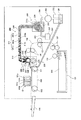
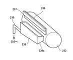
次に、本発明の第5実施形態について図6ないし図8を参照して説明する。なお、図6は図1と同様な全体構成図、図7は同実施形態の泡塗布部の模式的説明図、図8は同じく塗布部の斜視説明図である。
ここでは、前記第4実施形態と同様に、清掃部材236によって清掃部に対応して液化された処理液に還元された液体(還元処理液)を受ける回収皿238を設け、液化された余剰泡(還元処理液)を貯留して回収経路239を通って回収できるようにしている。そして、回収皿238は底面238aを傾斜させた形状とし、回収経路239の一端部は回収皿底面238aの最も低い位置に接続され、回収経路239の他端部は貯留タンクである容器202に接続されている。
Next, a fifth embodiment of the present invention will be described with reference to FIGS. 6 is an overall configuration diagram similar to FIG. 1, FIG. 7 is a schematic explanatory view of a foam application unit of the embodiment, and FIG. 8 is a perspective explanatory view of the application unit.
Here, as in the fourth embodiment, a
これにより、回収皿238で回収された還元処理液を回収経路239を通じて容器202に戻すことで処理液として再び使用できるようにしている。
Thereby, the reduction processing liquid recovered by the
次に、本発明の第6実施形態における泡塗布部について図9の模式的説明図をも参照して説明する。
ここでは、回収皿238の下面に加熱手段237を設けている。この構成の場合、清掃部材236が熱により劣化することを防止できるし、加熱部材が間接的に塗布ローラ232と接触することを防止できるため、塗布ローラ上の泡の品質を一定に制御しやすくなる。余剰泡212は清掃部材236に蓄積され、自重で回収皿238に落下し、ここではじめて加熱により液化される。
Next, the foam application part in 6th Embodiment of this invention is demonstrated with reference also to the typical explanatory drawing of FIG.
Here, a heating means 237 is provided on the lower surface of the
次に、本発明の第7実施形態における泡塗布部について図10の模式的説明図をも参照して説明する。
ここでは、塗布ローラ232の内部に清掃部材236に対向してヒータなどの加熱手段237を配置している。なお、塗布ローラ232は中空ローラであって加熱手段237は塗布ローラ232の回転に伴って回転しない。この構成によれば、清掃部材236の位置で塗布ローラ232上の余剰泡211が消泡し、回収皿238に液滴として回収されるので、塗布ローラ232上に余剰泡211が固着することが防止される。
Next, the foam application part in 7th Embodiment of this invention is demonstrated with reference also to the typical explanatory drawing of FIG.
Here, heating means 237 such as a heater is disposed inside the
次に、この画像形成装置の制御部の概要について図11のブロック説明図を参照して説明する。
この制御部は、本画像形成装置のシステム制御を行うCPU801と、CPU801が実行するプログラムなどの情報を格納するROM802と、ワーキングエリアとして使用するRAM803と、オペレータが各種設定等を行うため操作表示部804と、紙サイズ検知やジャム検知等を行う各種センサ805と、各種モータ等806と、各種センサ805及び各種モータ等806への出力制御信号を行うI/O807と、画像読取り装置(スキャナ)808を制御する読取り制御部809と、プロッタ部(印字機構部)810を制御する印字制御部811と、電話回線とのI/F制御を行う網制御装置812の制御も含めて、各種ファクシミリ通信制御を行う通信制御部813と、泡塗布装置200の制御を行う泡塗布制御部814等を備えている。
Next, an outline of the control unit of the image forming apparatus will be described with reference to a block diagram of FIG.
The control unit includes a
泡塗布制御部814は、泡塗布装置200の泡生成部205を制御して泡210の生成、貯留、塗布ローラ232に対する供給などの制御を行うとともに、清掃手段を構成する加熱手段237のオン/オフ制御をする。
The foam
なお、各種センサ805には、環境条件を検出する温度/湿度検知手段、処理液201が容器202内にあるか否かを検知する処理液エンド検知手段などが含まれる。
The
そこで、泡塗布制御部による清掃(消泡)動作の制御の第1例について図12のフロー図を参照して説明する。
先ず、前回の清掃動作からの経過時間が所定時間(例えば30分)になる(所定時間放置)と、印刷ジョブを実行中か否かを判別し、印刷ジョブを実行中でなければ、そのまま清掃手段の加熱手段237を駆動(オン)制御して加熱させることで清掃動作を行う。これに対して、印刷ジョブを実行中であれば、ジョブ終了を待って、ジョブが終了した後、清掃動作を行う。
A first example of control of the cleaning (defoaming) operation by the foam application control unit will be described with reference to the flowchart of FIG.
First, when the elapsed time from the previous cleaning operation reaches a predetermined time (for example, 30 minutes) (leaving for a predetermined time), it is determined whether or not the print job is being executed. A cleaning operation is performed by driving (ON) the heating means 237 of the means and heating it. On the other hand, if the print job is being executed, the cleaning operation is performed after the job is completed after the job is completed.
このように印刷ジョブ終了後に清掃動作を行うのは、ユーザが使用しているときにはダウンタイムとなる清掃は行わない方がよい、つまり、ダウンタイムを少なくするためである。 The reason why the cleaning operation is performed after the end of the print job is that it is better not to perform the downtime cleaning when the user is using it, that is, to reduce the downtime.
次に、泡塗布制御部による清掃動作の制御の第2例について図13のフロー図を参照して説明する。
電源OFF指示信号が入力されると、清掃手段の加熱手段237を駆動制御して清掃動作を行い、清掃完了後、清掃終了信号を出力する。これを受けて、制御部のCPU801は装置の電源をシャットダウンする。
Next, a second example of the cleaning operation control by the foam application controller will be described with reference to the flowchart of FIG.
When the power OFF instruction signal is input, the
このように装置の電源をOFFするときには、次に電源がONされるまでの時間を予測することができないので、電源OFF時に清掃(及び消泡)を行っておくことで余剰泡が塗布ローラ232上で長時間放置されるのを防止することができる。 When the power of the apparatus is turned off in this way, it is impossible to predict the time until the power is turned on next time, so that the excess foam is removed by cleaning (and defoaming) when the power is turned off. It can be prevented from being left for a long time.
なお、上記実施形態では泡塗布装置が画像形成前の用紙に対して泡を塗布する構成で説明しているが、記録ヘッドユニットの下流側に泡塗布装置を配置し、画像形成が行われた用紙上に泡を塗布する構成とすることもできる。また、上記実施形態では、泡にすることが可能な液体から泡を生成して塗布する例で説明しているが、本発明を、泡にすることが可能なゲルから泡を生成して被塗布部材に塗布する装置、この装置を備える画像形成装置にも適用することができる。 In the above embodiment, the foam application device is described as applying foam to the paper before image formation. However, the foam application device is arranged on the downstream side of the recording head unit to perform image formation. It can also be set as the structure which apply | coats a bubble on a paper. Moreover, although the said embodiment demonstrated the example which produces | generates and apply | coats foam from the liquid which can be made into foam, this invention produces | generates foam from the gel which can be made into foam, and is covered. The present invention can also be applied to an apparatus for applying to an application member and an image forming apparatus including this apparatus.
また、本発明に係る泡塗布装置は、例えば電子写真方式の画像形成装置にも適用することができる。例えば、紙等の媒体上のトナー等の樹脂を含有する微粒子を乱すことなく、かつ当該樹脂微粒子を付着した媒体に定着液を泡化(以下「定着泡」という)して塗布することにより、塗布後には素早く樹脂微粒子の媒体への定着が行われ、更に媒体に残油感が発生しない定着方法及び定着装置、並びに画像形成方法及び画像形成装置にも適用できる。 The foam coating apparatus according to the present invention can also be applied to, for example, an electrophotographic image forming apparatus. For example, without disturbing fine particles containing a resin such as toner on a medium such as paper, and applying a foamed fixer (hereinafter referred to as “fixing bubbles”) to the medium to which the fine resin particles are adhered, After application, the resin fine particles are quickly fixed on the medium, and the present invention can also be applied to a fixing method and a fixing device, and an image forming method and an image forming apparatus in which a residual oil feeling does not occur on the medium.
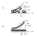
そこで、電子写真方式の画像形成装置に適用した場合の例について図14及び図15を参照して説明する。なお、図14及び図15はローラ塗布手段においてローラ塗布面と未定着樹脂微粒子が接する部分の拡大説明図であり、図14は塗布ローラと記録媒体との接触面での加圧が相対的に高い場合、図15は同加圧が相対的に低い場合である。また、塗布ローラ1011の回転方向及び被塗布部材としての記録媒体1010の移動方向はいずれも図中の矢印方向とする。
An example of application to an electrophotographic image forming apparatus will be described with reference to FIGS. 14 and 15 are enlarged explanatory views of a portion where the roller coating surface and the unfixed resin fine particles are in contact with each other in the roller coating unit, and FIG. 14 shows relative pressure applied on the contact surface between the coating roller and the recording medium. When the pressure is high, FIG. 15 shows the case where the pressure is relatively low. In addition, both the rotation direction of the
まず、塗布ローラ1011と記録媒体1010との接触面での加圧が高い場合、図14(a)に示す例では、塗布ローラ1011の塗布面で定着泡1012は気泡1013の単層構造となっていることから、気泡自身が表面張力により塗布ローラ1011の塗布面に付着しやすく、記録媒体1010上の樹脂微粒子(未定着トナー)1015の層へ定着泡1012が不均一にしか塗布されず、樹脂微粒子1015が気泡1013に吸着して塗布ローラ1011の塗布面にオフセットしてしまう。
First, when the pressure on the contact surface between the
一方、図14(b)に示すように、塗布ローラ1011の塗布面で定着泡1012が複数層の気泡層構造である場合、凹凸を有する未定着トナー1015の面への気泡の埋め込みが可能となり、定着泡1012は気泡1013の層間で分離しやすくなり、トナー層に均一に塗布可能となり、トナーオフセットを極めて生じにくくすることができる。
On the other hand, as shown in FIG. 14B, when the
したがって、塗布ローラ1011と記録媒体1010との接触面での加圧が高い場合、塗布ローラ1011に未定着トナー1015がオフセットしないようにするためには、予め生成する気泡の平均的な大きさを測定しておき、気泡層が複数層となるように、塗布ローラ1011上の定着泡層の膜厚を気泡層の複数層分の厚みになるように制御すれば、塗布ローラ1011上には必ず複数層の気泡層からなる定着泡層が形成され、トナーオフセットの防止が可能となる。
Therefore, when the pressure on the contact surface between the
また、塗布ローラ1011と記録媒体1010との接触面での加圧が低い場合、図15(a)に示すように、塗布ローラ1011の塗布面で定着泡1012は気泡1013の単層構造となっているため、凹凸を有する未定着トナー1015の面への気泡が付着しやすくなり、塗布ローラ1011の面から気泡層が剥離し、定着泡1012は未定着トナー1015に塗布される。
When the pressure on the contact surface between the
一方、図15(b)に示すように、塗布ローラ1011の塗布面で定着泡1012が複数層の気泡層構造である場合、気泡1013どうしの結合が強いため、気泡1013は塗布ローラ1011側に残りやすく、逆に未定着トナー1015が気泡1013に付着して、結果として塗布ローラ1011の面に未定着トナー1015がオフセットする。
On the other hand, as shown in FIG. 15B, when the
したがって、塗布ローラ1011と記録媒体1010との接触面での加圧が低い場合、予め気泡の平均的な大きさを測定しておき、塗布ローラ面で単層の気泡層構造の定着泡となるように定着泡層厚みを制御すれば、塗布ローラ上には単層の気泡層構造の定着泡膜が形成され、高加圧力条件でトナーオフセットを防止できる。また、塗布ローラ1011に未定着トナー1015がオフセットしないようにするためには、塗布ローラ1011上の気泡層が厚すぎると塗布ローラ1011と記録媒体1010との接触部に気泡層の流動が生じ、トナー粒子がその流れに沿って移動してしまし、画像が流れる不具合が発生するので、流動性が生じない範囲に定着泡層の膜厚を制御することが好ましい。
Therefore, when the pressure on the contact surface between the
このように、定着泡に含有される気泡の大きさ、加圧力に応じて、定着泡層の膜厚を制御することで、塗布ローラのような接触塗布手段へのトナーオフセットや画像流れを防止し、極めて微小の塗布による定着を可能とすることができる。 In this way, by controlling the film thickness of the fixing foam layer according to the size and pressure of the bubbles contained in the fixing foam, toner offset and image flow to the contact application means such as the application roller can be prevented. In addition, fixing by extremely minute application can be made possible.
すなわち、樹脂微粒子の少なくとも一部を溶解又は膨潤させて樹脂微粒子を軟化させる軟化剤を用い、接触塗布手段にて媒体上の当該樹脂微粒子に定着液を塗布することで当該樹脂微粒子を媒体に定着する方法であり、当該定着液を該媒体上の当該樹脂微粒子表面に付与するときに、当該微粒子に定着液が接する塗布で、当該定着液が気泡を含有した泡状形態とし、更に当該定着泡層の膜厚を加圧力に応じて制御することにより、塗布ローラのような接触塗布手段へのトナーオフセットや画像流れを防止し、極めて微小の塗布による定着を可能とすることができる。また、樹脂微粒子として、電子写真技術に用いるトナー微粒子に対する効果が高く、この樹脂微粒子の層厚に応じて定着泡層の膜厚を制御することでオフセットや画像流れを防止できる。 That is, using a softening agent that softens the resin fine particles by dissolving or swelling at least a part of the resin fine particles, the fixing solution is applied to the resin fine particles on the medium by contact coating means, and the resin fine particles are fixed to the medium. When the fixing solution is applied to the surface of the fine resin particles on the medium, the fixing solution is in the form of bubbles containing bubbles by coating the fine particles in contact with the fine particles. By controlling the film thickness of the layer according to the applied pressure, it is possible to prevent toner offset and image flow to a contact application means such as an application roller, and to enable fixing by extremely minute application. Further, the resin fine particles are highly effective for the toner fine particles used in the electrophotographic technology, and offset and image flow can be prevented by controlling the film thickness of the fixing foam layer according to the layer thickness of the resin fine particles.
100…被記録媒体(用紙)
101…記録ヘッドユニット
102…搬送ベルト
103…給紙トレイ
200…泡塗布装置
201…処理液(泡になる液体又はゲル若しくは液体及びゲル)
205…第1泡生成部
206…泡搬送経路
207…第2泡生成部
208…泡塗布部
210…泡
232…塗布ローラ
235…加圧ローラ
236…清掃部材
237…加熱手段
238…回収皿
239…回収経路
100: Recording medium (paper)
DESCRIPTION OF
DESCRIPTION OF
Claims (5)
前記被記録媒体又は被記録媒体に塗布するための中間部材に対して液体及びゲルの少なくともいずれかを泡にして塗布する泡塗布手段と、を備え、
前記泡塗布手段は、
前記泡を塗布する塗布手段と、
前記泡塗布手段には前記塗布手段で塗布されずに残った余剰泡を加熱して清掃する清掃手段と、を備えている
ことを特徴とする画像形成装置。 Image forming means for forming an image on a recording medium;
A foam application means for applying at least one of a liquid and a gel to the recording medium or an intermediate member for application to the recording medium,
The foam applying means is
Application means for applying the foam;
An image forming apparatus, comprising: a cleaning unit that heats and cleans excess foam remaining without being applied by the applying unit.
前記泡を塗布する塗布手段と、
前記塗布手段で塗布されずに残った余剰泡を加熱して清掃する清掃手段と、を備えている
ことを特徴とする泡塗布装置。 In a foam application device for applying foam to a member to be coated by foaming at least one of liquid and gel,
Application means for applying the foam;
And a cleaning means for heating and cleaning excess foam remaining without being applied by the applying means.
Priority Applications (1)
| Application Number | Priority Date | Filing Date | Title |
|---|---|---|---|
| JP2009084978A JP5476767B2 (en) | 2008-09-02 | 2009-03-31 | Image forming device, foam coating device |
Applications Claiming Priority (3)
| Application Number | Priority Date | Filing Date | Title |
|---|---|---|---|
| JP2008225223 | 2008-09-02 | ||
| JP2008225223 | 2008-09-02 | ||
| JP2009084978A JP5476767B2 (en) | 2008-09-02 | 2009-03-31 | Image forming device, foam coating device |
Publications (2)
| Publication Number | Publication Date |
|---|---|
| JP2010083132A true JP2010083132A (en) | 2010-04-15 |
| JP5476767B2 JP5476767B2 (en) | 2014-04-23 |
Family
ID=42247555
Family Applications (1)
| Application Number | Title | Priority Date | Filing Date |
|---|---|---|---|
| JP2009084978A Expired - Fee Related JP5476767B2 (en) | 2008-09-02 | 2009-03-31 | Image forming device, foam coating device |
Country Status (1)
| Country | Link |
|---|---|
| JP (1) | JP5476767B2 (en) |
Cited By (4)
| Publication number | Priority date | Publication date | Assignee | Title |
|---|---|---|---|---|
| CN102371756A (en) * | 2010-08-17 | 2012-03-14 | 富士胶片株式会社 | Foam coating device and image forming device |
| CN102785490A (en) * | 2011-05-17 | 2012-11-21 | 佳能株式会社 | Printing apparatus that cleans fixing device, method of controlling the printing apparatus, and storage medium |
| CN109338732A (en) * | 2018-09-29 | 2019-02-15 | 东阳市金茂塑胶有限公司 | A kind of environmental protection flame retardant PVC artificial leather preparation facilities and method |
| CN114953778A (en) * | 2021-02-26 | 2022-08-30 | 株式会社理光 | Coating device, liquid discharge apparatus, and printer |
Citations (4)
| Publication number | Priority date | Publication date | Assignee | Title |
|---|---|---|---|---|
| JPH07323554A (en) * | 1994-06-01 | 1995-12-12 | Sharp Corp | Ink jet recorder |
| JPH0994561A (en) * | 1995-09-29 | 1997-04-08 | Toyota Motor Corp | Method for recovering foaming agent and device therefor |
| JP2006347081A (en) * | 2005-06-17 | 2006-12-28 | Fuji Xerox Co Ltd | Method and equipment for forming pattern |
| JP2007219105A (en) * | 2006-02-16 | 2007-08-30 | Ricoh Co Ltd | Fixing device, fixing method, image forming apparatus, image forming method, and fixing solution |
-
2009
- 2009-03-31 JP JP2009084978A patent/JP5476767B2/en not_active Expired - Fee Related
Patent Citations (4)
| Publication number | Priority date | Publication date | Assignee | Title |
|---|---|---|---|---|
| JPH07323554A (en) * | 1994-06-01 | 1995-12-12 | Sharp Corp | Ink jet recorder |
| JPH0994561A (en) * | 1995-09-29 | 1997-04-08 | Toyota Motor Corp | Method for recovering foaming agent and device therefor |
| JP2006347081A (en) * | 2005-06-17 | 2006-12-28 | Fuji Xerox Co Ltd | Method and equipment for forming pattern |
| JP2007219105A (en) * | 2006-02-16 | 2007-08-30 | Ricoh Co Ltd | Fixing device, fixing method, image forming apparatus, image forming method, and fixing solution |
Cited By (6)
| Publication number | Priority date | Publication date | Assignee | Title |
|---|---|---|---|---|
| CN102371756A (en) * | 2010-08-17 | 2012-03-14 | 富士胶片株式会社 | Foam coating device and image forming device |
| CN102785490A (en) * | 2011-05-17 | 2012-11-21 | 佳能株式会社 | Printing apparatus that cleans fixing device, method of controlling the printing apparatus, and storage medium |
| CN109338732A (en) * | 2018-09-29 | 2019-02-15 | 东阳市金茂塑胶有限公司 | A kind of environmental protection flame retardant PVC artificial leather preparation facilities and method |
| CN109338732B (en) * | 2018-09-29 | 2021-08-17 | 东阳市金茂塑胶有限公司 | Preparation device and method of environment-friendly flame-retardant PVC artificial leather |
| CN114953778A (en) * | 2021-02-26 | 2022-08-30 | 株式会社理光 | Coating device, liquid discharge apparatus, and printer |
| US20220274434A1 (en) * | 2021-02-26 | 2022-09-01 | Ricoh Company, Ltd. | Coating device, liquid discharge apparatus, and printer |
Also Published As
| Publication number | Publication date |
|---|---|
| JP5476767B2 (en) | 2014-04-23 |
Similar Documents
| Publication | Publication Date | Title |
|---|---|---|
| JP5347527B2 (en) | Image forming device, foam coating device | |
| JP5217990B2 (en) | Image forming device, foam coating device | |
| JP5321026B2 (en) | Image forming device, foam coating device | |
| JP5476767B2 (en) | Image forming device, foam coating device | |
| JP5369687B2 (en) | Image forming apparatus and foam coating apparatus | |
| JP5359368B2 (en) | Image forming device, foam coating device | |
| JP5181945B2 (en) | Image forming device, foam coating device | |
| JP5206552B2 (en) | Image forming device, foam coating device | |
| JP5182083B2 (en) | Image forming apparatus | |
| JP5234421B2 (en) | Image forming apparatus | |
| JP5272854B2 (en) | Image forming device, foam coating device | |
| JP5212081B2 (en) | Image forming device, foam coating device | |
| JP5288034B2 (en) | Image forming apparatus | |
| JP5332817B2 (en) | Image forming device, foam coating device | |
| JP5470971B2 (en) | Image forming device, foam coating device | |
| JP5375185B2 (en) | Image forming device, foam coating device | |
| JP5321027B2 (en) | Image forming device, foam coating device | |
| JP5182085B2 (en) | Image forming apparatus | |
| JP5347645B2 (en) | Image forming device, foam coating device | |
| JP5434189B2 (en) | Image forming device, foam coating device | |
| JP5581821B2 (en) | Image forming apparatus and processing liquid coating apparatus | |
| JP5218070B2 (en) | Image forming apparatus and foam coating apparatus | |
| JP5257076B2 (en) | Image forming apparatus | |
| JP5182084B2 (en) | Image forming apparatus | |
| JP5146833B2 (en) | Image forming apparatus |
Legal Events
| Date | Code | Title | Description |
|---|---|---|---|
| A621 | Written request for application examination |
Free format text: JAPANESE INTERMEDIATE CODE: A621 Effective date: 20120313 |
|
| A521 | Written amendment |
Free format text: JAPANESE INTERMEDIATE CODE: A523 Effective date: 20120622 |
|
| A977 | Report on retrieval |
Free format text: JAPANESE INTERMEDIATE CODE: A971007 Effective date: 20130213 |
|
| A131 | Notification of reasons for refusal |
Free format text: JAPANESE INTERMEDIATE CODE: A131 Effective date: 20130219 |
|
| A521 | Written amendment |
Free format text: JAPANESE INTERMEDIATE CODE: A523 Effective date: 20130412 |
|
| TRDD | Decision of grant or rejection written | ||
| A01 | Written decision to grant a patent or to grant a registration (utility model) |
Free format text: JAPANESE INTERMEDIATE CODE: A01 Effective date: 20140114 |
|
| A61 | First payment of annual fees (during grant procedure) |
Free format text: JAPANESE INTERMEDIATE CODE: A61 Effective date: 20140127 |
|
| R151 | Written notification of patent or utility model registration |
Ref document number: 5476767 Country of ref document: JP Free format text: JAPANESE INTERMEDIATE CODE: R151 |
|
| LAPS | Cancellation because of no payment of annual fees |