JP5288034B2 - Image forming apparatus - Google Patents
Image forming apparatus Download PDFInfo
- Publication number
- JP5288034B2 JP5288034B2 JP2012184625A JP2012184625A JP5288034B2 JP 5288034 B2 JP5288034 B2 JP 5288034B2 JP 2012184625 A JP2012184625 A JP 2012184625A JP 2012184625 A JP2012184625 A JP 2012184625A JP 5288034 B2 JP5288034 B2 JP 5288034B2
- Authority
- JP
- Japan
- Prior art keywords
- liquid
- foam
- image forming
- forming apparatus
- generating
- Prior art date
- Legal status (The legal status is an assumption and is not a legal conclusion. Google has not performed a legal analysis and makes no representation as to the accuracy of the status listed.)
- Expired - Fee Related
Links
Images


Description
本発明は画像形成装置に関する。 The present invention relates to an image forming apparatus.
プリンタ、ファクシミリ、複写装置、これらの複合機等の画像形成装置として、例えば、記録液の液滴を吐出する液体吐出ヘッドで構成した記録ヘッドを用いて、被記録媒体(以下「用紙」ともいうが材質を限定するものではなく、また、媒体、記録媒体、転写材、記録紙なども同義で使用する。)を搬送しながら、液滴を用紙に付着させて画像形成(記録、印刷、印写、印字も同義語で用いる。)を行うものがある。 As an image forming apparatus such as a printer, a facsimile machine, a copying machine, or a multifunction machine of these, for example, a recording head composed of a liquid ejection head that ejects liquid droplets of a recording liquid is used, and a recording medium (hereinafter also referred to as “paper”). However, the material is not limited, and a medium, a recording medium, a transfer material, a recording paper, etc. are also used synonymously.) While transporting, droplets adhere to the paper to form an image (recording, printing, marking). Copy and print are also used synonymously.)
なお、「画像形成装置」は、紙、糸、繊維、布帛、皮革、金属、プラスチック、ガラス、木材、セラミックス等の媒体に液滴を着弾させて画像形成を行う装置を意味し、また、「画像形成」とは、文字や図形等の意味を持つ画像を媒体に対して付与することだけでなく、パターン等の意味を持たない画像を媒体に付与することをも意味する。また、記録液とは、インクに限るものではなく、上記の意味での画像形成を行うことができる、吐出時に液滴化するものであればよい。 The “image forming apparatus” means an apparatus that forms an image by landing droplets on a medium such as paper, thread, fiber, cloth, leather, metal, plastic, glass, wood, ceramics, etc. “Image formation” not only means that an image having a meaning such as a character or a figure is imparted to the medium but also an image having no meaning such as a pattern is imparted to the medium. Further, the recording liquid is not limited to ink, and any recording liquid can be used as long as it can form an image in the above sense and can be formed into droplets at the time of ejection.
このような液体吐出方式の画像形成装置においては、色材を含む記録液(以下「インク」という。)を液滴化して画像形成を行うために、液滴で形成さえるドットがひげ状に乱れるフェザリング、異なる色のインク滴が隣接して用紙に打たれた場合に、各色が相互に混ざり合って色境界が不鮮明になるカラーブリード等の不具合が生じることがあり、更に印字後の紙上の液滴が乾くまでに時間がかかるという問題がある。 In such a liquid ejection type image forming apparatus, since a recording liquid containing a color material (hereinafter referred to as “ink”) is formed into droplets to form an image, the dots formed by the droplets are disturbed in a whisker shape. When ink drops of different colors are struck on the paper adjacent to each other, problems such as color bleed may occur where the colors mix with each other and the color boundary becomes unclear. There is a problem that it takes time for the droplets to dry.
そこで、従来から特許文献1に記載されているように印字前又は印字後に加熱手段を用いて滲み防止、印字後のインク乾燥を促進することが行われる。
また、特許文献2に記載されているようにインクと反応して滲み防止を促す前処理液を塗布ローラで塗布したり、特許文献3に記載されているように前処理液を液体吐出ヘッドからミスト状に吐出させて塗布したりすることが行われる。
Further, as described in
しかしながら、上述した特許文献1に記載のように加熱装置を備えるのでは、装置の電力消費が大きくなるという課題がある。また、特許文献2、3に記載のように塗布ローラや液体吐出ヘッドで前処理液を塗布するのでは、塗布ムラが発生するとともに、更に液体のために用紙上でインクと反応後の速乾性に問題があり、特に用紙がカールしたり、撓んだりし易くなることから、ジャム等が起こりやすいという課題がある。
However, the provision of the heating device as described in
本発明は上記の課題に鑑みてなされたものであり、処理液を塗布する場合の塗布ムラを低減し、塗布された処理液の速乾性を向上することを目的とする。 The present invention has been made in view of the above-described problems, and an object thereof is to reduce coating unevenness in the case of applying a treatment liquid and to improve the quick drying property of the applied treatment liquid.
上記の課題を解決するため、本発明に係る画像形成装置は、
液滴を吐出する記録ヘッドを備えて被記録媒体に画像を形成する画像形成装置において、
前記被記録媒体の表面に塗布することで前記被記録媒体の表面を改質する液体を泡状態にする泡生成手段と、
所定の隙間を通過させることにより、前記泡状態の液体の膜厚を設定する膜厚設定手段と、
前記被記録媒体に対して膜厚が設定された前記泡状態の液体を塗布する泡状液体塗布手段と、を備えている
構成とした。
In order to solve the above problems, an image forming apparatus according to the present invention provides:
In an image forming apparatus that includes a recording head for discharging droplets and forms an image on a recording medium.
A bubble generating means for applying a liquid on the surface of the recording medium to change the surface of the recording medium into a bubble state;
A film thickness setting means for setting the film thickness of the liquid in the bubble state by passing a predetermined gap;
And a foam liquid application unit that applies the foamed liquid having a film thickness set on the recording medium.
本発明に係る画像形成装置によれば、塗布の均一性を図れ、速乾性も得られる。 According to the image forming apparatus of the present invention, it is possible to achieve uniform coating and quick drying.
以下、本発明の実施の形態について添付図面を参照して説明する。まず、本発明に係る泡(以下、「泡状液体」という。)を被塗布部材に塗布する装置(以下「泡状液体塗布装置」という。)及びその方法の第1実施形態について図1を参照して説明する。なお、図1は同装置の構成を示す模式的説明図である。 Embodiments of the present invention will be described below with reference to the accompanying drawings. First, FIG. 1 shows a first embodiment of an apparatus (hereinafter referred to as “foam liquid application apparatus”) and a method for applying foam (hereinafter referred to as “foam liquid”) according to the present invention to a member to be coated. The description will be given with reference. FIG. 1 is a schematic explanatory view showing the configuration of the apparatus.
この泡状液体塗布装置は、泡状になることが可能の液体1を収容する容器10と、容器10から送られてくる液体1から所要の泡径の泡状態の液体(以下「泡状液体」という。)を生成しながら搬送する泡状液体生成手段である泡状液体生成搬送手段11と、泡状液体生成搬送手段11から送り込まれてきた上記泡状液体を被塗布部材に塗布する塗布手段である塗布ローラ12と、泡状液体生成搬送手段11から塗布ローラ12に対して必要分の泡状液体を塗布するために泡状液体の移動を通過/遮蔽する(供給路を開閉する)開閉手段13と、塗布ローラ12に対する塗布分以外の余った泡状液体を回収する回収手段である泡状液体回収手段14とを備えている。なお、開閉手段13は泡状液体生成搬送手段11の一部になっていてもよい。
This foam liquid application apparatus includes a
泡状液体生成搬送手段11は、容器10から泡状液体になり得る液体1を網目状の取入口21から供給されることで、所要の泡径よりもかなり大きな泡径の泡状液体を生成する。この泡状液体生成搬送手段11内には、図2に示すように、スクリュー状の撹拌羽22aを有する撹拌搬送部材22を単数又は複数備え、この攪拌搬送部材22を回転させることで、泡状液体を撹拌して、気体を巻込ませつつせん断力を加えて所要の細かい泡径の泡状液体を生成しながら塗布ローラ12側に向かって搬送を行い、更に網目状の部材で形成されている塗布口23で泡径を細かくして、所要径の泡状液体2を塗布ローラ12の周面に供給する。
The foam-like liquid generating and conveying means 11 generates a foam-like liquid having a bubble diameter considerably larger than the required bubble diameter by supplying the
塗布ローラ12は、泡状液体生成搬送手段11の塗布口23から供給される泡状液体2が周面に転移されて、矢示方向への回転によって泡状液体2を移動させながら図示しない被塗布部材上に泡状液体2を塗布する。なお、塗布ローラ12に直接泡状液体を転移させる代わりに、塗布ローラ12と塗布口23との間に1又は複数の中間転移ローラを配置し、中間転移ローラに塗布口23から泡状液体を転移させ、更に中間転移ローラを介して塗布ローラ12に泡状液体を転移させる構成とすることもできる。
The
開閉手段13は、泡状液体生成搬送手段11の塗布口23を開閉するように例えば矢示方向に昇降可能に配置され、塗布ローラ12へ泡状液体2を塗布する(供給する)ときのみ上昇して塗布口23を開口する。
The opening /
回収手段14は、泡状液体生成搬送手段11の下面を形成する複数の穴25aが形成された仕切り部材25を有し、開閉手段14が閉じた後泡状液体生成搬送手段11で生成、搬送されて塗布ローラ12に塗布されずに余る泡状液体2が複数の穴25aか滴下することで、余分な泡状液体2を回収する。
The recovery means 14 has a
このように被塗布部材に塗布する液体を泡状態にして塗布することによって、塗布する液体の塗布厚の均一性を図れ、速乾性も得られる。 By applying the liquid to be applied to the member to be applied in a foam state in this way, the coating thickness of the liquid to be applied can be made uniform, and quick drying can be obtained.
また、上記実施形態のように、泡状態になり得る液体から所要の泡径の泡状液体を生成するとともに塗布手段へ搬送する工程を同時に行うことによって、非常に効率的に泡状液体を被塗布部材に塗布することができる。また、使われずに余った泡状液体を回収する回収手段を備えることで、常に、新しく、きめ細かな泡状液体を塗布することができる。 Further, as in the above-described embodiment, the foamed liquid can be applied very efficiently by simultaneously generating the foamed liquid having the required foam diameter from the liquid that can be in the foamed state and transporting it to the coating means. It can apply | coat to an application | coating member. Further, by providing a recovery means for recovering the remaining foamy liquid that is not used, it is possible to always apply a new and fine foamy liquid.
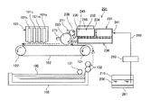
次に、本発明に係る泡状液体塗布装置及びその方法の第2実施形態について図3を参照して説明する。なお、図3は同装置の構成を示す模式的説明図である。 Next, a second embodiment of the foam liquid applicator and method according to the present invention will be described with reference to FIG. FIG. 3 is a schematic explanatory view showing the configuration of the apparatus.
この泡状液体塗布装置は、泡状態にすることが可能な液体1を収容する容器10と、この容器10から供給される液体1から所要の泡径より大きな泡径の泡状液体を生成する第1の泡生成手段である第1の泡状液体生成搬送手段31と、この第1の泡状液体生成搬送手段31で生成された泡状液体から更に所要泡径の泡状液体を生成する第2の泡生成手段である第2の泡状液体生成搬送手段32と、この第2の泡状液体生成搬送手段32で生成された泡状液体を被塗布部材に塗布する塗布手段である塗布ローラ33と、第1の泡状液体生成搬送手段31から第2の泡状液体生成搬送手段32への泡状液体の移動を通過/遮断する第1の開閉手段34と、第2の泡状液体生成搬送手段32から塗布ローラ33への泡状液体の移動を通過/遮断する第2の開閉手段35と、第1の泡状液体生成搬送手段31で生成された余分な泡状液体を回収するとともに、第2の泡状液体生成搬送手段32で生成されて塗布ローラ33に送り込まれなかった余分な泡状液体を回収して第1の泡状液体生成手段31側に循環させる回収手段及び循環手段を兼ねる回収循環手段36とを備えている。
The foam liquid application device generates a foam liquid having a foam diameter larger than a required foam diameter from the
第1の泡状液体生成搬送手段31は、前記第1実施形態の泡状液体生成搬送手段11と同様に、容器10から泡状液体になり得る液体1を網目状の取入口41から供給され、所要の泡径よりも大きな泡径の泡状液体を生成する。この泡状液体生成搬送手段11内には、前述した図2で説明した攪拌搬送部材22と同様な構成の、スクリュー状の撹拌羽42aを有する撹拌搬送部材42を単数又は複数備え、この攪拌搬送部材42を回転させることで、泡状液体を撹拌して、気体を巻込ませつつせん断力を加えて、供給されたときよりも泡径を小さくした泡状液体とし、第2の泡状液体生成搬送手段32側に向かって搬送を行い、更に網目状の部材で形成されている供給口43で更に泡径を細かくした泡状液体を生成する。
The first foam liquid generating / conveying
第2の泡状液体生成搬送手段32は、第1の泡状液体生成搬送手段31から送られてくる泡状液体から所要の泡径の泡状液体を生成する。この第2の泡状液体生成搬送手段32内には、前述した図2で説明した攪拌搬送部材22と同様な構成の、スクリュー状の撹拌羽44aを有する撹拌搬送部材44を単数又は複数備え、この攪拌搬送部材44を回転させることで、泡状液体を撹拌して、気体を巻込ませつつせん断力を加え、所要の泡径の泡状液体2を生成しながら塗布口45から塗布ローラ33に供給する。
The second foam liquid generating and conveying
塗布ローラ33は、第2の泡状液体生成搬送手段32の塗布口45から供給される泡状液体2が周面に転移されて、矢示方向への回転によって泡状液体2を移動させながら図示しない被塗布部材上に泡状液体2を塗布する。なお、塗布ローラ33に直接泡状液体を転移させる代わりに、塗布ローラ33と塗布口45との間に1又は複数の中間転移ローラを配置し、中間転移ローラに塗布口45から泡状液体を転移させ、更に中間転移ローラを介して塗布ローラ33に泡状液体を転移させる構成とすることもできる。
The
第1の開閉手段34は、第1の泡状液体生成搬送手段31の供給口43を開閉するように例えば矢示方向に昇降可能に配置され、第1の泡状液体生成搬送手段31で生成された泡状液体と第2の泡状液体生成搬送手段32で生成された泡状液体とが混合することを防止している。
The first opening / closing means 34 is disposed so as to be movable up and down, for example, in the direction of the arrow so as to open and close the supply port 43 of the first foamy liquid generation / conveyance means 31, and is generated by the first foamy liquid generation / conveyance means 31. This prevents the foamed liquid and the foamed liquid generated by the second foamed liquid generating and conveying
第2の開閉手段35は、第2の泡状液体生成搬送手段32の塗布口45を開閉するように例えば矢示方向に昇降可能に配置され、塗布ローラ33へ泡状液体を塗布する(供給する)ときのみ上昇して塗布口45を開口する。
The second opening / closing means 35 is arranged so as to be movable up and down, for example, in the direction of the arrow so as to open and close the
なお、第1の開閉手段34は第1の泡状液体生成搬送手段31又は第2の泡状液体生成搬送手段32の一部として構成することもでき、また、第2の開閉手段35は第2の泡状液体生成搬送手段32の一部として構成することもできる。
The first opening / closing means 34 can be configured as a part of the first foamy liquid generation / conveyance means 31 or the second foamy liquid generation / conveyance means 32, and the second opening / closing means 35 is the first opening / closing means 35. It can also be configured as a part of the two foam-like liquid generating and conveying
回収循環手段36は、第1の泡状生成搬送手段31の底面に形成した複数の穴46、第2の泡状生成搬送手段32の底面に形成した複数の穴47にそれぞれ連通する複数の穴48が天面に形成されるとともに、内部には、前述した図2で説明した攪拌搬送部材22と同様な構成の、スクリュー状の撹拌羽49aを有する撹拌搬送部材49を単数又は複数備えている。そして、この回収循環手段36は、塗布ローラ33に供給されなかった第2の泡状液体生成搬送手段32で生成された泡状液体2を複数の穴47及び48を介して受け入れることで回収し、撹拌搬送部材49によって第1の泡状液体生成搬送手段21側に移送する。さらに、第1の泡状液体生成搬送手段31の下側に移送された泡状液体は泡状液体が順次搬送されることで膨潤して、複数の穴48及び46を介して第1の泡状液体生成搬送手段31内に押し出され再度第1の泡状液体生成搬送手段31によって攪拌される。
The recovery circulation means 36 has a plurality of holes communicating with a plurality of
ここで、回収循環手段36の第2の泡状液体生成搬送手段32と接する面が傾斜していると、より循環がスムーズになる。また、第1の泡状液体生成搬送手段31側に溜まった泡状液体を第1の泡状液体生成搬送手段31側に押し上げる機構(手段)を備えることもできる。 Here, if the surface of the recovery / circulation means 36 that contacts the second foamy liquid generation / conveyance means 32 is inclined, the circulation becomes smoother. Further, a mechanism (means) for pushing up the foamy liquid accumulated on the first foamy liquid generation / conveyance means 31 side to the first foamy liquid production / conveyance means 31 side may be provided.
このように、泡状態にすることが可能な液体から所要の泡径より大きな泡径の泡状液体を生成し、更に所要泡径の泡状液体を生成して、この泡状液体を被塗布部材に塗布する構成とすることで、効率的に泡状態の液体を生成して塗布することができ、塗布の均一性を図れ、速乾性も得られる。 In this way, a foam liquid having a foam diameter larger than the required foam diameter is generated from the liquid that can be made into a foam state, and further a foam liquid having the required foam diameter is generated, and this foam liquid is applied. By adopting a configuration in which it is applied to the member, it is possible to efficiently generate and apply a liquid in a foam state, achieve uniformity of application, and obtain quick drying properties.
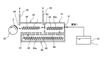
次に、本発明に係る画像形成装置の一実施形態について図4を参照して説明する。なお、図4は同画像形成装置の概略構成説明図である。 Next, an embodiment of an image forming apparatus according to the present invention will be described with reference to FIG. FIG. 4 is an explanatory diagram of a schematic configuration of the image forming apparatus.
この画像形成装置は、被記録媒体に用紙100に液滴を吐出して画像を形成する記録ヘッドユニット101と、用紙100を搬送する搬送ベルト102と、用紙100を収容する給紙トレイ103と、記録ヘッドユニット101よりも用紙搬送方向上流側で用紙100に泡状液体を塗布する本発明に係る泡状液体塗布装置201とを備えている。
The image forming apparatus includes a
記録ヘッドユニット101は、液滴を吐出する複数のノズルを用紙幅相当分の長さに配列したノズル列を有するライン型液体吐出ヘッドから構成され、それぞれイエロー(Y)、マゼンタ(M)、シアン(C)、ブラック(K)の各色のインク滴を記録ヘッド101y、101m、101c、101kを備えている。なお、シリアル型画像形成装置として記録ヘッドをキャリッジに搭載する構成ともできる。
The
搬送ベルト102は、無端状ベルトであり、搬送ローラ121とテンションローラ122との間に掛け渡されて周回するように構成している。この搬送ベルト102に対する用紙100の保持は、例えば静電吸着、空気の吸引による吸着などを行う構成とすることやその他の公知の搬送手段を用いることができる。
The
給紙トレイ103に収容された用紙100はピックアップローラ131で1枚ずつ分離給紙されて搬送ローラ対132によって搬送路を介して破線図示のように搬送ベルト102上に送り込まれて静電吸着される。
The
泡状液体塗布装置201は、泡状態になり得る液体200を収容する容器210と、この容器210から供給される液体200から所要の泡径より大きな泡径の泡状液体を生成する第1の泡生成手段である第1の泡状液体生成搬送手段231と、この第1の泡状液体生成搬送手段231で生成された泡状液体から更に所要泡径の泡状液体を生成する第2の泡生成手段である第2の泡状液体生成搬送手段232と、この第2の泡状液体生成搬送手段232で生成された泡状液体が塗布される中間転移ローラとしての第1の塗布ローラ238と、この第1の塗布ローラ238から泡状液体が供給されて塗布され、被塗布部材である用紙100に泡状液体を塗布する第2の塗布ローラ233と、第1の泡状液体生成搬送手段231から第2の泡状液体生成搬送手段232への泡状液体の移動を通過/遮断する第1の開閉手段234と、第2の泡状液体生成搬送手段232から第1の塗布ローラ238への泡状液体の移動を通過/遮断する第2の開閉手段235と、第1の泡状液体生成搬送手段231で生成された余分な泡状液体を回収するとともに、第2の泡状液体生成搬送手段232で生成されて第1の塗布ローラ238に送り込まれなかった余分な泡状液体を回収して第1の泡状液体生成手段231側に循環させる回収手段及び循環手段を兼ねる回収循環手段236とを備えている。
The foam
ここで、泡状態になり得る液体200は、用紙100の表面に塗布することで用紙100の表面を改質する改質材である。例えば、液体200は、予め用紙100(前述したように材質としていの紙に限定されない。)にムラなく塗布しておくことで、インクの水分を速やかに用紙100に浸透させると共に色成分を増粘させ、更には乾燥も早めることによって滲み(フェザリング、カラーブリード等)や裏抜けを防止し、生産性(単位時間当たりの画像出力枚数)をあげることを可能にする定着剤である。
Here, the liquid 200 that can be in a foam state is a modifying material that modifies the surface of the
この液体200は、組成的には、例えば界面活性剤(アニオン系、カチオン系、ノニオン系のいずれか、若しくはこれらを2種類以上混合させたもの)に対して、水分の浸透を促進するセルロース類(ヒドロキシプロピルセルロース等)とタルク微粉体の様な基剤を加えた溶液等を挙げることができる。更に微粒子を含有することもできる。 In terms of composition, the liquid 200 is, for example, a cellulose that promotes moisture permeation with respect to a surfactant (any one of anionic, cationic, nonionic, or a mixture of two or more thereof). Examples thereof include a solution obtained by adding a base such as hydroxypropylcellulose and talc fine powder. Furthermore, fine particles can be contained.
この泡状液体になり得る液体200を収容する容器210には、泡状液体になり得る液体200を周辺環境条件に左右されない温度に保つための保温手段261を備えている。この容器210に収容された液体200は、第1の泡状液体生成搬送手段231に対して経路262及び経路262中に配設したポンプ263によって供給される。
The
第1の泡状液体生成搬送手段231、第2の泡状液体生成手段232は、前述した第2実施形態の第1、第2の泡状液体生成搬送手段31、32と同様な構成であって、第1の泡状液体生成搬送手段231の取入口241から泡状態になりうる液体200を取り入れ、ここでは図示を省略する攪拌搬送部材を回転させ、攪拌と搬送を繰り返すことで所要の泡径の泡状液体を生成して第2の泡状液体生成搬送手段232の塗布口245から第1の塗布ローラ238に泡状液体を供給する。
The first foam liquid generating and conveying
第2の泡状液体生成搬送手段232には生成した泡状液体を周辺環境条件に左右されない温度に保つための第1の加熱手段265を備えている。この第1の加熱手段265は、電源オンと同時にオンさせて加熱を開始したり、消費電力を必要最小限に抑えるような所定のタイミングでオンさせて加熱を開始したりすることができる。
The second foam liquid generating and conveying
第1の開閉手段234は、第1の泡状液体生成搬送手段231と第2の泡状液体生成搬送手段232との間に介装され、第1の泡状液体生成搬送手段231から第2の泡状液体生成搬送手段23への泡状液体の移動を通過/遮断する手段であり、第1の泡状液体生成搬送手段31で生成された泡状液体と第2の泡状液体生成搬送手段232で生成された泡状液体とが混合することを防止している。
The first opening / closing means 234 is interposed between the first foam-like liquid generation / conveyance means 231 and the second foam-like liquid generation / conveyance means 232, and the first foam-like liquid generation / conveyance means 231 to the second Is a means for passing / blocking the movement of the foam-like liquid to the foam-like liquid producing / conveying
第2の開閉手段235は、第2の泡状液体生成搬送手段232から第1の塗布ローラ238との間に介装されて、第2の泡状液体生成搬送手段232から塗布手段への泡状液体の移動を通過/遮断する手段であり、第2の泡状液体生成搬送手段232の塗布口245を開閉することで第1の塗布ローラ238へ塗布する(供給する)の泡状液体の量を調整することができる。これにより、無駄なく泡状液体を塗布手段に転移(移送)することができる。
The second opening / closing means 235 is interposed between the second foam-like liquid generation / conveyance means 232 and the
この第2の開閉手段235としては、図5に示すように、上下に昇降することで第2の泡状液体生成搬送手段232の塗布口245を開閉するもの、図6に示すように、横方向(用紙の幅方向に相当する。)に移動することで第2の泡状液体生成搬送手段232の塗布口245を開閉するものなどを挙げることができる。
As the second opening / closing means 235, as shown in FIG. 5, the
この場合、図5に示す第2の開閉手段35の構成では、塗布ローラ238の周方向への塗布領域を調整することができ、これにより用紙100に対する搬送方向の塗布領域を制御することができる。また、図6に示す第2の開閉手段35の構成では、開閉によって塗付ローラ238の周方向への塗付領域を調整することができるとともに、塗布ローラ238の軸方向への塗布領域を調整することができ、これにより用紙100に対する幅方向(搬送方向と直交する方向)の塗布領域も制御することができる。
In this case, in the configuration of the second opening / closing means 35 shown in FIG. 5, the application region in the circumferential direction of the
回収循環手段236は、前述した第2実施形態と同様に構成され、第2の泡状液体生成搬送手段32で生成された泡状液体を受け入れて、図示を省略する撹拌搬送部材によって第1の泡状液体生成搬送手段21側に移送する。
The recovery circulating means 236 is configured in the same manner as in the second embodiment described above, receives the foamy liquid generated by the second foamy liquid generating and conveying
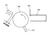
第1の塗布ローラ238は、矢示方向に回転することで第2の泡状液体生成搬送手段232から供給される泡状液体が周面に塗布され、第2の塗布ローラ233に対向する位置で泡状液体を第2の塗布ローラ233に転移させる。この第1の塗布ローラ238の周面に対向して第1の塗布ローラ238に塗布された泡状液体の膜厚を均一化する膜厚設定部材271を配置し、更に第2の塗布ローラ233に対する塗布後に第1の塗布ローラ238に残存付着している泡状液体を除去する第1の泡状液体除去手段272を配置している。
The
なお、膜厚設定部材271は、図7に示すように、矢示方向に移動可能に配置され、第1の塗布ローラ238との間の距離を制御することにより膜厚を任意に調整でき、例えば、画像形成装置の操作表示部から所定の操作を行うことで調整できるようにしている。これにより、泡状液体の塗布膜厚を任意の値に設定することができ、想定外の使用条件における対応が可能になる。
As shown in FIG. 7, the film
第2の塗布ローラ233は、矢示方向に回転することで第1の塗布ローラ238に対向する位置で泡状液体が周面に塗布されて、用紙30に均一な膜厚の泡状液体を塗布する。この第2の塗布ローラ233の周面に対向して塗布後の第2の塗布ローラ233に残存付着している泡状液体を除去する第2の泡状液体除去手段273を配置している。
The
このように、第1の塗布ローラ238、第2の塗布ローラ233に塗布されて不要となった泡状液体を除去する泡状液体除去手段を備えることで、次工程、次手段の印字領域外の泡状液体の塗布回避を確実にすることができるとともに、より安定した膜厚での泡状液体の塗布を実現することができる。
In this way, by providing the foam liquid removing means for removing the foam liquid that has become unnecessary after being applied to the
なお、第2の塗布ローラ233には、消費電力を最小限に抑えつつ、用紙100への泡状液体塗布後に周面に残存する泡状液体の乾燥、泡状液体塗布直後の用紙100上の泡状液体の乾燥を早く行うために、所定のタイミングで制御できる第2の加熱手段を備えることができる。
In addition, the
また、搬送ベルト102を周回移動させる搬送ローラ121及び従動ローラ122の少なくともいずれか一方に搬送ベルト102を介して用紙100や塗布された泡状液体を加熱する第2の加熱手段を備えることができる。この第3の加熱手段は、消費電力を最小限に抑えつつ、用紙100に泡状液体を塗布後膜厚設定手段に残った泡状液体の乾燥、泡状液体塗布直後の用紙100上の泡状液体の乾燥を早く行うことができるとともに、用紙100を温めることで印字後の液滴の乾燥を早めるような最適のタイミングで制御される。
Further, at least one of the
次に、この画像形成装置に制御部の概要について図8に示すブロック図を参照して説明する。 Next, an outline of a control unit in this image forming apparatus will be described with reference to a block diagram shown in FIG.
この制御部は、本画像形成装置のシステム制御を行うCPU801と、CPU801が実行するプログラムなどの情報を格納するROM802と、ワーキングエリアとして使用するRAM803と、オペレータが各種設定等を行うため操作表示部804と、紙サイズ検知やジャム検知等を行う各種センサ805と、各種モータ等806と、各種センサ805及び各種モータ等806への出力制御信号を行うI/O807と、画像読取り装置(スキャナ)808を制御する読取り制御部809と、プロッタ部(印字機構部)810を制御する印字制御部811と、電話回線とのI/F制御を行う網制御装置812の制御も含めて、各種ファクシミリ通信制御を行う通信制御部813と、泡状液体塗布装置201の制御を行う泡状液体塗布制御部814等を備えている。
The control unit includes a
ここで、各種センサ805には、環境条件を検出する温度/湿度検知手段、泡状液体になり得る液体200が容器210内にあるか否か検知する液体エンド検知手段を含む。
Here, the
次に、このように構成した画像形成装置における印刷処理について図9ないし図12のフロー図をも参照して説明する。 Next, the printing process in the image forming apparatus configured as described above will be described with reference to the flowcharts of FIGS.
先ず、図9を参照して、画像出力要求を受信したならば、用紙100が予め定められた専用用紙か否かを判別して、専用用紙であるときには、第2の塗布ローラ233の回転を開始し、搬送ローラ121を回転駆動して搬送ベルト102を周回移動させ、所定のタイミングで給紙トレイ103から用紙100の給紙を開始し、搬送ベルト102によって用紙100を搬送して記録ヘッドユニット101による画像形成位置に搬送し、記録ヘッドユニット101から液滴を吐出させて用紙100上に所用の画像を形成し、所要枚数の印刷を完了したときに、搬送ローラ対132などの給紙部の停止、第2の塗布ローラ233の停止、搬送ローラ121の停止などを行って、この処理を抜ける。なお、専用用紙とは表面にコート層などが形成されたインクジェット記録装置専用用紙を意味している。
First, referring to FIG. 9, when an image output request is received, it is determined whether or not the
これに対して、用紙100が専用用紙でないときには、図10に示すように、ポンプ263を駆動して容器210から液体200を泡状液体塗布装置201の第1の泡状液体生成搬送手段231に供給し、前述したように、第1、第2の泡状液体生成搬送手段231、232、回収循環手段236の攪拌搬送部材を駆動し、第1の開閉手段234を開いて、所定泡径の泡状液体の生成を開始する。
On the other hand, when the
その後、第1の加熱手段265の設定がオンか否かを判別して、第1の加熱手段265の設定がオンのときには第1の加熱手段265に対して所定の制御を行うことによって第2の泡状液体生成搬送手段232の温度を所定の値に制御する。
Thereafter, it is determined whether or not the setting of the first heating means 265 is on, and when the setting of the first heating means 265 is on, predetermined control is performed on the first heating means 265 to perform the second control. The temperature of the foam liquid generating and conveying
ここで、電源オンすると同時に泡状液体生成手段内の泡状液体を加熱する第1の加熱手段をオンすることで、画像形成装置を使用中に泡状液体生成手段内の泡状液体を周囲環境の影響を受けない安定した品質で塗布手段に送り込みたい場合に、加熱手段をユーザーがオンする手間を省くことができる。また、泡状液体生成手段内の泡状液体を加熱する加熱手段を所定のタイミングでオンする構成とすることで、消費電力に無駄がなく、かつ周囲温度の影響を受けない安定した品質の泡状液体を塗布手段に送り込むことができる。 Here, by turning on the first heating means for heating the foam liquid in the foam liquid generation means at the same time when the power is turned on, the foam liquid in the foam liquid generation means is surrounded while the image forming apparatus is in use. When it is desired to feed the coating means with a stable quality that is not affected by the environment, it is possible to save the user from turning on the heating means. In addition, by adopting a configuration in which the heating means for heating the foam liquid in the foam liquid generating means is turned on at a predetermined timing, there is no waste in power consumption, and bubbles of stable quality that are not affected by the ambient temperature. Liquid can be fed into the application means.
次いで、用紙100に対して泡状液体を均一に塗布できる所定のタイミングで、第2の開閉手段235を開くと同時に第1の塗布ローラ238、第2の塗布ローラ233、更には搬送ベルト102を駆動し、第2の泡状液体生成搬送手段232から第1の塗布ローラ238へ泡状液体を塗布し、第1の塗布ローラ238に塗布された泡状液体の膜厚を膜厚設定部材271で膜厚調整し、膜厚調整された泡状液体を第1の塗布ローラ238から第2の塗布ローラ233に塗布させる。
Next, the second opening / closing means 235 is opened and the
そして、第2の塗布ローラ238に具備されている図示しない第2の加熱手段の設定がオンか否かを判別し、第2の加熱手段の設定がオンのときには、第2の加熱手段に対し、第2の塗布ローラ238が図示しない温度/湿度検知手段に応じた温度に達するように制御する。
Then, it is determined whether or not the setting of the second heating means (not shown) provided in the
さらに、図示しない第3の加熱手段の設定がオンになっているか否かを判別し、第3の加熱手段の設定がオンのときには、第3の加熱手段に対し、搬送ベルト102が温度/湿度検知手段に応じた温度になる制御する。
Further, it is determined whether or not the setting of the third heating means (not shown) is turned on. When the setting of the third heating means is turned on, the
このように、第2の加熱手段、第3の加熱手段を制御することにより、消費電力を最小限に抑えつつ、用紙100への塗布後に第2の塗布ローラ233に残った泡状液体の乾燥、泡状液体塗布直後の用紙100上の泡状液体の乾燥を促進させ、更には用紙100を温めることで印字後の液滴の乾燥を促進することができる。つまり、膜厚設定手段に具備されている第2の加熱手段を所定のタイミングで制御することで、消費電力を最小限に抑えつつ、被記録媒体塗布後に膜厚設定手段に残った泡状液体の乾燥、泡状液体塗布直後の被記録媒体上の泡状液体の乾燥を早く行うことができる。また、被記録媒体を搬送する搬送手段に具備されている第3の加熱手段を所定のタイミングで制御することで、消費電力を最小限に抑えつつ、被記録媒体塗布後に膜厚設定手段に残った泡状液体の乾燥、泡状液体塗布直後の被記録媒体上の泡状液体の乾燥を早く行うことができるとともに、被記録媒体を温めるので、より印字後の液滴の乾燥を早めることができる。さらに、装置の環境条件、すなわち、温度、湿度情報に基づいた加熱手段の制御を行うことで、より周囲環境に適した乾燥時間短縮と使用消費電力の最小限化を実現できる。
Thus, by controlling the second heating means and the third heating means, the foamed liquid remaining on the
その後、図11に示すように、所定のタイミングで給紙を行って搬送ベルト102で搬送される用紙100に対し、第2の塗布ローラ233によって泡状液体の塗布を開始する。このとき、泡状液体の塗布領域を用紙サイズに応じた領域として泡状液体を塗布する用紙サイズ領域塗布モードであるか否かを判別し、用紙サイズ領域塗布モードであれば、用紙100のサイズ領域分第1の塗布ローラ238に泡状液体が塗布されるように第2の開閉手段235を開閉する。
After that, as shown in FIG. 11, the application of the foam liquid is started by the
また、用紙サイズ領域塗布モードでなければ、泡状液体の塗布領域を印字データ領域に応じた領域として泡状液体を塗布する印字データ領域塗布モードであるか否かを判別し、印字データ領域塗布モードであるときには、印字データ領域相当に領域分のみ第1の塗布ローラ238に泡状液体が塗布されるように第2の開閉手段235を開閉する。その後、第1、第2の開閉手段234、235を閉じる。
If it is not the paper size area application mode, it is determined whether or not it is the print data area application mode in which the foam liquid is applied with the foam liquid application area as an area corresponding to the print data area, and the print data area application mode is determined. In the mode, the second opening / closing means 235 is opened and closed so that the foam liquid is applied to the
このように、第1、第2の開閉手段234、235を、画像出力要求を受けて所定のタイミングで動作させるので、特にきめ細かい泡状液体を無駄なく効率的に、周囲温度の影響を受けない安定した品質で塗布手段に送り込むことができる。 As described above, since the first and second opening / closing means 234 and 235 are operated at a predetermined timing in response to the image output request, the fine foam liquid is not affected by the ambient temperature efficiently without waste. It can be sent to the coating means with stable quality.
このようにして、用紙100に対して予め設定された領域に泡状液体を塗布することができる。このように、被記録媒体に泡状液体を塗布する領域を制御することによって泡状液体を塗布して汚すことなく、泡状液体の浪費を防止することができる。また、特に指定された被記録媒体のサイズに応じた領域に対してのみ泡状液体を被記録媒体に塗布するので、オペレータが用紙サイズに応じて泡状液体の塗布領域を指定するというような余分な操作をすることなく、滲み、裏写り、濃度ムラ等のない良質な画像を出力することができる。また、印字データに基づいた領域のみに泡状液体を塗布することによって更に無駄なく泡状液体を塗布して定着剤の節約を実現できる。
In this way, it is possible to apply the foamy liquid to a region set in advance on the
そして、所要の領域に泡状液体が塗布された用紙100は搬送ベルト102で更に搬送されて記録ヘッドユニット101から液滴が吐出されて所要の画像が形成され、排紙される。
Then, the
印字すべき用紙100が所定枚数(終了枚数)に達するまで、泡状液体の塗布動作を行い、終了枚数に達したならば、図12に示すように、液体供給ポンプ263、第1の泡状液体生成搬送手段231、第2の泡状液体生成搬送手段232、第1の加熱手段265、給紙部の停止、第1の開閉手段234、と第2の開閉手段235の閉結を行う。
The foam liquid application operation is performed until the number of
その後、所定時間の経過、すなわち、第1の塗布ローラ238、第2の塗布ローラ236に対して第1の泡状液体除去手段272、第2の泡状液体除去手段273による泡状液体除去が充分行われるための時間が経過した後、第1の塗布ローラ238、第2の塗布ローラ233、第2の加熱手段、第3の加熱手段、搬送ベルト102を停止し、泡状液体塗布工程を終了する。
Thereafter, the elapse of a predetermined time, that is, the foam liquid removal by the first foam liquid removal means 272 and the second foam liquid removal means 273 is performed on the
このように、用紙100の表面に泡状液体を塗布することによって、塗布の均一性を図れ、速乾性が向上し、滲み、裏写り、濃度ムラ等のない良質な画像を出力することができる。
In this way, by applying the foam liquid to the surface of the
次に、液体の保温制御について図13及び図14のフロー図を参照して説明する。 Next, the liquid heat retention control will be described with reference to the flow charts of FIGS. 13 and 14.
先ず、図13を参照して、この画像形成装置の電源がオンされると、容器210に液体200が入っているか否かを図示しない液体エンド検知手段の検出結果に基づいて判別し、液体200が容器210に入っていないときには操作表示部804にエラー表示する。また、液体200が容器210に入っているときには、保温手段オンタイミング設定をチェックし、保温手段オンタイミング設定が常時オン設定か否かを判別して、常時オン設定であるときには保温手段261をオン状態にする。そして、電源スイッチがオフされても、保温手段261をオフしないでオン状態を維持する。
First, referring to FIG. 13, when the power of the image forming apparatus is turned on, it is determined whether or not the liquid 200 is contained in the
これに対し、保温手段タイミング設定が常時オンでなければ、図14に示すように、保温手段タイミング設定が電源オン時になっているか否かを判別し、電源オン時の設定であるときには保温手段261をオンし、電源スイッチがオフされたら保温手段261もオフ状態にする。このように、電源オンすると同時に保温手段261をオンすることで、画像形成装置を使用中に泡状液体になり得る液体200を周囲環境の影響を受けない、安定した品質で泡状液体生成手段に送り込む込むことができ、保温手段をユーザーがオンする手間を省くことができる。 On the other hand, if the heat retaining means timing setting is not always on, as shown in FIG. 14, it is determined whether or not the heat retaining means timing setting is set when the power is turned on. When the power switch is turned off, the heat retaining means 261 is also turned off. Thus, by turning on the heat retaining means 261 at the same time as turning on the power, the liquid 200 that can become a foamy liquid during use of the image forming apparatus is not affected by the surrounding environment, and the foamed liquid generating means has a stable quality. The user can save the trouble of turning on the heat retaining means.
また、保温手段タイミング設定が電源オン時でもなければ、保温手段タイミング設定が電源オフ時になっているか否かを判別し、電源オフ時であるときには、保温手段261をオフのままとし、電源スイッチがオフされたときに保温手段261をオン状態にする。このように、電源オフすると同時に保温手段261をオンする構成とすることで、特に電源オフ時に保温手段261をオンしておき、使用中は消費電力を極力抑えるために保温手段261をオフしておきたい寒冷地での使用に適しており、保温手段261をユーザーがオンする手間を省くことができる。 Further, if the heat retention means timing setting is not when the power is on, it is determined whether or not the heat retention means timing setting is when the power is off. If the power is off, the heat retention means 261 is kept off and the power switch is turned off. When it is turned off, the heat retaining means 261 is turned on. As described above, the heat retaining means 261 is turned on at the same time as the power is turned off, so that the heat retaining means 261 is turned on particularly when the power is turned off, and the heat retaining means 261 is turned off during use to suppress power consumption as much as possible. It is suitable for use in a cold region, and it is possible to save the user from turning on the heat retaining means 261.
なお、電源オン中は定期的に容器210に液体200が入っているか否かを液体エンド検出手段の検出結果をチェックして判別し、エンド検知時は操作表示部804へのエラー表示、エンド非検知時はそのままの状態を維持する。
During power-on, it is periodically determined whether or not the liquid 200 is contained in the
また、このように、電源オンすると同時に泡状液体になり得る液体の容器を保温する保温手段をオンするか、電源オフすると同時に保温手段をオンするか、常時保温手段をオンしているかを選択できるようにすることで、あらゆる環境の下で保温手段をオペレータがオンする手間を省くことができる。 In addition, in this way, select whether to turn on the heat retaining means that keeps the container of the liquid that can become a foamy liquid at the same time when the power is turned on, whether to turn on the heat retaining means at the same time that the power is turned off, or whether the heat retaining means is always on By making it possible, it is possible to save the operator from turning on the heat retaining means in any environment.
次に、膜厚設定処理について図15のフロー図を参照して説明する。 Next, the film thickness setting process will be described with reference to the flowchart of FIG.
操作表示部804で所定の操作が行われることにより、泡状液体膜厚設定モードに入った後、設定したい膜厚入力を促し、オペレータが膜厚を入力しらた、第1の塗布ローラ238と膜厚設定部材271の距離(図7参照)を入力された値に変更する。
When a predetermined operation is performed on the
なお、これ以外にも、各加熱手段の設定、保温手段の設定や機能のオン/オフ等、操作表示部804から所定の操作を行うことができる。操作表示部804から各種タイミング、膜厚等のパラメータ、機能のオン/オフ設定を、所定の操作を行うことで任意に変更できるようにすることで、想定外の使用条件においても最適な画像を最低限の消費電力で出力できるように調整できる。
In addition to this, it is possible to perform a predetermined operation from the
このように、泡状液体塗布手段は、泡状態にすることが可能な液体を収容する容器と、この容器から供給される液体から所要の泡径より大きな泡径の泡状液体を生成する第1の泡生成手段と、この第1の泡生成手段で生成された泡状液体から更に所要泡径の泡状液体を生成する第2の泡生成手段と、この第2の泡生成手段で生成された泡状液体を被記録媒体に塗布する塗布手段とを備えていることで、きめ細かい泡状液体を効率的に生成して被記録媒体に塗布することができる。 In this way, the foam liquid application means generates a foam liquid having a bubble diameter larger than a required bubble diameter from the container that stores the liquid that can be made into a foam state and the liquid supplied from the container. 1 foam generating means, a second foam generating means for further generating a foam liquid having a required bubble diameter from the foam liquid generated by the first foam generating means, and the second foam generating means. By providing application means for applying the foamed liquid to the recording medium, a fine foamy liquid can be efficiently generated and applied to the recording medium.
この場合、塗布手段に送り込む必要のない泡状液体を回収する回収手段を備えていることで、常に新しく、きめ細かな泡状液体を塗布できる。更に、回収した泡状液体を第1の泡生成手段に循環させる構成とすることで、無駄なく泡状液体を利用することができる。また、第1の泡生成手段と第2の泡生成手段との間に泡状液体の移動を通過/遮断する開閉手段を備えている構成とすることで、泡径の異なる泡状液体が混合することを防止できる。また、第2の泡生成手段と塗布手段との間に泡状液体の移動を通過/遮断する手段を備えている構成とすることで、無駄なく塗布手段に泡状液体を転移することができる。更に、泡状液体の移動を通過/遮断する手段は泡状液体が通過する領域を変更可能である構成とすることで、より一層無駄なく泡状液体を塗布することができる。 In this case, a new and fine foam liquid can always be applied by providing the recovery means for recovering the foam liquid that does not need to be sent to the application means. Furthermore, by using a configuration in which the recovered foam liquid is circulated through the first foam generating means, the foam liquid can be used without waste. In addition, by providing an opening / closing means for passing / blocking the movement of the foamy liquid between the first foam generating means and the second foam generating means, the foamy liquids having different foam diameters are mixed. Can be prevented. Further, by providing a means for passing / blocking the movement of the foam liquid between the second foam generating means and the application means, the foam liquid can be transferred to the application means without waste. . Further, the means for passing / blocking the movement of the foam liquid can change the region through which the foam liquid passes, so that the foam liquid can be applied more efficiently.
また、上記実施形態では泡状液体塗布装置が画像形成前の用紙に対して泡状液体を塗布する構成で説明しているが、記録ヘッドユニット101の下流側に泡状液体塗布装置201を配置し、画像形成が行われた用紙上に泡状液体を塗布する構成とすることもできる。
In the above embodiment, the foam liquid application device is described as applying the foam liquid to the paper before image formation. However, the foam
100…用紙
101…記録ヘッドユニット
102…搬送ベルト
103…給紙トレイ
200…泡状態になる液体
201…泡状液体塗布装置
231…第1の泡状液体生成搬送手段
232…第2の泡状液体生成搬送手段
233…第2の塗布ローラ
234…第1の開閉手段
235…第2の開閉手段
236…回収循環手段
238…第1の塗布ローラ
271…膜厚設定部材
272…第1の泡状液体除去手段
273…第1の泡状液体除去手段
261…保温手段
265…第1の加熱手段
DESCRIPTION OF
Claims (11)
前記被記録媒体の表面に塗布することで前記被記録媒体の表面を改質する液体を泡状態にする泡生成手段と、
所定の隙間を通過させることにより、前記泡状態の液体の膜厚を設定する膜厚設定手段と、
前記被記録媒体に対して膜厚が設定された前記泡状態の液体を塗布する泡状液体塗布手段と、を備えている
ことを特徴とする画像形成装置。 In an image forming apparatus that includes a recording head for discharging droplets and forms an image on a recording medium.
A bubble generating means for applying a liquid on the surface of the recording medium to change the surface of the recording medium into a bubble state;
A film thickness setting means for setting the film thickness of the liquid in the bubble state by passing a predetermined gap;
An image forming apparatus comprising: a foam liquid applying unit that applies the foamed liquid having a film thickness set on the recording medium.
泡状態にすることが可能な液体を収容する容器と、
この容器から供給される前記液体から被記録媒体に塗布される泡径より大きな泡径の泡状液体を生成する第1の泡生成手段と、
この第1の泡生成手段で生成された泡状液体から更に被記録媒体に塗布される泡径の泡状液体を生成する第2の泡生成手段と、を備え、
前記泡状液体塗布手段は、前記第2の泡生成手段で生成された泡状液体を前記被記録媒体に塗布する
ことを特徴とする請求項1又は2に記載の画像形成装置。 The foam generating means includes
A container containing a liquid that can be made into a foam state;
A first bubble generating means for generating a foam liquid having a larger bubble diameter than that applied to the recording medium from the liquid supplied from the container;
A second foam generating means for generating a foam liquid having a foam diameter to be applied to the recording medium from the foam liquid generated by the first foam generating means ,
It said foamed liquid coating unit, the image forming according to the foamed liquid produced by the second bubble generating means to claim 1 or 2, characterized in <br/> that you applied to the recording medium apparatus.
Priority Applications (1)
| Application Number | Priority Date | Filing Date | Title |
|---|---|---|---|
| JP2012184625A JP5288034B2 (en) | 2012-08-23 | 2012-08-23 | Image forming apparatus |
Applications Claiming Priority (1)
| Application Number | Priority Date | Filing Date | Title |
|---|---|---|---|
| JP2012184625A JP5288034B2 (en) | 2012-08-23 | 2012-08-23 | Image forming apparatus |
Related Parent Applications (1)
| Application Number | Title | Priority Date | Filing Date |
|---|---|---|---|
| JP2007178698A Division JP5075300B2 (en) | 2007-07-06 | 2007-07-06 | Image forming apparatus |
Publications (2)
| Publication Number | Publication Date |
|---|---|
| JP2012250540A JP2012250540A (en) | 2012-12-20 |
| JP5288034B2 true JP5288034B2 (en) | 2013-09-11 |
Family
ID=47523792
Family Applications (1)
| Application Number | Title | Priority Date | Filing Date |
|---|---|---|---|
| JP2012184625A Expired - Fee Related JP5288034B2 (en) | 2012-08-23 | 2012-08-23 | Image forming apparatus |
Country Status (1)
| Country | Link |
|---|---|
| JP (1) | JP5288034B2 (en) |
Families Citing this family (1)
| Publication number | Priority date | Publication date | Assignee | Title |
|---|---|---|---|---|
| JP2021085610A (en) * | 2019-11-28 | 2021-06-03 | 株式会社リコー | Liquid ejection device |
Family Cites Families (1)
| Publication number | Priority date | Publication date | Assignee | Title |
|---|---|---|---|---|
| JP5075300B2 (en) * | 2007-07-06 | 2012-11-21 | 株式会社リコー | Image forming apparatus |
-
2012
- 2012-08-23 JP JP2012184625A patent/JP5288034B2/en not_active Expired - Fee Related
Also Published As
| Publication number | Publication date |
|---|---|
| JP2012250540A (en) | 2012-12-20 |
Similar Documents
| Publication | Publication Date | Title |
|---|---|---|
| JP5075300B2 (en) | Image forming apparatus | |
| JP5347527B2 (en) | Image forming device, foam coating device | |
| US20090151625A1 (en) | Image forming apparatus and foam application device | |
| JP5320912B2 (en) | Image forming apparatus, apparatus for applying foam to coated member | |
| JP5321026B2 (en) | Image forming device, foam coating device | |
| JP2011189588A (en) | Image forming apparatus | |
| JP5476767B2 (en) | Image forming device, foam coating device | |
| JP5288034B2 (en) | Image forming apparatus | |
| JP5803113B2 (en) | Image forming apparatus and processing liquid coating apparatus | |
| JP5181945B2 (en) | Image forming device, foam coating device | |
| JP5182083B2 (en) | Image forming apparatus | |
| JP5321027B2 (en) | Image forming device, foam coating device | |
| JP5332817B2 (en) | Image forming device, foam coating device | |
| JP5581821B2 (en) | Image forming apparatus and processing liquid coating apparatus | |
| JP5470971B2 (en) | Image forming device, foam coating device | |
| JP5375185B2 (en) | Image forming device, foam coating device | |
| JP5272854B2 (en) | Image forming device, foam coating device | |
| JP5257076B2 (en) | Image forming apparatus | |
| JP2009061734A (en) | Image formation device and device for applying foamed liquid to application objective member |
Legal Events
| Date | Code | Title | Description |
|---|---|---|---|
| A131 | Notification of reasons for refusal |
Free format text: JAPANESE INTERMEDIATE CODE: A131 Effective date: 20121218 |
|
| A521 | Written amendment |
Free format text: JAPANESE INTERMEDIATE CODE: A523 Effective date: 20130125 |
|
| TRDD | Decision of grant or rejection written | ||
| A01 | Written decision to grant a patent or to grant a registration (utility model) |
Free format text: JAPANESE INTERMEDIATE CODE: A01 Effective date: 20130507 |
|
| A61 | First payment of annual fees (during grant procedure) |
Free format text: JAPANESE INTERMEDIATE CODE: A61 Effective date: 20130520 |
|
| R151 | Written notification of patent or utility model registration |
Ref document number: 5288034 Country of ref document: JP Free format text: JAPANESE INTERMEDIATE CODE: R151 |
|
| LAPS | Cancellation because of no payment of annual fees |