JP2010082631A - Laser processing apparatus - Google Patents
Laser processing apparatus Download PDFInfo
- Publication number
- JP2010082631A JP2010082631A JP2008251342A JP2008251342A JP2010082631A JP 2010082631 A JP2010082631 A JP 2010082631A JP 2008251342 A JP2008251342 A JP 2008251342A JP 2008251342 A JP2008251342 A JP 2008251342A JP 2010082631 A JP2010082631 A JP 2010082631A
- Authority
- JP
- Japan
- Prior art keywords
- laser
- workpiece
- positioning
- positioning optical
- pair
- Prior art date
- Legal status (The legal status is an assumption and is not a legal conclusion. Google has not performed a legal analysis and makes no representation as to the accuracy of the status listed.)
- Granted
Links
Images

Landscapes
- Laser Beam Processing (AREA)
Abstract
Description
本発明は、レーザ発振器から出力されたレーザを位置決めする一対の位置決め光学系を備え、ワークの表面側と裏面側を一度に加工するようにしたレーザ加工装置に関する。 The present invention relates to a laser processing apparatus including a pair of positioning optical systems for positioning a laser output from a laser oscillator, and processing a front surface side and a back surface side of a workpiece at a time.
例えば、配線パターンが表面側と裏面側に形成されたいわゆる両面プリント基板を加工するため、レーザ発振器とレーザ発振器から出力されたレーザをワーク上の所望の位置に位置決めする一対の位置決め光学系を備え、ワークである両面プリント基板を挟むようにして2つの位置決め光学系を対向させて配置させておき、ワークの表面側と裏面側を一度に加工するようにしたレーザ加工装置が知られている(特許文献1参照)。 For example, in order to process a so-called double-sided printed circuit board with wiring patterns formed on the front and back sides, a laser oscillator and a pair of positioning optical systems that position the laser output from the laser oscillator at a desired position on the workpiece are provided. In addition, there is known a laser processing apparatus in which two positioning optical systems are arranged facing each other so as to sandwich a double-sided printed circuit board that is a workpiece, and the front surface side and the back surface side of the workpiece are processed at once (Patent Document). 1).
この技術によれば、ワーク裏面の加工を行う際にワークを裏返しにする必要がなく、また、ワークの位置決めも一度行えばよいので、段取り時間を短縮でき、加工能率を向上させることができるものである。 According to this technology, it is not necessary to turn the workpiece upside down when machining the back side of the workpiece, and it is only necessary to position the workpiece once, so the setup time can be shortened and the machining efficiency can be improved. It is.
しかしながら、両面プリント基板等のワークをレーザで加工する場合、止まり穴だけでなく、貫通孔を加工する場合がある。上記従来技術の場合、ワークの表面側を加工する位置決め光学系と裏面側を加工する位置決め光学系とが同軸上に対向して配置されているため、貫通孔を加工すると、ワークを貫通した一方のレーザが他方の位置決め光学系を介して他方のレーザ発振器に戻り、他方のレーザ発振器を損傷させる場合があった。 However, when a workpiece such as a double-sided printed circuit board is processed with a laser, not only a blind hole but also a through hole may be processed. In the case of the above prior art, the positioning optical system for processing the front surface side of the workpiece and the positioning optical system for processing the back surface side are disposed so as to be coaxially opposed to each other. This laser may return to the other laser oscillator via the other positioning optical system and damage the other laser oscillator.
本発明の目的は、上記課題を解決し、ワークを貫通したレーザがレーザ発振器を損傷させることがなく、ランニングコストを低減することができるレーザ加工装置を提供することにある。 An object of the present invention is to solve the above-mentioned problems, and to provide a laser processing apparatus capable of reducing running costs without causing a laser penetrating a workpiece to damage a laser oscillator.
本発明は(例えば、図1及び図2参照)、レーザ発振器(1)から出力されたレーザを板状のワーク(30)上の所定の位置に位置決めする一対の位置決め光学系(20a,20b)を備え、前記一対の位置決め光学系(20a,20b)を対向させて配置し、前記一対の位置決め光学系の一方(20a)により前記ワーク(30)の表面側を、前記一対の位置決め光学系の他方(20b)により前記ワーク(30)の裏面側を、それぞれ加工するようにしたレーザ加工装置において、
前記各位置決め光学系(20a,20b)は、前記ワーク(30)の面に沿う第1の軸方向(X軸方向)及び前記第1の軸方向と直交し、前記ワーク(30)の面に沿う第2の軸方向(Y軸方向)にレーザを走査するスキャナ部(7a,7b)と、前記スキャナ部(7a,7b)を通過したレーザを集光して前記ワーク(30)に照射するfθレンズ(8a,8b)と、を有し、
前記各位置決め光学系(20a,20b)の前記fθレンズ(8a,8b)から照射されるレーザの位置決め領域(12a,12b)が前記fθレンズ(8a,8b)の主軸方向に重ならないように、前記各fθレンズ同士(8a,8b)を前記主軸方向と直交する方向にずらして配置した、
ことを特徴とするレーザ加工装置(100)にある。
In the present invention (see, for example, FIGS. 1 and 2), a pair of positioning optical systems (20a, 20b) for positioning a laser output from a laser oscillator (1) at a predetermined position on a plate-like workpiece (30). The pair of positioning optical systems (20a, 20b) are arranged to face each other, and the surface side of the workpiece (30) is placed on the surface side of the workpiece (30) by one of the pair of positioning optical systems (20a). In the laser processing apparatus in which the back side of the workpiece (30) is respectively processed by the other (20b),
Each positioning optical system (20a, 20b) is orthogonal to the first axial direction (X-axis direction) and the first axial direction along the surface of the workpiece (30), and is on the surface of the workpiece (30). The scanner unit (7a, 7b) that scans the laser in the second axial direction (Y-axis direction) along the beam and the laser beam that has passed through the scanner unit (7a, 7b) are condensed and irradiated onto the workpiece (30). fθ lenses (8a, 8b),
The positioning regions (12a, 12b) of the laser irradiated from the fθ lenses (8a, 8b) of the positioning optical systems (20a, 20b) do not overlap in the main axis direction of the fθ lenses (8a, 8b). The fθ lenses (8a, 8b) are shifted in the direction perpendicular to the principal axis direction.
There exists in the laser processing apparatus (100) characterized by the above-mentioned.
また、上記レーザ加工装置(100)において、前記ワーク(30)の表面と裏面に対向させる一対の遮蔽板(13a,13b)を備え、
一方の前記遮蔽板(13a)を、他方の前記位置決め領域(12b)と対向するように前記一対の位置決め光学系の一方(20a)側に配置し、他方の前記位置決め光学系(20b)より照射されて前記ワーク(30)を貫通したレーザを遮蔽すると共に、
他方の前記遮蔽板(13b)を、一方の前記位置決め領域(12a)と対向するように前記一対の位置決め光学系の他方(20b)側に配置し、一方の前記位置決め光学系(20a)より照射されて前記ワーク(30)を貫通したレーザを遮蔽する、
ことを特徴とするものである。
The laser processing apparatus (100) further includes a pair of shielding plates (13a, 13b) opposed to the front surface and the back surface of the workpiece (30).
One shielding plate (13a) is disposed on one (20a) side of the pair of positioning optical systems so as to face the other positioning region (12b), and irradiated from the other positioning optical system (20b). And shielding the laser penetrating the workpiece (30),
The other shielding plate (13b) is disposed on the other (20b) side of the pair of positioning optical systems so as to face one positioning region (12a), and is irradiated from one positioning optical system (20a). And shielding the laser penetrating the workpiece (30),
It is characterized by this.
なお、上記カッコ内の符号は、図面と対照するためのものであるが、これは、発明の理解を容易にするための便宜的なものであり、特許請求の範囲の構成に何等影響を及ぼすものではない。 In addition, although the code | symbol in the said parenthesis is for contrast with drawing, this is for convenience for making an understanding of invention easy, and has no influence on the structure of a claim. It is not a thing.
本発明によれば、レーザ発振器が破損することがなく、ランニングコストを低減することができる。 According to the present invention, the running cost can be reduced without damaging the laser oscillator.
以下、本発明を実施するための最良の形態を図面を参照しながら詳細に説明する。 Hereinafter, the best mode for carrying out the present invention will be described in detail with reference to the drawings.
図1は本発明の実施の形態におけるレーザ加工装置100の構成図であり、(a)は正面図、(b)は要部側面図である。また、図2は図1におけるA−A矢視図である。
1A and 1B are configuration diagrams of a
図1に示すように、レーザ加工装置100は、レーザ発振器1と、光路を切り換える音響光学素子3と、コラム40と、を備えている。
As shown in FIG. 1, the
レーザ発振器1は、門形のコラム40に載置されている。レーザ発振器1の光軸上には、レーザ2の光路を第1の光路4aまたは第2の光路4bに切り換える音響光学素子3が配置されている。
The
そして、レーザ加工装置100は、プリント基板等の板状のワーク30の表面をレーザ2で加工するために、ミラー5a,6a及び位置決め光学系20aを備えている。更に、レーザ加工装置100は、ワーク30の裏面をレーザ2で加工するために、ミラー5b,6b及び位置決め光学系20bを備えている。これら一対の位置決め光学系20a,20bの内、一方の位置決め光学系20aは、ワーク30の表面側に配置され、他方の位置決め光学系20bは、ワーク30の裏面側に配置される。各位置決め光学系20a,20bは、レーザ発振器1から出力されたレーザ2をワーク30上の所定の位置に位置決めするものである。
The
一方の位置決め光学系20aは、不図示の一対のミラーを回転自在に位置決めし、ワーク30の表面に沿うX軸方向(第1の軸方向)及びX軸方向と直交し、ワーク30の表面に沿うY軸方向(第2の軸方向)にレーザ2を走査するスキャナ部7aと、スキャナ部7aを通過したレーザ2を集光してワーク30に照射するfθレンズ8aと、を有している。
One positioning
他方の位置決め光学系20bは、不図示の一対のミラーを回転自在に位置決めし、ワーク30の裏面に沿うX軸方向(第1の軸方向)及びX軸方向と直交し、ワーク30の裏面に沿うY軸方向(第2の軸方向)にレーザ2を走査するスキャナ部7bと、スキャナ部7bを通過したレーザ2を集光してワーク30に照射するfθレンズ8bと、を有している。
The other positioning
そして、第1の光路4a上には、ミラー5a,6a、スキャナ部7a及びfθレンズ8aが順次配置され、また、第2の光路4b上には、ミラー5b,6b、スキャナ部7b及びfθレンズ8bが順次配置されている。
The
これら一対の位置決め光学系20a,20bにより、ワーク30の表裏面を加工することができる。
The front and back surfaces of the
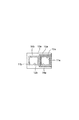
ここで、fθレンズ8aとfθレンズ8bの直径は同一である。また、fθレンズ8a,8bの直径をDとするとき、レーザ2の位置決め領域である加工領域(走査エリア)は、直径Dの円に内接する正方形、すなわち、1辺の長さがD/√2角以下の大きさであり、通常50mmまたは30mm角である。本実施の形態では、図1に示すように、fθレンズ8aとfθレンズ8bの主軸のX座標(第1の軸方向)は同一、Y座標(第2の軸方向)はL(ただし、L>D/√2)だけずれている。
Here, the diameters of the
スキャナ部7a(7b)は、構成が同じである2個のスキャナ7ax,7ay(7bx、7by)からなり、スキャナ7ax(7bx)におけるモータの出力軸の軸線とスキャナ7ay(7by)におけるモータの出力軸の軸線は、直交方向(いわゆるねじれの方向)に配置されている。そして、スキャナ7ax(7bx)はプリント基板等のワーク30上の加工領域(走査エリア)においてレーザ2をX軸方向に走査し、スキャナ7ay(7by)はレーザ2をY軸方向に走査する。
The
位置決め光学系20a,20bはそれぞれ加工ヘッド9a、9bに支持されている。
The positioning
加工ヘッド9aのワーク30と対向する側には、断面が角パイプ状のサポート10aが配置されている。図2に示すように、サポート10aの中空部11aの1辺の長さは、fθレンズ8aの直径で定まる図2中2点鎖線で示す加工領域12aの1辺の長さよりも長い。サポート10aは中空部11aの軸線がfθレンズ8aの主軸と同軸、かつ、加工領域12aを包含するようにして加工ヘッド9aに固定されている。
On the side of the
同様に、加工ヘッド9bのワーク30と対向する側には、断面が角パイプ状のサポート10bが配置されている。サポート10bの中空部11b(図2)の1辺の長さは、fθレンズ8bの直径で定まる図2中2点鎖線で示す加工領域12bの1辺の長さよりも長い。サポート10bは中空部11bの軸線がfθレンズ8bの主軸と同軸、かつ、加工領域12bを包含するようにして加工ヘッド9bに固定されている。
Similarly, a
ところで、本実施の形態では、各位置決め光学系20a,20bのfθレンズ8a,8bから照射されるレーザ2の位置決め領域としての加工領域12a,12bがfθレンズ8a,8bの主軸方向に重ならないように、各fθレンズ8a,8b同士を主軸方向と直交する方向(Y軸方向)にずらして配置している。
By the way, in the present embodiment, the
具体的に説明すると、位置決め光学系20a,20b及びサポート10a,10bを支持している加工ヘッド9a,9b同士を互いに主軸方向と直交する方向(Y軸方向)にずらして配置している。
More specifically, the
そして、本実施の形態のレーザ加工装置100は、ワーク30の表面と裏面に対向させる一対の平板状の遮蔽板13a,13bを備えている。
The
一方の位置決め光学系20a側のサポート10aのワーク30と対向する側には、一方の遮蔽板13aが配置されている。遮蔽板13aには貫通孔14aが形成されている。貫通孔14aの1辺の長さは一方の加工領域12aの1辺の長さよりも長い。つまり、遮蔽板13aには、加工領域12aよりも大きい貫通孔14aが形成されている。遮蔽板13aは、貫通孔14aの軸線がfθレンズ8aの主軸と同軸、かつ、加工領域12aを包含するようにしてサポート10aに固定されている。遮蔽板13aのY軸方向の長さは、少なくともfθレンズ8bの直径で定まる図2に2点鎖線で示す加工領域12bを覆う長さである。つまり、一方の遮蔽板13aは、他方の加工領域12bと対向している。
One
同様に、他方の位置決め光学系20b側のサポート10bのワーク30と対向する側には、他方の遮蔽板13bが配置されている。遮蔽板13bには貫通孔14bが形成されている。貫通孔14bの1辺の長さは他方の加工領域12bの1辺の長さよりも長い。つまり、遮蔽板13bには、加工領域12bよりも大きい貫通孔14bが形成されている。遮蔽板13bは、貫通孔14bの軸線がfθレンズ8bの主軸と同軸、かつ、加工領域12bを包含するようにしてサポート10bに固定されている。遮蔽板13bのY軸方向の長さは、少なくともfθレンズ8aの直径で定まる加工領域12aを覆う長さである。つまり、他方の遮蔽板13bは、一方の加工領域12aと対向している。
Similarly, the
ワーク30は図示を省略するワーク支持装置に支持され、図示を省略する駆動装置により、X,Y軸方向に移動自在である。
The
次に、本実施の形態のレーザ加工装置100の動作を説明する。
Next, the operation of the
レーザ発振器1から出力されたレーザ2は、音響光学素子3により光路を交互に変更されてミラー5a,6aまたはミラー5b,6bを介してスキャナ部7aまたはスキャナ部7bに入射し、それぞれ光路をX,Y軸方向に位置決めされ、fθレンズ8aまたはfθレンズ8bを透過してワーク30に入射し、ワーク30を加工する。なお、このレーザ加工装置は、ワーク30の一方の面だけを加工することもできる。
The
一方の位置決め光学系20aのfθレンズ8aを透過し、さらにワーク30を透過(貫通)したレーザ2は、他方の遮蔽板13bに入射して吸収される(熱に変換される)。同様に、他方の位置決め光学系20bのfθレンズ8bを透過し、さらにワーク30を透過(貫通)したレーザ2は、一方の遮蔽板13aに入射して吸収される(熱に変換される)。
The
つまり、一方の位置決め光学系20aのfθレンズ8aを透過し、さらにワーク30を貫通したレーザ2は、他方の遮蔽板13bで遮蔽され、他方の位置決め光学系20bのfθレンズ8bを透過し、さらにワーク30を貫通したレーザ2は、一方の遮蔽板13aで遮蔽される。
That is, the
このように、それぞれの加工領域12a,12bが主軸方向に重ならないように、2個のfθレンズ8a,8bの主軸を当該主軸と直交する方向にずらせて配置しているので、一方のfθレンズ8aから照射されたレーザ2がワーク30を貫通した際に他方のfθレンズ8bを介してレーザ発振器1に戻ることはなく、他方のfθレンズ8bから照射されたレーザ2がワーク30を貫通した際に一方のfθレンズ8aを介してレーザ発振器1に戻ることはない。したがって、レーザ発振器1を損傷させることがなく、また、ワーク30を裏返しにすることなくワーク30の両面を加工できるので、ランニングコストを低減することができる。
In this way, the main axes of the two
さらに、各遮蔽板13a,13bでワーク30を貫通したレーザ2が遮蔽されるので、レーザ発振器1以外の機器も損傷させることはない。
Furthermore, since the
なお、加工領域12a、12b内の加工が終了したら、ワーク30を移動させ、次の被加工領域を加工領域12a、12bに一致させる。
When the machining in the
以上、上記実施の形態に基づいて本発明を説明したが、本発明はこれに限定されるものではない。 As mentioned above, although this invention was demonstrated based on the said embodiment, this invention is not limited to this.
上記実施の形態では、1つのレーザ発振器1を用いて各位置決め光学系20a,20bにレーザを振り分ける場合について説明したが、レーザ加工装置が各位置決め光学系に対応するように一対のレーザ発振器を備える場合であってもよい。
In the above-described embodiment, the case where the laser is distributed to each positioning
また、上記実施の形態では、fθレンズ8a,8bの主軸をY軸方向にずらす場合について説明したが、X軸方向にずらすようにしてもよい。
In the above-described embodiment, the case where the main axes of the
1 レーザ発振器
7a,7b スキャナ部
8a,8b fθレンズ
12a,12b 位置決め領域(加工領域)
13a,13b 遮蔽板
20a,20b 位置決め光学系
30 ワーク
100 レーザ加工装置
1
13a,
Claims (2)
前記各位置決め光学系は、前記ワークの面に沿う第1の軸方向及び前記第1の軸方向と直交し、前記ワークの面に沿う第2の軸方向にレーザを走査するスキャナ部と、前記スキャナ部を通過したレーザを集光して前記ワークに照射するfθレンズと、を有し、
前記各位置決め光学系の前記fθレンズから照射されるレーザの位置決め領域が前記fθレンズの主軸方向に重ならないように、前記各fθレンズ同士を前記主軸方向と直交する方向にずらして配置した、
ことを特徴とするレーザ加工装置。 A pair of positioning optical systems for positioning a laser output from a laser oscillator at a predetermined position on a plate-like workpiece, the pair of positioning optical systems are arranged to face each other, and one of the pair of positioning optical systems In the laser processing apparatus configured to process the front side of the work, the back side of the work by the other of the pair of positioning optical systems,
Each of the positioning optical systems includes a scanner unit that scans a laser in a first axial direction along the surface of the workpiece and a first axial direction that is perpendicular to the first axial direction and along the surface of the workpiece; and An fθ lens that focuses the laser beam that has passed through the scanner unit and irradiates the workpiece,
The fθ lenses are arranged so as to be shifted in a direction orthogonal to the main axis direction so that the laser positioning region irradiated from the fθ lens of each positioning optical system does not overlap the main axis direction of the fθ lens.
The laser processing apparatus characterized by the above-mentioned.
一方の前記遮蔽板を、他方の前記位置決め領域と対向するように前記一対の位置決め光学系の一方側に配置し、他方の前記位置決め光学系より照射されて前記ワークを貫通したレーザを遮蔽すると共に、
他方の前記遮蔽板を、一方の前記位置決め領域と対向するように前記一対の位置決め光学系の他方側に配置し、一方の前記位置決め光学系より照射されて前記ワークを貫通したレーザを遮蔽する、
ことを特徴とする請求項1に記載のレーザ加工装置。 A pair of shielding plates facing the front and back surfaces of the workpiece;
One of the shielding plates is disposed on one side of the pair of positioning optical systems so as to face the other positioning region, and shields the laser that is irradiated from the other positioning optical system and penetrates the workpiece. ,
The other shielding plate is disposed on the other side of the pair of positioning optical systems so as to face one of the positioning regions, and shields the laser that is irradiated from the one positioning optical system and penetrates the workpiece;
The laser processing apparatus according to claim 1.
Priority Applications (2)
| Application Number | Priority Date | Filing Date | Title |
|---|---|---|---|
| JP2008251342A JP4717916B2 (en) | 2008-09-29 | 2008-09-29 | Laser processing equipment |
| CN200910173567.8A CN101712098B (en) | 2008-09-29 | 2009-09-17 | Laser processing apparatus |
Applications Claiming Priority (1)
| Application Number | Priority Date | Filing Date | Title |
|---|---|---|---|
| JP2008251342A JP4717916B2 (en) | 2008-09-29 | 2008-09-29 | Laser processing equipment |
Publications (2)
| Publication Number | Publication Date |
|---|---|
| JP2010082631A true JP2010082631A (en) | 2010-04-15 |
| JP4717916B2 JP4717916B2 (en) | 2011-07-06 |
Family
ID=42247111
Family Applications (1)
| Application Number | Title | Priority Date | Filing Date |
|---|---|---|---|
| JP2008251342A Expired - Fee Related JP4717916B2 (en) | 2008-09-29 | 2008-09-29 | Laser processing equipment |
Country Status (2)
| Country | Link |
|---|---|
| JP (1) | JP4717916B2 (en) |
| CN (1) | CN101712098B (en) |
Cited By (5)
| Publication number | Priority date | Publication date | Assignee | Title |
|---|---|---|---|---|
| JP2012238354A (en) * | 2011-05-11 | 2012-12-06 | Nhk Spring Co Ltd | Posture correcting device |
| CN103286452A (en) * | 2012-03-02 | 2013-09-11 | 深圳市大族激光科技股份有限公司 | Laser micro hole processing method and laser micro hole processing device |
| CN106298563A (en) * | 2015-05-14 | 2017-01-04 | 比亚迪股份有限公司 | For the apparatus and method that wafer is detected and the method preparing silicon wafer |
| CN106275670A (en) * | 2015-06-24 | 2017-01-04 | 大族激光科技产业集团股份有限公司 | A kind of device utilizing laser technology that heat-shrink tube is marked |
| JPWO2020245956A1 (en) * | 2019-06-05 | 2020-12-10 |
Families Citing this family (3)
| Publication number | Priority date | Publication date | Assignee | Title |
|---|---|---|---|---|
| CN102886606B (en) * | 2012-10-16 | 2015-08-26 | 江苏大学 | A kind of method and apparatus of laser remanufacturing sheet metal weldment |
| CN104238071B (en) * | 2013-06-24 | 2016-12-28 | 大族激光科技产业集团股份有限公司 | A kind of F theta optical lens and laser-processing system |
| WO2016121122A1 (en) * | 2015-01-30 | 2016-08-04 | 株式会社牧野フライス製作所 | Laser processing machine and laser processing method |
Citations (6)
| Publication number | Priority date | Publication date | Assignee | Title |
|---|---|---|---|---|
| JPS63160779A (en) * | 1986-12-24 | 1988-07-04 | Mitsubishi Electric Corp | Energy beam cutting and piercing method |
| JPH03142090A (en) * | 1989-10-27 | 1991-06-17 | Canon Inc | Boring device for printed wiring board |
| JPH0515989A (en) * | 1991-07-09 | 1993-01-26 | Amada Co Ltd | Laser beam machine |
| JPH10314972A (en) * | 1997-05-20 | 1998-12-02 | Sumitomo Heavy Ind Ltd | Laser beam machine |
| JP2004223593A (en) * | 2003-01-24 | 2004-08-12 | Sumitomo Heavy Ind Ltd | Machining planning method and system for biaixal processing machine |
| JP2008080346A (en) * | 2006-09-26 | 2008-04-10 | Sony Corp | Laser beam machining device and laser beam machining method |
Family Cites Families (3)
| Publication number | Priority date | Publication date | Assignee | Title |
|---|---|---|---|---|
| JP4218208B2 (en) * | 1999-03-05 | 2009-02-04 | 三菱電機株式会社 | Laser processing equipment |
| JP4559260B2 (en) * | 2005-03-04 | 2010-10-06 | 日立ビアメカニクス株式会社 | How to drill printed circuit boards |
| JP2008203434A (en) * | 2007-02-19 | 2008-09-04 | Fujitsu Ltd | Scanning mechanism, method of machining material to be machined and machining apparatus |
-
2008
- 2008-09-29 JP JP2008251342A patent/JP4717916B2/en not_active Expired - Fee Related
-
2009
- 2009-09-17 CN CN200910173567.8A patent/CN101712098B/en not_active Expired - Fee Related
Patent Citations (6)
| Publication number | Priority date | Publication date | Assignee | Title |
|---|---|---|---|---|
| JPS63160779A (en) * | 1986-12-24 | 1988-07-04 | Mitsubishi Electric Corp | Energy beam cutting and piercing method |
| JPH03142090A (en) * | 1989-10-27 | 1991-06-17 | Canon Inc | Boring device for printed wiring board |
| JPH0515989A (en) * | 1991-07-09 | 1993-01-26 | Amada Co Ltd | Laser beam machine |
| JPH10314972A (en) * | 1997-05-20 | 1998-12-02 | Sumitomo Heavy Ind Ltd | Laser beam machine |
| JP2004223593A (en) * | 2003-01-24 | 2004-08-12 | Sumitomo Heavy Ind Ltd | Machining planning method and system for biaixal processing machine |
| JP2008080346A (en) * | 2006-09-26 | 2008-04-10 | Sony Corp | Laser beam machining device and laser beam machining method |
Cited By (6)
| Publication number | Priority date | Publication date | Assignee | Title |
|---|---|---|---|---|
| JP2012238354A (en) * | 2011-05-11 | 2012-12-06 | Nhk Spring Co Ltd | Posture correcting device |
| CN103286452A (en) * | 2012-03-02 | 2013-09-11 | 深圳市大族激光科技股份有限公司 | Laser micro hole processing method and laser micro hole processing device |
| CN106298563A (en) * | 2015-05-14 | 2017-01-04 | 比亚迪股份有限公司 | For the apparatus and method that wafer is detected and the method preparing silicon wafer |
| CN106275670A (en) * | 2015-06-24 | 2017-01-04 | 大族激光科技产业集团股份有限公司 | A kind of device utilizing laser technology that heat-shrink tube is marked |
| JPWO2020245956A1 (en) * | 2019-06-05 | 2020-12-10 | ||
| WO2020245956A1 (en) * | 2019-06-05 | 2020-12-10 | 三菱重工業株式会社 | Laser machining method and laser machining device |
Also Published As
| Publication number | Publication date |
|---|---|
| CN101712098B (en) | 2014-09-10 |
| CN101712098A (en) | 2010-05-26 |
| JP4717916B2 (en) | 2011-07-06 |
Similar Documents
| Publication | Publication Date | Title |
|---|---|---|
| JP4717916B2 (en) | Laser processing equipment | |
| JP4765378B2 (en) | Laser processing equipment | |
| JP4459530B2 (en) | Laser processing equipment | |
| JP5025158B2 (en) | Laser processing method and apparatus | |
| JP5133033B2 (en) | Laser processing equipment | |
| JP3479878B2 (en) | Laser processing method and processing apparatus | |
| CN102245341A (en) | Controlling dynamic and thermal loads on laser beam positioning system to achieve high throughput laser processing of workpiece features | |
| TW200731363A (en) | Laser beam processing machine | |
| CN101971099A (en) | Laser processing a multi-device panel | |
| JP2008279503A (en) | Multi-laser system | |
| CN102844142B (en) | Laser-machining device, laser-machining method, and laser-machining control device | |
| KR20130027258A (en) | Laser processing apparatus | |
| JP2005177788A (en) | Laser beam machining apparatus | |
| CN108213743B (en) | Laser processing device and laser processing method | |
| JP2003112278A (en) | Machining device and method | |
| JP3682295B2 (en) | Laser processing equipment | |
| JP2017042808A (en) | Laser processing device | |
| JP2003126982A (en) | Method and device for laser beam machining | |
| JP2014183152A (en) | Via hole formation method and desmear device | |
| JP2010023100A (en) | Laser beam machining apparatus and laser beam machining method | |
| JP3237832B2 (en) | Laser processing apparatus and laser drilling method | |
| JP2013071136A (en) | Laser beam machining apparatus | |
| KR20210114873A (en) | Control Device of Laser Processing Apparatus, Laser Processing Apparatus, and Laser Processing Method | |
| JP4948923B2 (en) | Beam irradiation apparatus and beam irradiation method | |
| KR101787525B1 (en) | Laser processing apparatus and laser processing method using the laser processing apparatus |
Legal Events
| Date | Code | Title | Description |
|---|---|---|---|
| A621 | Written request for application examination |
Free format text: JAPANESE INTERMEDIATE CODE: A621 Effective date: 20100915 |
|
| A977 | Report on retrieval |
Free format text: JAPANESE INTERMEDIATE CODE: A971007 Effective date: 20101214 |
|
| A131 | Notification of reasons for refusal |
Free format text: JAPANESE INTERMEDIATE CODE: A131 Effective date: 20101221 |
|
| A521 | Request for written amendment filed |
Free format text: JAPANESE INTERMEDIATE CODE: A523 Effective date: 20110218 |
|
| TRDD | Decision of grant or rejection written | ||
| A01 | Written decision to grant a patent or to grant a registration (utility model) |
Free format text: JAPANESE INTERMEDIATE CODE: A01 Effective date: 20110329 |
|
| A01 | Written decision to grant a patent or to grant a registration (utility model) |
Free format text: JAPANESE INTERMEDIATE CODE: A01 |
|
| A61 | First payment of annual fees (during grant procedure) |
Free format text: JAPANESE INTERMEDIATE CODE: A61 Effective date: 20110330 |
|
| R150 | Certificate of patent or registration of utility model |
Ref document number: 4717916 Country of ref document: JP Free format text: JAPANESE INTERMEDIATE CODE: R150 Free format text: JAPANESE INTERMEDIATE CODE: R150 |
|
| FPAY | Renewal fee payment (event date is renewal date of database) |
Free format text: PAYMENT UNTIL: 20140408 Year of fee payment: 3 |
|
| S533 | Written request for registration of change of name |
Free format text: JAPANESE INTERMEDIATE CODE: R313533 |
|
| R350 | Written notification of registration of transfer |
Free format text: JAPANESE INTERMEDIATE CODE: R350 |
|
| S531 | Written request for registration of change of domicile |
Free format text: JAPANESE INTERMEDIATE CODE: R313532 |
|
| R350 | Written notification of registration of transfer |
Free format text: JAPANESE INTERMEDIATE CODE: R350 |
|
| S531 | Written request for registration of change of domicile |
Free format text: JAPANESE INTERMEDIATE CODE: R313531 |
|
| R350 | Written notification of registration of transfer |
Free format text: JAPANESE INTERMEDIATE CODE: R350 |
|
| LAPS | Cancellation because of no payment of annual fees |