JP2010078435A - Apparatus for measuring magnetic field distribution - Google Patents
Apparatus for measuring magnetic field distribution Download PDFInfo
- Publication number
- JP2010078435A JP2010078435A JP2008246563A JP2008246563A JP2010078435A JP 2010078435 A JP2010078435 A JP 2010078435A JP 2008246563 A JP2008246563 A JP 2008246563A JP 2008246563 A JP2008246563 A JP 2008246563A JP 2010078435 A JP2010078435 A JP 2010078435A
- Authority
- JP
- Japan
- Prior art keywords
- temperature
- magnetic field
- measurement object
- measurement
- magnetic
- Prior art date
- Legal status (The legal status is an assumption and is not a legal conclusion. Google has not performed a legal analysis and makes no representation as to the accuracy of the status listed.)
- Granted
Links
- 230000004907 flux Effects 0.000 claims abstract description 18
- 238000005259 measurement Methods 0.000 claims description 121
- 239000000523 sample Substances 0.000 claims description 8
- 230000007246 mechanism Effects 0.000 description 7
- 238000000034 method Methods 0.000 description 7
- 230000008569 process Effects 0.000 description 6
- 238000012545 processing Methods 0.000 description 6
- 230000003028 elevating effect Effects 0.000 description 5
- XEEYBQQBJWHFJM-UHFFFAOYSA-N Iron Chemical compound [Fe] XEEYBQQBJWHFJM-UHFFFAOYSA-N 0.000 description 2
- 238000010586 diagram Methods 0.000 description 2
- 239000011810 insulating material Substances 0.000 description 2
- 238000012986 modification Methods 0.000 description 2
- 230000004048 modification Effects 0.000 description 2
- 229910052692 Dysprosium Inorganic materials 0.000 description 1
- 229910052779 Neodymium Inorganic materials 0.000 description 1
- 238000013459 approach Methods 0.000 description 1
- 230000008859 change Effects 0.000 description 1
- 230000005347 demagnetization Effects 0.000 description 1
- 238000011161 development Methods 0.000 description 1
- KBQHZAAAGSGFKK-UHFFFAOYSA-N dysprosium atom Chemical compound [Dy] KBQHZAAAGSGFKK-UHFFFAOYSA-N 0.000 description 1
- 230000000694 effects Effects 0.000 description 1
- 229910052742 iron Inorganic materials 0.000 description 1
- 230000005389 magnetism Effects 0.000 description 1
- QEFYFXOXNSNQGX-UHFFFAOYSA-N neodymium atom Chemical compound [Nd] QEFYFXOXNSNQGX-UHFFFAOYSA-N 0.000 description 1
- 230000000149 penetrating effect Effects 0.000 description 1
- 230000002093 peripheral effect Effects 0.000 description 1
- 230000001681 protective effect Effects 0.000 description 1
- 229910000859 α-Fe Inorganic materials 0.000 description 1
Images


Landscapes
- Measuring Magnetic Variables (AREA)
Abstract
Description
本発明は、測定対象物の周囲に発生する磁場(磁界)の分布を測定する磁場分布測定装置に関する。 The present invention relates to a magnetic field distribution measuring apparatus that measures the distribution of a magnetic field (magnetic field) generated around a measurement object.
従来から、測定対象物の周囲に発生する磁場の分布を測定する磁場分布測定装置が知られている。周囲に磁場を発生させる測定対象物としては、例えば、磁石や磁石を内蔵した部品などが挙げられる。 2. Description of the Related Art Conventionally, a magnetic field distribution measurement device that measures the distribution of a magnetic field generated around a measurement object is known. Examples of the measurement object that generates a magnetic field around it include a magnet and a part incorporating the magnet.
ところで、一般的な自動車用のモータには、磁石が多く使用されている。自動車は、低温の環境や高温の環境に曝されるが、置かれた環境でモータを正常に動作させる必要がある。そのため、自動車用のモータに用いられる磁石は、低温や高温の環境に左右されずに磁力を保たなくてはならない。 By the way, many magnets are used in general motors for automobiles. An automobile is exposed to a low temperature environment or a high temperature environment, but it is necessary to operate the motor normally in the environment in which the vehicle is placed. For this reason, magnets used in motors for automobiles must maintain a magnetic force without being influenced by low or high temperature environments.
例えば、NdFe(ネオジウム・鉄)系磁石は、100℃程度の高温になると減磁が激しいため、ディスプロシウム(Dysprosium)などを用いて減磁を抑制する技術が開発されている。また、フェライト磁石は、温度の低下とともに減磁するため、特性の改善に向けて開発が進められている。 For example, NdFe (neodymium / iron) -based magnets are severely demagnetized at temperatures as high as about 100 ° C., and therefore a technique for suppressing demagnetization using dysprosium or the like has been developed. In addition, since ferrite magnets demagnetize with a decrease in temperature, development is being promoted to improve characteristics.
従来の磁場の分布を測定する装置としては、例えば、特許文献1に記載されているようなものがある。特許文献1には、測定対象物の周囲に生じている磁界を可視化表示する磁界測定装置に関するものが記載されている。この特許文献1に記載された磁界測定装置では、磁気センサを備えた測定器によって測定対象物の三次元磁力データを測定する。そして、測定した三次元磁力データに基づいてコンピュータが磁界の状態を可視化表示できるようにデータを加工するようになっている。
As a conventional apparatus for measuring the distribution of a magnetic field, for example, there is an apparatus described in
しかしながら、特許文献1に記載された磁界測定装置などの従来の磁場分布測定装置は、室温の環境下で測定対象物の周囲に発生する磁場の分布を測定するものであった。そのため、実際に使用される環境で磁場がどのように分布するか、或いは磁力がどのように変化するかを確認することができないという問題があった。例えば、自動車のモータに使用される磁石は、−50℃から200℃の範囲で磁場の分布を測定する必要がある。
However, a conventional magnetic field distribution measuring device such as the magnetic field measuring device described in
本発明は、このような状況に鑑みてなされたものであり、測定対象物の温度を可変制御し、予め設定された温度になった測定対象物の周囲に発生する磁場の分布を測定することを目的とする。 The present invention has been made in view of such circumstances, and variably controls the temperature of the measurement object, and measures the distribution of the magnetic field generated around the measurement object at a preset temperature. With the goal.
本発明の磁場分布測定装置は、測定器と、恒温槽と、アクチュエータと、温度センサと、制御部とを備えている。測定器は、測定対象物から発せられる磁束を検出する磁気センサを有し、この磁気センサによって検出された磁束に基づいて磁場を測定する。恒温槽は、測定対象物と磁気センサを収容する測定室と、測定室内の温度を調整する温度調整部を有している。アクチュエータは、測定室に収容された磁気センサを三次元方向に移動させる。温度センサは、測定対象物の温度を検出する。制御部は、温度センサによって検出された測定対象物の温度が予め設定した温度になると、アクチュエータを制御して磁気センサを移動させ、測定対象物の周囲に生じる磁場の分布を測定させる。 The magnetic field distribution measuring apparatus of the present invention includes a measuring instrument, a thermostatic chamber, an actuator, a temperature sensor, and a control unit. The measuring device has a magnetic sensor that detects a magnetic flux emitted from a measurement object, and measures a magnetic field based on the magnetic flux detected by the magnetic sensor. The thermostat has a measurement chamber that houses the measurement object and the magnetic sensor, and a temperature adjustment unit that adjusts the temperature in the measurement chamber. The actuator moves the magnetic sensor accommodated in the measurement chamber in a three-dimensional direction. The temperature sensor detects the temperature of the measurement object. When the temperature of the measurement object detected by the temperature sensor reaches a preset temperature, the control unit controls the actuator to move the magnetic sensor to measure the distribution of the magnetic field generated around the measurement object.
本発明の磁場分布測定装置では、恒温槽によって測定対象物の温度を変化させ、測定対象物が予め設定した温度になると、アクチュエータを制御して測定器の磁気センサを移動させ、測定対象物の磁場分布を測定する。 In the magnetic field distribution measuring apparatus of the present invention, the temperature of the measurement object is changed by the thermostat, and when the measurement object reaches a preset temperature, the actuator is controlled to move the magnetic sensor of the measuring instrument, Measure the magnetic field distribution.
本発明の磁場分布測定装置によれば、測定対象物の温度を予め設定した温度に変化させることができ、設定した温度になった測定対象物の周囲に発生する磁場の分布を測定することができる。 According to the magnetic field distribution measuring apparatus of the present invention, the temperature of the measurement object can be changed to a preset temperature, and the distribution of the magnetic field generated around the measurement object at the set temperature can be measured. it can.
以下、本発明の磁場分布測定装置を実施するための最良の形態について、図面を参照して説明するが、本発明は以下の形態に限定されるものではない。 Hereinafter, the best mode for carrying out the magnetic field distribution measuring apparatus of the present invention will be described with reference to the drawings, but the present invention is not limited to the following modes.
[磁場分布測定装置の構成例]
まず、本発明の磁場分布測定装置の一実施形態の構成について、図1及び図2を参照して説明する。
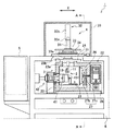
図1は、本発明の磁場分布測定装置の一実施形態を正面から見た部分断面図である。図2は、本発明の磁場分布測定装置の一実施形態を図1に示すA−A線で切断した断面図である。
[Configuration example of magnetic field distribution measurement device]
First, the configuration of an embodiment of the magnetic field distribution measuring apparatus of the present invention will be described with reference to FIGS. 1 and 2.
FIG. 1 is a partial cross-sectional view of an embodiment of the magnetic field distribution measuring apparatus of the present invention as viewed from the front. FIG. 2 is a cross-sectional view taken along the line AA shown in FIG.
磁場分布測定装置1は、測定対象物101の周囲に生じる磁場分布を測定する測定器2と、測定対象物101が収容される恒温槽3と、アクチュエータ4と、制御装置5と、恒温槽3とアクチュエータ4及び制御装置5が設置される基台6を備えている。
The magnetic field
測定器2は、測定対象物101から発せられる磁束を検出する磁気センサ11と、計量器12(図7を参照)から構成されている。磁気センサ11と計量器12は、図示しないケーブルによって電気的に接続されている。
The
本実施の形態では、測定器2として、第1の測定器と、第2の測定器を採用している。第1の測定器は、磁気センサ11としてホールプローブを適用し、計量器12としてテスラメータを適用する。この第1の測定器では、ホールプローブによって検出された磁束をテスラメータで磁束密度に変換し、その磁束密度に基づいて測定対象物101の周囲に生じる磁場分布を測定する。
In the present embodiment, a first measuring instrument and a second measuring instrument are employed as the
一方、第2の測定器は、磁気センサ11としてサーチコイルを適用し、計量器12としてフラックスメータを適用する。この第2の測定器では、サーチコイルによって検出された磁束をフラックスメータで磁測量に変換し、その磁測量に基づいて測定対象物101の周囲に生じる磁場分布を測定する。
On the other hand, the second measuring device uses a search coil as the
第1の測定器と第2の測定器は、どちらか一方が選択されて使用される。例えば、第1の測定器を使用する場合は、磁気センサ11の第1の具体例を示すホールプローブをアクチュエータ4の後述するセンサ保持部31に取り付ける。そして、図示しないケーブルの接続先を計量器12の第1の具体例を示すテスタメータにする。一方、第2の測定器を使用する場合は、磁気センサ11の第2の具体例を示すサーチコイルをセンサ保持部31に取り付け、ケーブルの接続先を計量器12の第2の具体例を示すフラックスメータにする。
Either the first measuring instrument or the second measuring instrument is selected and used. For example, when the first measuring device is used, a Hall probe showing a first specific example of the
使用する測定器の選択は、例えば、測定する磁場分布の範囲や、磁場分布を測定するときの測定対象物101の温度(予め設定する温度)によって決定される。本実施の形態では、磁場分布を測定するときの測定対象物101の温度が100℃より小さいときに第1の測定器を使用し、測定対象物101の温度が100℃以上のときに第2の測定器を使用する。
The selection of the measuring instrument to be used is determined, for example, by the range of the magnetic field distribution to be measured and the temperature of the
これは、第1の測定器のホールプローブが、約100℃の気温まで使用可能な設定になっているからである。したがって、100℃以上の気温でも使用できるホールプローブが開発された場合は、第1の測定器と第2の測定器を選択するための温度の基準を変更してもよい。 This is because the hall probe of the first measuring instrument is set to be usable up to an air temperature of about 100 ° C. Therefore, when a hall probe that can be used even at an air temperature of 100 ° C. or higher is developed, the temperature reference for selecting the first measuring device and the second measuring device may be changed.
なお、ホールプローブやサーチコイルを適用した磁気センサ11は、磁気の1方向の成分を測定するように構成してもよく、2方向や3方向の成分を同時に測定するように構成してもよい。上述した1方向としては、例えば、Z方向(図2を参照)に設定し、3方向としては、例えば、X方向、Y方向及びZ方向(図1及び図2を参照)に設定する。
The
恒温槽3は、測定対象物101と測定器2の磁気センサ11が収容される測定室21と、この測定室21内の温度を調整する温度調整部22を有している。測定室21は、断熱材料によって形成されたケース本体23と、アクチュエータ4と一緒に水平方向に移動するケース蓋24から形成されている。
The
ケース本体23は、略四角形の筐体からなり、上面に開口部23aを有している。ケース本体23の開口部23aには、アクチュエータ4の一部が挿通されており、このアクチュエータ4の一部に測定器2の磁気センサ11が取り付けられている。ケース本体23の上面には、開口部23aを囲う摺動突部23bが設けられている。この摺動突部23bには、ケース蓋24が摺動可能に当接される。
The case
ケース蓋24は、扁平な板体からなっている。このケース蓋24の平面は、ケース本体23の摺動突部23bよりも大きく設定されている。そのため、アクチュエータ4と一緒に水平方向に移動しても、ケース蓋24が常に開口部23aを閉じるようになっている。このケース蓋24とケース本体23は、測定室21内の熱が外部に放熱されないように、断熱材料によって形成されている。
The
温度調整部22は、ヒータ26と、送風ファン27と、ヒータ26及び送風ファン27を駆動させる温度制御装置28とを備えている。温度制御装置28は、ケース本体23の側部に配置されており、ケーブル(図示せず)によって制御装置5と電気的に接続されている。ヒータ26は、測定室21内に配置されている。このヒータ26の一端部は、ケース本体23を貫通して温度制御装置28に接続されている。
The
送風ファン27は、ケース本体23を貫通する回転軸27aと、この回転軸27aの一端に設けられ、ヒータ26の近傍に配置されるプロペラ27bと、回転軸27aの他端に設けられ、温度制御装置28内に配設されるモータ(図示せず)を有している。ヒータ26によって温められた気体は、送風ファン27によって測定室21内を循環する。その結果、測定室21内の温度が上昇し、測定室21内に収容された測定対象物101が温められる。
The
温度制御装置28は、後述する温度センサ13によって検出される測定対象物101の温度(以下、「実測温度」という)が、制御装置5で予め設定される温度(以下、「設定温度」という)になるように、ヒータ26及び送風ファン27の駆動を制御する。
In the
以下の説明においては、基台6の幅方向をX方向(図1を参照)とし、基台6の奥行き方向をY方向(図2を参照)とする。そして、基台6の高さ方向をZ方向とする。
In the following description, the width direction of the
アクチュエータ4は、センサ保持部31と、支持部材32と、第1の移動枠33と、第2の移動枠34と、ベース枠35を備えている。このアクチュエータ4の支持部材32と、第1の移動枠33と、第2の移動枠34と、ベース枠35は、基台6の上部に設けられた保護ケース30によって覆われている。
The actuator 4 includes a
センサ保持部31は、Z軸方向に延びる細長の部材からなり、上述したケース蓋24を貫通している。このセンサ保持部31の一端には、磁気センサ11が着脱可能に取り付けられている。さらに、センサ保持部31の一端には、測定対象物101の表面の温度を検出する温度センサ13が取り付けられている。一方、センサ保持部31の他端は、支持部材32に支持されている。
The
支持部材32は、センサ保持部31の他端が固定される昇降部32aと、この昇降部32aをZ方向に案内するガイド部32bを有しており、センサ保持部31をZ方向に移動可能に支持している。この支持部材32は、ガイド部32bが第1の移動枠33に固定されることにより、基台6の上方に配置されている。
The
第1の移動枠33は、支持部材32を固定する上面と、この上面に対向する底面を有する枠体からなっている。この第1の移動枠33の上面及び底面は、X方向とY方向を含む水平方向に平行な面となっている。第1の移動枠33の底面には、ケース蓋24が固定される蓋固定部33aが設けられている。
The first moving
蓋固定部33aは、第1の移動枠33の開口部の周囲から突出する筒状に形成されている。この蓋固定部33aの筒穴には、センサ保持部31が移動可能に挿通されている。そして、蓋固定部33aは、第2の移動枠34の開口部と、ベース枠35の開口部を貫通しており、ベース枠35の下方に突出する先端部にケース蓋24が固定されている。
The
第2の移動枠34は、第1の移動枠33と同様な形状の枠体となっており、第1の移動枠33の下方に配置されている。この第2の移動枠34は、第1の移動枠33をX方向に移動可能に支持している。ベース枠35は、第1の移動枠33と同様な形状の枠体となっており、基台6の上部に固定されている。このベース枠35は、第2の移動枠34をY方向に移動可能に支持している。
The second moving
アクチュエータ4は、第1の移動枠33を移動させる第1の駆動部(図示せず)と、第2の移動枠34を移動させる第2の駆動部(図示せず)と、支持部材32の昇降部32aを移動させる第1の駆動部(図示せず)を有している。これら3つの駆動部は、モータと、このモータの回転を直線運動に変換する移動機構からなっている。この移動機構としては、例えば、送りネジ機構、ラック・ピニオン機構、ベルト送り機構、ワイヤ送り機構その他の機構を適用することもできる。
The actuator 4 includes a first driving unit (not shown) that moves the first moving
例えば、第1の駆動部によって第1の移動枠33をX方向に移動させると、支持部材32及びセンサ保持部31が第1の移動枠33と一緒にX方向に移動する。これにより、センサ保持部31に取り付けられた磁気センサ11及び温度センサ13がX方向に移動する。
For example, when the first moving
このとき、蓋固定部33aに固定されたケース蓋24が、第1の移動枠33と一緒にX方向に移動する。ケース蓋24は、ケース本体23の摺動突部23bよりも大きく設定されているため、ケース本体23の開口部23aは、ケース蓋24によって常に閉じられている。
At this time, the
一方、第2の駆動部によって第2の移動枠34をY方向に移動させると、第2の移動枠34に支持された第1の移動枠33がY方向に移動する。その結果、センサ保持部31に取り付けられた磁気センサ11及び温度センサ13がY方向に移動する。このとき、ケース蓋24が第1の移動枠33と一緒にY方向に移動するが、ケース本体23の開口部23aは、ケース蓋24によって常に閉じられている。
On the other hand, when the second moving
なお、第3の駆動部によって支持部材32の昇降部32aをZ方向に移動させると、センサ保持部31に取り付けられた磁気センサ11及び温度センサ13がZ方向に移動する。
Note that when the elevating
次に、測定対象物101を支持する支持台について、図3及び図4を参照して説明する。
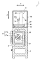
図3は恒温槽3の測定室21に配置された支持台を示す断面図、図4は恒温槽を図3に示すB−B線で切断した断面図である。
Next, a support table that supports the
FIG. 3 is a cross-sectional view showing a support base disposed in the
恒温槽3の測定室21には、測定対象物101を支持する支持台41が配置されている。この支持台41は、ケース本体23をX方向に貫通する回転駆動部42によって回転可能に構成されている。
In the
支持台41は、台本体43と、この台本体43に設けられた挟持部44A,44Bを備えている。台本体43は、略円柱状に形成されており、その軸心がX方向に延びるように配置されている。この台本体43の一方の平面部は、回転駆動部42の後述する回転軸47に固定されている。台本体43の他方の平面部には、測定対象物101に設けられたシャフト101aが挿通される円形の凹部43aが形成されている。この凹部43aの中心は、台本体43の軸心に一致している。
The
また、台本体43の他方の平面部には、凹部43aを囲うようにして配置された挟持部44A,44Bが設けられている。この挟持部44A,44Bは、互いに接近及び離反可能に設けられており、測定対象物101のシャフト101aを挟持するようになっている。この挟持部44A,44Bによってシャフト101aを挟持することにより、測定対象物101が支持台41に固定される。このとき、測定対象物101は、その軸心(シャフト101aの軸心)が台本体43の中心と一致するように固定される。
Further, on the other plane portion of the
回転駆動部42は、ケース本体23の外側に配置されるモータ46と、このモータ46によって回転される回転軸47を備えている。モータ46は、基台6に取り付けられたモータベース48に固定されている。回転軸47は、ケース本体23の側部をX方向に貫通しており、この回転軸47の先端に支持台41の台本体43が固定されている。そして、台本体43は、その中心が回転軸47の軸心と一致している。
The
回転駆動部42のモータ46は、制御装置5(図1を参照)によって駆動される。この回転駆動部42によって支持台41を回転させることにより、測定対象物101がX方向に延びる軸を中心に回転する。そして、回転する測定対象物101に磁気センサ11を接近させることにより、測定対象物101を回転させながら測定対象物101の周囲に生じる磁場の分布を測定することができる。
The
恒温槽3の測定室21には、調整台51と、調整台51をX方向に移動させる移動台52が設けられている。調整台51は、縦長の直方体からなり、上面に略V字状に形成された係合溝51aを有している(図4を参照)。この係合溝51aには、測定対象物101のシャフト101aが設けられた面と反対側の面に形成された軸突部101bの周面が係合される。また、調整台51は、高さが変更可能に構成されている。
The
調整台51の係合溝51aに測定対象物101の軸突部101bを係合させることにより、測定対象物101の回転中心の振れを補正したり、磁気センサ11に対する測定対象物101の回転中心の平行度の精度を高めたりすることができる。
By engaging the
調整台51は、移動台52に固定されている。移動台52は、測定室21に設けられたベース板53上をX方向に移動可能に構成されている。そして、支持台41に測定対象物101を固定しない場合は、移動台52によって調整台51を支持台41から最も離れた位置である待機位置(図5を参照)に移動させる。
The adjustment table 51 is fixed to the moving table 52. The moving table 52 is configured to be movable in the X direction on a
次に、測定対象物101を載置する載置台について、図5及び図6を参照して説明する。
図5は恒温槽3の測定室21に配置された載置台を示す断面図、図6は恒温槽3を図5に示すC−C線で切断した断面図である。
Next, a mounting table on which the
FIG. 5 is a cross-sectional view showing a mounting table disposed in the
磁場分布測定装置1は、支持台41に測定対象物を固定しない場合に、その測定対象物を載置する載置台55を備えている。この載置台55は、下面がベース板53の上面に対向する調整板55aと、この調整板55aの上面に設けられた載置テーブル55bからなり、ベース板53に対して着脱可能に構成されている。図5に示すように、載置台55をベース板53に取り付ける場合は、移動台52によって調整台51を待機位置に移動させる。
The magnetic field
載置台55は、調整板55aを貫通する3つの傾き調整用ねじ56によってベース板53に取り付けられている。3つの傾き調整用ねじ56は、中間部に調整板55aを支持する止め輪(図示せず)を有している。そのため、載置台55がベース板53に取り付けられた状態において、調整板55aの下面とベース板53の上面との間には、所定の間隙が形成されている。
The mounting table 55 is attached to the
3つの傾き調整用ねじ56は、調整板55aにおいて、中心が載置テーブル55bの中心と一致する三角形の3つの頂点を貫通している。つまり、少なくとも2つの傾き調整用ねじ56のベース板53から突出する高さを変えることにより、載置台55の傾きが調整される。
The three
本実施の形態では、3つの傾き調整用ねじ56のうちの2つの傾き調整用ねじ56が、基台6に設けられた傾き調整用ハンドル57A,57Bとフレキシブルケーブル59を介して連結されている(図6を参照)。したがって、傾き調整用ハンドル57A,57Bを回転させると、2つの傾き調整用ねじ56が回転させることができる。その結果、2つの傾き調整用ねじ56のベース板53から突出する高さを変化させて、載置台55の傾きを調整することができる。
In the present embodiment, two of the three
[制御回路の構成例]
次に、制御装置5の制御回路について図7を参照して説明する。
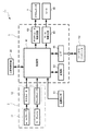
図5は、制御装置5の制御回路例を示すブロック図である。
[Configuration example of control circuit]
Next, a control circuit of the
FIG. 5 is a block diagram illustrating a control circuit example of the
制御装置5は、制御部61と、記憶部62と、アクチュエータ駆動回路63と、モータ駆動回路64を備えている。
The
制御部61は、例えば、中央演算処理装置(CPU)を有する演算回路等を備えている。この制御部61には、記憶部62と、アクチュエータ駆動回路63と、モータ駆動回路64と、インタフェース(I/F)65と、温度センサ13と、測定器2のテスラメータ及びフラックスメータが接続されている。
The
インタフェース(I/F)65には、制御装置5に設けられた接続端子66が接続されている。この接続端子66には、ケーブルを介して外部装置の一具体例を示すパーソナルコンピュータ110が接続されている。
A connection terminal 66 provided in the
記憶部62は、ROM(Read Only Memory)と、RAM(Random Access Memory)を有している。ROMには、制御部61において実行されるプログラムや、その処理に必要なデータ等が記憶されている。RAMは、制御部61がプログラムを実行する際に一時的にデータを記憶するために使用される。
The
制御部61には、パーソナルコンピュータ110を介して磁場分布の測定に必要な各種設定値が供給される。設定値としては、例えば、測定対象物101の設定温度や、支持台41の使用の有無などを挙げることができる。なお、制御装置5に設定部を設け、この設定部によって磁場分布の測定に必要な各種設定値を設定してもよい。
Various setting values necessary for measuring the magnetic field distribution are supplied to the
制御部61は、パーソナルコンピュータ110から供給された測定対象物101の設定温度と、温度センサ13によって検出された実測温度を温度制御装置28に出力する。温度制御装置28は、供給された設定温度と、実測温度に基づいてヒータ26及び送風ファン27の駆動を制御する。
The
制御部61は、温度センサ13によって検出された実測温度が設定温度に達すると、アクチュエータ駆動回路63とモータ駆動回路64に制御信号を出力する。アクチュエータ駆動回路63とモータ駆動回路64は、制御部61から出力される制御信号を受けて、それぞれアクチュエータ4とモータ46を動作させる。これにより、測定対象物101の周囲に生じる磁場の分布が測定器2によって測定される。
When the measured temperature detected by the
また、制御部61は、測定器2の計量器12(テスラメータ或いはフラックスメータ)から供給される磁場分布の測定データを記憶部62に記憶させる。また、供給される磁場分布の測定データをインタフェース(I/F)65を介してパーソナルコンピュータ110に出力する。なお、磁場分布の測定データを測定器2からパーソナルコンピュータ110に直接出力する構成であってもよい。
In addition, the
磁場分布測定装置1によって測定された磁場分布の測定データをパーソナルコンピュータ110に供給することにより、測定データの解析を行うことができる。また、測定データから三次元グラフを作成してモニタに表示したりプリンタで印刷したりすることができる。
By supplying measurement data of the magnetic field distribution measured by the magnetic field
[制御部の処理例]
次に、制御部61により行われる制御処理の例について図8を参照して説明する。
図8は、制御部61により行われる制御処理の例を示すフローチャートである。
[Example of control unit processing]
Next, an example of control processing performed by the
FIG. 8 is a flowchart illustrating an example of control processing performed by the
初めに、制御部61は、測定対象物101の設定温度が入力された否かを判別する(ステップS1)。設定温度が入力されていないと判別したとき、制御部61は、再び処理をステップS1に移し、設定温度の入力を待つ。
First, the
一方、設定温度が入力されたと判別したとき、制御部61は、設定温度を温度制御装置28(図1を参照)に出力する(ステップS2)。次に、制御部61は、温度センサ13によって検出された測定対象物101の表面の温度(実測温度)を温度制御装置28に出力する(ステップS3)。
On the other hand, when determining that the set temperature has been input, the
測定対象物101の表面の温度を検出するには、制御部61がアクチュエータ駆動回路63に制御信号を出力し、温度センサ13を測定対象物101の近傍に配置又は接触させる。温度制御装置28は、制御部61から出力された設定温度と実測温度の情報に基づいて、ヒータ26及び送風ファン27を動作させ、恒温槽3の測定室21内の温度を変化させる。
In order to detect the temperature of the surface of the
制御部61は、ステップS3の処理を終えてから所定の時間が経過すると、実測温度が設定温度に達したか否かを判別する。実測温度が設定温度に達していないと判別したとき、制御部61は、処理を再びステップS3に移し、検出された実測温度を温度制御装置28に出力する。
The
一方、実測温度が設定温度に達したと判別したとき、制御部61は、今回の測定において支持台41を使用するか否かを判別する(ステップS5)。この支持台41を使用するか否かの情報は、設定温度などの各種設定と同様に入力される。なお、支持台41にセンサを設け、支持台41に測定対象物101が固定されたことを検出するようにしてもよい。
On the other hand, when determining that the actually measured temperature has reached the set temperature, the
判断ステップS5の処理において、支持台41を使用しないと判別したとき、制御部61は、処理をステップS7に移す。一方、支持台41を使用すると判別したとき、制御部61は、モータ駆動回路64(図7を参照)を介して回転駆動部42のモータ46を駆動させる(ステップS6)。これにより、支持台41に固定された測定対象物101が測定室21内で回転される。
When it is determined that the
回転駆動部42のモータ46を駆動させた後、或いはステップS5の処理で支持台41を使用しないと判別したとき、制御部61は、アクチュエータ駆動回路63を介してアクチュエータ4を駆動させる(ステップS7)。これにより、磁気センサ11が測定対象物101に接近した状態で移動し、測定対象物101の周囲に生じる磁場の分布が測定される。
After driving the
次に、制御部61は、磁場分布の測定データを記憶部62に記憶させると共に、インタフェース(I/F)65を介してパーソナルコンピュータ110に出力する(ステップS8)。全ての測定データの記憶及び出力を終えると、制御部61は、制御処理を終了する。
Next, the
[実施形態の変形例]
本発明は、前述しかつ図面に示した実施の形態に限定されるものではなく、その要旨を逸脱しない範囲内で種々の変形実施が可能である。例えば、上述した実施の形態においては、温度センサ13をアクチュエータ4のセンサ保持部31に取り付ける構成としたが、本発明に係る温度センサとしては、支持台41及び載置台55に設ける構成としてもよい。
[Modification of Embodiment]
The present invention is not limited to the embodiment described above and shown in the drawings, and various modifications can be made without departing from the scope of the invention. For example, in the above-described embodiment, the
上述した実施形態では、測定器2としてホールプローブとテスラメータからなる第1の測定器と、サーチコイルとフラックスメータからなる第2の測定器の2つの測定器を採用する構成とした。しかしながら、本発明に係る測定器としては、どちらか一方の測定器を採用する構成としてもよい。
In the above-described embodiment, the measuring
上述した実施形態では、測定対象物101を回転させる支持台41と、測定対象物101を載置する載置台55を備える構成とたが、どちらか一方の台を備える構成としてもよい。
In the above-described embodiment, the support table 41 that rotates the
上述した実施形態では、温度調整部22がヒータ26を備える構成とすることにより、測定室21内の温度を温めるようにしたが、本発明に係る温度調整部としては、ヒータ26の他に冷却用の熱交換器を備える構成としてもよい。このように温度調整部を構成すると、測定室21内の温度をヒータによって温めたり、熱交換器で冷却したりすることができる。そして、測定室21内の温度及び測定対象物101の温度を測定室21の外部の温度(室温)より低くすることができる。
In the embodiment described above, the
[実施の形態の効果]
上述した実施の形態の磁場分布測定装置1によれば、恒温槽3の測定室21内の温度を変化させることにより、測定室21に収容される測定対象物101の温度を予め設定される設定温度に変化させることができる。そして、アクチュエータ4によって測定器2の磁気センサ11を移動させ、測定対象物の磁場分布を測定することにより、温度変化に対する測定対象物101の磁気の特性を確認することができる。
[Effect of the embodiment]
According to the magnetic field
1…磁場分布測定装置、 2…測定器、 3…恒温槽、 4…アクチュエータ、 5…制御装置、 6…基台、 11…磁気センサ、 12…計量器、 13…温度センサ、 21…測定室、 22…温度調整部、 23…ケース本体、 23a…開口部、 23b…摺動突部、 24…ケース蓋、 31…センサ保持部、 32…支持部材、 32a…昇降部、 32b…ガイド部、 33…第1の移動枠、 33a…蓋固定部、 34…第2の移動枠、 35…ベース枠、 41…支持台、 42…回転駆動部、 51…調整台、 52…移動台、 53…ベース板、 55…載置台、 61…制御部、 101…測定対象物、 110…パーソナルコンピュータ
DESCRIPTION OF
Claims (7)
前記測定対象物と前記磁気センサを収容する測定室と、前記測定室内の温度を調整する温度調整部とを有する恒温槽と、
前記測定室に収容された磁気センサを三次元方向に移動させるアクチュエータと、
前記測定対象物の温度を検出する温度センサと、
前記温度センサによって検出された前記測定対象物の温度が予め設定した温度になると、前記アクチュエータを制御して前記磁気センサを移動させ、前記測定対象物の周囲に生じる磁場の分布を測定させる制御部と、
を備えた磁場分布測定装置。 A measuring device having a magnetic sensor for detecting a magnetic flux emitted from an object to be measured, and measuring a magnetic field based on the magnetic flux detected by the magnetic sensor;
A thermostatic chamber having a measurement chamber for housing the measurement object and the magnetic sensor, and a temperature adjusting unit for adjusting a temperature in the measurement chamber;
An actuator for moving the magnetic sensor accommodated in the measurement chamber in a three-dimensional direction;
A temperature sensor for detecting the temperature of the measurement object;
When the temperature of the measurement object detected by the temperature sensor reaches a preset temperature, the controller controls the actuator to move the magnetic sensor and measure the distribution of the magnetic field generated around the measurement object When,
Magnetic field distribution measuring device equipped with.
前記支持台を回転させる回転駆動部と、を備える
請求項1記載の磁場分布測定装置。 A support that is housed in the measurement chamber and supports the measurement object;
The magnetic field distribution measurement apparatus according to claim 1, further comprising: a rotation driving unit that rotates the support base.
前記調整台を移動可能に支持する移動台と、を備える
請求項2記載の磁場分布測定装置。 An adjustment table that adjusts the posture of the measurement object by engaging a part of the measurement object supported by the support table;
The magnetic field distribution measuring apparatus according to claim 2, further comprising a moving table that movably supports the adjustment table.
前記載置台は、前記移動台によって前記調整台を前記支持台から最も離れた待機位置に移動させてから前記測定室に配設される
請求項3記載の磁場分布測定装置。 When the measurement object is not supported by the support table, the measurement object includes a mounting table on which the measurement object is mounted;
The magnetic field distribution measurement apparatus according to claim 3, wherein the mounting table is disposed in the measurement chamber after the adjustment table is moved to a standby position farthest from the support table by the moving table.
請求項1記載の磁場分布測定装置。 2. The magnetic field according to claim 1, wherein the measurement chamber includes a case main body having an opening on an upper surface, and a lid that penetrates the actuator and moves in a horizontal direction together with the actuator while closing the opening of the measurement chamber main body. Distribution measuring device.
請求項1記載の磁場分布測定装置。 The measuring device includes a search coil and a flux meter, and includes a first measuring device that measures a magnetic field distribution based on a magnetic survey, and a second probe that measures a magnetic field distribution based on a magnetic flux density. The magnetic field distribution measuring apparatus according to claim 1, further comprising: a measuring device.
請求項6記載の磁場分布測定装置。 The first measuring device is used when the preset temperature is lower than a predetermined temperature, and the second measuring device is used when the preset temperature is equal to or higher than the predetermined temperature. 6. The magnetic field distribution measuring apparatus according to 6.
Priority Applications (1)
| Application Number | Priority Date | Filing Date | Title |
|---|---|---|---|
| JP2008246563A JP5560488B2 (en) | 2008-09-25 | 2008-09-25 | Magnetic field distribution measuring device |
Applications Claiming Priority (1)
| Application Number | Priority Date | Filing Date | Title |
|---|---|---|---|
| JP2008246563A JP5560488B2 (en) | 2008-09-25 | 2008-09-25 | Magnetic field distribution measuring device |
Publications (2)
| Publication Number | Publication Date |
|---|---|
| JP2010078435A true JP2010078435A (en) | 2010-04-08 |
| JP5560488B2 JP5560488B2 (en) | 2014-07-30 |
Family
ID=42209059
Family Applications (1)
| Application Number | Title | Priority Date | Filing Date |
|---|---|---|---|
| JP2008246563A Active JP5560488B2 (en) | 2008-09-25 | 2008-09-25 | Magnetic field distribution measuring device |
Country Status (1)
| Country | Link |
|---|---|
| JP (1) | JP5560488B2 (en) |
Cited By (4)
| Publication number | Priority date | Publication date | Assignee | Title |
|---|---|---|---|---|
| CN104459577A (en) * | 2013-09-13 | 2015-03-25 | 无锡广赢科技有限公司 | Curve magnetic field intensity detection system |
| CN106483477A (en) * | 2016-11-06 | 2017-03-08 | 珠海市运泰利自动化设备有限公司 | A kind of magnetic flux 3D test platform |
| CN108445430A (en) * | 2018-06-21 | 2018-08-24 | 苏州佳祺仕软件技术有限公司 | A kind of single-station apparatus for measuring magnetic flux |
| US10295617B2 (en) | 2013-02-25 | 2019-05-21 | Kenjiro Kimura | Distribution analyzing device and distribution analyzing method |
Citations (8)
| Publication number | Priority date | Publication date | Assignee | Title |
|---|---|---|---|---|
| JPS6173076A (en) * | 1984-09-19 | 1986-04-15 | Daido Steel Co Ltd | Method and device for measuring magnetic characteristic |
| JPS62103567A (en) * | 1985-08-26 | 1987-05-14 | Tdk Corp | Method and apparatus for measuring erasing value of magnetic powder |
| JPH03199957A (en) * | 1989-12-27 | 1991-08-30 | Hitachi Metals Ltd | Method and apparatus for measuring continuous cooling transformation |
| JPH08114660A (en) * | 1994-10-17 | 1996-05-07 | Ishikawajima Harima Heavy Ind Co Ltd | Method and apparatus for measuring hall voltage |
| JP2001174440A (en) * | 1999-12-17 | 2001-06-29 | Topy Ind Ltd | Method and apparatus for diagnosing defect |
| JP2001183434A (en) * | 1999-12-27 | 2001-07-06 | Delta Tooling Co Ltd | Magnetic field measuring apparatus |
| JP2005308458A (en) * | 2004-04-19 | 2005-11-04 | Dmt:Kk | Magnet analysis system and magnet analysis program |
| JP2008170224A (en) * | 2007-01-10 | 2008-07-24 | Mitsubishi Electric Engineering Co Ltd | Temperature tester and temperature test method |
-
2008
- 2008-09-25 JP JP2008246563A patent/JP5560488B2/en active Active
Patent Citations (8)
| Publication number | Priority date | Publication date | Assignee | Title |
|---|---|---|---|---|
| JPS6173076A (en) * | 1984-09-19 | 1986-04-15 | Daido Steel Co Ltd | Method and device for measuring magnetic characteristic |
| JPS62103567A (en) * | 1985-08-26 | 1987-05-14 | Tdk Corp | Method and apparatus for measuring erasing value of magnetic powder |
| JPH03199957A (en) * | 1989-12-27 | 1991-08-30 | Hitachi Metals Ltd | Method and apparatus for measuring continuous cooling transformation |
| JPH08114660A (en) * | 1994-10-17 | 1996-05-07 | Ishikawajima Harima Heavy Ind Co Ltd | Method and apparatus for measuring hall voltage |
| JP2001174440A (en) * | 1999-12-17 | 2001-06-29 | Topy Ind Ltd | Method and apparatus for diagnosing defect |
| JP2001183434A (en) * | 1999-12-27 | 2001-07-06 | Delta Tooling Co Ltd | Magnetic field measuring apparatus |
| JP2005308458A (en) * | 2004-04-19 | 2005-11-04 | Dmt:Kk | Magnet analysis system and magnet analysis program |
| JP2008170224A (en) * | 2007-01-10 | 2008-07-24 | Mitsubishi Electric Engineering Co Ltd | Temperature tester and temperature test method |
Cited By (5)
| Publication number | Priority date | Publication date | Assignee | Title |
|---|---|---|---|---|
| US10295617B2 (en) | 2013-02-25 | 2019-05-21 | Kenjiro Kimura | Distribution analyzing device and distribution analyzing method |
| CN104459577A (en) * | 2013-09-13 | 2015-03-25 | 无锡广赢科技有限公司 | Curve magnetic field intensity detection system |
| CN106483477A (en) * | 2016-11-06 | 2017-03-08 | 珠海市运泰利自动化设备有限公司 | A kind of magnetic flux 3D test platform |
| CN106483477B (en) * | 2016-11-06 | 2023-09-26 | 珠海市运泰利自动化设备有限公司 | Magnetic flux 3D test platform |
| CN108445430A (en) * | 2018-06-21 | 2018-08-24 | 苏州佳祺仕软件技术有限公司 | A kind of single-station apparatus for measuring magnetic flux |
Also Published As
| Publication number | Publication date |
|---|---|
| JP5560488B2 (en) | 2014-07-30 |
Similar Documents
| Publication | Publication Date | Title |
|---|---|---|
| JP5560488B2 (en) | Magnetic field distribution measuring device | |
| JP5615696B2 (en) | Storage device | |
| JP5425476B2 (en) | Articulated probe head apparatus and method | |
| JP5445754B2 (en) | Method and apparatus for precise adjustment of magic angle in NMR | |
| US6788060B1 (en) | Imaging system with homogeneous magnetic field | |
| EP1907796A1 (en) | Position sensing | |
| JP4838124B2 (en) | Table position sensing apparatus and method for magnetic resonance imaging | |
| EP3555647B1 (en) | Non-contact magnetostrictive sensor alignment methods and systems | |
| JP2011135751A (en) | Drive device and measuring device | |
| US20230270509A1 (en) | Navigation System And Method | |
| TW200521453A (en) | Position adjusting device for measuring head and non-contact type resistivity measuring device | |
| KR101626322B1 (en) | Shape measurement apparatus | |
| JP6755746B2 (en) | measuring device | |
| JP6472309B2 (en) | Measuring device adjustment method, adjusting device, and measuring device | |
| JP2010153199A (en) | Multidirectional input unit | |
| JP2006096130A (en) | Mirror and angle detecting device | |
| JP6262103B2 (en) | Fishing electric reel | |
| JP4303657B2 (en) | Mirror and angle detection device | |
| JP2008107328A (en) | Thermal analysis apparatus | |
| JP6651352B2 (en) | measuring device | |
| JP2003254703A (en) | Moving body system, and method of detecting position of moving body | |
| CN110600221B (en) | Magnetizing device and magnetizing method | |
| KR101968161B1 (en) | In-car sensor assembly and controlling method for air conditioner | |
| JP4402112B2 (en) | Flat direct drive with position measuring system | |
| KR101469673B1 (en) | motor resistance tester |
Legal Events
| Date | Code | Title | Description |
|---|---|---|---|
| A621 | Written request for application examination |
Free format text: JAPANESE INTERMEDIATE CODE: A621 Effective date: 20110817 |
|
| A977 | Report on retrieval |
Free format text: JAPANESE INTERMEDIATE CODE: A971007 Effective date: 20130214 |
|
| A131 | Notification of reasons for refusal |
Free format text: JAPANESE INTERMEDIATE CODE: A131 Effective date: 20130219 |
|
| A521 | Request for written amendment filed |
Free format text: JAPANESE INTERMEDIATE CODE: A523 Effective date: 20130422 |
|
| A131 | Notification of reasons for refusal |
Free format text: JAPANESE INTERMEDIATE CODE: A131 Effective date: 20131217 |
|
| A521 | Request for written amendment filed |
Free format text: JAPANESE INTERMEDIATE CODE: A523 Effective date: 20140217 |
|
| TRDD | Decision of grant or rejection written | ||
| A01 | Written decision to grant a patent or to grant a registration (utility model) |
Free format text: JAPANESE INTERMEDIATE CODE: A01 Effective date: 20140513 |
|
| A61 | First payment of annual fees (during grant procedure) |
Free format text: JAPANESE INTERMEDIATE CODE: A61 Effective date: 20140522 |
|
| R150 | Certificate of patent or registration of utility model |
Ref document number: 5560488 Country of ref document: JP Free format text: JAPANESE INTERMEDIATE CODE: R150 |
|
| R250 | Receipt of annual fees |
Free format text: JAPANESE INTERMEDIATE CODE: R250 |
|
| R250 | Receipt of annual fees |
Free format text: JAPANESE INTERMEDIATE CODE: R250 |
|
| R250 | Receipt of annual fees |
Free format text: JAPANESE INTERMEDIATE CODE: R250 |
|
| R250 | Receipt of annual fees |
Free format text: JAPANESE INTERMEDIATE CODE: R250 |
|
| R250 | Receipt of annual fees |
Free format text: JAPANESE INTERMEDIATE CODE: R250 |
|
| R250 | Receipt of annual fees |
Free format text: JAPANESE INTERMEDIATE CODE: R250 |
|
| R250 | Receipt of annual fees |
Free format text: JAPANESE INTERMEDIATE CODE: R250 |
|
| R250 | Receipt of annual fees |
Free format text: JAPANESE INTERMEDIATE CODE: R250 |