JP2010077708A - Hinge with damper - Google Patents
Hinge with damper Download PDFInfo
- Publication number
- JP2010077708A JP2010077708A JP2008248262A JP2008248262A JP2010077708A JP 2010077708 A JP2010077708 A JP 2010077708A JP 2008248262 A JP2008248262 A JP 2008248262A JP 2008248262 A JP2008248262 A JP 2008248262A JP 2010077708 A JP2010077708 A JP 2010077708A
- Authority
- JP
- Japan
- Prior art keywords
- hinge member
- disc spring
- fixed
- side hinge
- damper
- Prior art date
- Legal status (The legal status is an assumption and is not a legal conclusion. Google has not performed a legal analysis and makes no representation as to the accuracy of the status listed.)
- Granted
Links
Images


Abstract
Description
本発明は、扉等の回転ウィング体をケース等の固定枠体に回転可能に取付けるヒンジであって、回転ウィング体の開閉動作を制御し、また所要の開閉位置に回転ウィング体を保持できるダンパー機能を内蔵したダンパー付きヒンジに関する。 The present invention relates to a hinge for rotatably mounting a rotating wing body such as a door to a fixed frame body such as a case, and controls the opening / closing operation of the rotating wing body and can hold the rotating wing body at a required opening / closing position. The present invention relates to a hinge with a damper having a built-in function.
この種のダンパー付きヒンジとしては、相互にピボット連結された第1と第2のヒンジ部材から成るヒンジと、これらの第1と第2のヒンジ部材の開閉を制御するダンパーとを備え、このダンパーは、第1のヒンジ部に枢支された一端を有する第一のアームと、第2のヒンジ部材に枢支された一端を有する第2のアームと、これらの第1と第2のアームの他端の間に設けられたダンパー本体とから成り、このダンパー本体は、第1と第2のアームの相対的な回動によってダンパー力を発生するものである(特許文献1参照)。 This type of hinge with damper includes a hinge composed of first and second hinge members pivotally connected to each other, and a damper for controlling opening and closing of the first and second hinge members. Includes a first arm having one end pivotally supported by the first hinge portion, a second arm having one end pivotally supported by the second hinge member, and the first and second arms. It consists of a damper body provided between the other ends, and this damper body generates a damper force by the relative rotation of the first and second arms (see Patent Document 1).
しかしながら、特許文献1のダンパー付きヒンジでは、ヒンジ部分とダンパー部分が別のまとまりとして構成されているため、ダンパー付きヒンジ全体としての嵩張りが大きく、取付スペースに余裕がない対象物には適用困難な問題がある。
However, in the hinge with a damper of
また、ダンパー本体は固定部と可動部とから成り、固定部の円筒形ケース内に可動部の回転軸を配置し、この回転軸に固定した抵抗片を固定軸の回りに羽根状に拡げて配置し、円筒形ケース内に粘性流体を充填したものであり、ダンパー付きヒンジの繰り返し使用によっても粘性流体が円筒形ケースから流出しないようにするには、ダンパー本体を完全な密封構造に的確に仕上げる必要があるため、生産コストがそれだけ増大するものとなった。 The damper body is composed of a fixed part and a movable part. The rotating shaft of the movable part is arranged in the cylindrical case of the fixed part, and the resistance piece fixed to the rotating shaft is spread like a blade around the fixed axis. In order to prevent viscous fluid from flowing out of the cylindrical case even after repeated use of a hinge with a damper, the damper body must be accurately sealed. Production costs have increased as it has to be finished.
本発明の課題は、全体の嵩張りが小さいため、取付けスペースに余裕のない対象にも容易に使用することができるとともに、粘性流体の密封構造といった精密な加工仕上げを要求される構造を含まないため、生産コストの節減が容易なダンパー付きヒンジを提供することである。 The problem of the present invention is that the entire bulk is small, so that it can be easily used for an object having a small installation space, and does not include a structure requiring a precise processing finish such as a viscous fluid sealing structure. Accordingly, it is an object of the present invention to provide a hinge with a damper that can easily reduce production costs.
本発明のダンパー付きヒンジは、固定枠体に固着される固定側ヒンジ部材と、回転ウィング体に固着される回転側ヒンジ部材と、前記固定側ヒンジ部材に前記回転側ヒンジ部材を回転可能に連結する枢軸ピンとから成り、
前記固定側ヒンジ部材と前記回転側ヒンジ部材の一方に前記枢軸ピンを固定し、前記固定側ヒンジ部材と前記回転側ヒンジ部材の他方にダンパーハウジングを形成し、前記ダンパーハウジングの長さ方向中心線を前記枢軸ピンの長さ方向中心線に対して直角に配置し、前記ダンパーハウジングの長さ方向中心線に沿って皿バネ積層体を収納し、前記枢軸ピンの周側面に前記枢軸ピンの長さ方向中心線に対して平行に配置された着座面を複数個形成し、前記着座面相互の間に前記回転ウィング体の閉鎖位置と開放位置に対応した角度間隔を設定し、
前記ダンパーハウジングの基端部内に長さ方向に摺動可能に押えブロックを収納し、前記押えブロックの基端面を前記枢軸ピンの前記着座面に当接させ、前記押えブロックの天端面を前記皿バネ積層体の最下層の皿バネに当接させ、前記ダンパーハウジングの先端部内に長さ方向に摺動可能に調整ブロックを収納し、前記調整ブロックの基端面を前記皿バネ積層体の最上層の皿バネに当接させ、
前記ダンパーハウジングの内周ねじ部に前記調整ブロックの外周ねじ部を螺合させ、前記調整ブロックのねじ運動によって前記調整ブロックと前記押えブロック間にの前記皿バネ積層体の圧縮負荷を調整するようにしたものである。
A hinge with a damper according to the present invention includes a fixed-side hinge member fixed to a fixed frame body, a rotating-side hinge member fixed to a rotating wing body, and the rotating-side hinge member rotatably connected to the fixed-side hinge member. A pivot pin that
The pivot pin is fixed to one of the fixed-side hinge member and the rotary-side hinge member, a damper housing is formed on the other of the fixed-side hinge member and the rotary-side hinge member, and a longitudinal center line of the damper housing Is disposed at right angles to the longitudinal center line of the pivot pin, the disc spring laminated body is accommodated along the longitudinal center line of the damper housing, and the length of the pivot pin is arranged on the peripheral side surface of the pivot pin. Forming a plurality of seating surfaces arranged parallel to the center line in the longitudinal direction, setting an angular interval between the seating surfaces corresponding to the closed position and the open position of the rotating wing body;
A presser block is housed in the base end portion of the damper housing so as to be slidable in the length direction, the base end surface of the presser block is brought into contact with the seating surface of the pivot pin, and the top end surface of the presser block is placed on the plate. An adjustment block is accommodated in the front end portion of the damper housing so as to be slidable in the length direction, and is brought into contact with a lowermost disc spring of the spring laminated body, and a base end surface of the adjustment block is set as an uppermost layer of the disc spring laminated body Abutting against the disc spring,
The outer peripheral screw portion of the adjustment block is screwed into the inner peripheral screw portion of the damper housing, and the compression load of the disc spring laminated body between the adjustment block and the presser block is adjusted by the screw motion of the adjustment block. It is a thing.
本発明のダンパー付きヒンジでは、ダンパー力は調整ブロックと押えブロックの間で圧縮負荷される皿バネ積層体によって与えられ、この調整ブロック、押えブロック及び皿バネ積層体が一直線上に収納されているダンパーハウジングは、固定側ヒンジ部材または回転側ヒンジ部材のどちらか一方に形成され、押えブロックの基端面が当接する着座面を形成した枢軸ピンは、固定側ヒンジ部材または回転側ヒンジ部材の他方に固定してあるため、ダンパー付きヒンジ全体としての嵩張りが大幅に減少する。このコンパクトな構成によって、取付けスペースに余裕のない対象箇所にも何らの不都合なく使用することができ、使用対象が広くなる。
In the hinge with a damper according to the present invention, the damper force is given by the disc spring laminated body that is compressed between the adjusting block and the presser block, and the adjusting block, the presser block, and the disc spring laminated body are stored in a straight line. The damper housing is formed on either the fixed-side hinge member or the rotary-side hinge member, and the pivot pin that forms the seating surface with which the base end surface of the presser block abuts is attached to the other of the fixed-side hinge member or the rotary-side hinge member. Since it is fixed, the bulkiness of the entire hinge with damper is greatly reduced. With this compact configuration, it can be used without any inconvenience even in a target portion where there is no room for installation space, and the use target is widened.
また、前記の通りダンパー力は調整ブロックと押えブロックの間で圧縮負荷される皿バネ積層体によって与えられ、調整ブロックのねじ運動によって皿バネ積層体の圧縮負荷を調整するようにしたものであり、入念な加工仕上げを要求される粘性流体の密封構造を不要としてあるため、生産コストが大幅に低減される。 Further, as described above, the damper force is given by the disc spring laminate that is compressed and loaded between the adjustment block and the presser block, and the compression load of the disc spring laminate is adjusted by the screw motion of the adjustment block. This eliminates the need for a viscous fluid sealing structure that requires careful processing and finishing, thus greatly reducing production costs.
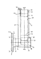
図示の実施例では、固定側ヒンジ部材1は、枢軸ピン2の基端角軸部3を直角に受け入れる肉厚な枢軸ピン固定部4を中央部に形成し、その両側の耳部5に固定枠体6への固着孔7を形成したものである。固定側ヒンジ部材1は、固定孔8を通るボルト9とナット10によって固定枠体6に固着される。本実施例では固定枠体6は貨物トラックの車体であり、回転ウィング体11は車体側面から出入りするステップであり、このステップには運転手や作業員が足を乗せる。
In the illustrated embodiment, the fixed-
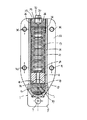
枢軸ピン2の主体部分は回転側ヒンジ部材22の基端筒部39の軸孔37に回転可能に挿通されている。枢軸ピン2の主体部の周面には、90度間隔を置いて3個の着座面13,14,15が枢軸ピン2の長さ方向中心線に対して平行に形成されている。中央の着座面14には回転ウィング体11が閉鎖位置にあるときに押えブロック16の基端面17が圧接するものであり、その両側の着座面13,15には使用態様に応じて回転ウィング体11が開放位置に来たときに押えブロック16の基端面18が圧接する。
The main portion of the
押えブロックの基端面17は押えブロック16の長さ方向中心線に対して直角に形成され、枢軸ピン2の着座面13,14,15と正対して当接するようになっている。押えブロック16の天端面18は押さえブロック16の長さ方向中心線に対して直角に形成され、皿バネ積層体25の最下層の皿バネと正対して当接するようになっている。
着座面13,14、15を形成した枢軸ピン2の周面部分の外側には、O-リング19の収容用環状溝20が形成されている。
The
An
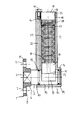
蒲鉾断面状のダンパーハウジング21は、平板状の回転側ヒンジ部材22の片面中央部に一体に突出形成されており、回転側ヒンジ部材22の基端筒部39と交差している。ダンパーハウジング21には、枢軸ピン2の長さ方向中心線に対して直角に配置される空洞部23が形成されている。
回転側ヒンジ部材21とダンパーハウジング22は、回転ウィング体11の適所に設けた取付用凹部40に収容され、回転側ヒンジ部材21の主体部分は、ダンパーハウジング21の両側部位に設けた固着孔36を通る固着具(図示していない)によって、回転ウィング体11に固着される。回転側ヒンジ部材22の基端筒部39は、回転ウィング体11のリブ板部38の位置決め孔12に嵌挿される。
The
The rotation-
押えブロック16と調整部ブロック24と皿バネ積層体25は、空洞部23の長さ方向中心線に沿って収納されている。
円柱状の押えブロック16の外形は、空洞部23の内径に接近して設定され、押えブロック16は空洞部23を軸線方向に摺動する。
The
The outer shape of the
円柱状の調整ブロック24の外周面には、外周ねじ部26が全長にわたって形成されている。空洞部23の先端側に形成した内周ねじ部27の長さは、調整ブロック24の長さよりも長く設定されており、この長さの差異分が調整ブロック24の調整代になっている。調整ブロック24の基端面28には、皿バネ積層体25の最上層の皿バネが当接する。基端面28は調整ブロック24の長さ方向中心線に対して直角に形成され、皿バネ積層体25と正対して当接するようになっている。
調整ブロック24の天端面29の中央部には、回転操作用工具の差込み用六角形凹部30が形成されている。
On the outer peripheral surface of the
A
回転側ヒンジ部材22の端面ねじ孔31には、セットビス32が捻じ込まれており、セットビス32の頭部が調整ブロック24の天端面29の縁部分に係合する。皿バネ積層体25の皿バネは鋼製のものであり、非常に小さな撓みで大きな荷重を受けるものである。皿バネの前記撓みの付与は、調整ブロック24の締め込みによって行なわれ、各皿バネの撓み量の総和として得られる弾性反発力によって、回転ウィング体11に対するダンパー力が得られる。
A
図6は前記ダンパー付きヒンジの取付け状態を示す断面図である。回転ウィング体11は固定枠体6に設けた格納部33に閉鎖位置にあり、ダンパーハウジング21は枢軸ピン2より起立した状態にある。図5と図6に示したように押えブロック16の基端面17は、枢軸ピン2の真ん中の着座面14に当接している。回転ウィング体11は皿バネ積層体25の撓み変形によるダンパー力によって当該閉鎖位置に安定に保持されている。
FIG. 6 is a cross-sectional view showing an attached state of the damper-equipped hinge. The
前記ダンパー力に打ち勝つ力を与えて回転ウィング体11を前記格納部33から開放位置へと引出したとき、枢軸ピン2の着座面14から離れた押えブロック16の基端面17は、図7に示したように90度間隔を置いた別の着座面15に当接し、回転ウィング体11は皿バネ積層体25の撓み変形によるダンパー力によって当該開放位置に安定に保持される。このような着座面14から着座面15、あるいは着座面14から着座面13への当接面の変更動作が滑らかになされるように、着座面13と着座面14の間、そして着座面14とら着座面15の間には、湾曲面部34,35が形成されている。
The
1 固定側ヒンジ部材2 枢軸ピン3 枢軸ピンの基端角軸部4 固定側ヒンジ部材の枢軸ピン固定部5 固定側ヒンジ部材の耳部6 固定枠体7 固定側ヒンジ部材の固着孔8 固定枠体の固定孔9 ボルト10 ナット11 回転ウィング体12 回転ウィング体側の位置決め孔13 着座面14 着座面15 着座面16 押えブロック17 押えブロックの基端面18 押えブロックの天端面
19 O-リング
20 O-リングの収容用環状溝
21 ダンパーハウジング
22 回転側ヒンジ部材
23 ダンパーハウジングの空洞部
24 調整部ブロック
25 皿バネ積層体
26 調整ブロックの外周ねじ部
27 空洞部の内周ねじ部
28 調整ブロックの基端面
29 調整ブロックの天端面
30 回転操作用工具の差込み用凹部
31 回転側ヒンジ部材の端面ねじ孔
32 セットビス
33 固定枠体側の格納部34 湾曲面部35 湾曲面部36 回転側ヒンジ部材の固着孔37 回転側ヒンジ部材の軸孔38 回転ウィング体のリブ板部39 回転側ヒンジ部材の基端筒部40 回転側ヒンジ部材の取付用凹部
DESCRIPTION OF SYMBOLS 1 Fixed side hinge member 2 Pivot pin 3 Base end angle shaft part 4 of fixed axis pin Pivot pin fixed part 5 of fixed side hinge member Ear part 6 of fixed side hinge member Fixed frame body 7 Fixing hole 8 of fixed side hinge member Fixed frame Fixing hole 9 Bolt 10 Nut 11 Rotating wing body 12 Positioning hole 13 on the rotating wing body side Seating surface 14 Seating surface 15 Seating surface 16 Presser block 17 Presser block base end surface 18 Presser block top end surface 19 O-ring 20 O- Ring housing ring groove 21 Damper housing 22 Rotating hinge member 23 Damper housing cavity 24 Adjustment section block 25 Belleville spring stack 26 Adjustment block outer peripheral thread section 27 Hollow section inner peripheral thread section 28 Adjustment block base end face 29 Top end face 30 of the adjustment block Recessed part 31 for inserting the tool for rotation operation End face screw hole 32 of the rotation side hinge member Set screw 3 The storage portion 34 on the fixed frame body side The curved surface portion 35 The curved surface portion 36 The fixing hole 37 of the rotation side hinge member The shaft hole 38 of the rotation side hinge member The rib plate portion 39 of the rotation side wing member The proximal end tubular portion 40 of the rotation side hinge member The rotation side hinge Recess for mounting parts
Claims (1)
前記固定側ヒンジ部材と前記回転側ヒンジ部材の一方に前記枢軸ピンを固定し、前記固定側ヒンジ部材と前記回転側ヒンジ部材の他方にダンパーハウジングを形成し、前記ダンパーハウジングの長さ方向中心線を前記枢軸ピンの長さ方向中心線に対して直角に配置し、前記ダンパーハウジングの長さ方向中心線に沿って皿バネ積層体を収納し、前記枢軸ピンの周側面に前記枢軸ピンの長さ方向中心線に対して平行に配置された着座面を複数個形成し、前記着座面相互の間に前記回転ウィング体の閉鎖位置と開放位置に対応した角度間隔を設定し、
前記ダンパーハウジングの基端部内に長さ方向に摺動可能に押えブロックを収納し、前記押えブロックの基端面を前記枢軸ピンの前記着座面に当接させ、前記押えブロックの天端面を前記皿バネ積層体の最下層の皿バネに当接させ、前記ダンパーハウジングの先端部内に長さ方向に摺動可能に調整ブロックを収納し、前記調整ブロックの基端面を前記皿バネ積層体の最上層の皿バネに当接させ、
前記ダンパーハウジングの内周ねじ部に前記調整ブロックの外周ねじ部を螺合させ、前記調整ブロックのねじ運動によって前記調整ブロックと前記押えブロック間にの前記皿バネ積層体の圧縮負荷を調整するようにしたダンパー付きヒンジ。 A fixed-side hinge member fixed to the fixed frame body, a rotation-side hinge member fixed to the rotating wing body, and a pivot pin that rotatably connects the rotation-side hinge member to the fixed-side hinge member;
The pivot pin is fixed to one of the fixed-side hinge member and the rotary-side hinge member, a damper housing is formed on the other of the fixed-side hinge member and the rotary-side hinge member, and a longitudinal center line of the damper housing Is disposed at right angles to the longitudinal center line of the pivot pin, the disc spring laminated body is accommodated along the longitudinal center line of the damper housing, and the length of the pivot pin is arranged on the peripheral side surface of the pivot pin. Forming a plurality of seating surfaces arranged parallel to the center line in the longitudinal direction, setting an angular interval between the seating surfaces corresponding to the closed position and the open position of the rotating wing body;
A presser block is housed in the base end portion of the damper housing so as to be slidable in the length direction, the base end surface of the presser block is brought into contact with the seating surface of the pivot pin, and the top end surface of the presser block is placed on the plate. An adjustment block is accommodated in the front end portion of the damper housing so as to be slidable in the length direction, and is brought into contact with a lowermost disc spring of the spring laminated body, and a base end surface of the adjustment block is set as an uppermost layer of the disc spring laminated body Abutting against the disc spring,
The outer peripheral screw portion of the adjustment block is screwed into the inner peripheral screw portion of the damper housing, and the compression load of the disc spring laminated body between the adjustment block and the presser block is adjusted by the screw motion of the adjustment block. A hinge with a damper.
Priority Applications (1)
| Application Number | Priority Date | Filing Date | Title |
|---|---|---|---|
| JP2008248262A JP4812820B2 (en) | 2008-09-26 | 2008-09-26 | Hinge with damper |
Applications Claiming Priority (1)
| Application Number | Priority Date | Filing Date | Title |
|---|---|---|---|
| JP2008248262A JP4812820B2 (en) | 2008-09-26 | 2008-09-26 | Hinge with damper |
Publications (2)
| Publication Number | Publication Date |
|---|---|
| JP2010077708A true JP2010077708A (en) | 2010-04-08 |
| JP4812820B2 JP4812820B2 (en) | 2011-11-09 |
Family
ID=42208429
Family Applications (1)
| Application Number | Title | Priority Date | Filing Date |
|---|---|---|---|
| JP2008248262A Expired - Fee Related JP4812820B2 (en) | 2008-09-26 | 2008-09-26 | Hinge with damper |
Country Status (1)
| Country | Link |
|---|---|
| JP (1) | JP4812820B2 (en) |
Cited By (1)
| Publication number | Priority date | Publication date | Assignee | Title |
|---|---|---|---|---|
| GB2484527B (en) * | 2010-10-14 | 2015-05-20 | Chung Chow | Hinge having self centering means |
Citations (5)
| Publication number | Priority date | Publication date | Assignee | Title |
|---|---|---|---|---|
| GB396889A (en) * | 1932-05-11 | 1933-08-17 | James Garth Mitchell | Improvements relating to hinges |
| JPH1046902A (en) * | 1996-05-14 | 1998-02-17 | Ed Scharwaechter Gmbh & Co Kg | Door fixing tool structurally associated with door hinge capable of hooking and removing |
| JP2000110435A (en) * | 1998-10-07 | 2000-04-18 | Sando Kogyosho:Kk | Uneven braking device |
| WO2007125524A1 (en) * | 2006-05-03 | 2007-11-08 | Gosio, Dianora | Hinge structure for self-closing doors or the like, particularly glass doors or the like, and assembly incorporating such structure |
| JP2007308980A (en) * | 2006-05-18 | 2007-11-29 | Suncall Corp | Hinge structure |
-
2008
- 2008-09-26 JP JP2008248262A patent/JP4812820B2/en not_active Expired - Fee Related
Patent Citations (5)
| Publication number | Priority date | Publication date | Assignee | Title |
|---|---|---|---|---|
| GB396889A (en) * | 1932-05-11 | 1933-08-17 | James Garth Mitchell | Improvements relating to hinges |
| JPH1046902A (en) * | 1996-05-14 | 1998-02-17 | Ed Scharwaechter Gmbh & Co Kg | Door fixing tool structurally associated with door hinge capable of hooking and removing |
| JP2000110435A (en) * | 1998-10-07 | 2000-04-18 | Sando Kogyosho:Kk | Uneven braking device |
| WO2007125524A1 (en) * | 2006-05-03 | 2007-11-08 | Gosio, Dianora | Hinge structure for self-closing doors or the like, particularly glass doors or the like, and assembly incorporating such structure |
| JP2007308980A (en) * | 2006-05-18 | 2007-11-29 | Suncall Corp | Hinge structure |
Cited By (1)
| Publication number | Priority date | Publication date | Assignee | Title |
|---|---|---|---|---|
| GB2484527B (en) * | 2010-10-14 | 2015-05-20 | Chung Chow | Hinge having self centering means |
Also Published As
| Publication number | Publication date |
|---|---|
| JP4812820B2 (en) | 2011-11-09 |
Similar Documents
| Publication | Publication Date | Title |
|---|---|---|
| US7805810B2 (en) | Multi leaf extendable gear hinge | |
| US7552509B2 (en) | Hinge buffer device | |
| US8555465B2 (en) | Detent hinge | |
| CN101748946B (en) | Hinge for doors or windows | |
| US7934860B2 (en) | Lighting fixture with angle adjustment arrangement | |
| EP2808473B1 (en) | Stepped door stop | |
| WO2015000251A1 (en) | Camera fastening device | |
| US20060225248A1 (en) | Torque adjusting type hinge | |
| JP5607657B2 (en) | Pivot socket having cartridge bearing and vehicle steering link mechanism having the same | |
| US11319741B2 (en) | Hydraulically damped actuator | |
| US8757564B2 (en) | Angle-adjustable mounting apparatus | |
| ITPD20100065A1 (en) | SUPPORT HEAD FOR OPTICAL OR VIDEO-PHOTOGRAPHIC EQUIPMENT | |
| JP4812820B2 (en) | Hinge with damper | |
| US20100244462A1 (en) | Compression closure | |
| US20070163401A1 (en) | Angle retaining assembly of a hand tool | |
| US8282143B2 (en) | Positioning device | |
| CN109072654A (en) | Door closer device | |
| CN100360760C (en) | Door hinge with concealed bearing | |
| JP2008038459A (en) | Folding door center hinge | |
| JP4006526B2 (en) | Joining device | |
| US20130219678A1 (en) | Clamping And Sliding Device For Polygonal Shaft | |
| CN114991607A (en) | Easy dismouting, atress are deviate from door-hinge system and adopt its on-vehicle refrigerator | |
| JP6501301B2 (en) | Torque hinge and various devices equipped with the same | |
| JP2007056515A (en) | Biaxial hinge device | |
| JP2018100543A (en) | Hinge assembly |
Legal Events
| Date | Code | Title | Description |
|---|---|---|---|
| A131 | Notification of reasons for refusal |
Free format text: JAPANESE INTERMEDIATE CODE: A131 Effective date: 20110411 |
|
| A521 | Request for written amendment filed |
Free format text: JAPANESE INTERMEDIATE CODE: A523 Effective date: 20110412 |
|
| TRDD | Decision of grant or rejection written | ||
| A01 | Written decision to grant a patent or to grant a registration (utility model) |
Free format text: JAPANESE INTERMEDIATE CODE: A01 Effective date: 20110823 |
|
| A01 | Written decision to grant a patent or to grant a registration (utility model) |
Free format text: JAPANESE INTERMEDIATE CODE: A01 |
|
| A61 | First payment of annual fees (during grant procedure) |
Free format text: JAPANESE INTERMEDIATE CODE: A61 Effective date: 20110823 |
|
| R150 | Certificate of patent or registration of utility model |
Ref document number: 4812820 Country of ref document: JP Free format text: JAPANESE INTERMEDIATE CODE: R150 Free format text: JAPANESE INTERMEDIATE CODE: R150 |
|
| FPAY | Renewal fee payment (event date is renewal date of database) |
Free format text: PAYMENT UNTIL: 20140902 Year of fee payment: 3 |
|
| LAPS | Cancellation because of no payment of annual fees |