JP2010076769A - Cooling plate used for cooling device for bag packaging machine, bag packaging machine with the cooling device with the cooling plate, and packaging bag manufactured using the bag packaging machine - Google Patents
Cooling plate used for cooling device for bag packaging machine, bag packaging machine with the cooling device with the cooling plate, and packaging bag manufactured using the bag packaging machine Download PDFInfo
- Publication number
- JP2010076769A JP2010076769A JP2008243822A JP2008243822A JP2010076769A JP 2010076769 A JP2010076769 A JP 2010076769A JP 2008243822 A JP2008243822 A JP 2008243822A JP 2008243822 A JP2008243822 A JP 2008243822A JP 2010076769 A JP2010076769 A JP 2010076769A
- Authority
- JP
- Japan
- Prior art keywords
- cooling
- bag
- heat
- bag mouth
- pair
- Prior art date
- Legal status (The legal status is an assumption and is not a legal conclusion. Google has not performed a legal analysis and makes no representation as to the accuracy of the status listed.)
- Granted
Links
- 238000001816 cooling Methods 0.000 title claims abstract description 116
- 238000004806 packaging method and process Methods 0.000 title claims abstract description 30
- 238000007789 sealing Methods 0.000 claims abstract description 38
- 238000003825 pressing Methods 0.000 claims description 20
- 239000002184 metal Substances 0.000 claims description 10
- 230000037303 wrinkles Effects 0.000 abstract description 10
- 239000006260 foam Substances 0.000 abstract description 4
- 238000007689 inspection Methods 0.000 abstract description 2
- 239000013065 commercial product Substances 0.000 abstract 1
- 238000000034 method Methods 0.000 description 13
- 238000005187 foaming Methods 0.000 description 6
- 238000004049 embossing Methods 0.000 description 4
- 238000004519 manufacturing process Methods 0.000 description 2
- 241000252254 Catostomidae Species 0.000 description 1
- 230000002411 adverse Effects 0.000 description 1
- 239000000498 cooling water Substances 0.000 description 1
- 230000002950 deficient Effects 0.000 description 1
- 230000000694 effects Effects 0.000 description 1
- 239000004744 fabric Substances 0.000 description 1
- 239000011521 glass Substances 0.000 description 1
- 238000010438 heat treatment Methods 0.000 description 1
- 238000007731 hot pressing Methods 0.000 description 1
- 230000001771 impaired effect Effects 0.000 description 1
- 239000007788 liquid Substances 0.000 description 1
- 239000011344 liquid material Substances 0.000 description 1
- 239000000463 material Substances 0.000 description 1
- 239000000203 mixture Substances 0.000 description 1
- 238000012856 packing Methods 0.000 description 1
- 230000000737 periodic effect Effects 0.000 description 1
- 239000007787 solid Substances 0.000 description 1
Images


Landscapes
- Package Closures (AREA)
Abstract
Description
本願発明は、袋詰め包装機における冷却装置に使用する冷却板に関し、さらに詳細に言えば、被包装物が充填された袋の袋口を一対の熱板を備えた熱シール装置でシールし、その後にシールされた袋口を冷却する冷却装置に使用する冷却板に関する。さらに本発明は、該冷却板を使用した冷却装置を備えた袋詰め包装機、及び該袋詰め包装機で製造される包装袋に関する。 The present invention relates to a cooling plate used for a cooling device in a bagging and packaging machine, and more specifically, sealing a bag mouth of a bag filled with an article to be packaged with a heat sealing device including a pair of hot plates, It is related with the cooling plate used for the cooling device which cools the bag mouth sealed after that. Furthermore, the present invention relates to a bag filling and packaging machine provided with a cooling device using the cooling plate, and a packaging bag manufactured by the bag filling and packaging machine.
一対の熱板を用いて袋口をシールする袋詰め包装機においては、一次シール装置、二次シール装置、シール部冷却装置が搭載され、これら装置によって被包装物が充填された袋の袋口を順次シール処理及び冷却処理を施すのが一般的である。一次シール装置及び二次シール装置はそれぞれ一対の熱板を備え、該熱板の互いに対向する挟圧面で袋のシール部を挟圧して熱シールし、その後、冷却装置の一対の冷却板の互いに対向する挟圧面でシール部を挟圧してシール部を冷却する。 In a bag filling and packaging machine that seals a bag mouth using a pair of hot plates, a primary seal device, a secondary seal device, and a seal portion cooling device are mounted, and the bag mouth of the bag filled with an article to be packaged by these devices Generally, a sealing process and a cooling process are sequentially performed. Each of the primary sealing device and the secondary sealing device includes a pair of hot plates, and heat seals are performed by pressing the seal portion of the bag between the hot pressing surfaces of the hot plates facing each other. The sealing portion is clamped by the opposing clamping surface to cool the sealing portion.
ところで、熱板による熱シールを行うと、袋口表面にシワが発生したり、被包装物たる液状物が袋口に付着していた場合所謂噛み込みがあった場合には発泡が生じ、包装製品の美観が損なわれる。これに対応するために、冷却板の挟圧面に細かな凹凸が形成されたシート、例えばフッ素樹脂を含浸したガラスクロスなどのシートを掛け、このシート表面の凹凸を利用して袋口のシール部に例えば網目状の模様を形成してシワや発泡を目立たなくする処理などが行われている。しかしこのシートは使用するにつれて摩滅しその凹凸が消滅してしまう。従って定期的に冷却後の袋口のシール部を検査し、必要あればシートを交換する必要があった。また、袋口のシール部に形成される模様はシワや発泡を目立たなくすることを目的としているので、模様としては網目、筋目、梨地、ディンプル等が採用されており、これらの模様は意匠性に乏しく、商品価値を高めるには至っていない。 By the way, when heat sealing is performed by a hot plate, foaming occurs when wrinkles occur on the bag mouth surface, or when a liquid material as a package is attached to the bag mouth, so-called biting occurs, and packaging The appearance of the product is impaired. In order to cope with this, a sheet with fine irregularities formed on the clamping surface of the cooling plate, such as a glass cloth impregnated with a fluororesin, is hung, and the sealing portion of the bag mouth is utilized using the irregularities on the surface of the sheet. For example, a mesh pattern is formed to make wrinkles and foam inconspicuous. However, as this sheet is used, it becomes worn and the irregularities disappear. Accordingly, it is necessary to periodically inspect the sealing portion of the bag mouth after cooling and replace the sheet if necessary. In addition, the pattern formed on the seal part of the bag mouth is intended to make wrinkles and foam inconspicuous, so the pattern is mesh, streaks, satin, dimples, etc. The product value has not been improved.
特公平1−32105号、特公平6−49492号、特開2004−136940号では、熱板の挟圧面に凹凸部を形成し、この挟圧面で袋口を直接挟圧することにより袋口に所定の網目、筋目、梨地、ディンプルなどの模様のエンボス処理を行っている。しかし熱板には熱による反りが生じて挟圧面が平らではないので、挟圧面に凹凸を形成した上記公報記載の熱板を使用した熱シール装置では、袋口にシワや発泡が顕著に生じて冷却板に掛けたシートでは処理しきれないような状態となり、逆に包装製品の美観が損なわれてしまう。また、凹凸の存在により、袋口への熱の伝達が不均一となり、シール不良が生じてしまう場合もある。 In Japanese Patent Publication No. 1-32105, Japanese Patent Publication No. 6-49492, and Japanese Patent Application Laid-Open No. 2004-136940, a concave and convex portion is formed on the pinching surface of the hot plate, and the bag mouth is directly pinched by this pinching surface, so that the bag mouth is predetermined. Embossing of patterns such as mesh, streaks, satin and dimples. However, since the hot plate is warped by heat and the pressing surface is not flat, in the heat sealing device using the hot plate described in the above publication in which irregularities are formed on the pressing surface, wrinkles and foaming are noticeably generated at the bag mouth. Thus, the sheet placed on the cooling plate cannot be processed, and the aesthetics of the packaged product are adversely affected. In addition, due to the presence of the irregularities, the heat transfer to the bag mouth becomes non-uniform, which may cause a seal failure.
特開2004−268933号では、片側の冷却板の挟圧面に凹部を形成し、この凹部によりシール部の片面のみにマークを形成することが開示されている。しかし、このマークは使用されたシールヘッドを特定するために使用するものであり、熱シールによって袋口シール部に生じたシワや発泡を目立たなくすることはできない。 Japanese Patent Application Laid-Open No. 2004-268933 discloses that a concave portion is formed on the pressing surface of the cooling plate on one side, and a mark is formed only on one side of the seal portion by this concave portion. However, this mark is used to specify the used seal head, and it is impossible to make the wrinkles and foaming generated in the bag mouth seal portion inconspicuous by heat sealing.
特開2000−264346号では、袋のシール部に模様があるが、これは印刷されたものである。
特開2004−142132号では袋表面にエンボス処理を施しているが、このエンボスは、袋を製造する前のシート材を下部材で受けて加熱した上部材で加熱して形成したり、袋の袋口から下部材を袋内へ挿入して外側に上部材を当てて形成している。従って袋口を熱シールした際に生じるシワや発泡には対応できない。
In Japanese Patent Application Laid-Open No. 2004-142132, the bag surface is embossed, and this embossing is formed by heating the upper member that receives and heats the sheet material before manufacturing the bag with the lower member, The lower member is inserted into the bag through the bag mouth and the upper member is applied to the outside. Therefore, it cannot cope with wrinkles and foaming generated when the bag mouth is heat-sealed.
本願発明は上記従来例の問題点に鑑みなされたものであり、熱シールによって袋口シール部に生じるシワや発泡を目立たなくすることができ、従来のような定期的な袋口シール部の検査、シートの交換等が不要で、さらにシール不良も生ぜず、袋の美観性を高めて商品価値を高めることのできる冷却板を提供することを目的とする。 The present invention has been made in view of the above-mentioned problems of the conventional example, and it is possible to make the wrinkles and foam generated in the bag mouth seal portion inconspicuous by heat sealing, and the conventional periodic inspection of the bag mouth seal portion. It is an object of the present invention to provide a cooling plate that does not require replacement of a sheet or the like, does not cause a sealing failure, and can enhance the aesthetics of the bag and increase the product value.
上記課題を解決するために本願発明においては、袋へ被包装物を充填し、袋口の熱シールを行う袋詰め包装機に備えられ、熱シール後に熱シールされた袋口を冷却する冷却装置に使用される冷却板を金属製とし、袋口を冷却する際に袋口に押圧される挟圧面に一定のパターンで繰り返される複数の文字又は記号を凸状又は凹状に形成した。
その冷却板は、挟圧面を備えた挟圧部材と該挟圧部材を支持する支持部材とで構成し、挟圧部材は支持部材に対して着脱自在に取付けられるようにすることにより、挟圧部材の交換のみで仕様の異なる袋に対応することができ、作業能率を向上できる。
本発明はさらに、袋へ被包装物を充填し、袋口の熱シールを行う袋詰め包装機に備えられ、熱シール後に袋口を冷却する冷却装置に使用される一対の冷却板を提供し、その一対のうちの一方の冷却板は金属製とし、袋口を冷却する際に袋口に押圧される挟圧面に一定のパターンで繰り返される複数の文字又は記号を凸状又は凹状に形成した。
一対の冷却板のうちの他方の冷却板は金属製で、袋口を冷却する際に袋口に押圧される挟圧面は平坦面に形成し、或いはその挟圧面には網目状の凹凸を形成することができる。
本発明はさらに、袋へ被包装物を充填し、袋口の熱シールを行う袋詰め包装機に備えられ、熱シール後に袋口を冷却する冷却装置に使用される一対の冷却板を提供し、その冷却板は金属製とし、袋口を冷却する際に熱シールされた袋口に押圧されるそれぞれの挟圧面に網目状に凸部が形成されている。そしてその凸部は、截頭四角錐状に形成することができる。
本願発明はさらに、上記一対の冷却板を使用した冷却装置を備えた袋詰め装置を提供し、この冷却板の押圧面は袋に直接押圧される。
本願発明はさらに、被包装物が充填され、袋口が熱シールされ、該熱シールされたシール部にはエンボス処理が施された包装袋を提供し、その包装袋は前述した冷却装置を備えた袋詰め包装機で製造されている
In order to solve the above-mentioned problems, in the present invention, a cooling device is provided in a bag filling and packaging machine that fills a bag with an object to be packaged and heat-seals the bag mouth, and cools the heat-sealed bag mouth after heat sealing. The cooling plate used in the above was made of metal, and a plurality of letters or symbols repeated in a certain pattern were formed in a convex shape or a concave shape on the pressing surface pressed against the bag mouth when the bag mouth was cooled.
The cooling plate is composed of a clamping member having a clamping surface and a supporting member that supports the clamping member, and the clamping member is detachably attached to the supporting member. It is possible to deal with bags having different specifications only by exchanging members, and work efficiency can be improved.
The present invention further provides a pair of cooling plates used in a bagging and packaging machine that fills a bag with an article to be packaged and heat-seals the bag mouth, and is used in a cooling device that cools the bag mouth after heat-sealing. One cooling plate of the pair is made of metal, and a plurality of letters or symbols repeated in a certain pattern are formed in a convex shape or a concave shape on the clamping surface pressed against the bag mouth when the bag mouth is cooled. .
The other cooling plate of the pair of cooling plates is made of metal, and the pressing surface pressed against the bag mouth when the bag mouth is cooled is formed into a flat surface, or a mesh-like unevenness is formed on the pressing surface. can do.
The present invention further provides a pair of cooling plates used in a bagging and packaging machine that fills a bag with an article to be packaged and heat-seals the bag mouth, and is used in a cooling device that cools the bag mouth after heat-sealing. The cooling plate is made of metal, and a convex portion is formed in a mesh shape on each clamping surface that is pressed by the heat-sealed bag mouth when the bag mouth is cooled. And the convex part can be formed in a truncated quadrangular pyramid shape.
The present invention further provides a bagging device provided with a cooling device using the pair of cooling plates, and the pressing surface of the cooling plate is directly pressed against the bag.
The present invention further provides a packaging bag that is filled with an article to be packaged, the bag mouth is heat-sealed, and the heat-sealed seal portion is embossed, and the packaging bag includes the cooling device described above. Manufactured by a bag filling and packaging machine
本発明によれば、熱シールされた袋口部分には挟圧部材の挟圧面に形成された文字、符号に対応した文字或いは網目状に形成された凸部が転写されて凹状或いは凸状に形成される。これにより前の工程での熱シールにより袋口に生じたシワや発泡を目立たなくすることができる。また、このエンボス処理を熱シール処理工程においてではなく冷却工程で行うので、平坦な挟圧面を備えた熱板を使用して熱シールを行えるので、良好な熱シールを行うことができる。また、従来のようなシートを使用しないので、袋口シール部の定期的な検査やシートの交換が不要となり作業効率が高まる。また、挟圧面に形成する文字、符号などを一定のパターンで繰り返し形成することにより、従来に比して包装製品の美観を高めることが可能となる。また、文字、符号などとして例えばその商品の商標を表すことも可能であり、好都合である。 According to the present invention, a character formed on the pinching surface of the pinching member, a character corresponding to the code, or a convex portion formed in a mesh shape is transferred to the heat sealed bag mouth portion to form a concave shape or a convex shape. It is formed. Thereby, wrinkles and foaming generated in the bag mouth by heat sealing in the previous step can be made inconspicuous. In addition, since the embossing process is performed in the cooling process, not in the heat sealing process, heat sealing can be performed using a hot plate having a flat clamping surface, so that good heat sealing can be performed. In addition, since a conventional sheet is not used, it is not necessary to periodically inspect the bag mouth seal portion and replace the sheet, thereby increasing work efficiency. Further, by repeatedly forming characters, symbols, and the like formed on the clamping surface in a certain pattern, it is possible to enhance the aesthetics of the packaged product as compared with the conventional case. Moreover, it is possible to express the trademark of the product as characters, symbols, etc., which is convenient.
以下図面を参照して本発明の実施の形態について説明するが、以下の実施の形態は例示的に示すものであり、本願発明の範囲がそれに限定されるものではない。 Embodiments of the present invention will be described below with reference to the drawings. However, the following embodiments are exemplarily shown, and the scope of the present invention is not limited thereto.
図1は本発明の実施の形態に係る袋詰め包装機(以下、「包装機」という)1の全体の構成を示す全体構成斜視図である。この実施の形態では包装機1は回転テーブル3を備えたロータリー式である。回転テーブル3には、対になって袋Bの両側縁部を挟持して保持するグリッパ5が円周方向所定の間隔で設けられ、回転テーブル3の間欠回転に伴ってステーション即ち停止位置S1からS10へと順次移動する。このステーションS1からS10において、回転テーブル3が停止中に各種の処理工程が実行される。なお、本実施の形態では回転テーブル3は間欠回転としたが、連続回転式でもよい。
FIG. 1 is an overall configuration perspective view showing an overall configuration of a bag filling and packaging machine (hereinafter referred to as “packaging machine”) 1 according to an embodiment of the present invention. In this embodiment, the packaging machine 1 is a rotary type provided with a rotary table 3. The rotary table 3 is provided with
最初のステーションS1は給袋工程であり、本実施の形態ではコンベアマガジンとされた袋マガジン7によって一枚ずつ繰出される袋Bを一対の袋取出し吸盤9で取出し、グリッパ5へ向けて移送しながらその姿勢を垂直状態に変更し、それをグリッパ5が受け取って保持する。コンベアマガジン7の構成及びそれから袋取出し吸盤9を用いて袋Bをグリッパ5に引渡す構成は公知なのでその詳細な説明は省略する。次のステーションS2は印刷工程であり、プリンタ11によって袋Bに製造日等を印刷する。ステーションS3は開袋工程で、一対の開口吸盤13及び開口ガイド15とで袋Bの口を開く。開口ガイド15は追従型であり、袋Bに追従してステーション4へ移動し、所定のタイミングでステーション3へ戻る。ステーションS4は固形の被包装物をホッパ17を用いて袋Bに充填する工程、ステーションS5は図示しないタンクに貯留された液状の被包装物をノズル19を介して充填する工程である。
The first station S1 is a bag supply process. In this embodiment, the bags B fed one by one by the bag magazine 7 which is a conveyor magazine are taken out by a pair of bag take-out
次にステーションS6はスチームノズル21からスチームを袋内へ噴射して袋B内の空気をスチームで置換して脱気する工程である。ステーションS7には一対の熱板23を備えた一次シール装置22が配置されている。熱板23にはそれぞれ内部に棒状のヒータ(図示せず)が配置され、熱板23を所定の温度に加熱する。そして熱板23の互いに対向する挟圧面で袋Bの袋口縁部から所定の範囲に渡って熱シールを施す。ステーションS8にはやはり一対の熱板25を備えた二次シール装置24が配置され、二次シールを施す。ステーションS9には一対の冷却板28、38を備えた冷却装置27が配置され、袋Bの熱シールを施されたシール部を冷却し、その後製品としての袋Bを製品排出シート26へ排出する。ステーションS10では不良品と判定された袋Bを排出する。
Next, the station S6 is a process in which steam is jetted from the
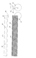
次にステーションS9に配置される冷却装置27について、図2以下を参照して詳細に説明する。図2は冷却装置27の要部を示す側面図である。
Next, the
図において、符号30は上側スライド軸であり、図示しない駆動源に連結されていて軸方向(図2において左右方向)に進退するようになっている。上側スライド軸30の先端には冷却板取付けブロック31が固定して取付けられている。そして冷却板取付けブロック31の下端には冷却板28が固定して取付けられている。
In the figure,
冷却板28は支持部材としての冷却板本体32と、これに支持される挟圧部材33とで構成されている。冷却板本体32は縦断面方形の形をした金属製の細長い部材であり、図において紙面に垂直方向に延びている。挟圧部材33は縦断面が上下逆になった略L字形をした金属製の細長い部材で、図示しないボルト等適宜な取付け手段で、図示のように冷却板本体32に着脱自在に取付けられている。挟圧部材33の左側端面は袋Bに押圧される挟圧面34であり、袋Bのグリッパ5により把持された部分より上側の、前の工程で熱シールを施された袋口に対向し、上側スライド軸30が図中左側へ移動することにより袋口に押圧される。冷却板本体32及び挟圧部材33は袋Bの幅全体に渡って覆うに十分な長さを備えており、冷却板本体32の内部には必要ある場合には冷却水が循環できる流路(図示せず)が形成されており、挟圧部材33を冷却して、冷却装置27による袋Bの冷却効果が十分得られるようになっている。
The cooling
他方の冷却板38及びそれを冷却装置27に取付ける構成は上記一方の冷却板28及びそれを冷却装置27に取付ける構成と略同様である。即ち、符号40は図示しない駆動装置に連結された下側スライド軸、41はその先端に固定して取付けられた冷却板取付けブロックであり、冷却板38は冷却板取付けブロック41の先端に固定して取付けられた冷却板本体42とそれに着脱自在に取付けられた挟圧部材43とで構成されている。そして、挟圧部材43はその挟圧面44が袋Bを挟んで一方の挟圧部材33の挟圧面34に対向するように配置されている。冷却板28,38による袋Bを冷却する動作については公知の冷却装置と同様であるので、その詳細な説明は省略する。
The
図3は前述した一方の冷却板28を構成する挟圧部材33を示す図で、(イ)は平面図、(ロ)は正面図、(ハ)は右側面図である。また、図4は図3(ロ)におけるA部の拡大図、図5は図3(ハ)におけるB部の拡大図である。これらの図に示されるように、挟圧部材33の挟圧面34には、一定のパターンで繰り返される複数の文字又は記号が凸状又は凹状に形成されており、本実施の形態ではアルファベットT、Y、Jの文字が左右反転した状態で凸状に繰り返し形成されている。図3において符号35は、挟圧部材33を熱板本体32に取付けるボルトが挿通される孔である。他方の冷却板38を構成する挟圧部材43の挟圧面44は本実施の形態では何らの凹凸も形成されておらず、平坦な面になっている。本実施の形態ではこのような一対の冷却板28,38を用いて袋Bの熱シールされた袋口を冷却し、その際、従来使用していたシートなどを使用せず、挟圧面34、44は袋Bに直接押圧される。
3A and 3B are views showing the pressing
図6はこのようにして冷却された袋Bを示す正面図であり、図7は図6のC部の拡大図である。上記の熱板28,38を用いた冷却装置27を備えた本実施の形態での袋詰め包装機では、図6,7に示されるように、熱シールされた袋口部分には挟圧部材33の挟圧面34に形成された文字、符号に対応した文字が転写されて凹状に形成される。これにより前の工程での熱シールにより袋口に生じたシワや発泡が目立たなくなる。また、このエンボス処理を冷却工程で行い、熱シール処理においては平坦な挟圧面を備えた熱板を使用して熱シールを行うので、良好な熱シールを行うことができる。また、従来のようなシートを使用しないので、袋口シール部の検査やシートの交換が不要となる。また、挟圧面に形成する文字、符号などを一定のパターンで繰り返し形成することにより、従来に比して包装製品の美観を高めることが可能となる。また、文字、符号などとして例えばその商品の商標を表すことも可能である。
FIG. 6 is a front view showing the bag B thus cooled, and FIG. 7 is an enlarged view of a portion C in FIG. In the bagging and packaging machine according to the present embodiment having the cooling
なお上記実施の形態では一方の挟圧部材33の挟圧面34に形成する文字、符号等は凸状に形成したが、これを凹状としても良い。また他方の挟圧部材43の挟圧面44は平坦ではなく、例えば網目状に凹凸を形成しても良い。
In the above embodiment, the letters, symbols, etc. formed on the pinching
図8乃至10を参照して挟圧部材の他の例について説明する。図8乃至10は第1の実施の形態での図3、4,5にそれぞれ対応する図である。 Another example of the pinching member will be described with reference to FIGS. 8 to 10 correspond to FIGS. 3, 4 and 5 in the first embodiment, respectively.
この挟圧部材53において前述の実施の形態で使用された一方の挟圧板と異なるのは、その挟圧面54に形成されるのが文字、符号ではなく網目状に形成された凸部である点であり、他の構成は同じである。なお、この例では一対の冷却板を構成する2つの冷却板では、それぞれの挟圧部材の挟圧面に同じ形状の凸部が網目状に形成されている。また、この挟圧部材53に組合される冷却板本体、或いはそれが取付けられる冷却板取付けブロック、上側及び下側スライド軸などは先の実施の形態でのそれと同じでよい。
The pinching
この例での挟圧部材53の挟圧面54に網目状に形成される凸部55は、図9、10に示されるように截頭四角錐状に形成されている。この挟圧部材53を使用することにより、袋Bの袋口には、截頭四角錐状の窪みが網目状に形成される。
The
1:袋詰め包装機 3:回転テーブル 5:グリッパ 22:一次シール装置 24:二次シール装置 27:冷却装置 28:冷却板 32:冷却板本体 33:挟圧部材 34:挟圧面 38:冷却板 42:冷却板本体 43:挟圧部材 44:挟圧面 1: Bag filling and packaging machine 3: Rotary table 5: Gripper 22: Primary sealing device 24: Secondary sealing device 27: Cooling device 28: Cooling plate 32: Cooling plate body 33: Clamping member 34: Clamping surface 38: Cooling plate 42: Cooling plate body 43: Clamping member 44: Clamping surface
Claims (10)
Priority Applications (1)
| Application Number | Priority Date | Filing Date | Title |
|---|---|---|---|
| JP2008243822A JP5319222B2 (en) | 2008-09-24 | 2008-09-24 | Bag packing machine |
Applications Claiming Priority (1)
| Application Number | Priority Date | Filing Date | Title |
|---|---|---|---|
| JP2008243822A JP5319222B2 (en) | 2008-09-24 | 2008-09-24 | Bag packing machine |
Publications (2)
| Publication Number | Publication Date |
|---|---|
| JP2010076769A true JP2010076769A (en) | 2010-04-08 |
| JP5319222B2 JP5319222B2 (en) | 2013-10-16 |
Family
ID=42207676
Family Applications (1)
| Application Number | Title | Priority Date | Filing Date |
|---|---|---|---|
| JP2008243822A Active JP5319222B2 (en) | 2008-09-24 | 2008-09-24 | Bag packing machine |
Country Status (1)
| Country | Link |
|---|---|
| JP (1) | JP5319222B2 (en) |
Cited By (5)
| Publication number | Priority date | Publication date | Assignee | Title |
|---|---|---|---|---|
| CN102826257A (en) * | 2012-09-27 | 2012-12-19 | 浙江大学台州研究院 | Sealing device of automatic packaging machine of disposable syringe |
| CN104691846A (en) * | 2015-03-02 | 2015-06-10 | 安徽永成电子机械技术有限公司 | Separating type heat conducting block for multifunctional heat sealer |
| CN108438385A (en) * | 2018-03-28 | 2018-08-24 | 漳州宇杰自动化科技有限公司 | A kind of secondary reshaping device |
| CN111453094A (en) * | 2020-05-09 | 2020-07-28 | 江苏瑞尔光学有限公司 | Lens bag packaging machine |
| CN113581566A (en) * | 2021-06-17 | 2021-11-02 | 泉州智造者机械设备有限公司 | Packaging mechanism for independent small-package baby diaper production line |
Citations (9)
| Publication number | Priority date | Publication date | Assignee | Title |
|---|---|---|---|---|
| JPH02296630A (en) * | 1989-04-28 | 1990-12-07 | Dainippon Printing Co Ltd | Heat sealing device |
| JPH09110002A (en) * | 1995-10-13 | 1997-04-28 | Kamaya Kagaku Kogyo Co Ltd | Sealing method of cylindrical container |
| JPH09188317A (en) * | 1996-01-11 | 1997-07-22 | Yoshino Kogyosho Co Ltd | Tray or partition plate for packaging items and production thereof |
| JPH10119931A (en) * | 1996-10-18 | 1998-05-12 | Fuji Photo Film Co Ltd | Sealing method for packaging bag |
| JPH10151639A (en) * | 1996-11-22 | 1998-06-09 | Sekisui Plastics Co Ltd | Method and apparatus for molding foamed polyethylene terephthalate sheet |
| JP2003237739A (en) * | 2002-02-13 | 2003-08-27 | Toyo Jidoki Co Ltd | Sealing method for packaging bag and filled and sealed packaging bag |
| JP2006044704A (en) * | 2004-08-02 | 2006-02-16 | Dainippon Sumitomo Pharma Co Ltd | Packaging bag, sealing method and device therefor, and bag-making apparatus |
| JP2006298390A (en) * | 2005-04-15 | 2006-11-02 | Orihiro Engineering Co Ltd | Vertical filling and packaging machine and manufacturing method for packaging bag |
| JP2006341437A (en) * | 2005-06-08 | 2006-12-21 | Hanshin Kasei Kogyo Kk | Heat-sealing mold and heat-sealing device |
-
2008
- 2008-09-24 JP JP2008243822A patent/JP5319222B2/en active Active
Patent Citations (9)
| Publication number | Priority date | Publication date | Assignee | Title |
|---|---|---|---|---|
| JPH02296630A (en) * | 1989-04-28 | 1990-12-07 | Dainippon Printing Co Ltd | Heat sealing device |
| JPH09110002A (en) * | 1995-10-13 | 1997-04-28 | Kamaya Kagaku Kogyo Co Ltd | Sealing method of cylindrical container |
| JPH09188317A (en) * | 1996-01-11 | 1997-07-22 | Yoshino Kogyosho Co Ltd | Tray or partition plate for packaging items and production thereof |
| JPH10119931A (en) * | 1996-10-18 | 1998-05-12 | Fuji Photo Film Co Ltd | Sealing method for packaging bag |
| JPH10151639A (en) * | 1996-11-22 | 1998-06-09 | Sekisui Plastics Co Ltd | Method and apparatus for molding foamed polyethylene terephthalate sheet |
| JP2003237739A (en) * | 2002-02-13 | 2003-08-27 | Toyo Jidoki Co Ltd | Sealing method for packaging bag and filled and sealed packaging bag |
| JP2006044704A (en) * | 2004-08-02 | 2006-02-16 | Dainippon Sumitomo Pharma Co Ltd | Packaging bag, sealing method and device therefor, and bag-making apparatus |
| JP2006298390A (en) * | 2005-04-15 | 2006-11-02 | Orihiro Engineering Co Ltd | Vertical filling and packaging machine and manufacturing method for packaging bag |
| JP2006341437A (en) * | 2005-06-08 | 2006-12-21 | Hanshin Kasei Kogyo Kk | Heat-sealing mold and heat-sealing device |
Cited By (7)
| Publication number | Priority date | Publication date | Assignee | Title |
|---|---|---|---|---|
| CN102826257A (en) * | 2012-09-27 | 2012-12-19 | 浙江大学台州研究院 | Sealing device of automatic packaging machine of disposable syringe |
| CN104691846A (en) * | 2015-03-02 | 2015-06-10 | 安徽永成电子机械技术有限公司 | Separating type heat conducting block for multifunctional heat sealer |
| CN108438385A (en) * | 2018-03-28 | 2018-08-24 | 漳州宇杰自动化科技有限公司 | A kind of secondary reshaping device |
| CN108438385B (en) * | 2018-03-28 | 2024-04-09 | 福建宇杰自动化科技有限公司 | Secondary shaping device |
| CN111453094A (en) * | 2020-05-09 | 2020-07-28 | 江苏瑞尔光学有限公司 | Lens bag packaging machine |
| CN113581566A (en) * | 2021-06-17 | 2021-11-02 | 泉州智造者机械设备有限公司 | Packaging mechanism for independent small-package baby diaper production line |
| CN113581566B (en) * | 2021-06-17 | 2023-11-21 | 徐州力达缝纫设备制造有限公司 | Packaging mechanism for independent small-package baby diaper production line |
Also Published As
| Publication number | Publication date |
|---|---|
| JP5319222B2 (en) | 2013-10-16 |
Similar Documents
| Publication | Publication Date | Title |
|---|---|---|
| JP5450996B2 (en) | Vertical bagging and packaging method and apparatus | |
| JP5319222B2 (en) | Bag packing machine | |
| US20160122057A1 (en) | Packaging Machine | |
| EP1228964B1 (en) | Method for manufacturing flexible bags and vertical type forming, filing and sealing machine | |
| US20190344912A1 (en) | Packaging machine | |
| ES2912663T3 (en) | Film packaging as well as method and sealing station for the production of a film packaging | |
| JP5437777B2 (en) | Filling and packaging machine and method for manufacturing packaging container | |
| WO2018066029A1 (en) | Vertical bag-making/filling machine and method for producing content-filled film packaging bag | |
| US9021770B2 (en) | Sealing station | |
| JP2006298390A (en) | Vertical filling and packaging machine and manufacturing method for packaging bag | |
| KR101945321B1 (en) | Sealing device, blister packaging machine, and blister pack manufacturing method | |
| JP6125419B2 (en) | Method and apparatus for manufacturing a bag having a recess for accommodating an article to be packaged on one bag surface | |
| JP6253074B1 (en) | Packaging bag sealing device | |
| JP2020029268A (en) | Seal device | |
| JP2017100774A (en) | Ultrasonic seal method and device | |
| JP2011121621A (en) | Heat-seal packaging device | |
| JP2000218718A (en) | Continuous manufacturing device for bag with check valve | |
| JP3378777B2 (en) | Engraving method of polyethylene bag | |
| JP7056898B2 (en) | Deep drawing packaging machine | |
| JP4625347B2 (en) | Tube device for bag making and packaging machine | |
| JP2020066453A (en) | Seal method and seal device | |
| JP6507349B2 (en) | Gas filling and packaging machine and inert gas filling method in gas filling and packaging machine | |
| JP6168969B2 (en) | Thermal printer device | |
| CN216468893U (en) | Embossing device of sealing machine | |
| CN211139871U (en) | Heating mechanism for sealing machine |
Legal Events
| Date | Code | Title | Description |
|---|---|---|---|
| A621 | Written request for application examination |
Free format text: JAPANESE INTERMEDIATE CODE: A621 Effective date: 20110421 |
|
| A977 | Report on retrieval |
Free format text: JAPANESE INTERMEDIATE CODE: A971007 Effective date: 20121130 |
|
| A131 | Notification of reasons for refusal |
Free format text: JAPANESE INTERMEDIATE CODE: A131 Effective date: 20130108 |
|
| A521 | Request for written amendment filed |
Free format text: JAPANESE INTERMEDIATE CODE: A523 Effective date: 20130130 |
|
| TRDD | Decision of grant or rejection written | ||
| A01 | Written decision to grant a patent or to grant a registration (utility model) |
Free format text: JAPANESE INTERMEDIATE CODE: A01 Effective date: 20130702 |
|
| A61 | First payment of annual fees (during grant procedure) |
Free format text: JAPANESE INTERMEDIATE CODE: A61 Effective date: 20130711 |
|
| R150 | Certificate of patent or registration of utility model |
Ref document number: 5319222 Country of ref document: JP Free format text: JAPANESE INTERMEDIATE CODE: R150 Free format text: JAPANESE INTERMEDIATE CODE: R150 |
|
| R250 | Receipt of annual fees |
Free format text: JAPANESE INTERMEDIATE CODE: R250 |
|
| R250 | Receipt of annual fees |
Free format text: JAPANESE INTERMEDIATE CODE: R250 |
|
| R250 | Receipt of annual fees |
Free format text: JAPANESE INTERMEDIATE CODE: R250 |
|
| R250 | Receipt of annual fees |
Free format text: JAPANESE INTERMEDIATE CODE: R250 |
|
| R250 | Receipt of annual fees |
Free format text: JAPANESE INTERMEDIATE CODE: R250 |
|
| R250 | Receipt of annual fees |
Free format text: JAPANESE INTERMEDIATE CODE: R250 |
|
| R250 | Receipt of annual fees |
Free format text: JAPANESE INTERMEDIATE CODE: R250 |
|
| R250 | Receipt of annual fees |
Free format text: JAPANESE INTERMEDIATE CODE: R250 |
|
| R250 | Receipt of annual fees |
Free format text: JAPANESE INTERMEDIATE CODE: R250 |