JP2010076538A - Battery arrangement structure of motorcycle - Google Patents
Battery arrangement structure of motorcycle Download PDFInfo
- Publication number
- JP2010076538A JP2010076538A JP2008245634A JP2008245634A JP2010076538A JP 2010076538 A JP2010076538 A JP 2010076538A JP 2008245634 A JP2008245634 A JP 2008245634A JP 2008245634 A JP2008245634 A JP 2008245634A JP 2010076538 A JP2010076538 A JP 2010076538A
- Authority
- JP
- Japan
- Prior art keywords
- battery
- storage box
- arrangement structure
- motorcycle
- storage
- Prior art date
- Legal status (The legal status is an assumption and is not a legal conclusion. Google has not performed a legal analysis and makes no representation as to the accuracy of the status listed.)
- Granted
Links
Images


Abstract
Description
本発明は、自動二輪車のバッテリ配置構造に関する。 The present invention relates to a battery arrangement structure for a motorcycle.
自動二輪車には、ヘッドパイプから後ろ下がりに延びるメインフレームと、メインフレームの後部に連接されて後ろ上がりに延びる左右一対のリヤフレームと、左右一対のリヤフレーム上に配置され、両リヤフレーム間に膨出する収納ボックスと、この収納ボックスに設けられ、バッテリの少なくとも一部を収納ボックス内に突出させて収納するバッテリ収納凹部とを備えるものがある(例えば、特許文献1参照)
しかし、従来の構成では、左右一対のリヤフレーム間に収納ボックス内のバッテリが位置するため、このバッテリがある部分にはリヤフレーム間を繋ぐクロスフレームを設けることができず、クロスフレームのレイアウトが制約される問題があった。 However, in the conventional configuration, since the battery in the storage box is located between the pair of left and right rear frames, a cross frame that connects the rear frames cannot be provided in a portion where the battery is present, and the layout of the cross frame is There was a constrained problem.
本発明は、上述した事情を鑑みてなされたものであり、リヤフレーム間を繋ぐクロスフレームのレイアウト自由度を向上することができる自動二輪車のバッテリ配置構造を提供することを目的としている。 The present invention has been made in view of the above-described circumstances, and an object of the present invention is to provide a battery arrangement structure for a motorcycle that can improve the layout freedom of a cross frame that connects rear frames.
上述課題を解決するため、本発明は、ヘッドパイプから後ろ下がりに延びるメインフレームと、メインフレームの後部に連接されて後ろ上がりに延びる左右一対のリヤフレームと、メインフレーム上又は左右一対のリヤフレーム上に配置され、両リヤフレーム間に一部が膨出する収納ボックスと、この収納ボックスに設けられ、バッテリの少なくとも一部を収納ボックス内に突出させてバッテリを支持するバッテリ収納部とを備える自動二輪車のバッテリ配置構造において、前記バッテリとこのバッテリを収納するバッテリ収納部とを、車両側面視で、前記リヤフレームの上方に配置したことを特徴とする。
この発明によれば、バッテリとこのバッテリを収納するバッテリ収納部とを、車両側面視でリヤフレームの上方に配置したので、バッテリおよびバッテリ収納部をリヤフレーム間から外すことができ、リヤフレーム間をつなぐクロスフレームを設ける際、このクロスフレームのレイアウト自由度を向上することができる。
In order to solve the above-described problems, the present invention provides a main frame extending rearward and downward from the head pipe, a pair of left and right rear frames connected to the rear portion of the main frame and extending rearward, and a pair of left and right rear frames on the main frame. A storage box that is disposed above and partially bulges between the rear frames, and a battery storage unit that is provided in the storage box and supports the battery by projecting at least a part of the battery into the storage box. In the battery arrangement structure for a motorcycle, the battery and a battery storage portion for storing the battery are arranged above the rear frame in a side view of the vehicle.
According to the present invention, since the battery and the battery storage portion for storing the battery are disposed above the rear frame in a side view of the vehicle, the battery and the battery storage portion can be removed from between the rear frames. When the cross frame connecting the two is provided, the layout freedom of the cross frame can be improved.
上記構成において、前記バッテリは、車両側面視で、後ろ上がりに延びる前記リヤフレームの傾斜に沿うように傾斜して設けられ、傾斜した状態でその一部が前記収納ボックス内に突出するようにしてもよい。この構成によれば、バッテリをリヤフレームに近接して配置することが可能になり、バッテリをリヤフレーム寄りに配置できる分だけ、バッテリの収納ボックス内への突出量を減らして収納ボックス内に占めるバッテリ容積を低減することができる。
また、上記構成において、前記バッテリ収納部は、前記収納ボックスの後側に設けられ、前記バッテリの上面を前下がりに傾斜させて前記バッテリを支持するようにしてもよい。この構成によれば、バッテリを収納ボックスの後側に設けたバッテリ収納部から着脱し易くなる。
In the above-described configuration, the battery is provided so as to be inclined along the inclination of the rear frame that extends rearward in a vehicle side view, and a part of the battery protrudes into the storage box in the inclined state. Also good. According to this configuration, the battery can be disposed close to the rear frame, and the amount of protrusion of the battery into the storage box is reduced by the amount that the battery can be disposed closer to the rear frame. The battery volume can be reduced.
Moreover, the said structure WHEREIN: The said battery storage part may be provided in the rear side of the said storage box, and may incline the upper surface of the said battery to the front downward, and may support the said battery. According to this structure, it becomes easy to attach or detach a battery from the battery storage part provided in the rear side of the storage box.
また、上記構成において、前記収納ボックスの後方に燃料タンクを配置し、前記収納ボックスの後壁と前記燃料タンクの前部と前記リヤフレームとで囲まれた空間内に、前記バッテリの後部を位置させてもよい。この構成によれば、収納ボックス、燃料タンクおよびリヤフレームとの間の空間をバッテリのレイアウトスペースに有効利用することができる。
また、上記構成において、前記バッテリは、その長手方向を車両の前後方向に沿わせて配置され、このバッテリの前記収納ボックス内に突出する部分をヘルメットが上方から覆って該ヘルメットが前記収納ボックス内に収納されるように構成してもよい。この構成によれば、収納ボックス内のバッテリの左右に比較的大きな収納スペースを確保でき、ヘルメットを収納可能にしつつ収納ボックスの車幅方向への大型化を回避することができる。
Further, in the above configuration, a fuel tank is disposed behind the storage box, and a rear portion of the battery is positioned in a space surrounded by a rear wall of the storage box, a front portion of the fuel tank, and the rear frame. You may let them. According to this configuration, the space between the storage box, the fuel tank, and the rear frame can be effectively used as the battery layout space.
Further, in the above configuration, the battery is disposed with its longitudinal direction along the longitudinal direction of the vehicle, and a helmet covers the portion of the battery protruding into the storage box from above so that the helmet is in the storage box. You may comprise so that it may be accommodated in. According to this configuration, a relatively large storage space can be secured on the left and right sides of the battery in the storage box, and an increase in the size of the storage box in the vehicle width direction can be avoided while the helmet can be stored.
また、上記構成において、前記バッテリは、車両側面視で、前記収納ボックス内に傾斜して配置され、このバッテリの外形を当該バッテリの上面或いは底面に対して直交する方向へ投影した外形投影面が前記収納ボックスの開口縁内を通るようにしてもよい。この構成によれば、バッテリを着脱する際に収納ボックスの開口縁が邪魔にならず、バッテリの着脱作業を容易にすることができる。
また、上記構成において、前記左右一対のリヤフレームの前部間にクロスフレームを設けてもよい。この構成によれば、クロスフレームを車両前寄りに配置でき、その分、リヤフレーム間に車両構成部品のレイアウトスペースを確保し、或いは、リヤフレーム間の空きスペースを広くすることができ、例えば、リヤフェンダを車両前側に詰めて配置することができる。
Further, in the above configuration, the battery is disposed in an inclined manner in the storage box in a side view of the vehicle, and an outer shape projection surface obtained by projecting the outer shape of the battery in a direction orthogonal to the upper surface or the bottom surface of the battery. You may make it pass in the opening edge of the said storage box. According to this configuration, the opening edge of the storage box does not get in the way when the battery is attached / detached, and the attachment / detachment work of the battery can be facilitated.
In the above configuration, a cross frame may be provided between the front portions of the pair of left and right rear frames. According to this configuration, the cross frame can be disposed closer to the front of the vehicle, and accordingly, a layout space for vehicle components can be secured between the rear frames, or an empty space between the rear frames can be widened. The rear fender can be arranged close to the front side of the vehicle.
本発明では、バッテリとこのバッテリを収納するバッテリ収納部とを、車両側面視で、リヤフレームの上方に配置したので、リヤフレーム間を繋ぐクロスフレームのレイアウト自由度を向上することができる。
また、バッテリは、車両側面視で、後ろ上がりに延びるリヤフレームの傾斜に沿うように傾斜して設けられ、傾斜した状態でその一部が収納ボックス内に突出するようにしたので、バッテリの収納ボックス内への突出量を減らして収納ボックス内に占めるバッテリ容積を低減することができる。
また、バッテリ収納部は、収納ボックスの後側に設けられ、バッテリの上面を前下がりに傾斜させてバッテリを支持するようにしたので、バッテリを収納ボックスの後側に設けたバッテリ収納部から着脱し易くなる。
また、収納ボックスの後方に燃料タンクを配置し、収納ボックスの後壁と燃料タンクの前部とリヤフレームとで囲まれた空間内に、バッテリの後部を位置させたので、収納ボックス、燃料タンクおよびリヤフレームとの間の空間をバッテリのレイアウトスペースに有効利用することができる。
また、バッテリは、その長手方向を車両の前後方向に沿わせて配置され、このバッテリの収納ボックス内に突出する部分をヘルメットが上方から覆って該ヘルメットが収納ボックス内に収納されるように構成したので、ヘルメットを収納可能にしつつ収納ボックスの車幅方向への大型化を回避することができる。
また、バッテリは、車両側面視で、収納ボックス内に傾斜して配置され、このバッテリの外形を当該バッテリの上面或いは底面に対して直交する方向へ投影した外形投影面が収納ボックスの開口縁内を通るようにしたので、バッテリを着脱する際に収納ボックスの開口縁が邪魔にならず、バッテリの着脱作業を容易にすることができる。
また、左右一対のリヤフレームの前部間にクロスフレームを設けたので、クロスフレームを車両前寄りに配置する分、リヤフレーム間に車両構成部品のレイアウトスペースを確保し、或いは、リヤフレーム間の空きスペースを広くすることができる。
In the present invention, since the battery and the battery storage part for storing the battery are disposed above the rear frame in a side view of the vehicle, the degree of freedom in layout of the cross frame connecting the rear frames can be improved.
Further, the battery is provided so as to be inclined along the inclination of the rear frame that extends rearward in a side view of the vehicle, and a part of the battery protrudes into the storage box in the inclined state. By reducing the amount of protrusion into the box, the volume of the battery occupying the storage box can be reduced.
In addition, the battery storage unit is provided on the rear side of the storage box, and the upper surface of the battery is inclined forward and downward to support the battery, so that the battery can be detached from the battery storage unit provided on the rear side of the storage box. It becomes easy to do.
In addition, a fuel tank is arranged behind the storage box, and the rear part of the battery is positioned in a space surrounded by the rear wall of the storage box, the front part of the fuel tank, and the rear frame. The space between the rear frame and the rear frame can be effectively used as a battery layout space.
Further, the battery is arranged so that its longitudinal direction is along the longitudinal direction of the vehicle, and the helmet covers the portion protruding into the storage box of the battery from above so that the helmet is stored in the storage box. Therefore, it is possible to avoid an increase in the size of the storage box in the vehicle width direction while allowing the helmet to be stored.
In addition, the battery is disposed in a tilted manner in the storage box as viewed from the side of the vehicle, and an outer shape projection surface obtained by projecting the outer shape of the battery in a direction perpendicular to the upper surface or the bottom surface of the battery is within the opening edge of the storage box. Since it passes through, the opening edge of the storage box does not get in the way when the battery is attached or detached, and the battery can be attached or detached easily.
In addition, since the cross frame is provided between the front parts of the pair of left and right rear frames, the cross frame is disposed closer to the front of the vehicle, so that a layout space for vehicle components is secured between the rear frames, or between the rear frames. Free space can be widened.
以下、本発明の一実施形態を添付した図面を参照して説明する。
なお、以下の説明中、前後左右および上下といった方向は、車両の乗員から見た方向である。また、図中矢印Fは車両前方を、矢印Lは車両左方を、矢印Uは車両上方をそれぞれ示している。
図1は、本発明の一実施形態に係る自動二輪車1の側面図であり、図2は上面図である。この自動二輪車1は、車体フレーム2と、車体フレーム2のヘッドパイプ3に回動自在に支持されて車両前部の上部に配置された操舵用のハンドル10と、車体フレーム2のヘッドパイプ3に回動自在に支持された左右一対のフロントフォーク11と、フロントフォーク11に回転自在に支持された前輪12と、車体フレーム2の後下部に支持されたピボット軸13に上下に揺動自在に支持されたリヤフォーク14と、このリヤフォーク14の後端部に回転自在に支持された後輪15と、リヤフォーク14と車体フレーム2との間に配設された左右一対のリヤクッション16、16と、車体フレーム2に支持ブラケット17、17等で支持されたエンジン(パワーユニットとも言う)20と、車体フレーム2の後部上方に支持された燃料タンク50と、車体フレーム2に支持された収納ボックス(収納部とも言う)51と、この収納ボックス51および燃料タンク50上で開閉自在に支持された乗員用シート52と、乗員用シート52後側に配置されたグラブレール53とを備える。なお、乗員用シート52は、運転者が着座する前席シートと搭乗者が着座する後席シートとを一体に形成した前後に長い一体型シートに形成されている。
Hereinafter, an embodiment of the present invention will be described with reference to the accompanying drawings.
In the following description, directions such as front and rear, left and right, and up and down are directions as viewed from the vehicle occupant. In the figure, arrow F indicates the front of the vehicle, arrow L indicates the left side of the vehicle, and arrow U indicates the upper side of the vehicle.
FIG. 1 is a side view of a
エンジン20は、単気筒の4サイクルエンジンであり、シリンダ部22がクランクケース24の前面から略水平に近い状態まで大きく前傾した水平エンジンに構成されている。このため、車両を低重心化できるとともに、図示のようにメインフレーム4を低くして乗車時に運転者が跨ぐ跨ぎ部Mを低くでき、乗降性を向上できる。
このエンジン20のシリンダ部22上側には、吸気管26が接続され、この吸気管26は上方に延出してスロットルボディ27およびメインフレーム4に支持されたエアクリーナ28に接続される。シリンダ部22下側には、排気管29が接続され、この排気管29は下方に延出した後に屈曲して後方へ延び、後輪15右側に配置されたマフラー30に接続される。
また、クランクケース24の左側面後部には、エンジン20の出力軸31がその先端を露出させて軸支されている。この出力軸31の先端には、駆動スプロケット32が取り付けられ、この駆動スプロケット32と、後輪15に一体に設けられた従動スプロケット33との間に動力伝達チェーン34が巻回されてチェーン伝動機構が構成される。したがって、このエンジン20の出力軸31の回転は、チェーン伝動機構を介して後輪15へ伝達される。また、図1中、符号35はチェーン伝動機構を覆うカバーであり、また、符号39はエンジン始動用のスタータモータである。
The
An
Further, an
また、この自動二輪車1は、合成樹脂製の車体カバー18で覆われている。この車体カバー18は、大別すると、車両前部(ヘッドパイプ3周辺)を覆うフロントカバー18Aと、フロントカバー18Aに接合されて運転者の脚部前方を覆う左右一対のレッグシールド18Bと、車体フレーム2の中央部を両側を含めて覆うセンターカバー18Cと、車両後部の両側を覆う左右一対のリヤカバー18Dとを備えている。また、この左右一対のリヤカバー18Dの内側には、後輪15の上方を覆うリヤフェンダ18Eが取り付けられている。また、図1に示す符号18Gは、前輪12の上方を覆うフロントフェンダ(後述する図3にも記載)であり、符号18Hは、ハンドル10周辺の部品を覆うとともにヘッドライトが取り付けられたハンドルカバーである。また、図2には運転者用の足置きステップ36と搭乗者用の足置きステップ37とを示している。
The
図3は、車体フレーム2を周辺構成とともに示す側面図であり、図4は、上面図であり、図5は、背面図である。図3乃至図5に示すように、この自動二輪車1の車体フレーム2は、車両前部のヘッドパイプ3から後方へ斜め下向きに傾斜して延出する1本のメインフレーム4と、同メインフレーム4の後部に下方へ向けて延出固着される左右一対のピボットブラケット5、5と、メインフレーム4の後部に連設されて後ろ上がりに延びる左右一対のリヤフレーム6、6とを備えている。
左右一対のリヤフレーム6、6は、メインフレーム4のピボットブラケット5、5後側から斜め上向きに延出した後に車両後方へ水平に延びて乗員用シート52等を支持するシートレールとして機能する左右一対の第1リヤフレーム7、7と、メインフレーム4のピボットブラケット5、5前側から車両後方へ延びて第1リヤフレーム7、7に連結されてサブフレーム(補強フレーム)として機能する左右一対の第2リヤフレーム8、8とを備えている。図3に示すように、これらフレーム4、7、8によって三角形状のトラス構造が形成されるので、リヤフレーム6、6のフレーム剛性を十分に確保することができる。
3 is a side view showing the
The pair of left and right rear frames 6 and 6 are left and right that function as seat rails that extend obliquely upward from the rear side of the
フレーム7、8について詳述すると、第1リヤフレーム7、7は、当該フレーム7、7の主要フレーム部品がパイプフレームで構成され、左右のパイプフレームに対し、左右の屈曲部7A、7Aの前後に渡って補強用部材を構成するプレート状の左右一対の補強フレーム7B、7Bを接合するとともに、当該フレーム7、7間にクロスフレーム7Cを配設して構成される。
また、このクロスフレーム7Cは、第1リヤフレーム7、7の中間部に相当する屈曲部7A、7A近傍間を連結する中間部クロスフレーム7C1と、第1リヤフレーム7、7の後部間を連結する後部クロスフレーム7C2とで構成される。ここで、中間部クロスフレーム7C1は、第1リヤフレーム7、7を貫通して車両外側に延在するパイプ材が適用され、この延在部分にリヤクッション16、16の上端部を支持することによってリヤクッション16、16の支持部材を兼用するように構成されている。また、後部クロスフレーム7C2には、グラブレール53の支持板53Aを一体的に連結したプレート部材7C2Aと、リヤフェンダ18Eの支持ステーを兼用するプレート部材7C2Bとが設けられている。なお、図中、符号7D、7Dは、左右一対のリヤカバー18Dを取り付けるための左右一対のカバーステーである。
The details of the
In addition, the
また、第2リヤフレーム8、8は、第1リヤフレーム7、7よりも水平に近い緩やかな角度で後ろ上がりに延びるパイプフレームで構成され、その後部が第1リヤフレーム7、7の後ろ上がりに延びる部分の略中間部に連結されるとともに、この連結部分よりも車両前側の部分に、パイプ状のクロスフレーム8Aが設けられる。
すなわち、第2リヤフレーム8、8のクロスフレーム8Aと、第1リヤフレーム7、7のクロスフレーム7C(中間部クロスフレーム7C1、後部クロスフレーム7C2)とによって、リヤフレーム6、6の前部間、中間部間、後部間を各々連結するクロスフレームが構成され、リヤフレーム6、6全体の剛性確保に有利なクロスフレームのレイアウトとされている。また、上記クロスフレーム8Aには、リヤフェンダ18Eの前端部が引っ掛けられており、図5中、符号5Aは、ピボットブラケット5、5間に配設されたパイプ状のクロスフレームを示している。
Further, the second
That is, the
本構成では、リヤフレーム6、6の第2リヤフレーム8、8のクロスフレーム8A近傍には、収納ボックス51の後部を支持する左右一対の収納ボックス支持ステー8B、8Bが設けられ、メインフレーム4のリヤフレーム6、6部分近傍には、収納ボックス51の前部を支持する単一の収納ボックス支持ステー4Fが設けられている(例えば、図4参照)。収納ボックス51は、上記ステー8B、8B、4Fに防振用のマウントゴム40(後述する図6参照)およびワッシャ41(図2、図6参照)を介してボルト42(図2、図6参照)およびナット43(図6参照)で連結され、これによって、図2および図3に示すように、収納ボックス51が車両前後方向の略中間位置で車体フレーム2に三点支持され、リヤフレーム6、6上に配置される。
また、クロスフレーム8A近傍の左右(車両外側)には、エンジン駆動系の一部品を構成するレギュレータを支持する支持ステー8Cと、自動二輪車1の各部を制御する電子制御装置(ECU)を支持するECU支持ステー8Dとが一体的に設けられ、つまり、フレーム強度が比較的高い部分に車両構成部品が集約して支持されるようになっている。
In this configuration, a pair of left and right storage box support stays 8B and 8B that support the rear portion of the
Further, on the left and right (outside the vehicle) in the vicinity of the
さらに、第2リヤフレーム8、8の後部、つまり、第2リヤフレーム8、8と第1リヤフレーム7、7との連結部近傍には、燃料タンク50を支持する左右一対の燃料タンク支持ステー8E、8Eとが一体的に形成され、これによって、フレーム強度が比較的高い部分に燃料タンク50も支持させている。なお、図2、図3中、符号50Pは、燃料タンク50の前側空間内に配設される燃料ポンプである。
Further, a pair of left and right fuel tank support stays for supporting the
ところで、上記のように収納ボックス51を配置した場合、一般には、収納ボックス51を左右のリヤフレーム6、6間に膨出させて収納容積を広く確保し、これによって、運転者等が収納ボックス51への収納を希望する大型収納部品であるヘルメットを収納可能にしている。
一方、この種の自動二輪車1は、車両に設けられた各種電装部品(電子制御装置、レギュレータ等)に電力を供給するバッテリ55を備えており、本構成では、図1乃至図3に示すように、バッテリ55を収納ボックス51内に配置している。一般に、収納ボックス51内にバッテリ55を配置する場合、収納ボックス51以外の場所にバッテリ55を配置する場合に比して、収納ボックス51自体の防水構造を利用できるので、バッテリ55を収納する後述するバッテリ収納部71の防水構造を省略或いは簡素化できる等の利点がある一方、バッテリ55を置く分だけ収納容積が狭くなってしまう。
バッテリ55を配置しつつ十分な収納容積を確保するには、単純にバッテリ55を両リヤフレーム6、6間に膨出させて収納ボックス51の収納容積を確保する方法が考えられるが、この場合、バッテリ55がある部分には、左右のリヤフレーム6、6間を繋ぐクロスフレームが設けられず、クロスフレームのレイアウトが制約されてしまう。
そこで、本構成では、クロスフレームのレイアウト自由度を向上しつつ、ヘルメットを収納可能な収納容積を確保するようにしている。以下、収納ボックスをバッテリ配置構造とともに説明する。
By the way, when the
On the other hand, this type of
In order to secure a sufficient storage capacity while arranging the
Therefore, in this configuration, the storage capacity capable of storing the helmet is ensured while improving the flexibility of layout of the cross frame. Hereinafter, the storage box will be described together with the battery arrangement structure.
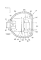
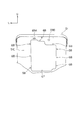
図6は、収納ボックス51の側面図であり、図7は上面図、図8は背面図である。なお、各図において、符号60は、収納ボックス51をメインフレーム4(ステー8B、8B、4F)にボルト締結する際の複数(3個)のボルト挿通孔である。
収納ボックス51は、上方が開口する箱形状を有し、収納ボックス51の前壁51Aの前上部中央には、前方に突出する支持腕部61が一体に突設され、この支持腕部61の軸挿通孔62に挿通された軸を介して乗員用シート52の前端が回動自在に連結される。これによって、乗員用シート52が収納ボックス51の上部開口を開閉自在に回動し、また、乗員用シート52は図示せぬロック機構によって閉状態にロック可能に構成されている。
収納ボックス51の前壁51Aは、車体フレーム2に支持した状態で、図3に示すように、車体フレーム2のメインフレーム4近傍まで延出し、この収納ボックス51の底壁51Bは、図3および図6に示すように、この前壁51Aの下縁からメインフレーム4の傾斜に沿って後ろ下がりに延びる前側底壁51B1と、この前側底壁51B1の後端から上方へ垂直に延びる垂直壁51B2を介して第2リヤフレーム8、8よりも上方近傍の位置から第2リヤフレーム8、8の傾斜に略沿って後ろ上がりに延びる後側底壁51B3とを有している。
6 is a side view of the
The
The
すなわち、収納ボックス51の前側部分(前側底壁51B1に対応する収納部分)は、第2リヤフレーム8、8間を下方に延在してメインフレーム4近傍に位置して収納ボックス51の最深部を構成する膨出部63を形成しており、この部分は、図1に示すように、ハーフタイプのヘルメット100をバイザー101側を下にして収納ボックス51内に挿入した場合に、ヘルメット100の前側(バイザー101側の部分)を収容可能な前後長、深さおよび幅に形成される。
また、この膨出部63の底(前側底壁51B1)には、垂直壁51B2の前方に間隔を空けて上方へ突出するリブ(収納部品位置決め用リブ)64が設けられるとともに、このリブ64の前後に水抜き用の孔65、66が設けられ、このリブ64は、ヘルメット100のバイザー101が当接して該ヘルメット100の収納位置を位置決め可能な位置に予め一体に設けられている。
That is, the front portion of the storage box 51 (the storage portion corresponding to the front bottom wall 51B1) extends downward between the second
Further, a rib (storage component positioning rib) 64 is provided on the bottom (front bottom wall 51B1) of the bulging
この収納ボックス51の後側部分には、バッテリ55を収容するバッテリ収納部71が設けられるとともに、バッテリ収納部71に収納されたバッテリ55を上方から覆うバッテリカバー81が着脱自在に設けられる。まず、バッテリ収納部71について詳述する。
収納ボックス51の後側底壁51B3の中央部分には、図6に示すように、側面視で、垂直壁51B2の上端から後ろ下がりに延びる第1傾斜面72と、第1傾斜面72の後下部から後ろ上がりに延びる第2傾斜面73とによってV字状の底断面形状が形成され、これらによって、同図に示すように、バッテリ55の前部を収納するバッテリ収納用凹部(バッテリ前部収納部)75が形成されている。また、このバッテリ収納用凹部75の最深部には、配線通し用或いは水抜き用として使用される孔75Aが形成されている。
A
As shown in FIG. 6, the central portion of the
また、収納ボックス51の後壁51Cには、車両後方に突出してバッテリ55の後部を収容するバッテリ収納用突出部(バッテリ後部収納部)76が形成されている。このバッテリ収納用突出部76は、バッテリ収納用凹部75の第2傾斜面73に連続する第3傾斜面77を形成するとともに、この第3傾斜面77の後端から第3傾斜面77に対して垂直方向(第1傾斜面72と略並行)の前上がり傾斜面である第4傾斜面78を形成する。
ここで、このバッテリ収納用突出部76は、収納ボックス51とは別部品で構成されている。すなわち、図8に示すように、収納ボックス51の後壁51Cには、開口部67が設けられており、この開口部67を塞ぐようにバッテリ収納用突出部76があてがわれ、開口部67の周囲に形成された複数の孔68を利用してバッテリ収納用突出部76がねじ等で連結されるようになっている。なお、図7も図8と同様にバッテリ収納用突出部76を取り外した状態を示している。
The
Here, the
バッテリ収納部71に収納されるバッテリ55は、一般的なバッテリと同様に直方体形状を有しており、上記バッテリ収納部71は、バッテリ55を水平配置した場合の水平断面の長手方向を車両の前後方向に一致させたレイアウト(縦置きレイアウト)で、バッテリ55を収納するように構成されている。つまり、図6および図7に示すように、バッテリ55の水平断面の長手寸法を値BL、短手寸法を値BHで表記した場合に、バッテリ収納部71の車両前後方向の離間距離は値BLより若干大きく(図6参照)、車両幅方向の離間距離は値BHより若干大きく形成されている(図7参照)。
このように、バッテリ55を車幅方向中央に縦置きレイアウトしたので、収納ボックス51内のバッテリ55の左右に比較的大きな収納スペースを確保できるとともに、比較的重量を有するバッテリ55を車幅方向中央に配置する分、車両の重心位置を車幅方向中央に容易に設定することが可能になる。また、バッテリ55を縦置きにすることで、バッテリ55の側方に支持部(ボルト挿通孔60等)を配置でき、収納ボックス51の幅を大きくすることなく、重量物であるバッテリ55近傍に支持部を配置することができる。
The
Thus, since the
このため、図1に示すように、ヘルメット100の内側空間(頭が入る空間)にバッテリ55の収納ボックス51内に突出する部分を収納させ、ヘルメット100の両サイドの部分をバッテリ55の左右のスペースに収容させることができ、つまり、ヘルメット100を収納ボックス51内に効率よく収納させることができる。
なお、収納ボックス51の開口縁51Xは、車両側面視で、前下がりに傾斜しており、これによって、収納ボックス51内のヘルメット100の一部を開口縁51Xの外に露出させ、該露出部分を乗員用シート52で覆うようにしている(図1参照)。これによれば、乗員用シート52を開ければヘルメット100の一部が露出し、この露出する部分を手で持ってヘルメット100の取り出し、収納を容易に行うことができる。また、バッテリ55を収納ボックス51から着脱する際、収納ボックス51の前側からバッテリ55を着脱すれば、収納ボックス51の上下移動量を少なくすることができ、バッテリ55の着脱作業を容易にすることができる。
For this reason, as shown in FIG. 1, the part which protrudes in the
Note that the
また、図6に示すように、車両側面視で、バッテリ55の傾斜角度θは、収納ボックス51の後壁51C(垂直壁)に対して90度以上の角度(つまり、鈍角)に設定され、これによって、バッテリ55の後下部が収納ボックス51の外側に突出する。このレイアウトの場合、図3に示すように、収納ボックス51の後壁51Cと、燃料タンク50の後方斜め下がりに傾斜した前部50Aと、リヤフレーム6、6とで囲まれた略三角形の空間をバッテリ55のレイアウトスペースとして効率よく利用することができるとともに、バッテリ55を収納ボックス51から取り出すとき、バッテリ55を後壁51Cから離れる方向に外すことになるので、バッテリ55の取り外しが容易になる。
しかも、図6に示すように、バッテリ55の外形をバッテリ55の上面或いは底面に対して直交する方向へ投影した外形投影面55Xが、収納ボックス51の開口縁51X内を通るので、バッテリ55を着脱する際に開口縁51Xが邪魔にならず、バッテリ55の着脱作業をより容易にすることができる。
Further, as shown in FIG. 6, in the vehicle side view, the inclination angle θ of the
In addition, as shown in FIG. 6, an outer
次にバッテリカバー81について説明する。図9はバッテリカバー81の斜視図である。バッテリカバー81は、バッテリ収納部71に収納されて収納ボックス51内に突出するバッテリ55の突出部分を覆うカバーであり、収納ボックス51の後壁51Cに連設される第1カバー部81Aと、この第1カバー部81Aから膨出してバッテリ55の突出部分の外形状に略沿った形状の第2カバー部81Bとを有している。
第1カバー部81Aの上部には、収納ボックス51の後壁51Cに形成された開口部(係合孔)69A(図6参照)に係合される係合爪82と、第1カバー部81Aを収納ボックス51の後壁51Cに形成されたねじ孔69B(図6参照)にねじ止めするためのねじ止め部83とが一体に形成され、また、第2カバー部81Bの上記係合爪82から最も離れた前下部には、収納ボックス51の後側底壁51B3に形成された左右一対の開口部(係合孔)69C、69C(図7参照)に挿入される左右一対の係合爪84、84が一体に形成されている。
Next, the
At the upper part of the
このため、バッテリカバー81を装着する場合は、バッテリカバー81の左右一対の係合爪84、84を収納ボックス51の後側底壁51B3に形成された左右一対の開口部69C、69Cに挿入し、この挿入部分を基準にしてバッテリカバー81を収納ボックス51の後壁51C側に回動させれば、バッテリカバー81の係合爪82が、収納ボックス51の後壁51Cに形成された開口部69Aに係合し、これら係合により、バッテリカバー81を収納ボックス51に容易に仮止めすることができる。そして、バッテリカバー81のねじ止め部83を収納ボックス51のねじ孔69Bにねじ止めすれば、バッテリカバー81が収納ボックス51に確実に固定されるので、バッテリカバー81の脱着作業を容易に行うことができる。
このようにバッテリ55をバッテリカバー81で上方から覆うので、バッテリ55の上面に露出する電極部や配線の露出を回避することができる。
また、バッテリカバー81の第2カバー部81Bの上面および前面の各々に形成された凹部86、87が、バッテリ55の上面および前面に各々当接してバッテリ55をバッテリ収納部71側へ押さえるので、これにより、バッテリ55をバッテリ収納部71へ確実に支持させることができ、バッテリ55の位置ずれを防止できる。
Therefore, when mounting the
Thus, since the
In addition, since the
本実施形態では、図1および図3に示すように、バッテリ55とこのバッテリ55を収納するバッテリ収納部71とを、車両側面視で、リヤフレーム6の上方(リヤフレーム6を基準にしたときのリヤフレーム6の上側)に配置したので、バッテリ55の少なくとも一部を収納ボックス51内に突出させて収納させた場合でも、バッテリ55およびバッテリ収納部71をリヤフレーム6、6間から外すことができ、リヤフレーム6、6間をつなぐクロスフレーム8Aを設ける際、このクロスフレーム8Aのレイアウト自由度を向上することができる。例えば、上記図3に示したクロスフレーム8Aの位置は、その前後方向に変更可能である。また、実施例のようにバッテリ55の下方に配置することもできる。これによって、車体フレーム2の剛性バランスの調整の自由度も上げることができる。
しかも、バッテリ55およびバッテリ収納部71を、収納ボックス51の左右一対のリヤフレーム6、6間に膨出する膨出部63と異なる位置に配置したので、膨出部63を小さくできると共に、リヤフレーム6、6間にバッテリ55、バッテリ収納部71および収納ボックス51がないスペースを確実に確保することができ、リヤフレーム6、6間をつなぐクロスフレーム8Aのレイアウトスペースを確実に確保できる。
また、上記バッテリ55を、車両側面視で、後ろ上がりに延びるリヤフレーム6、6の傾斜に沿うように傾斜して設け、傾斜した状態でその一部を収納ボックス51内に突出させたので、バッテリ55をリヤフレーム6、6に近接して配置することが可能になり、これにより、バッテリ55をリヤフレーム6、6寄りに配置できる分だけ、バッテリ55の収納ボックス51内への突出量を減らすことができ、収納ボックス51内に占めるバッテリ容積を低減することができる。
In this embodiment, as shown in FIGS. 1 and 3, the
Moreover, since the
Further, the
また、バッテリ収納部71は、収納ボックス51の後側に設けられ、バッテリ55の上面を前下がりに傾斜させてバッテリ55を支持するので、バッテリ55を収納ボックス51の後側に設けたバッテリ収納部71から着脱し易くなる。
また、収納ボックス51の後方に燃料タンク50を配置し、収納ボックス51の後壁51Cと燃料タンク50の前部50Aとリヤフレーム6、6とで囲まれた空間内にバッテリ55の後部を位置させたので、収納ボックス51、燃料タンク50およびリヤフレーム6、6との間の空間をバッテリ55のレイアウトスペースに有効利用することができ、これによっても、収納ボックス51に占めるバッテリ容積を低減することができる。
さらに、バッテリ55は、その長手方向を車両の前後方向に沿わせて配置され、このバッテリ55の収納ボックス51内に突出する部分をヘルメット100が上方から覆って該ヘルメット100が収納ボックス51内に収納されるように構成したので、収納ボックス51内のバッテリ55の左右に比較的大きな収納スペースを確保でき、ヘルメット100を収納可能にしつつ収納ボックス51の車幅方向への大型化を回避することができる。
Further, since the
In addition, the
Further, the
また、バッテリ55は、車両側面視で、収納ボックス51内に傾斜して配置され、このバッテリ55の外形を当該バッテリ55の上面或いは底面に対して直交する方向へ投影した外形投影面55Xが収納ボックス51の開口縁51X内を通るようにしたので、バッテリ55を着脱する際に開口縁51Xが邪魔にならず、バッテリ55の着脱作業を容易にすることができる。
さらに、左右一対のリヤフレーム6、6の前部間にクロスフレーム8Aを有し、このクロスフレーム8A近傍位置でリヤフレーム6、6が収納ボックス51を支持するようにしたので、クロスフレーム8Aを車両前寄りに配置でき、その分、リヤフレーム6、6間に車両構成部品のレイアウトスペースを確保し、或いは、リヤフレーム6、6間の空きスペースを広くすることができる。
本構成では、図3に示すように、クロスフレーム8Aをリヤフレーム6、6の前部に設けることでクロスフレーム8A後方に空いたスペースを、リヤフェンダ18Eのレイアウトスペースに利用しており、これによって、リヤフェンダ18Eを車両前側に詰めて配置でき、これに伴い、後輪15を従来よりも前寄りに配置でき、つまり、前輪軸と後輪軸との間の距離(ホイールベース)を短縮したり、車両の前後長を短くしたりすることができる。また、クロスフレーム8A近傍位置でリヤフレーム6、6が収納ボックス51を支持するので、収納ボックス51を強固に支持することができる。
Further, the
Further, a
In this configuration, as shown in FIG. 3, by providing the
以上、一実施形態に基づいて本発明を説明したが、本発明はこれに限定されるものでなく、種々の設計変形を行うことができる。例えば、上記実施形態では、左右一対のリヤフレーム6、6が、第1リヤフレーム(シートレール)7、7と、第1リヤフレーム7、7の前部上方に配置される第2リヤフレーム(サブフレーム)8、8とで構成される場合を説明したが、これに限らず、これらフレーム7、8やレイアウトは適宜変更してもよく、また、リヤフレーム6、6がシートレールだけの左右1本のフレームであってよい。また、メインフレーム4が1本の車体フレーム2に限らず、左右一対のメインフレームを備える車体フレームにも本発明を適用してもよい。また、上記実施形態では、収納ボックス51をメインフレーム4上かつ左右一対のリヤフレーム6、6上に配置する場合を説明したが、これに限らず、フレーム構成によっては収納ボックス51がメインフレーム4上に配置されずにリヤフレーム6、6上に配置される場合にも本発明を適用可能である。
また、上記実施形態では、単気筒エンジンを有する自動二輪車のバッテリ配置構造に本発明を適用する場合を説明したが、これに限らず、他の自動二輪車のバッテリ配置構造にも本発明を広く適用が可能である。
As mentioned above, although this invention was demonstrated based on one Embodiment, this invention is not limited to this, A various design deformation | transformation can be performed. For example, in the above-described embodiment, the pair of left and right rear frames 6, 6 includes a first rear frame (seat rail) 7, 7 and a second rear frame (above the front part of the first
In the above embodiment, the case where the present invention is applied to the battery arrangement structure of a motorcycle having a single cylinder engine has been described. However, the present invention is not limited to this, and the present invention is widely applied to other battery arrangement structures of motorcycles. Is possible.
1 自動二輪車
2 車体フレーム
3 ヘッドパイプ
4 メインフレーム
5 ピボットブラケット
5A、7C、7C1、7C2、8A クロスフレーム
6 リヤフレーム
7 第1リヤフレーム(シートレール)
8 第2リヤフレーム(サブフレーム)
18 車体カバー
18E リヤフェンダ
20 エンジン)
50 燃料タンク
51 収納ボックス
51X 開口縁
52 乗員用シート
55 バッテリ
63 膨出部
71 バッテリ収納部
75 バッテリ収納用凹部(バッテリ前部収納部)
76 バッテリ収納用突出部(バッテリ後部収納部)
81 バッテリカバー
100 ヘルメット
DESCRIPTION OF
8 Second rear frame (subframe)
18
DESCRIPTION OF
76 Battery storage protrusion (battery rear storage)
81
Claims (7)
前記バッテリとこのバッテリを収納するバッテリ収納部とを、車両側面視で、前記リヤフレームの上方に配置したことを特徴とする自動二輪車のバッテリ配置構造。 A main frame extending rearward and downward from the head pipe, a pair of left and right rear frames connected to the rear portion of the main frame and extending rearward, and disposed on the main frame or the pair of left and right rear frames. In a battery arrangement structure for a motorcycle, comprising: a storage box in which a portion bulges; and a battery storage portion that is provided in the storage box and protrudes into the storage box to support the battery.
A battery arrangement structure for a motorcycle, wherein the battery and a battery storage portion for storing the battery are arranged above the rear frame in a side view of the vehicle.
前記バッテリは、車両側面視で、後ろ上がりに延びる前記リヤフレームの傾斜に沿うように傾斜して設けられ、傾斜した状態でその一部が前記収納ボックス内に突出することを特徴とする自動二輪車のバッテリ配置構造。 The battery arrangement structure of the motorcycle according to claim 1,
The motorcycle according to claim 1, wherein the battery is provided so as to be inclined along the inclination of the rear frame extending rearward in a side view of the vehicle, and a part of the battery projects into the storage box in the inclined state. Battery arrangement structure.
前記バッテリ収納部は、前記収納ボックスの後側に設けられ、前記バッテリの上面を前下がりに傾斜させて前記バッテリを支持することを特徴とする自動二輪車のバッテリ配置構造。 In the battery arrangement structure of the motorcycle according to claim 2,
The battery storage structure for a motorcycle, wherein the battery storage portion is provided on a rear side of the storage box, and supports the battery by tilting an upper surface of the battery forward and downward.
前記収納ボックスの後方に燃料タンクを配置し、
前記収納ボックスの後壁と前記燃料タンクの前部と前記リヤフレームとで囲まれた空間内に、前記バッテリの後部を位置させたことを特徴とする自動二輪車のバッテリ配置構造。 In the battery arrangement structure of the motorcycle according to claim 3,
A fuel tank is arranged behind the storage box,
A battery arrangement structure for a motorcycle, wherein a rear portion of the battery is positioned in a space surrounded by a rear wall of the storage box, a front portion of the fuel tank, and the rear frame.
前記バッテリは、その長手方向を車両の前後方向に沿わせて配置され、このバッテリの前記収納ボックス内に突出する部分をヘルメットが上方から覆って該ヘルメットが前記収納ボックス内に収納されるように構成したことを特徴とする自動二輪車のバッテリ配置構造。 In the battery arrangement structure of the motorcycle according to any one of claims 1 to 4,
The battery is disposed such that its longitudinal direction is along the longitudinal direction of the vehicle, and a helmet covers the portion of the battery protruding into the storage box from above so that the helmet is stored in the storage box. A battery arrangement structure for a motorcycle, characterized in that it is configured.
前記バッテリは、車両側面視で、前記収納ボックス内に傾斜して配置され、このバッテリの外形を当該バッテリの上面或いは底面に対して直交する方向へ投影した外形投影面が前記収納ボックスの開口縁内を通ることを特徴とする自動二輪車のバッテリ配置構造。 In the battery arrangement structure of the motorcycle according to any one of claims 1 to 5,
The battery is inclined and arranged in the storage box in a side view of the vehicle, and an outer projection surface obtained by projecting the outer shape of the battery in a direction perpendicular to the upper surface or the bottom surface of the battery is an opening edge of the storage box. A battery arrangement structure for a motorcycle characterized by passing inside.
前記左右一対のリヤフレームの前部間にクロスフレームを設けたことを特徴とする自動二輪車のバッテリ配置構造。 The battery arrangement structure for a motorcycle according to any one of claims 1 to 6,
A battery arrangement structure for a motorcycle, wherein a cross frame is provided between front portions of the pair of left and right rear frames.
Priority Applications (4)
| Application Number | Priority Date | Filing Date | Title |
|---|---|---|---|
| JP2008245634A JP5112237B2 (en) | 2008-09-25 | 2008-09-25 | Motorcycle battery arrangement structure |
| BRPI0903383-1A BRPI0903383B1 (en) | 2008-09-25 | 2009-09-22 | MOTORCYCLE BATTERY FRAMEWORK |
| ARP090103660 AR074651A1 (en) | 2008-09-25 | 2009-09-23 | TABLE FOR BATTERY DISPOSAL OF A MOTORCYCLE |
| CN 200910178001 CN101683815B (en) | 2008-09-25 | 2009-09-23 | Battery configuration construct of two-wheeled motorcycle |
Applications Claiming Priority (1)
| Application Number | Priority Date | Filing Date | Title |
|---|---|---|---|
| JP2008245634A JP5112237B2 (en) | 2008-09-25 | 2008-09-25 | Motorcycle battery arrangement structure |
Publications (2)
| Publication Number | Publication Date |
|---|---|
| JP2010076538A true JP2010076538A (en) | 2010-04-08 |
| JP5112237B2 JP5112237B2 (en) | 2013-01-09 |
Family
ID=42047279
Family Applications (1)
| Application Number | Title | Priority Date | Filing Date |
|---|---|---|---|
| JP2008245634A Expired - Fee Related JP5112237B2 (en) | 2008-09-25 | 2008-09-25 | Motorcycle battery arrangement structure |
Country Status (4)
| Country | Link |
|---|---|
| JP (1) | JP5112237B2 (en) |
| CN (1) | CN101683815B (en) |
| AR (1) | AR074651A1 (en) |
| BR (1) | BRPI0903383B1 (en) |
Cited By (8)
| Publication number | Priority date | Publication date | Assignee | Title |
|---|---|---|---|---|
| JP2012101565A (en) * | 2010-11-05 | 2012-05-31 | Honda Motor Co Ltd | Saddle riding type electric vehicle |
| JP2013103523A (en) * | 2011-11-10 | 2013-05-30 | Honda Motor Co Ltd | Motorcycle |
| WO2013180199A1 (en) * | 2012-06-01 | 2013-12-05 | スズキ株式会社 | Storage structure for saddled vehicle |
| JP2013249016A (en) * | 2012-06-01 | 2013-12-12 | Suzuki Motor Corp | Helmet storing structure of saddle type vehicle |
| WO2014158103A1 (en) * | 2013-03-29 | 2014-10-02 | Honda Motor Co., Ltd. | Canister mounting structure for a motorcycle |
| US9090217B2 (en) * | 2012-08-28 | 2015-07-28 | Honda Motor Co., Ltd. | Storage part structure for saddle type vehicle |
| JP2016037116A (en) * | 2014-08-06 | 2016-03-22 | スズキ株式会社 | Storage box |
| WO2018047677A1 (en) * | 2016-09-09 | 2018-03-15 | 本田技研工業株式会社 | Battery case for saddled vehicles |
Families Citing this family (3)
| Publication number | Priority date | Publication date | Assignee | Title |
|---|---|---|---|---|
| JP2013095232A (en) * | 2011-10-31 | 2013-05-20 | Honda Motor Co Ltd | Motorcycle |
| WO2014158102A1 (en) * | 2013-03-29 | 2014-10-02 | Honda Motor Co., Ltd. | Canister mounting structure for a motorcycle |
| JP2021062724A (en) * | 2019-10-11 | 2021-04-22 | ヤマハ発動機株式会社 | Saddle-riding type vehicle |
Citations (4)
| Publication number | Priority date | Publication date | Assignee | Title |
|---|---|---|---|---|
| JP2000006870A (en) * | 1998-06-23 | 2000-01-11 | Honda Motor Co Ltd | Rear frame of motor-bicycle, etc. |
| JP2002225765A (en) * | 2001-01-30 | 2002-08-14 | Honda Motor Co Ltd | Accommodation box structure of motorcycle |
| JP2003226281A (en) * | 2002-02-07 | 2003-08-12 | Honda Motor Co Ltd | Battery disposition structure of motorcycle |
| JP2006096133A (en) * | 2004-09-29 | 2006-04-13 | Honda Motor Co Ltd | Motorcycle with stand locking device |
Family Cites Families (5)
| Publication number | Priority date | Publication date | Assignee | Title |
|---|---|---|---|---|
| JP3365688B2 (en) * | 1994-07-25 | 2003-01-14 | 本田技研工業株式会社 | Scooter body structure |
| JP2001171580A (en) * | 1999-12-17 | 2001-06-26 | Honda Motor Co Ltd | Battery arrangement structure of motorcycle |
| CN101439551A (en) * | 2004-07-28 | 2009-05-27 | 邱则有 | Mold for molding hollow thin wall component for filling concrete |
| JP4851717B2 (en) * | 2005-01-11 | 2012-01-11 | 本田技研工業株式会社 | ABS unit arrangement structure for motorcycles |
| JP2008100574A (en) * | 2006-10-18 | 2008-05-01 | Yamaha Motor Co Ltd | Motorcycle |
-
2008
- 2008-09-25 JP JP2008245634A patent/JP5112237B2/en not_active Expired - Fee Related
-
2009
- 2009-09-22 BR BRPI0903383-1A patent/BRPI0903383B1/en active IP Right Grant
- 2009-09-23 AR ARP090103660 patent/AR074651A1/en active IP Right Grant
- 2009-09-23 CN CN 200910178001 patent/CN101683815B/en not_active Expired - Fee Related
Patent Citations (4)
| Publication number | Priority date | Publication date | Assignee | Title |
|---|---|---|---|---|
| JP2000006870A (en) * | 1998-06-23 | 2000-01-11 | Honda Motor Co Ltd | Rear frame of motor-bicycle, etc. |
| JP2002225765A (en) * | 2001-01-30 | 2002-08-14 | Honda Motor Co Ltd | Accommodation box structure of motorcycle |
| JP2003226281A (en) * | 2002-02-07 | 2003-08-12 | Honda Motor Co Ltd | Battery disposition structure of motorcycle |
| JP2006096133A (en) * | 2004-09-29 | 2006-04-13 | Honda Motor Co Ltd | Motorcycle with stand locking device |
Cited By (10)
| Publication number | Priority date | Publication date | Assignee | Title |
|---|---|---|---|---|
| JP2012101565A (en) * | 2010-11-05 | 2012-05-31 | Honda Motor Co Ltd | Saddle riding type electric vehicle |
| JP2013103523A (en) * | 2011-11-10 | 2013-05-30 | Honda Motor Co Ltd | Motorcycle |
| WO2013180199A1 (en) * | 2012-06-01 | 2013-12-05 | スズキ株式会社 | Storage structure for saddled vehicle |
| JP2013249016A (en) * | 2012-06-01 | 2013-12-12 | Suzuki Motor Corp | Helmet storing structure of saddle type vehicle |
| US9090217B2 (en) * | 2012-08-28 | 2015-07-28 | Honda Motor Co., Ltd. | Storage part structure for saddle type vehicle |
| WO2014158103A1 (en) * | 2013-03-29 | 2014-10-02 | Honda Motor Co., Ltd. | Canister mounting structure for a motorcycle |
| CN105073569A (en) * | 2013-03-29 | 2015-11-18 | 本田技研工业株式会社 | Canister mounting structure for a motorcycle |
| JP2016037116A (en) * | 2014-08-06 | 2016-03-22 | スズキ株式会社 | Storage box |
| WO2018047677A1 (en) * | 2016-09-09 | 2018-03-15 | 本田技研工業株式会社 | Battery case for saddled vehicles |
| JPWO2018047677A1 (en) * | 2016-09-09 | 2019-06-27 | 本田技研工業株式会社 | Battery case for straddle-type vehicles |
Also Published As
| Publication number | Publication date |
|---|---|
| AR074651A1 (en) | 2011-02-02 |
| BRPI0903383A2 (en) | 2010-06-01 |
| CN101683815B (en) | 2013-09-04 |
| BRPI0903383B1 (en) | 2019-02-19 |
| JP5112237B2 (en) | 2013-01-09 |
| CN101683815A (en) | 2010-03-31 |
Similar Documents
| Publication | Publication Date | Title |
|---|---|---|
| JP5112237B2 (en) | Motorcycle battery arrangement structure | |
| US8794687B2 (en) | Saddle type vehicle having an accommodation box | |
| JP5399168B2 (en) | Motorcycle | |
| US8851557B2 (en) | Saddle-ride type vehicle | |
| EP2703272B1 (en) | Storage part structure for saddle type vehicle | |
| JP2009012645A (en) | Step holder mounting structure of motorcycle | |
| EP2511164A1 (en) | Saddle type vehicle | |
| JP5021191B2 (en) | Electrical component removal prevention structure | |
| JP4676281B2 (en) | Vehicle flap | |
| JP2014076731A (en) | Saddle riding type vehicle | |
| EP1790557A1 (en) | Motorcycle with a battery case in the rear fender | |
| JP2008081052A (en) | Battery support structure for vehicle | |
| JP4132852B2 (en) | Battery arrangement structure for motorcycles | |
| JPH0648342A (en) | Accommodation box for motorcycle | |
| JP2007176370A (en) | Cover structure of motorcycle | |
| JP2009227219A (en) | Vehicle | |
| JP5212695B2 (en) | Motorcycle | |
| JP2002331977A (en) | Scooter type vehicle | |
| JP2004168084A (en) | Article storage box structure of two-wheeled automobile | |
| JP4641467B2 (en) | Rear structure of motorcycle | |
| JP6348381B2 (en) | Saddle riding vehicle | |
| JP2006151132A (en) | Vehicle | |
| JP2017114343A (en) | Battery storage section structure | |
| JP6625424B2 (en) | Motorcycle canister mounting structure | |
| JP2007076566A (en) | Vehicle body frame of motorcycle |
Legal Events
| Date | Code | Title | Description |
|---|---|---|---|
| A621 | Written request for application examination |
Free format text: JAPANESE INTERMEDIATE CODE: A621 Effective date: 20101126 |
|
| A131 | Notification of reasons for refusal |
Free format text: JAPANESE INTERMEDIATE CODE: A131 Effective date: 20120417 |
|
| A977 | Report on retrieval |
Free format text: JAPANESE INTERMEDIATE CODE: A971007 Effective date: 20120419 |
|
| A521 | Written amendment |
Free format text: JAPANESE INTERMEDIATE CODE: A523 Effective date: 20120521 |
|
| RD02 | Notification of acceptance of power of attorney |
Free format text: JAPANESE INTERMEDIATE CODE: A7422 Effective date: 20120521 |
|
| TRDD | Decision of grant or rejection written | ||
| A01 | Written decision to grant a patent or to grant a registration (utility model) |
Free format text: JAPANESE INTERMEDIATE CODE: A01 Effective date: 20121002 |
|
| A01 | Written decision to grant a patent or to grant a registration (utility model) |
Free format text: JAPANESE INTERMEDIATE CODE: A01 |
|
| A61 | First payment of annual fees (during grant procedure) |
Free format text: JAPANESE INTERMEDIATE CODE: A61 Effective date: 20121010 |
|
| FPAY | Renewal fee payment (event date is renewal date of database) |
Free format text: PAYMENT UNTIL: 20151019 Year of fee payment: 3 |
|
| R150 | Certificate of patent or registration of utility model |
Ref document number: 5112237 Country of ref document: JP Free format text: JAPANESE INTERMEDIATE CODE: R150 Free format text: JAPANESE INTERMEDIATE CODE: R150 |
|
| LAPS | Cancellation because of no payment of annual fees |