JP2010075987A - Press machine - Google Patents
Press machine Download PDFInfo
- Publication number
- JP2010075987A JP2010075987A JP2008249947A JP2008249947A JP2010075987A JP 2010075987 A JP2010075987 A JP 2010075987A JP 2008249947 A JP2008249947 A JP 2008249947A JP 2008249947 A JP2008249947 A JP 2008249947A JP 2010075987 A JP2010075987 A JP 2010075987A
- Authority
- JP
- Japan
- Prior art keywords
- speed
- cushion
- time point
- slide
- press
- Prior art date
- Legal status (The legal status is an assumption and is not a legal conclusion. Google has not performed a legal analysis and makes no representation as to the accuracy of the status listed.)
- Granted
Links
Images


Abstract
Description
本発明は、プレス機械に関する。 The present invention relates to a press machine.
プレス機械では、駆動モータによる回転運動をスライドの昇降運動に変換する。スライドの下面には上金型が取り付けられており。上金型の下方には下金型が配置される。これら上金型と下金型との間でパネルなどの被加工物を挟んでプレス成形する。 In the press machine, the rotational movement by the drive motor is converted into the up-and-down movement of the slide. An upper mold is attached to the lower surface of the slide. A lower mold is disposed below the upper mold. A press work is performed by sandwiching a workpiece such as a panel between the upper mold and the lower mold.
駆動モータとしてサーボモータを用いたプレス機械では、1プレスサイクル中にスライドを自由に加速、減速させるようにスライドの動作設定が可能である。これは、サーボモータの回転速度を自在に設定できるからである。なお、1プレスサイクルは、スライドが、下降して被加工物をプレス成形し、その後、上昇して所定の待機位置へ戻るまでの期間をいう。 In a press machine using a servo motor as a drive motor, the slide operation can be set so as to freely accelerate and decelerate the slide during one press cycle. This is because the rotation speed of the servo motor can be set freely. One press cycle refers to a period from when the slide descends to press-mold the workpiece, and then rises to return to a predetermined standby position.
上述のスライド動作の設定は、1プレスサイクル中の各時点を指定し、各時点毎に動作速度を設定することで行うことができる。
1プレスサイクル中の各時点の指定は、スライドの昇降運動の昇降位置または前記回転運動の回転角によりなされる。前記回転運動の回転角で各時点を指定する場合には、駆動モータの回転シャフトの回転角で前記各時点を指定するか、もしくは、駆動モータとスライドとの間に連結されているクランク軸の回転角で前記各時点を指定する。
前記動作速度の指定は、前記昇降運動の昇降速度または前記回転運動の回転速度によりなされる。前記昇降速度で動作速度を設定する場合には、指定した前記各時点毎にスライドの昇降速度を設定する。前記回転運動の回転角で動作速度を設定する場合には、指定した前記各時点毎に、駆動モータの回転シャフトの回転速度を設定するか、もしくは、クランク軸の回転速度を設定する。
The above-described slide operation can be set by designating each time point in one press cycle and setting an operation speed for each time point.
The designation of each point in time in one press cycle is made by the raising / lowering position of the raising / lowering movement of the slide or the rotation angle of the rotational movement. When each time point is specified by the rotation angle of the rotary motion, each time point is specified by the rotation angle of the rotation shaft of the drive motor, or the crankshaft connected between the drive motor and the slide Each time point is specified by a rotation angle.
The operation speed is designated by the ascending / descending speed of the elevating movement or the rotating speed of the rotating movement. When the operation speed is set at the up / down speed, the slide up / down speed is set at each designated time point. When setting the operation speed with the rotation angle of the rotary motion, the rotation speed of the rotation shaft of the drive motor or the rotation speed of the crankshaft is set for each designated time point.
本願の先行技術文献として,例えば下記の特許文献1、2がある。
上述のスライド動作の設定では、1プレス成形期間の各時点の指定は、前記昇降位置または回転角のどちらか一方の単位でなされ、前記各時点に対する動作速度の設定は、前記昇降速度または回転速度のどちらか一方の単位でなされていた。 In the above-described slide operation setting, each time point in one press molding period is specified in either the ascending / descending position or the rotation angle, and the operation speed setting for each time point is the ascending / descending speed or rotating speed. It was made in either unit.
このような手法では、次のように、プレス機械の動作設定や動作調整を行うユーザにとって、負担が大きくなる場合がある。
即ち、1プレスサイクル中のある時点では動作速度として前記昇降速度を設定し、別の時点では動作速度として前記回転速度を設定したい場合には、いずれか一方の時点では昇降速度から回転速度への単位変換または逆の単位変換が必要になる。このような単位変換は、プレス機械のユーザにとって大きな負担となっていた。
なお、1プレスサイクル中のある時点を、前記昇降位置で指定し、別の時点を前記回転角で指定したい場合にも、いずれか一方の時点の指定では、前記昇降位置から回転角への単位変換または逆の単位変換が必要になる。このような単位変換も、プレス機械のユーザにとって大きな負担となっていた。
In such a method, as described below, the burden on the user who performs operation setting and operation adjustment of the press machine may increase.
That is, when it is desired to set the ascending / descending speed as an operating speed at a certain point in one press cycle and to set the rotational speed as an operating speed at another point, the elevating speed is changed from the ascending / descending speed to the rotating speed at any one point. Unit conversion or reverse unit conversion is required. Such unit conversion has been a heavy burden for users of press machines.
Even when one point in one press cycle is specified by the lift position and another time point is specified by the rotation angle, the unit from the lift position to the rotation angle is specified in either time point. Conversion or reverse unit conversion is required. Such unit conversion is also a heavy burden for the press machine user.
そこで、本発明の目的は、プレス機械の動作設定や動作調整において、ユーザにかかる負担を大幅に低減できるプレス機械を提供することにある。 Therefore, an object of the present invention is to provide a press machine that can greatly reduce the burden on the user in the operation setting and operation adjustment of the press machine.
上記目的を達成するため、本発明によると、被加工物を挟んでプレス成形する上金型および下金型と、
前記上金型を駆動するための駆動モータと、
前記駆動モータによる回転運動を、前記上金型が固定されたスライドの昇降運動に変換する変換機構と、を備えるプレス機械であって、
被加工物を1回プレス成形するための1プレスサイクルにおける前記スライドの動作パターンを記憶する動作パターン記憶装置と、
前記動作パターンに基づいて前記駆動モータを制御するスライド制御装置と、
前記1プレスサイクル内の各時点毎に、前記動作パターンを定めるための動作速度を設定できるように、人が操作可能な入力装置と、を備え、
前記入力装置は、前記各時点毎に、前記回転運動の回転速度と前記昇降運動の昇降速度のいずれかを任意に選択し、該選択した前記回転速度または前記昇降速度を該時点の動作速度として所望の値に設定できるように人が操作可能であり、
前記入力装置により前記各時点毎に設定された前記動作速度に基づいて前記動作パターンを計算する計算装置を、さらに備える、ことを特徴とするプレス機械が提供される。
In order to achieve the above object, according to the present invention, an upper mold and a lower mold that are press-molded with a workpiece interposed therebetween,
A drive motor for driving the upper mold;
A conversion mechanism that converts the rotational movement by the drive motor into the up-and-down movement of the slide to which the upper mold is fixed, and a press machine comprising:
An operation pattern storage device for storing an operation pattern of the slide in one press cycle for press-molding a workpiece once;
A slide control device for controlling the drive motor based on the operation pattern;
An input device that can be operated by a person so that an operation speed for determining the operation pattern can be set for each time point in the one press cycle,
The input device arbitrarily selects either the rotational speed of the rotary motion or the vertical speed of the lifting motion at each time point, and uses the selected rotational speed or the lifting speed as the operation speed at the time point. It can be operated by a person so that it can be set to the desired value.
A press machine is provided, further comprising a calculation device that calculates the operation pattern based on the operation speed set for each time point by the input device.
上述の本発明のプレス機械では、前記入力装置は、人の操作により、前記回転運動の回転速度と前記昇降運動の昇降速度のいずれかを任意に選択し、該選択した前記回転速度または前記昇降速度を該時点の動作速度として設定できように構成され、計算装置は、前記入力装置により前記各時点毎に設定された前記動作速度に基づいて前記動作パターンを計算するので、ある時点では前記回転速度を動作速度として設定し、別の時点では前記昇降速度を動作速度として設定したい場合に回転速度と昇降速度との間で単位変換する計算を、ユーザが行う必要がなくなる。従って、プレス機械調整においてユーザにかかる負担が大幅に低減される。
特に、本発明は次の場合に非常に有効である。上金型および下金型が被加工物に接触してプレス成形を行っているプレス成形期間については、スライドの昇降速度を調整することで被加工物の成形性を調整できるので、プレス成形期間では前記昇降速度を直接設定したい場合がある。一方、スライドが下死点に到達した後は、スライドをできるだけ早く上昇させたいため、前記回転運動の最大回転速度を直接設定したい場合がある。これについて、本発明では、プレス成形期間では前記昇降速度を直接設定することで成形性を調整し、これと同時に、スライドが下死点に到達した以降では回転運動の最大回転速度を直接設定することが可能になり、非常に有効である。
さらに、本発明では、プレス成形中においてスライドの下降速度を変化させる設定も可能である。例えば、プレス成形中の任意の前記昇降位置(例えば下死点)でスライドを停止させる設定も可能であり、この昇降位置から駆動モータを逆回転させてスライドを上昇させる設定も可能である。これにより、被加工物が上金型または下金型に流れ込む量を細かく制御することが可能となり、「割れ」や「しわ」の発生を抑制することが可能となる。よって、本発明により、従来技術より自由度の高い動作設定が実現され、ユーザの設定に対する制約が大幅に緩和される。
また、駆動モータが逆回転する戻り区間においても、この逆回転により一旦上昇したスライドを停止させ、さらに、駆動モータの回転を反転させて正回転に戻すことで、(再度)下死点を通過させるような設定も可能であり、従来技術よりも、動作設定の制約を大幅に緩和させることができる。
In the above-described press machine of the present invention, the input device arbitrarily selects one of the rotational speed of the rotary motion and the vertical speed of the lift motion by a human operation, and the selected rotational speed or the lift The calculation device is configured to be able to set the speed as the operation speed at the time, and the calculation device calculates the operation pattern based on the operation speed set for each time by the input device. When the speed is set as the operation speed and the elevation speed is set as the operation speed at another time, it is not necessary for the user to perform a unit conversion between the rotation speed and the elevation speed. Therefore, the burden on the user in press machine adjustment is greatly reduced.
In particular, the present invention is very effective in the following cases. The press molding period in which the upper mold and the lower mold are in contact with the workpiece to perform press molding can adjust the formability of the workpiece by adjusting the lifting and lowering speed of the slide. Then, there are cases where it is desired to directly set the lifting speed. On the other hand, after the slide reaches the bottom dead center, there is a case where it is desired to directly set the maximum rotational speed of the rotational motion in order to raise the slide as soon as possible. In this regard, in the present invention, the formability is adjusted by directly setting the lifting speed during the press molding period, and at the same time, the maximum rotational speed of the rotational motion is directly set after the slide reaches the bottom dead center. It is possible and very effective.
Furthermore, in the present invention, it is possible to set to change the descending speed of the slide during press molding. For example, it is possible to set the slide to stop at an arbitrary lifting position (for example, bottom dead center) during press molding, and it is also possible to set the slide to be lifted by reversely rotating the drive motor from this lifting position. This makes it possible to finely control the amount of work piece flowing into the upper mold or the lower mold, and to suppress the occurrence of “cracking” and “wrinkles”. Therefore, according to the present invention, an operation setting having a higher degree of freedom than that of the prior art is realized, and restrictions on user settings are greatly relaxed.
Also, in the return section where the drive motor rotates in reverse, the slide once raised by this reverse rotation is stopped, and the rotation of the drive motor is reversed and returned to the normal rotation, so that it passes the bottom dead center (again). Such a setting is also possible, and the restriction on the operation setting can be greatly relaxed as compared with the prior art.
本発明の好ましい実施形態によると、前記入力装置は、前記各時点を指定できるように人が操作可能であり、
前記入力装置は、前記各時点毎に、前記昇降運動の昇降位置と前記回転運動の回転角のいずれでも当該時点を指定できるように人が操作可能である。
According to a preferred embodiment of the present invention, the input device is operable by a person so that the respective time points can be designated,
The input device can be operated by a person at each time point so that the time point can be designated by either the lift position of the lift movement or the rotation angle of the rotary movement.
前記入力装置は、前記各時点毎に、前記昇降運動の昇降位置と前記回転運動の回転角のいずれでも当該時点を指定できるように人が操作可能であるので、ある時点は前記昇降位置で指定し、別の時点は前記回転角で指定したい場合に、前記昇降位置と前記回転角との間で単位変換する計算をユーザが行う必要がなくなる。従って、プレス機械調整においてユーザにかかる負担が大幅に低減される。 Since the input device can be operated by a person so that the time point can be specified at either the lifting position of the lifting movement or the rotation angle of the rotary movement at each time point, a certain time point is specified by the lifting position. However, when it is desired to designate another time by the rotation angle, it is not necessary for the user to perform a unit conversion between the lift position and the rotation angle. Therefore, the burden on the user in press machine adjustment is greatly reduced.
また、本発明の好ましい実施形態によると、前記計算装置により計算された前記動作パターンを表示する表示装置を備え、
前記動作パターンは、次の(A)と(B)の関係、または、次の(C)と(D)の関係である。
(A)経過時間または経過時間に比例して値が進行する変数
(B)前記経過時間または前記変数の各値における前記昇降運動の昇降位置、前記昇降運動の昇降速度、前記回転運動の回転角、もしくは、前記回転運動の回転速度
(C)前記昇降運動の昇降位置または前記回転運動の回転角
(D)前記昇降運動の昇降位置または前記回転運動の回転角の各値における前記昇降運動の昇降速度、もしくは、前記回転運動の回転速度
Further, according to a preferred embodiment of the present invention, the display device displays the operation pattern calculated by the calculation device,
The operation pattern is the following relationship (A) and (B) or the following relationship (C) and (D).
(A) Elapsed time or a variable whose value advances in proportion to the elapsed time (B) Elevating position of the elevating movement, elevating speed of the elevating movement, or rotation angle of the rotating movement at the elapsed time or each value of the variable Or the rotational speed of the rotary motion (C) the lift position of the lift motion or the rotation angle of the rotary motion (D) the lift of the lift motion at each value of the lift position of the lift motion or the rotation angle of the rotary motion Speed or rotational speed of the rotary motion
このように、上述の動作パターンを表示装置により表示できるので、動作パターンを表示装置上で確認できる。従って、動作パターンの設定ミスを防止でき、動作パターンの設定調整に便利である。
好ましくは、前記表示装置は、前記動作パターンをグラフで表示する。これにより、動作パターンを視覚的に確認できる。
Thus, since the above-described operation pattern can be displayed on the display device, the operation pattern can be confirmed on the display device. Therefore, an operation pattern setting error can be prevented, which is convenient for operation pattern setting adjustment.
Preferably, the display device displays the operation pattern as a graph. Thereby, the operation pattern can be visually confirmed.
本発明の好ましい実施形態によると、前記表示装置は、次の(a),(b)を同時に表示する。
(a)前記(A)と、前記(B)の前記昇降位置もしくは前記回転角との関係
(b)前記(A)と、前記(B)の前記昇降速度もしくは前記回転速度との関係
According to a preferred embodiment of the present invention, the display device displays the following (a) and (b) simultaneously.
(A) Relationship between (A) and the lift position or rotation angle of (B) (b) Relationship between (A) and the lift speed or rotation speed of (B)
このように、前記(a),(b)を同時に表示することで、1プレスサイクルの全体にわたって、前記昇降位置もしくは前記回転角の時間変化を確認できるだけでなく、これと同時に、前記昇降速度もしくは前記回転速度の時間変化も確認できる。 Thus, by simultaneously displaying (a) and (b), not only can the time change of the lift position or the rotation angle be confirmed throughout the press cycle, but at the same time, the lift speed or The time change of the rotational speed can also be confirmed.
また、本発明の好ましい実施形態によると、ダイクッション装置を備え、
このダイクッション装置は
上金型と下金型との間で被加工物がプレス成形されるプレス成形時に、被加工物を上金型との間に挟みながら下降する可動部と、
この可動部にクッション力を付与する駆動装置と、
前記1プレスサイクルにおける前記クッション力のクッションパターンを記憶するクッションパターン記憶装置と、
前記クッションパターンに基づいて前記駆動装置を制御するクッション制御装置と、を備え、
前記入力装置は、前記1プレスサイクル内の各時点毎に、前記クッションパターンを定めるためのクッション力を設定できるように、人が操作可能であり、
前記クッションパターンを定める当該各時点は、前記動作速度の設定に関する前記各時点のいずれか、または、他の任意の時点である。
According to a preferred embodiment of the present invention, the die cushion device is provided,
This die cushion device has a movable part that descends while sandwiching the workpiece between the upper die and the upper die when the workpiece is press-molded between the upper die and the lower die,
A driving device for applying a cushioning force to the movable part;
A cushion pattern storage device for storing a cushion pattern of the cushion force in the one press cycle;
A cushion control device that controls the drive device based on the cushion pattern,
The input device is operable by a person so that a cushion force for determining the cushion pattern can be set for each time point in the one press cycle,
The respective time points for defining the cushion pattern are any of the above time points related to the setting of the operation speed, or any other time points.
このように、前記入力装置は、前記1プレスサイクル内の各時点毎に、前記クッションパターンを定めるためのクッション力を設定できるように、人が操作可能であるので、スライドの動作パターンに合わせたクッションパターンを簡単に設定できる。従って、スライドの動作パターンに合わせたクッションパターン設定の複雑さを解消でき、ユーザによるクッション力の設定・調整負担が大幅に低減される。
例えば、表示装置に表示された動作パターンを確認しながら、各時点毎にクッション力を設定でき、ユーザによるクッション力調整負担が大幅に低減される。
また、前記クッションパターンを定める各時点は、前記動作速度が設定された前記各時点以外の任意の時点であってもよいので、前記動作速度が設定された時点以外の時点で、クッション力を設定または変更したい場合でも、このような設定、変更を容易に行うことができ、ユーザによるクッション力の設定・調整負担が大幅に低減される。
Thus, since the input device can be operated by a person so that the cushion force for determining the cushion pattern can be set at each time point in the one press cycle, it is adapted to the slide movement pattern. Cushion pattern can be set easily. Therefore, the complexity of setting the cushion pattern in accordance with the slide operation pattern can be eliminated, and the burden of setting and adjusting the cushion force by the user is greatly reduced.
For example, while confirming the operation pattern displayed on the display device, the cushion force can be set at each time point, and the burden of adjusting the cushion force by the user is greatly reduced.
In addition, each time point defining the cushion pattern may be any time point other than the respective time points when the operation speed is set, so the cushion force is set at a time point other than the time point when the operation speed is set. Alternatively, even when it is desired to change, such setting and changing can be easily performed, and the burden of setting and adjusting the cushion force by the user is greatly reduced.
本発明の好ましい実施形態によると、前記プレス機械に取り付けられている上金型および下金型を別の上金型および下金型に変更可能であり、
前記上金型および下金型毎に、該前記上金型および下金型を示す識別情報と関連付けて前記動作パターンを記憶するデータ管理装置を備え、
前記識別情報をデータ管理装置に入力ことで、該識別情報と関連付けられた前記動作パターンが前記制御装置に使用されるようになっている。
According to a preferred embodiment of the present invention, the upper die and the lower die attached to the press machine can be changed to different upper die and lower die,
A data management device that stores the operation pattern in association with identification information indicating the upper mold and the lower mold for each of the upper mold and the lower mold,
By inputting the identification information to the data management device, the operation pattern associated with the identification information is used by the control device.
このように、前記識別情報をデータ管理装置に入力することで、該識別情報と関連付けられた前記動作パターンが前記制御装置に自動的に使用されるようになっているので、金型変更時のプレス機械動作設定において、ユーザにかかる負担が大幅に低減される。 Thus, by inputting the identification information to the data management device, the operation pattern associated with the identification information is automatically used by the control device. In the press machine operation setting, the burden on the user is greatly reduced.
上述した本発明によると、プレス機械の動作設定や動作調整において、ユーザにかかる負担を大幅に低減できる。 According to the above-described present invention, it is possible to greatly reduce the burden on the user in the operation setting and operation adjustment of the press machine.
本発明を実施するための最良の実施形態を図面に基づいて説明する。なお、各図において共通する部分には同一の符号を付し、重複した説明を省略する。 The best mode for carrying out the present invention will be described with reference to the drawings. In addition, the same code | symbol is attached | subjected to the common part in each figure, and the overlapping description is abbreviate | omitted.
図1は、本発明が適用可能なプレス機械10の構成図である。図1に示すように、プレス機械10は、被加工物1を挟んでプレス成形する上金型3および下金型5と、上金型3を駆動するための駆動モータ7と、駆動モータ7による回転運動を、上金型3が固定されたスライド9の昇降運動に変換する変換機構11と、を備える。駆動モータ7は、回転角、回転速度が自在に制御されるサーボモータである。変換機構11は、自身の1回転をスライド9の1往復運動に変換するものであり、図1の例ではクランク軸である。なお、本発明は、クランク軸を用いたクランクプレスに適用できるだけでなく、クランクレスプレス、リンクプレス、ナックルプレスなどにも適用可能である。図1の例では、変換機構11には、駆動モータ7からピニオン13とメインギヤ15を介して回転駆動力が伝達される。コネクティングロッド17によりクランク軸11とスライド9が連結されている。また、本発明は、図1のようにスライド9を1箇所(コネクティングロッド17の連結箇所)で駆動するプレス機械10に適用できるだけでなく、2箇所、4箇所など複数箇所でスライド9を駆動するクランクプレス、クランクプレス、リンクプレスなどのプレス機械10にも適用可能である。
FIG. 1 is a configuration diagram of a
プレス機械10は、さらに、スライド動作を制御するために、動作パターン記憶装置19とスライド制御装置21を備える。動作パターン記憶装置19は、被加工物1を1回プレス成形するための1プレスサイクルにおけるスライド9の動作パターンを記憶する。スライド制御装置21は、前記動作パターンに基づいて駆動モータ7を制御する。動作パターンについては後で詳しく説明する。
The
図1のプレス機械10には、ダイクッション装置23が設けられる。ダイクッション装置23は、被加工物1が上金型3と下金型5との間でプレス成形されるプレス成形時に被加工物1を上金型3との間に挟みながら下降する可動部25と、可動部25に上向きのクッション力を付与する駆動装置27を備える。可動部25は、プレス成形時に被加工物1に接触して被加工物1を上金型3との間に挟むブランクホルダ25aと、ブランクホルダ25aを下方から支持するクッションピン25bと、クッションピン25bを下方から支持するクッションプレート25cと、を有する。
A
ダイクッション装置23は、クッション力を制御するために、クッションパターン記憶装置29とクッション制御装置31を備える。クッションパターン記憶装置29は、駆動装置27に対して定められたクッション力パターンを記憶する。クッション制御装置31は、クッション力パターンに基づいて駆動装置27を制御する。クッション力パターンについては後で詳しく説明する。
The
図2は、クランク軸11の回転角θとスライド9の昇降位置yとの関係を示す図である。図2において、l1は、クランク軸11の偏心距離であり、l2は、コネクティングロッド17の長さである。θとyの関係式は、次の[数1]のようになる。
[数1]から分かるように、回転角θと昇降位置yの関係は非線形関数であり、クランク軸11を一定回転速度で回転させた場合は、スライド9の昇降速度が一定速度ではなくなり、逆にスライド9の昇降速度を一定速度とした場合は、クランク軸11の回転速度が一定速度ではなくなる。
As can be seen from [Equation 1], the relationship between the rotation angle θ and the lift position y is a non-linear function, and when the
これについて、スライド9の昇降運動を考えた場合、スライド9が被加工物1をプレス成形する際の成型性は、スライド9の昇降速度に依存する。よって、プレス成形中は、スライド9の昇降速度を直接制御できることが望ましい。
また、スライド9を最も早く上下させるには、クランク軸11を駆動している駆動モータ7またはクランク軸11を最高回転速度で回転させることが望ましい。この場合、クランク角速度を制御できることが望ましい。
そこで、以下で説明する本発明の実施形態では、ユーザがスライド9の昇降速度を指定したい区間については、スライド9の昇降速度を直接設定・制御し、かつ、それ以外の区間は、駆動モータ7またはクランク軸11の回転速度を直接設定・制御できるようにする。
In this regard, when considering the up-and-down movement of the
In order to move the
Therefore, in the embodiment of the present invention described below, for the section in which the user wants to specify the lifting speed of the
[第1実施形態]
(動作設定装置の構成)
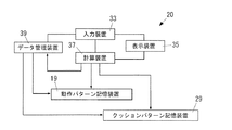
図3は、第1実施形態による、プレス機械10に設けられる動作設定装置20の構成を示す。動作設定装置20は、入力装置33、表示装置35および計算装置37を備える。入力装置33は、人が操作可能なキーボード、マウス、タッチパネルなどであり、この操作により動作パターンを定めることができるものである。動作パターンは、前記1プレスサイクル内の各時点毎に、スライド動作に関する動作速度を定めたものに基づいて求められる。
[First Embodiment]
(Configuration of operation setting device)
FIG. 3 shows a configuration of the
(時点の指定)
入力装置33を人が操作することで、前記動作速度を設定するための前記各時点を指定できるようになっている。即ち、入力装置33は、前記各時点を指定できるように人が操作可能である。また、入力装置33による前記各時点の指定は、前記昇降運動の昇降位置と前記回転運動の回転角のいずれでも指定できるようになっている。即ち、入力装置33は、前記各時点毎に、前記昇降運動の昇降位置と前記回転運動の回転角のいずれでも当該時点を指定できるように人が操作可能である。
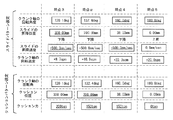
図4は、表示装置35により表示される入力画面の一例である。図4では、1プレスサイクル中の各時点(6つの時点)が指定されている。入力装置33により指定した時点の数値には、下線が引かれている。具体的には、時点1を、クランク軸11の回転運動の回転角θで0.0deg(即ち、スライド9の初期位置)と指定し、時点2を、スライド9の昇降位置yで450.00mmと指定し、時点3を、スライド9の昇降位置yで300.00mmと指定し、時点4を、クランク軸11の回転運動の回転角θで160.0degと指定し、時点5を、クランク軸11の回転運動の回転角θで180.0deg(即ち、スライド9の下死点)と指定し、時点6を、クランク軸11の回転運動の回転角θで360.0deg(即ち、スライド9の初期位置)と指定している。
クランク軸11の回転角θで指定した各時点1、4〜6については、この回転角θに対応するスライド9の昇降位置yが、計算装置37に自動計算されて図4のように表示される。一方、スライド9の昇降位置yで指定した各時点2、3については、この昇降位置yに対応する回転角θが、計算装置37に自動計算されて図4のように表示される。
(Specify time)
By operating the
FIG. 4 is an example of an input screen displayed by the
For each time point 1, 4 to 6 specified by the rotation angle θ of the
(動作速度の設定)
前記各時点を指定したら、指定した各時点毎に、入力装置33により動作速度を設定できる。即ち、入力装置33は、前記1プレスサイクル内の各時点毎に、前記動作パターンを定めるための動作速度を設定できるように、人が操作可能である。また、入力装置33により、前記各時点毎に、前記回転運動の回転速度と前記昇降運動の昇降速度のいずれかを任意に選択し、該選択した速度を該時点の動作速度として任意の値に設定できる。即ち、前記入力装置33は、前記各時点毎に、前記回転運動の回転速度と前記昇降運動の昇降速度のいずれかを任意に選択し、該選択した回転速度または昇降速度を該時点の動作速度として設定できるように人が操作可能である。
図4において、入力装置33により設定した動作速度の数値には、下線が引かれている。図4の例では、時点1の動作速度として、クランク軸11の回転速度20.0spm (stroke per minute)を設定し、時点2の動作速度として、クランク軸11の回転速度8.0spmを設定し、時点3の動作速度として、スライド9の昇降速度−500.0mm/secを設定し、時点4の動作速度として、スライド9の昇降速度−500.0mm/secを設定し、時点5の動作速度として、クランク軸11の回転速度20.0spm を設定し、時点6の動作速度として、クランク軸11の回転速度20.0spm を設定している。
クランク軸11の回転速度を設定した各時点1,2、5、6については、設定した回転速度に対応するスライド9の昇降速度が、計算装置37に自動計算されて図4のように表示される。一方、スライド9の回転速度を設定した各時点3、4については、設定した回転速度に対応するクランク軸11の回転速度が、計算装置37に自動計算されて図4のように表示される。
(Operation speed setting)
When each time point is designated, the operation speed can be set by the
In FIG. 4, the numerical value of the operation speed set by the
For each
(動作パターンの計算と表示)
入力装置33による入力データから動作パターンが計算される。即ち、計算装置37は、前記各時点毎に設定された前記動作速度に基づいて前記動作パターンを計算する。計算された動作パターンは、表示装置35により表示される。計算される前記動作パターンは、次の(A)と(B)の関係、または、次の(C)と(D)の関係である。
(A)経過時間または経過時間に比例して値が進行する変数
(B)前記経過時間または前記変数の各値における前記昇降運動の昇降位置、前記昇降運動の昇降速度、前記回転運動の回転角、もしくは、前記回転運動の回転速度
(C)前記昇降運動の昇降位置または前記回転運動の回転角
(D)前記昇降運動の昇降位置または前記回転運動の回転角の各値における前記昇降運動の昇降速度、もしくは、前記回転運動の回転速度
前記表示装置35は、次の(a),(b)を同時に表示してもよい。
(a)前記(A)と、前記(B)の前記昇降位置もしくは前記回転角との関係
(b)前記(A)と、前記(B)の前記昇降速度もしくは前記回転速度との関係
(Calculation and display of operation pattern)
An operation pattern is calculated from input data from the
(A) Elapsed time or a variable whose value advances in proportion to the elapsed time (B) Elevating position of the elevating movement, elevating speed of the elevating movement, or rotation angle of the rotating movement at the elapsed time or each value of the variable Or the rotational speed of the rotary motion (C) the lift position of the lift motion or the rotation angle of the rotary motion (D) the lift of the lift motion at each value of the lift position of the lift motion or the rotation angle of the rotary motion The speed or the rotational speed of the rotational motion The
(A) Relationship between (A) and the lift position or rotation angle of (B) (b) Relationship between (A) and the lift speed or rotation speed of (B)
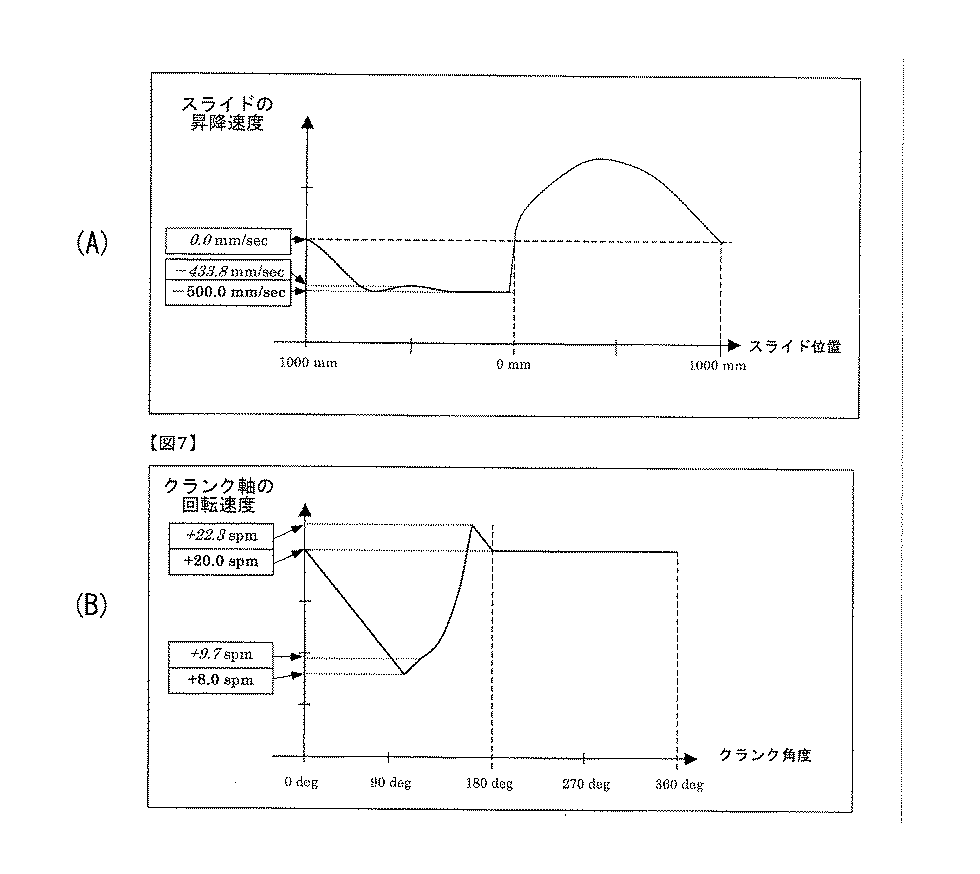
図5(A)〜(C)、図6(A)、(B)は、入力装置33による入力データに基づいて計算装置37が計算した動作パターンの例を示すグラフであり、表示装置35に表示される。図5(A)では、横軸が時間を示し縦軸がスライド9の昇降位置を示し、図5(B)では、横軸が時間を示し縦軸がスライド9の昇降速度を示し、図5(C)では、横軸が時間を示し縦軸がクランク軸11の回転速度を示している。図6(A)では、横軸がスライド9の昇降位置を示し縦軸がスライド9の昇降速度を示し、図6(B)では、横軸がクランク軸11の回転角を示し縦軸がクランク軸11の回転速度を示している。図5、図6に示すように、指定された各時点の間は、スライド9の昇降位置、昇降速度、回転速度が横軸の値(時間、スライドの昇降位置、クランク軸の回転角)に対して連続的に変化するように計算装置37に計算・補間される。図5(A)、(B)、(C)、図6(A)、(B)の動作パターンのうち、いずれか1つが計算装置37により計算され表示装置35に表示されてもよいし、複数または全部が計算装置37により計算され表示装置35に表示されてもよい。なお、図5(A)〜(C)において、横軸が時間を示しているが、時間の代わりに、1プレスサイクル中に時間経過に比例して値が進行する他の変数を使用してもよい。
FIGS. 5A to 5C, 6 </ b> A, and 6 </ b> B are graphs showing examples of operation patterns calculated by the
(動作パターンの記憶)
計算装置37は、スライド制御装置21の構成に合う動作パターンを、上述のように計算して動作パターン記憶装置19へ出力し動作パターン記憶装置19に記憶させる。計算装置37が複数の動作パターンを計算する場合には、計算された1または複数の動作パターンのうち、スライド制御装置21の構成に合うものが、計算装置37から動作パターン記憶装置19へ出力され、動作パターン記憶装置19に記憶される。即ち、スライド制御装置21が、1プレスサイクル中の各時点毎に、前記昇降運動の昇降位置を検出し、この検出値に基づいて、駆動モータ7への供給電力を制御する場合には、動作パターン記憶装置19に記憶される動作パターンは、前記経過時間または前記変数と、この経過時間または前記変数の各値における前記昇降運動の昇降位置との関係である。スライド制御装置21が、1プレスサイクル中の各時点毎に、前記昇降運動の昇降速度を検出し、この検出値に基づいて、駆動モータ7への供給電力を制御する場合には、動作パターン記憶装置19に記憶される動作パターンは、前記経過時間または前記変数と、この経過時間または前記変数の各値における前記昇降運動の昇降速度との関係である。スライド制御装置21が、1プレスサイクル中の各時点毎に、前記回転運動の回転角(クランク軸11または駆動モータ7の回転角)を検出し、この検出値に基づいて、駆動モータ7への供給電力を制御する場合には、動作パターン記憶装置19に記憶される動作パターンは、前記経過時間または前記変数と、この経過時間または前記変数の各値における前記回転運動の回転角(クランク軸11または駆動モータ7の回転角)との関係である。スライド制御装置21が、1プレスサイクル中の各時点毎に、前記回転運動の回転速度(クランク軸11または駆動モータ7の回転速度)を検出し、この検出値に基づいて、駆動モータ7への供給電力を制御する場合には、動作パターン記憶装置19に記憶される動作パターンは、前記経過時間または前記変数と、この経過時間または前記変数の各値における前記回転運動の回転速度(クランク軸11または駆動モータ7の回転速度)との関係である。
(Memory of operation pattern)
The
(動作パターンに基づく制御)
スライド制御装置21は、前記昇降運動の昇降位置、前記昇降運動の昇降速度、前記回転運動の回転角、もしくは、前記回転運動の回転速度を、動作位置または動作速度として検出するスライド動作用検出器(図示せず)を備える。スライド動作用検出器は、例えば、昇降位置を検出する場合には、リニアエンコーダであり、昇降速度を検出する場合には、リニアエンコーダによる位置検出値を時間微分するものであり、回転角を検出する場合には、ロータリーエンコーダであり、回転速度を検出する場合には、ロータリーエンコーダによる回転角検出値を時間微分するものであってよい。
スライド制御装置21は、1プレスサイクル中における経過時間の各値の時点で、スライド動作用検出器による検出値および動作パターンに基づいて、前記動作位置または動作速度が、動作パターンで定められた当該時点の前記動作位置または動作速度となるように、ドライバ7aを介して駆動モータ7への供給電力を制御する。この制御方式としては、例えば、フィードバック制御や、フィードバック制御とフィードフォワード制御の組み合わせなどがある。
(Control based on operation pattern)
The
The
第1実施形態によると、上述の本発明のプレス機械では、入力装置33は、人の操作により、前記回転運動の回転速度と前記昇降運動の昇降速度のいずれかを任意に選択し、該選択した前記回転速度または前記昇降速度を該時点の動作速度として設定できように構成され、計算装置37は、入力装置33により前記各時点毎に設定された前記動作速度に基づいて前記動作パターンを計算するので、ある時点では前記回転速度を動作速度として設定し、別の時点では前記昇降速度を動作速度として設定したい場合に回転速度と昇降速度との間で単位変換する計算を、ユーザが行う必要がなくなる。従って、プレス機械調整においてユーザにかかる負担が大幅に低減される。
特に、本発明は次の場合に非常に有効である。1対の金型が被加工物1に接触してプレス成形を行っているプレス成形期間については、スライド9の昇降速度を調整することで被加工物1の成形性を調整できるので、プレス成形期間では前記昇降速度を直接設定したい場合がある。一方、スライド9が下死点に到達した後は、スライド9をできるだけ早く上昇させたいため、前記回転運動の最大回転速度を直接設定したい場合がある。これについて、本発明は、プレス成形期間では前記昇降速度を直接設定することで成形性を調整し、これと同時に、スライド9が下死点に到達した以降では回転運動の最大回転速度を直接設定することを可能にし、非常に有効である。
According to the first embodiment, in the press machine of the present invention described above, the
In particular, the present invention is very effective in the following cases. For the press forming period in which the pair of molds are in contact with the workpiece 1 and press forming is performed, the formability of the workpiece 1 can be adjusted by adjusting the lifting speed of the
(スライドの停止)
上述の第1実施形態において、プレス成形中の任意の前記昇降位置(例えば下死点)でスライド9を停止させる設定も可能である。この場合、入力装置33を人が操作することで、スライド9を停止させたい区間の開始時点と終了時点とを指定することができる。ただし、入力装置33を人が操作することで、開始時点から終了時点までの経過時間も合わせて設定する。この開始時点と終了時点の各々は、前記昇降運動の昇降位置と前記回転運動の回転角のいずれによっても指定できる。なお、停止しているので、開始時点と終了時点は同じである。また、入力装置33を人が操作することで、この開始時点と終了時点の各々について、前記回転運動の回転速度と前記昇降運動の昇降速度のいずれかを任意に選択し、該選択した前記回転速度または前記昇降速度を該時点の動作速度としてゼロに設定する。この場合における他の点は、上述した内容(即ち、(動作設定装置の構成)〜(動作パターンに基づく制御)までの内容)と、同じであってよい。即ち、前記開始時点と終了時点を上述した各時点と同様に扱うことができる。
(Stop slide)
In the first embodiment described above, it is also possible to set the
(駆動モータの逆回転)
また、プレス成形中(スライド9の下死点を含む)の所望の時点から駆動モータ7(サーボモータ)を逆回転させてスライド9を上昇させる設定も可能である。この場合、入力装置33を人が操作することで、駆動モータ7を逆回転させたい区間の開始時点と終了時点とを指定することができる。この開始時点と終了時点の各々は、前記昇降運動の昇降位置と前記回転運動の回転角のいずれによっても指定できる。さらに、入力装置33を人が操作することで、この開始時点と終了時点の各々について、前記回転運動の回転速度と前記昇降運動の昇降速度のいずれかを任意に選択し、該選択した前記回転速度または前記昇降速度を該時点の動作速度として任意の値に設定できる。この場合における他の点は、上述した内容(即ち、(動作設定装置の構成)〜(動作パターンに基づく制御)までの内容)と同じであってよい。即ち、前記開始時点と終了時点を上述の各時点と同様に扱うことができる。なお、前記終了時点以降の時点については、上述した内容と同じである。
(Reverse rotation of drive motor)
Further, it is possible to set the
このように、プレス成形中の任意の前記昇降位置でスライド9を停止させる設定や、プレス成形中の所望の時点から駆動モータ7を逆回転させてスライド9を上昇させる設定が可能であるので、種々の運転形態に対応することが可能となる。従って、プレスを停止させたり逆転させたりする場合のプレス機械調整において、ユーザにかかる負担が大幅に低減される。
また、駆動モータ7の逆回転により、成形中に一旦上金型3を被加工物1から引き離す動作を行うことにより成形性が向上することがある。
さらに、成形完了後に駆動モータ7を逆回転させることで、下死点にあるスライド9を上昇させ、下金型5を切り替えて、穴あけや切り落としなどの追加工を行うことが可能となる。
Thus, it is possible to set the
Further, by reverse rotation of the
Further, by reversely rotating the
入力装置33は、前記各時点毎に、前記昇降運動の昇降位置と前記回転運動の回転角のいずれでも当該時点を指定できるように人が操作可能であるので、ある時点は前記昇降運動の位置で指定し、別の時点は前記回転運動の回転角で指定したい場合に、前記昇降運動の位置と前記回転運動の回転角との間で単位変換する計算をユーザが行う必要がなくなる。従って、プレス機械調整においてユーザにかかる負担が大幅に低減される。
The
上述の動作パターンを表示装置35により表示できるので、動作パターンを表示装置35上で視覚的に確認できる。従って、動作パターンの設定ミスを防止でき、動作パターンの設定調整に便利である。
Since the above-described operation pattern can be displayed on the
表示装置35が前記(a),(b)を同時に表示することで、1プレスサイクルの全体にわたって、前記昇降位置もしくは前記回転角の時間変化を確認できるだけでなく、これと同時に、前記昇降速度もしくは前記回転速度の時間変化も確認できる。
The
[第2実施形態]
本発明の第2実施形態による動作設定装置20は、第1実施形態の構成と以下で説明する構成とを有する。
[Second Embodiment]
The
上述のように、駆動モータ7としてサーボモータを使用する場合には、スライド9の動作速度を各時点毎に自在に設定できる。そのため、第2実施形態では、スライド動作が変化する各時点毎に、クッション力を設定できるようにする。
As described above, when a servo motor is used as the
第2実施形態では、入力装置33は、前記1プレスサイクル内の各時点毎に、前記クッションパターンを定めるためのクッション力を設定できるように、人が操作可能である。
In the second embodiment, the
(クッション力の設定)
図7は、表示装置35により表示される入力画面である。図7の「クッションパターン設定」において、下線が引いてある数値が、入力装置33により設定した値である。図7の例では、第1実施形態の図4で指定された時点毎に、クッション力を設定している。具体的には、時点3のクッション力に200tonを設定し、時点4のクッション力に200tonを設定している。
時点1、2はプレス成形中ではないので、時点1、2のクッション力は自動的に0tonに設定されている。代わりに、時点1、2のクッション位置(即ち、ブランクホルダ25aの待機高さ)を、人が入力装置33を操作して設定可能である。この例では、時点1、2のクッション位置を300.00mmに設定している。また、図7には、図4の時点5、6が示されていないが、時点5、6もプレス成形中ではないので、時点5、6のクッション力も自動的に0tonに設定されている。なお、プレス成形中以外の各時点においても、人が入力装置33を操作してクッション力を設定してもよい。また、プレス成形中(例えば時点3、4)は、スライド9と可動部25が一体となって下降するので、クッション位置は、スライド9の昇降位置に等しい。
(Cushion force setting)
FIG. 7 is an input screen displayed by the
Since the time points 1 and 2 are not in press forming, the cushion force at the time points 1 and 2 is automatically set to 0 ton. Instead, the person can operate the
図8は、図7の設定に基づいて決定されるダイクッション装置23のクッションパターンを示すグラフであり、表示装置35に表示される。図8の上側のグラフは、時間に対するクッション位置(即ち、ブランクホルダ25aの高さ)を示している。図8の上側のグラフにおいて、時間に対するスライド9の昇降位置も示している。図8の下側のグラフは、時間に対するクッション力を示している。即ち、図8の下側のグラフは、図7の設定に基づいて計算装置37により計算されるクッションパターンを示すグラフである。
図8の下側のグラフから分かるように、この例では、各時点は、クッション力が不連続的に切り替わる時点となっている。このように、各時点に設定されたクッション力は、当該時点から当該時点の直後に指定された時点まで維持されるようになっている。
FIG. 8 is a graph showing a cushion pattern of the
As can be seen from the lower graph in FIG. 8, in this example, each time point is a time point when the cushion force switches discontinuously. Thus, the cushioning force set at each time point is maintained from the time point to the time point specified immediately after the time point.
また、スライド9の動作速度設定時に指定した時点以外の時点を新たに指定し、この新たな時点にクッション力を設定するようにしてもよい。
図9は、新たな時点を指定した場合の入力画面である。図9では、第1実施形態の図4で指定された時点1〜6以外に、時点3と時点4の間に新たな時点αを指定している。新たな時点の指定方法は、第1実施形態と同じであり、入力装置33を人が操作することで行われる。図9では、新たな時点αを、「クッションパターン設定」のクッション位置(即ち、スライド9の昇降位置)で指定している。また、図9の「スライドパターン設定」において、時点αでは、計算装置37により計算された前記動作パターンに基づいて各値が表示されている。
この新たな時点αにもクッション力を設定することができる。この設定も、上述と同様に入力装置33を人が操作することで行われる。図9の「クッションパターン設定」において、下線が引いてある数値が、入力装置33により設定した値である。具体的には、図9の例では、時点3のクッション力を200tonに設定し、時点αのクッション力を150tonに設定し、時点4のクッション力を150tonに設定し、時点5のクッション力を0tonに設定し、図示しない他の時点1、2、6のクッション力も0tonに設定している。
Alternatively, a time point other than the time point specified when the operation speed of the
FIG. 9 shows an input screen when a new time point is designated. In FIG. 9, a new time point α is specified between the time points 3 and 4 in addition to the time points 1 to 6 specified in FIG. 4 of the first embodiment. The new time designation method is the same as in the first embodiment, and is performed by a person operating the
The cushioning force can also be set at this new time α. This setting is also performed by a person operating the
図10は、図9の設定に基づいて決定されるダイクッション装置23の動作を示すグラフであり、表示装置35に表示される。図10の上側のグラフは、時間に対するクッション位置を示している。図10の上側のグラフにおいて、時間に対するスライド9の昇降位置も示している。図10の下側のグラフは、時間に対するクッション力を示している。即ち、図10の下側のグラフは、図9の設定に基づいて計算装置37により計算されるクッションパターンを示すグラフである。
図10の下側のグラフから分かるように、この例では、各時点は、クッション力が不連続的に切り替わる時点となっている。従って、各時点に設定されたクッション力は、当該時点から当該時点の直後に指定された時点まで維持されるようになっている。
FIG. 10 is a graph showing the operation of the
As can be seen from the lower graph in FIG. 10, in this example, each time point is a time point when the cushion force switches discontinuously. Therefore, the cushioning force set at each time point is maintained from the time point to a time point specified immediately after the time point.
(クッションパターンに基づく制御)
クッション制御装置31は、クッション力を検出するクッション用検出器を備える。クッション制御装置31は、1プレスサイクル中における経過時間の各値の時点で、クッション用検出器によるクッション力の検出値およびクッションパターンに基づいて、クッション力が、クッションパターンで定められた当該時点のクッション力となるように、駆動装置27の制御対象部27aを制御する。この制御方式としては、例えば、フィードバック制御や、フィードバック制御とフィードフォワード制御の組み合わせなどがある。
図1の例のように駆動装置27が油圧シリンダによるものである場合、制御対象部27aは、サーボ弁であり、クッション用検出器は、例えば、シリンダの上室の油圧と下室の油圧を検出し、これら検出値からクッション力を検出する。
(Control based on cushion pattern)
The
When the driving
第2実施形態によると、入力装置33は、前記1プレスサイクル内の各時点毎に、前記クッションパターンを定めるためのクッション力を設定できるように、人が操作可能であるので、スライド9の動作パターンに合わせたクッションパターンを簡単に設定できる。従って、スライド9の動作パターンに合わせたクッションパターン設定・調整の複雑さを解消でき、ユーザによるクッション力の設定・調整負担が大幅に低減される。
例えば、表示装置35に表示されたスライドの前記動作パターンを確認しながら、各時点毎にクッション力を設定でき、ユーザによるクッション力調整負担が大幅に低減される。
According to the second embodiment, the
For example, while confirming the operation pattern of the slide displayed on the
[第3実施形態]
本発明の第3実施形態による動作設定装置20は、第1実施形態または第2実施形態の構成と以下で説明する構成とを有する。
[Third Embodiment]
The
プレス機械10では、上金型3および下金型5を別の種類の上金型3および下金型5に変更可能である。この場合、動作設定装置20は、上金型3および下金型5毎に、上金型3および下金型5を示す識別情報と関連付けて前記動作パターンとクッションパターンを記憶するデータ管理装置39を備える。
In the
前記識別情報をデータ管理装置39に入力することで、該識別情報と関連付けられた前記動作パターンがスライド制御装置21に自動的に使用され、該識別情報と関連付けられた前記クッションパターンがクッション制御装置31に自動的に使用されるようになっている。この入力は、入力装置33または別の入力手段を人が操作することでなされてもよいし、識別情報を識別情報保持手段(例えばICタグ)から読み取るなど他の手段によりなされてもよい。
データ管理装置39は、前記動作パターン記憶装置19とクッションパターン記憶装置29とから構成されていてもよいし、図11のように動作パターン記憶装置19およびクッションパターン記憶装置29とは別の装置であってもよい。データ管理装置39が、動作パターン記憶装置19およびクッションパターン記憶装置29とは別の装置である場合には、プレス機械10に取り付けている第1の上金型3および下金型5をクッションパターンを以前に求めた第2の上金型3および下金型5に変更する際には、第2の上金型3および下金型5を示す前記識別情報がデータ管理装置39に入力されることで、該識別情報と関連付けられた前記動作パターンが、自動的に動作パターン記憶装置19へ出力され動作パターン記憶装置19に記憶され、該識別情報と関連付けられた前記クッションパターンが、自動的にクッションパターン記憶装置29へ出力されクッションパターン記憶装置29に記憶される。
By inputting the identification information to the
The
第3実施形態によると、前記識別情報をデータ管理装置39に入力することで、該識別情報と関連付けられた前記動作パターンがスライド制御装置21に使用され、該識別情報と関連付けられた前記クッションパターンがクッション制御装置31に使用されるようになっているので、金型変更時のプレス機械動作設定において、ユーザにかかる負担が大幅に低減される。
According to the third embodiment, by inputting the identification information to the
本発明は上述した実施の形態に限定されず、本発明の要旨を逸脱しない範囲で種々変更を加え得ることは勿論である。 The present invention is not limited to the above-described embodiment, and various changes can be made without departing from the scope of the present invention.
例えば、上述の第1〜第3実施形態では、駆動モータ7による回転運動の回転角、回転速度として、主に、クランク軸11の回転角、回転速度を指定または設定するように説明したが、駆動モータ7による回転運動の回転角、回転速度として、駆動モータ7の回転角、回転速度を指定または設定してもよい。
For example, in the first to third embodiments described above, it has been described that the rotation angle and rotation speed of the
上述の第1〜第3実施形態では、スライド9の動作速度またはクッション力を各時点毎に設定したが、この設定後に、スライド9の動作速度またはクッション力を各時点毎に変更することもできる。この変更は、第1〜第3実施形態と同様に入力装置33の操作により行うことができる。この場合も、図4、図7、図9と同じ画面が表示装置35に表示されてよい。
In the first to third embodiments described above, the operation speed or cushion force of the
入力装置33により指定できる時点の数は任意であってよい。
The number of time points that can be specified by the
上述の第2実施形態では、計算装置37は、各時点毎に設定されたクッション力に基づいて、各時点でクッション力が不連続的に変化するようにクッションパターンを決定・計算したが、経過時間に対し連続的にクッション力が変化するようにクッションパターンを計算してもよい。
In the second embodiment described above, the
駆動装置27は、油圧シリンダを用いた装置の代わりに、サーボモータの回転駆動力を上向きのクッション力に変換する装置であってもよい。この場合、クッション制御装置31は、サーボモータに電力を供給するドライバを制御対象部27aとして制御するものであり、上述のクッション用検出器は、駆動装置27がクッションプレート25cを押圧する箇所に設けられた歪みゲージの歪み検出値に基づいて、クッション力を検出するものであってよい。
The
クッション制御装置31は、1プレスサイクル中において、スライド9が可動部25に力を作用させていない期間では、クッション位置検出値に基づいてクッション位置を直接制御する位置制御を行い、スライド9が可動部25に力を作用させているクッション作動期間では、クッション力検出値に基づいてクッション力を直接制御する荷重制御を行うものであってもよい。この場合でも、本発明では、スライド9の動作に合わせて、クッション作動期間内の各時点で、クッション力を容易に設定・変更することができる。
The
上述では、駆動モータ7による回転運動の回転角、回転速度を、主にクランク軸11の回転角、回転速度として説明したが、駆動モータ7による回転運動の回転角、回転速度は、駆動モータ7の回転角、回転速度としてもよい。
In the above description, the rotation angle and rotation speed of the rotation motion by the
1 被加工物、3 上金型、5 下金型、7 駆動モータ、7a ドライバ、9 スライド、10 プレス機械、11 変換機構(クランク軸)、13 ピニオン、15 メインギヤ、17 コネクティングロッド、19 動作パターン記憶装置、20 動作設定装置、21 スライド制御装置、23 ダイクッション装置、25 可動部、25a ブランクホルダ、25b クッションピン、25c クッションプレート、27 駆動装置、27a 制御対象部、29 クッションパターン記憶装置、31 クッション制御装置、33 入力装置、35 表示装置、37 計算装置、39 データ管理装置、 1 Workpiece, 3 Upper mold, 5 Lower mold, 7 Drive motor, 7a Driver, 9 Slide, 10 Press machine, 11 Conversion mechanism (Crankshaft), 13 Pinion, 15 Main gear, 17 Connecting rod, 19 Operation pattern Storage device, 20 Operation setting device, 21 Slide control device, 23 Die cushion device, 25 Movable part, 25a Blank holder, 25b Cushion pin, 25c Cushion plate, 27 Drive device, 27a Control target part, 29 Cushion pattern storage device, 31 Cushion control device, 33 input device, 35 display device, 37 calculation device, 39 data management device,
Claims (6)
前記上金型を駆動するための駆動モータと、
前記駆動モータによる回転運動を、前記上金型が固定されたスライドの昇降運動に変換する変換機構と、を備えるプレス機械であって、
被加工物を1回プレス成形するための1プレスサイクルにおける前記スライドの動作パターンを記憶する動作パターン記憶装置と、
前記動作パターンに基づいて前記駆動モータを制御するスライド制御装置と、
前記1プレスサイクル内の各時点毎に、前記動作パターンを定めるための動作速度を設定できるように、人が操作可能な入力装置と、を備え、
前記入力装置は、前記各時点毎に、前記回転運動の回転速度と前記昇降運動の昇降速度のいずれかを任意に選択し、該選択した前記回転速度または前記昇降速度を該時点の動作速度として所望の値に設定できるように人が操作可能であり、
前記入力装置により前記各時点毎に設定された前記動作速度に基づいて前記動作パターンを計算する計算装置を、さらに備える、ことを特徴とするプレス機械。 An upper mold and a lower mold that are press-molded with a workpiece sandwiched therebetween;
A drive motor for driving the upper mold;
A conversion mechanism that converts the rotational movement by the drive motor into the up-and-down movement of the slide to which the upper mold is fixed, and a press machine comprising:
An operation pattern storage device for storing an operation pattern of the slide in one press cycle for press-molding a workpiece once;
A slide control device for controlling the drive motor based on the operation pattern;
An input device that can be operated by a person so that an operation speed for determining the operation pattern can be set for each time point in the one press cycle,
The input device arbitrarily selects either the rotational speed of the rotary motion or the vertical speed of the lifting motion at each time point, and uses the selected rotational speed or the lifting speed as the operation speed at the time point. It can be operated by a person so that it can be set to the desired value.
A press machine, further comprising a calculation device that calculates the operation pattern based on the operation speed set for each time point by the input device.
前記入力装置は、前記各時点毎に、前記昇降運動の昇降位置と前記回転運動の回転角のいずれでも当該時点を指定できるように人が操作可能である、ことを特徴とする請求項1に記載のプレス機械。 The input device is operable by a person so that each time point can be specified,
The input device can be operated by a person so that at each time point, the time point can be designated by either the lift position of the lift motion or the rotation angle of the rotary motion. The press machine described.
前記動作パターンは、次の(A)と(B)の関係、または、次の(C)と(D)の関係である、ことを特徴とする請求項1または2に記載のプレス機械。
(A)経過時間または経過時間に比例して値が進行する変数
(B)前記経過時間または前記変数の各値における前記昇降運動の昇降位置、前記昇降運動の昇降速度、前記回転運動の回転角、もしくは、前記回転運動の回転速度
(C)前記昇降運動の昇降位置または前記回転運動の回転角
(D)前記昇降運動の昇降位置または前記回転運動の回転角の各値における前記昇降運動の昇降速度、もしくは、前記回転運動の回転速度 A display device for displaying the operation pattern calculated by the calculation device;
The press machine according to claim 1 or 2, wherein the operation pattern is the following relationship (A) and (B) or the following relationship (C) and (D).
(A) Elapsed time or a variable whose value advances in proportion to the elapsed time (B) Elevating position of the elevating movement, elevating speed of the elevating movement, or rotation angle of the rotating movement at the elapsed time or each value of the variable Or the rotational speed of the rotary motion (C) the lift position of the lift motion or the rotation angle of the rotary motion (D) the lift of the lift motion at each value of the lift position of the lift motion or the rotation angle of the rotary motion Speed or rotational speed of the rotary motion
(a)前記(A)と、前記(B)の前記昇降位置もしくは前記回転角との関係
(b)前記(A)と、前記(B)の前記昇降速度もしくは前記回転速度との関係 The press machine according to claim 3, wherein the display device displays the following (a) and (b) simultaneously.
(A) Relationship between (A) and the lift position or rotation angle of (B) (b) Relationship between (A) and the lift speed or rotation speed of (B)
このダイクッション装置は
上金型と下金型との間で被加工物がプレス成形されるプレス成形時に、被加工物を上金型との間に挟みながら下降する可動部と、
この可動部にクッション力を付与する駆動装置と、
前記1プレスサイクルにおける前記クッション力のクッションパターンを記憶するクッションパターン記憶装置と、
前記クッションパターンに基づいて前記駆動装置を制御するクッション制御装置と、を備え、
前記入力装置は、前記1プレスサイクル内の各時点毎に、前記クッションパターンを定めるためのクッション力を設定できるように、人が操作可能であり、
前記クッションパターンを定める当該各時点は、前記動作速度の設定に関する前記各時点のいずれか、または、他の任意の時点である、ことを特徴とする請求項1〜4のいずれか一項に記載のプレス機械。 Equipped with a die cushion device,
This die cushion device has a movable part that descends while sandwiching the workpiece between the upper die and the upper die when the workpiece is press-molded between the upper die and the lower die,
A driving device for applying a cushioning force to the movable part;
A cushion pattern storage device for storing a cushion pattern of the cushion force in the one press cycle;
A cushion control device that controls the drive device based on the cushion pattern,
The input device is operable by a person so that a cushion force for determining the cushion pattern can be set at each time point in the one press cycle,
5. The time points for defining the cushion pattern are any one of the time points related to the setting of the operation speed, or any other time point, according to claim 1. Press machine.
前記上金型および下金型毎に、該前記上金型および下金型を示す識別情報と関連付けて前記動作パターンを記憶するデータ管理装置を備え、
前記識別情報をデータ管理装置に入力ことで、該識別情報と関連付けられた前記動作パターンが前記制御装置に使用されるようになっている、ことを特徴とする請求項1〜5のいずれか一項に記載のプレス機械。 The upper die and the lower die attached to the press machine can be changed to different upper die and lower die,
A data management device that stores the operation pattern in association with identification information indicating the upper mold and the lower mold for each of the upper mold and the lower mold,
6. The operation pattern associated with the identification information is used by the control device by inputting the identification information to a data management device. The press machine according to item.
Priority Applications (1)
| Application Number | Priority Date | Filing Date | Title |
|---|---|---|---|
| JP2008249947A JP5413795B2 (en) | 2008-09-29 | 2008-09-29 | Press machine |
Applications Claiming Priority (1)
| Application Number | Priority Date | Filing Date | Title |
|---|---|---|---|
| JP2008249947A JP5413795B2 (en) | 2008-09-29 | 2008-09-29 | Press machine |
Publications (2)
| Publication Number | Publication Date |
|---|---|
| JP2010075987A true JP2010075987A (en) | 2010-04-08 |
| JP5413795B2 JP5413795B2 (en) | 2014-02-12 |
Family
ID=42207037
Family Applications (1)
| Application Number | Title | Priority Date | Filing Date |
|---|---|---|---|
| JP2008249947A Expired - Fee Related JP5413795B2 (en) | 2008-09-29 | 2008-09-29 | Press machine |
Country Status (1)
| Country | Link |
|---|---|
| JP (1) | JP5413795B2 (en) |
Cited By (4)
| Publication number | Priority date | Publication date | Assignee | Title |
|---|---|---|---|---|
| JP2012000637A (en) * | 2010-06-16 | 2012-01-05 | Ihi Corp | Die cushion control device |
| JP2012000638A (en) * | 2010-06-16 | 2012-01-05 | Ihi Corp | Die cushion control device |
| JP2017070974A (en) * | 2015-10-06 | 2017-04-13 | トヨタ自動車株式会社 | Control method for powder molding device |
| JP7459188B2 (en) | 2022-08-19 | 2024-04-01 | 株式会社クボタ | Correction device and correction method |
Citations (4)
| Publication number | Priority date | Publication date | Assignee | Title |
|---|---|---|---|---|
| JPH10277798A (en) * | 1997-03-31 | 1998-10-20 | Komatsu Ltd | Device and method for controlling motion of servo press |
| JP2004001016A (en) * | 2002-05-30 | 2004-01-08 | Aida Eng Ltd | Press machine |
| JP2004058152A (en) * | 2002-06-05 | 2004-02-26 | Komatsu Ltd | Setting method and displaying method for slide position of servo press, synchronizing method with external peripheral equipment, and its control device |
| JP2008006459A (en) * | 2006-06-28 | 2008-01-17 | Ihi Corp | Press machine |
-
2008
- 2008-09-29 JP JP2008249947A patent/JP5413795B2/en not_active Expired - Fee Related
Patent Citations (4)
| Publication number | Priority date | Publication date | Assignee | Title |
|---|---|---|---|---|
| JPH10277798A (en) * | 1997-03-31 | 1998-10-20 | Komatsu Ltd | Device and method for controlling motion of servo press |
| JP2004001016A (en) * | 2002-05-30 | 2004-01-08 | Aida Eng Ltd | Press machine |
| JP2004058152A (en) * | 2002-06-05 | 2004-02-26 | Komatsu Ltd | Setting method and displaying method for slide position of servo press, synchronizing method with external peripheral equipment, and its control device |
| JP2008006459A (en) * | 2006-06-28 | 2008-01-17 | Ihi Corp | Press machine |
Cited By (4)
| Publication number | Priority date | Publication date | Assignee | Title |
|---|---|---|---|---|
| JP2012000637A (en) * | 2010-06-16 | 2012-01-05 | Ihi Corp | Die cushion control device |
| JP2012000638A (en) * | 2010-06-16 | 2012-01-05 | Ihi Corp | Die cushion control device |
| JP2017070974A (en) * | 2015-10-06 | 2017-04-13 | トヨタ自動車株式会社 | Control method for powder molding device |
| JP7459188B2 (en) | 2022-08-19 | 2024-04-01 | 株式会社クボタ | Correction device and correction method |
Also Published As
| Publication number | Publication date |
|---|---|
| JP5413795B2 (en) | 2014-02-12 |
Similar Documents
| Publication | Publication Date | Title |
|---|---|---|
| JP4587752B2 (en) | Control device and control method of hybrid control servo press | |
| JP5413795B2 (en) | Press machine | |
| US7926317B2 (en) | Pressing machine, crank pressing machine, and vibration processing method in these machines | |
| US10081150B2 (en) | Press machine and method for adjusting slide position thereof | |
| JP2004160529A (en) | Double acting hydraulic press | |
| JP2007222926A (en) | Apparatus for controlling cushion load, and press machine having the same | |
| JP3929362B2 (en) | Servo press, processing method using the same, and control method thereof | |
| JP5115175B2 (en) | Control device and control method of die cushion device | |
| CN102259438A (en) | Punching apparatus and control method of punching apparatus | |
| JPH10277798A (en) | Device and method for controlling motion of servo press | |
| JP5354240B2 (en) | Servo press and its operation control method | |
| JP2006255740A (en) | Fine blanking press | |
| WO1998043802A1 (en) | Multi-stage motion control device of servo press and control method therefor | |
| JP2010253540A (en) | Die cushion device and cushion force controlling method for the same | |
| KR20100009775A (en) | Motion data setting apparatus of press machine and method of the same | |
| JP5659572B2 (en) | Die cushion control device | |
| JP4824463B2 (en) | Control device for die cushion mechanism | |
| JP3807495B2 (en) | Motion setting method of electric servo press | |
| JP5659571B2 (en) | Die cushion control device | |
| JP3396754B2 (en) | Press forming machine for ceramic products | |
| JP4171435B2 (en) | Control method and control device for mechanical press | |
| JP2003154497A (en) | Press apparatus | |
| JP2013136060A (en) | Press machine and control method of press machine | |
| JPH1133798A (en) | Device and method for setting molding condition of servo press | |
| JP2009214159A (en) | Press machine, and control device therefor |
Legal Events
| Date | Code | Title | Description |
|---|---|---|---|
| A621 | Written request for application examination |
Free format text: JAPANESE INTERMEDIATE CODE: A621 Effective date: 20110809 |
|
| A977 | Report on retrieval |
Free format text: JAPANESE INTERMEDIATE CODE: A971007 Effective date: 20130221 |
|
| A131 | Notification of reasons for refusal |
Free format text: JAPANESE INTERMEDIATE CODE: A131 Effective date: 20130225 |
|
| A521 | Written amendment |
Free format text: JAPANESE INTERMEDIATE CODE: A523 Effective date: 20130425 |
|
| A01 | Written decision to grant a patent or to grant a registration (utility model) |
Free format text: JAPANESE INTERMEDIATE CODE: A01 Effective date: 20131021 |
|
| A61 | First payment of annual fees (during grant procedure) |
Free format text: JAPANESE INTERMEDIATE CODE: A61 Effective date: 20131103 |
|
| LAPS | Cancellation because of no payment of annual fees |