JP2010073969A - レーザユニットの取付位置調整用治具 - Google Patents
レーザユニットの取付位置調整用治具 Download PDFInfo
- Publication number
- JP2010073969A JP2010073969A JP2008241026A JP2008241026A JP2010073969A JP 2010073969 A JP2010073969 A JP 2010073969A JP 2008241026 A JP2008241026 A JP 2008241026A JP 2008241026 A JP2008241026 A JP 2008241026A JP 2010073969 A JP2010073969 A JP 2010073969A
- Authority
- JP
- Japan
- Prior art keywords
- laser
- laser unit
- substrate
- mounting position
- unit
- Prior art date
- Legal status (The legal status is an assumption and is not a legal conclusion. Google has not performed a legal analysis and makes no representation as to the accuracy of the status listed.)
- Granted
Links
Images


Landscapes
- Supply And Installment Of Electrical Components (AREA)
Abstract
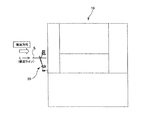
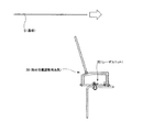
【解決手段】表面実装装置において搬送ラインに沿って搬送される基板Sに、下方からレーザを照射して該基板の裏面に付設されているバーコードを読み取るレーザユニット20の取付位置を調整する際に使用するレーザユニットの取付位置調整用治具30であって、前記レーザユニットを、所定の位置関係で被う着脱可能なカバー32と、該カバーの搬送ライン側に固定され、前記レーザユニットの基板裏面におけるレーザ照射範囲に対応する範囲を指示する指示部34A、34Bと、を備えている。
【選択図】図4
Description
12…壁部
14…支持部材
20…レーザユニット
30…取付位置調整用治具
32…カバー
34…軸部材
36…LED(可視光光源)
38…拡散防止パイプ
S…基板
L…搬送ライン
R…レーザ照射範囲
r…部分範囲
Claims (3)
- 表面実装装置において搬送ラインに沿って搬送される基板に、下方からレーザを照射して該基板の裏面に付設されているバーコードを読み取るレーザユニットの取付位置を調整する際に使用するレーザユニットの取付位置調整用治具であって、
前記レーザユニットを、所定の位置関係で被う着脱可能なカバーと、
該カバーの搬送ライン側に固定され、前記レーザユニットの基板裏面におけるレーザ照射範囲に対応する範囲を指示する指示部と、を備えたことを特徴とするレーザユニットの取付位置調整用治具。 - 前記指示部が、前記レーザ照射範囲に対応する範囲の少なくとも両端を規定する軸部材であることを特徴とする請求項1に記載のレーザユニットの取付位置調整用治具。
- 前記指示部が、前記レーザ照射範囲に対応する範囲の少なくとも両端を規定する、可視光を発生する光源と、該可視光を基板裏面に導く拡散防止パイプと、を含むことを特徴とする請求項1に記載のレーザユニットの取付位置調整用治具。
Priority Applications (1)
| Application Number | Priority Date | Filing Date | Title |
|---|---|---|---|
| JP2008241026A JP5208639B2 (ja) | 2008-09-19 | 2008-09-19 | レーザユニットの取付位置調整用治具 |
Applications Claiming Priority (1)
| Application Number | Priority Date | Filing Date | Title |
|---|---|---|---|
| JP2008241026A JP5208639B2 (ja) | 2008-09-19 | 2008-09-19 | レーザユニットの取付位置調整用治具 |
Publications (2)
| Publication Number | Publication Date |
|---|---|
| JP2010073969A true JP2010073969A (ja) | 2010-04-02 |
| JP5208639B2 JP5208639B2 (ja) | 2013-06-12 |
Family
ID=42205475
Family Applications (1)
| Application Number | Title | Priority Date | Filing Date |
|---|---|---|---|
| JP2008241026A Expired - Fee Related JP5208639B2 (ja) | 2008-09-19 | 2008-09-19 | レーザユニットの取付位置調整用治具 |
Country Status (1)
| Country | Link |
|---|---|
| JP (1) | JP5208639B2 (ja) |
Citations (3)
| Publication number | Priority date | Publication date | Assignee | Title |
|---|---|---|---|---|
| JPS6399600A (ja) * | 1986-10-15 | 1988-04-30 | 三菱電機株式会社 | 半導体製造装置 |
| JPH073037U (ja) * | 1994-06-08 | 1995-01-17 | 富士電機株式会社 | 情報読取装置 |
| JPH0981662A (ja) * | 1995-09-18 | 1997-03-28 | Fujitsu Kiden Ltd | ガンスキャナ |
-
2008
- 2008-09-19 JP JP2008241026A patent/JP5208639B2/ja not_active Expired - Fee Related
Patent Citations (3)
| Publication number | Priority date | Publication date | Assignee | Title |
|---|---|---|---|---|
| JPS6399600A (ja) * | 1986-10-15 | 1988-04-30 | 三菱電機株式会社 | 半導体製造装置 |
| JPH073037U (ja) * | 1994-06-08 | 1995-01-17 | 富士電機株式会社 | 情報読取装置 |
| JPH0981662A (ja) * | 1995-09-18 | 1997-03-28 | Fujitsu Kiden Ltd | ガンスキャナ |
Also Published As
| Publication number | Publication date |
|---|---|
| JP5208639B2 (ja) | 2013-06-12 |
Similar Documents
| Publication | Publication Date | Title |
|---|---|---|
| JP6103800B2 (ja) | 部品実装機 | |
| KR102437902B1 (ko) | 레이저 가공 장치 | |
| KR20190125168A (ko) | 레이저 광축 확인용 지그 유닛 및 지그 | |
| KR101561895B1 (ko) | 레이저 장치와 워크피스 표면에 레이저를 조사하는 방법 | |
| CN109690417B (zh) | 用于在载体上安装印刷版的系统和方法 | |
| JP2008233638A (ja) | 描画装置および描画方法 | |
| US9427826B2 (en) | Hand-guided marking system | |
| JP5208639B2 (ja) | レーザユニットの取付位置調整用治具 | |
| JP2009539126A (ja) | 光学式プリンタに関する改良 | |
| JP7013066B2 (ja) | キャリブレーションシステム及び描画装置 | |
| US7772776B2 (en) | Display device with panel and chassis base aligned | |
| DE69827091D1 (de) | Blattzuführverfahren für ein Bilderzeugungsgerät, bei dem die Blatttransportbahn einer Blattkassette als Teil der Blatttransportbahn einer anderen Blattkassette dient | |
| JP2006198725A (ja) | クランプ装置及び画像形成装置 | |
| JP5705729B2 (ja) | 番号印刷機の支持ディスクと番号印刷ユニットとを設置して調整する装置と方法 | |
| TW200707139A (en) | Exposure apparatus and exposed substance | |
| JP5740921B2 (ja) | レーザ加工装置、レーザ加工システム | |
| JP2007083246A (ja) | ワークのレーザ加工方法、ワーク運搬用トレー、ワーク加工用具、及びレーザ加工機 | |
| JP4742112B2 (ja) | 表面実装機の部品供給管理システムおよび表面実装機 | |
| JP5102496B2 (ja) | フラットケーブルのスリット方法及びその装置 | |
| JP2006292864A (ja) | 被描画体用治具 | |
| EP3882699A1 (en) | Calibration system and drawing device | |
| JP4679999B2 (ja) | 露光装置 | |
| JP2004314436A (ja) | 積層体の製造方法及びその装置 | |
| JP4725914B2 (ja) | 電子部品装着機 | |
| JP4403557B2 (ja) | 試し刷りシート |
Legal Events
| Date | Code | Title | Description |
|---|---|---|---|
| A621 | Written request for application examination |
Free format text: JAPANESE INTERMEDIATE CODE: A621 Effective date: 20110916 |
|
| A977 | Report on retrieval |
Free format text: JAPANESE INTERMEDIATE CODE: A971007 Effective date: 20121012 |
|
| A131 | Notification of reasons for refusal |
Free format text: JAPANESE INTERMEDIATE CODE: A131 Effective date: 20121023 |
|
| A521 | Written amendment |
Free format text: JAPANESE INTERMEDIATE CODE: A523 Effective date: 20121221 |
|
| TRDD | Decision of grant or rejection written | ||
| A01 | Written decision to grant a patent or to grant a registration (utility model) |
Free format text: JAPANESE INTERMEDIATE CODE: A01 Effective date: 20130129 |
|
| A61 | First payment of annual fees (during grant procedure) |
Free format text: JAPANESE INTERMEDIATE CODE: A61 Effective date: 20130220 |
|
| FPAY | Renewal fee payment (event date is renewal date of database) |
Free format text: PAYMENT UNTIL: 20160301 Year of fee payment: 3 |
|
| R150 | Certificate of patent or registration of utility model |
Free format text: JAPANESE INTERMEDIATE CODE: R150 |
|
| LAPS | Cancellation because of no payment of annual fees |