JP2010069552A - Double arm type robot - Google Patents
Double arm type robot Download PDFInfo
- Publication number
- JP2010069552A JP2010069552A JP2008237583A JP2008237583A JP2010069552A JP 2010069552 A JP2010069552 A JP 2010069552A JP 2008237583 A JP2008237583 A JP 2008237583A JP 2008237583 A JP2008237583 A JP 2008237583A JP 2010069552 A JP2010069552 A JP 2010069552A
- Authority
- JP
- Japan
- Prior art keywords
- arm
- joint
- articulated
- unit
- rotation
- Prior art date
- Legal status (The legal status is an assumption and is not a legal conclusion. Google has not performed a legal analysis and makes no representation as to the accuracy of the status listed.)
- Granted
Links
Images


Landscapes
- Manipulator (AREA)
- Container, Conveyance, Adherence, Positioning, Of Wafer (AREA)
Abstract
Description
本発明は、2個の多関節アームを備えたダブルアーム型ロボットに関する。 The present invention relates to a double arm type robot having two articulated arms.
従来、多関節アームを複数有する種々のダブルアーム型ロボットが開発されている(例えば、特許文献1〜3参照)。そのようなダブルアーム型ロボットでは、搬送物が載置されるハンド部を有する多関節アームは、一般に一方向に伸縮する。その多関節アームの伸縮方向の変更は、多関節アームを支持する支持部材を上下に移動させる機構の台座を旋回させることによって行われる。
しかしながら、ハンド部によって搬送する搬送物の大きさが大きくなるにしたがって、多関節アーム自体も大型化することになり、その結果、台座で支えなければならない重量も大幅に増えることになる。したがって、その台座を旋回させるための機構は大がかりなものとなり、多くのスペースを有することになる。 However, as the size of the conveyed product conveyed by the hand unit increases, the articulated arm itself also increases in size, and as a result, the weight that must be supported by the pedestal increases significantly. Therefore, the mechanism for turning the pedestal becomes large and has a lot of space.
本発明は、このような問題点を解決するためになされたものであり、省スペースで簡易な構成のダブルアーム型ロボットを提供することを目的とする。 The present invention has been made to solve such problems, and an object of the present invention is to provide a double-arm robot with a space-saving and simple configuration.
上記目的を達成するため、本発明によるダブルアーム型ロボットは、搬送物が載置されるハンド部と、それぞれが関節部によって回動可能に連結された2以上のアームとを有し、前記ハンド部が前記2以上のアームの一端に関節部によって回動可能に連結されている、第1及び第2の多関節アームと、前記第1及び第2の多関節アームの前記ハンド部と反対側の一端が、基端の関節部によってそれぞれ回動可能に連結されるアーム支持部と、前記アーム支持部の前記第1及び第2の多関節アームと反対側の一端を鉛直方向に移動可能に保持しており、基台に固定される基柱と、前記第1の多関節アームを前記基端の関節部において回動させる第1のアーム駆動部と、前記第2の多関節アームを前記基端の関節部において回動させる第2のアーム駆動部と、前記第1の多関節アームにおける前記基端の関節部でない2以上の関節部において前記アーム及び前記ハンド部を回動させる第1の関節回動部と、前記第2の多関節アームにおける前記基端の関節部でない2以上の関節部において前記アーム及び前記ハンド部を回動させる第2の関節回動部と、を備えたものである。
このような構成により、基柱を旋回させる構成が不要となるため、省スペースで簡易な構成のダブルアーム型ロボットを実現することができる。
In order to achieve the above object, a double arm type robot according to the present invention has a hand portion on which a conveyed product is placed, and two or more arms each of which is rotatably connected by a joint portion. The first and second multi-joint arms are connected to one end of the two or more arms by a joint portion, and the first and second multi-joint arms are opposite to the hand portion. One end of each arm is pivotally connected by a joint portion at the base end, and one end of the arm support portion opposite to the first and second multi-joint arms is movable in the vertical direction. A base column that is held and fixed to a base, a first arm driving unit that rotates the first articulated arm at a joint part of the proximal end, and the second articulated arm. A second arm that is rotated at the joint at the proximal end A drive unit; a first joint rotation unit configured to rotate the arm and the hand unit at two or more joint units that are not the base joint unit of the first multi-joint arm; and the second multi-joint. And a second joint rotation portion that rotates the arm and the hand portion at two or more joint portions that are not the joint portion at the base end of the arm.
With such a configuration, a configuration for rotating the base pillar is not required, and a double-arm robot with a simple configuration that saves space can be realized.
また、本発明によるダブルアーム型ロボットでは、前記第1のアーム駆動部及び前記第2のアーム駆動部は、それぞれ独立して前記第1の多関節アーム、前記第2の多関節アームを回動させ、前記第1の関節回動部及び前記第2の関節回動部は、それぞれ独立して前記第1の多関節アームの前記アーム及び前記ハンド部、前記第2の多関節アームの前記アーム及び前記ハンド部を回動させてもよい。 In the double arm type robot according to the present invention, the first arm driving unit and the second arm driving unit rotate the first articulated arm and the second articulated arm independently of each other. And the first joint turning part and the second joint turning part are respectively independently the arm and the hand part of the first articulated arm and the arm of the second articulated arm. And you may rotate the said hand part.
このような構成により、第1の多関節アームと第2の多関節アームで独立した処理を行うことができるようになる。例えば、両多関節アームは、異なるストッカに対する搬送物の出し入れの処理を行うことができるようになる。 With such a configuration, independent processing can be performed by the first articulated arm and the second articulated arm. For example, both articulated arms can perform a process of taking in / out a conveyed product with respect to different stockers.
また、本発明によるダブルアーム型ロボットでは、前記第1及び第2の多関節アームはそれぞれ、前記基端の関節部によって前記アーム支持部と連結される第1アームと、前記第1アームの前記基端の関節部と反対側の一端に関節部によって回動可能に連結される第2アームとを備え、前記第2アームの前記第1アームと反対側の一端は、前記ハンド部と連結されてもよい。 In the double arm type robot according to the present invention, each of the first and second multi-joint arms is connected to the arm support portion by a joint portion at the base end, and the first arm is connected to the first arm. A second arm rotatably connected to one end of the proximal end opposite to the joint portion, and one end of the second arm opposite to the first arm is connected to the hand portion. May be.
このような構成により、第1及び第2の多関節アームのそれぞれを、2個のアームによって構成することができる。その結果、各多関節アームの構成を簡易なものとすることができる。 With such a configuration, each of the first and second articulated arms can be configured by two arms. As a result, the configuration of each articulated arm can be simplified.
また、本発明によるダブルアーム型ロボットでは、前記第1の多関節アームの前記第1アーム及び前記第2アームを伸ばしきった伸長状態と、前記第1の多関節アームの前記第1アーム及び前記第2アームを折り畳み、前記ハンド部を引き込んだ縮み状態との間で前記第1の多関節アームを伸縮させる伸縮動作の際に、前記第1の多関節アームが伸縮動作を行うように前記第1のアーム駆動部及び前記第1の関節回動部を制御し、前記第1の多関節アームの伸縮動作の方向を回転させる回転動作の際に、前記第1のアーム駆動部が前記第1の多関節アームを回動させるように制御する第1の制御部と、前記第2の多関節アームの前記第1アーム及び前記第2アームを伸ばしきった伸長状態と、前記第2の多関節アームの前記第1アーム及び前記第2アームを折り畳み、前記ハンド部を引き込んだ縮み状態との間で前記第2の多関節アームを伸縮させる伸縮動作の際に、前記第2の多関節アームが伸縮動作を行うように前記第2のアーム駆動部及び前記第2の関節回動部を制御し、前記第2の多関節アームの伸縮動作の方向を回転させる回転動作の際に、前記第2のアーム駆動部が前記第2の多関節アームを回動させるように制御する第2の制御部と、をさらに備えてもよい。 In the double arm type robot according to the present invention, the first arm and the second arm of the first articulated arm are fully extended, the first arm of the first articulated arm and the first arm When the second arm is folded and the first articulated arm expands and contracts between the retracted state in which the hand portion is retracted, the first articulated arm performs the expanding and contracting operation. The first arm driving unit controls the first arm driving unit and the first joint rotating unit, and the first arm driving unit is configured to rotate the direction of expansion and contraction of the first articulated arm. A first control unit that controls the articulated arm to rotate, an extended state in which the first arm and the second arm of the second articulated arm are fully extended, and the second articulated arm The first arm and the front of the arm The second multi-joint arm performs an expansion / contraction operation when the second arm is folded and the second articulated arm expands / contracts between the retracted state where the hand portion is retracted. The second arm driving unit controls the second arm driving unit and the second joint rotating unit to rotate the direction of the expansion and contraction operation of the second articulated arm. And a second control unit that controls the multi-joint arm to rotate.
このような構成により、第1及び第2の制御部による制御によって、第1及び第2の多関節アームが伸縮動作と回転動作とを行うことができるようになる。したがって、基柱を旋回させなくても、回転動作を行うことによって、伸縮方向を変更することができるようになる。 With such a configuration, the first and second articulated arms can perform the expansion / contraction operation and the rotation operation by the control by the first and second control units. Therefore, it is possible to change the expansion / contraction direction by performing the rotation operation without turning the base pillar.
また、本発明によるダブルアーム型ロボットでは、前記第1及び第2の関節回動部はそれぞれ、前記第2アームを前記第1アームに対して回動させる駆動手段と、前記第1アームに対する前記第2アームの回動を伝達することにより、当該回動に応じて前記ハンド部を前記第2アームに対して回動させる回動伝達手段と、を備えてもよい。
このような構成により、ひとつの駆動手段によって、第2アームとハンド部との回動を行うことができるようになる。
In the double arm type robot according to the present invention, each of the first and second joint rotating portions may be a driving means for rotating the second arm with respect to the first arm, and the first arm with respect to the first arm. You may provide the rotation transmission means to rotate the said hand part with respect to the said 2nd arm according to the said rotation by transmitting rotation of a 2nd arm.
With such a configuration, the second arm and the hand portion can be rotated by a single driving means.
また、本発明によるダブルアーム型ロボットでは、前記第1及び第2の多関節アームは、互いに干渉することなく前記アーム支持部に連結されていてもよい。
このような構成により、一方の多関節アームの位置に関係なく、他方の多関節アームを動作させることができるようになる。
In the double arm type robot according to the present invention, the first and second multi-joint arms may be coupled to the arm support portion without interfering with each other.
With such a configuration, the other articulated arm can be operated regardless of the position of the one articulated arm.
また、本発明によるダブルアーム型ロボットでは、前記第1及び第2の多関節アームのそれぞれの基端の関節部の回転中心軸は、同一直線上に存在してもよい。 In the double arm robot according to the present invention, the rotation center axes of the joint portions at the base ends of the first and second multi-joint arms may be on the same straight line.
このような構成により、例えば、同一のストッカに対する搬送物の出し入れの処理を行う際に、同一の伸縮方向によって伸縮処理を行うことができるようになり、第1及び第2の多関節アームの動作スペースを小さくすることができる。 With such a configuration, for example, when carrying out processing for loading / unloading a transported object with respect to the same stocker, it becomes possible to perform expansion / contraction processing in the same expansion / contraction direction, and the operation of the first and second articulated arms. Space can be reduced.
また、本発明によるダブルアーム型ロボットでは、前記基台をさらに備えてもよい。 The double arm robot according to the present invention may further include the base.
本発明によるダブルアーム型ロボットによれば、多関節アームを支える台座を旋回させなくても、多関節アームを多くの方向で伸縮させることができる。その結果、簡易な構成であり、省スペースであるダブルアーム型ロボットを実現することができる。 According to the double arm type robot of the present invention, the articulated arm can be expanded and contracted in many directions without turning the pedestal supporting the articulated arm. As a result, a double arm type robot having a simple configuration and saving space can be realized.
以下、本発明によるダブルアーム型ロボットについて、実施の形態を用いて説明する。なお、以下の実施の形態において、同じ符号を付した構成要素は同一または相当するものであり、再度の説明を省略することがある。 Hereinafter, a double arm type robot according to the present invention will be described with reference to embodiments. Note that, in the following embodiments, the components given the same reference numerals are the same or equivalent, and repetitive description may be omitted.
(実施の形態1)
本発明の実施の形態1によるダブルアーム型ロボットについて、図面を参照しながら説明する。
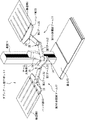
図1は、本実施の形態によるダブルアーム型ロボットの外観を示す概略斜視図である。図1において、本実施の形態によるダブルアーム型ロボット1は、第1の多関節アーム11と、第2の多関節アーム12と、アーム支持部13と、基柱14と、基台15とを備える。
(Embodiment 1)
A double arm type robot according to Embodiment 1 of the present invention will be described with reference to the drawings.
FIG. 1 is a schematic perspective view showing an appearance of a double arm type robot according to the present embodiment. In FIG. 1, a double arm robot 1 according to the present embodiment includes a first articulated
第1の多関節アーム11は、第1アーム21と、第2アーム22と、ハンド部23とを備える。第1アーム21は、関節部24によってアーム支持部13と連結される。以下、関節部24を、基端の関節部24と呼ぶこともある。第2アーム22は、第1アーム21の基端の関節部24と反対側の一端に、関節部25によって回動可能に連結される。第2アーム22の第1アーム21と反対側の一端は、関節部26によってハンド部23と回動可能に連結される。ハンド部23には、搬送物(ワーク)2が載置される。搬送物2は、例えば、ガラス基板や、半導体基板などの薄板状のものであってもよい。ハンド部23は、搬送時に搬送物2がずれたり落ちたりしないように固定することができるチャッキング機構を有してもよく、あるいは、有さなくてもよい。関節部24,25,26の回転軸は、平行であることが好適である。本実施の形態では、関節部24,25,26の回転軸が鉛直方向であるとする。
The first articulated
第2の多関節アーム12も、第1の多関節アーム11と同様なものである。より詳細には、第1アーム31,第2アーム32,ハンド部33がそれぞれ、第1アーム21,第2アーム22,ハンド部23に対応し、関節部34,35,36がそれぞれ、関節部24,25,26に対応する。第1及び第2の多関節アーム11,12のそれぞれの基端の関節部24,34の回転中心軸は、同一直線上に存在する。第1及び第2の多関節アーム11,12において、それぞれ対応するアームやハンド部は、大きさが同じであることが好適であるが、そうでなくてもよい。
The second articulated arm 12 is the same as the first articulated
第1及び第2の多関節アーム11,12のハンド部23,33と反対側の一端は、基端の関節部24,34によってそれぞれ回動可能にアーム支持部13に連結される。また、第1及び第2の多関節アーム11,12は、互いに干渉することなくアーム支持部13に連結されているものとする。すなわち、第1及び第2の多関節アーム11,12のそれぞれが自由に伸縮や回転等の動作を行ったとしても、両者の一部が接触することがないものとする。本実施の形態では、図1で示されるように、アーム支持部13の上面側に第1の多関節アーム11が設けられており、アーム支持部13の下面側に第2の多関節アーム12が設けられている。また、第1の多関節アーム11は、その一部がアーム支持部13の上面よりも下側にならないように、第1アーム21の上側に第2アーム22が連結されており、第2アーム22の上側にハンド部23が連結されている。また、第2の多関節アーム12は、その一部がアーム支持部13の下面よりも上側にならないように、第1アーム31の下側に第2アーム32が連結されており、第2アーム32の下側にハンド部33が連結されている。なお、本実施の形態では、このような構成によって第1及び第2の多関節アーム11,12が干渉しないようにされているが、他の構成によって両者が干渉しないようにされてもよい。例えば、図1と同様の構成において、第1及び第2の多関節アーム11,12の両方がアーム支持部13の上面側、あるいは下面側に設けられていてもよい。ただし、第1の多関節アーム11が第2の多関節アーム12の上側に位置し、第1アーム21と第1アーム31とは、回動しても接触しないものとする。
One ends of the first and second
また、アーム支持部13は、第1アーム21,31が基端の関節部24,34の回転軸を中心として、360度回転することができるようになっていることが好適である。すなわち、アーム支持部13は、第1アーム21,31以上の水平方向の長さを有しており、さらに、第1アーム21が連結されているアーム支持部13の上面側には、第1アーム21の回転の妨げとなる突起等が存在しないことが好適である。同様に、第1アーム31が連結されているアーム支持部13の下面側には、第1アーム31の回転の妨げとなる突起等が存在しないことが好適である。
In addition, the
基柱14は、アーム支持部13の第1及び第2の多関節アーム11,12と反対側の一端を鉛直方向に移動可能に保持している。そのアーム支持部13の上下移動機構については後述する。基柱14は、基台15に固定される。基台15は、例えば、工場やクリーンルームの床に配置される台であってもよく、あるいは、工場やクリーンルームの床そのものであってもよい。なお、上記特許文献1〜3では、基柱が基台に対して旋回可能であったが、本実施の形態によるダブルアーム型ロボット1では、基柱14は基台15に固定されているため、旋回することはできない。なお、基台15が工場等の床に配置される台である場合には、その基台15が工場等の床に対して動く可動構造にしてもよい。その場合であっても、基台15を動かすのは、例えば、ロボットの設置の際や、工場等のレイアウトの変更の際であって、第1及び第2の多関節アーム11,12による運搬物2,3の搬送を行っている際には基台15は動かないものとする。
The
図2は、本実施の形態によるダブルアーム型ロボット1の電気的な制御について説明するための図である。図2において、本実施の形態によるダブルアーム型ロボット1は、第1の制御部101と、第2の制御部102と、上下制御部103と、第1のアーム駆動部111と、第1の関節回動部112と、第2のアーム駆動部121と、第2の関節回動部122と、上下駆動部131とを備える。
FIG. 2 is a diagram for explaining electrical control of the double arm type robot 1 according to the present embodiment. In FIG. 2, the double-arm robot 1 according to the present embodiment includes a
第1のアーム駆動部111は、第1の多関節アーム11を駆動する。すなわち、第1のアーム駆動部111は、第1の多関節アーム11を基端の関節部24において回動させる。この第1のアーム駆動部111による第1の多関節アーム11の回動が行われることにより、例えば、第1の多関節アーム11の全体が基端の関節部24の回転軸を中心として回動することになる。
The first
第1の関節回動部112は、第1の多関節アーム11における基端の関節部24でない2以上の関節部、すなわち、関節部25,26において、第2アーム22及びハンド部23を回動させる。この第1の関節回動部112による第2アーム22及びハンド部23の回動と、前述の第1のアーム駆動部111による第1アーム21の回動とが連携することにより、第1の多関節アーム11は、搬送物2を直線的に搬送することができる。この動作については後述する。
The first joint rotation unit 112 rotates the
本実施の形態では、第1の関節回動部112が、駆動手段113と、回動伝達手段114とを備えているものとする。駆動手段113は、第2アーム22を第1アーム21に対して回動させる。回動伝達手段114は、第1アーム21に対する第2アーム22の回動を伝達することにより、その回動に応じてハンド部23を第2アーム22に対して回動させる。回動伝達手段114として、例えば、ベルトとベルト車を用いてもよく、あるいは、複数のギアを用いてもよい。
In the present embodiment, it is assumed that the first joint rotation unit 112 includes a
第1の制御部101は、第1の多関節アーム11の第1アーム21及び第2アーム22を伸ばしきった伸長状態と、第1の多関節アーム11の第1アーム21及び第2アーム22を折り畳み、ハンド部23を引き込んだ縮み状態との間で第1の多関節アーム11を伸縮させる伸縮動作の際に、第1の多関節アーム11が伸縮動作を行うように第1のアーム駆動部111及び第1の関節回動部112を制御する。本実施の形態では、第1の関節回動部112の制御は、駆動手段113を制御することによって行われる。また、第1の制御部101は、第1の多関節アーム11の伸縮動作の方向を回転させる回転動作の際に、第1のアーム駆動部111が第1の多関節アーム11を回動させるように制御する。これらの制御の詳細については後述する。
The
第2のアーム駆動部121は、第2の多関節アーム12を駆動する。すなわち、第2のアーム駆動部121は、第2の多関節アーム12を基端の関節部34において回動させる。この第2のアーム駆動部121による第2の多関節アーム12の回動が行われることにより、例えば、第2の多関節アーム12の全体が基端の関節部34の回転軸を中心として回動することになる。
The second
第2の関節回動部122は、第2の多関節アーム12における基端の関節部34でない2以上の関節部、すなわち、関節部35,36において、第2アーム32及びハンド部33を回動させる。この第2の関節回動部122による第2アーム32及びハンド部33の回動と、前述の第2のアーム駆動部による第1アーム31の回動とが連携することにより、第2の多関節アーム12は、搬送物3を直線的に搬送することができることは、第1の多関節アーム11の場合と同様である。
The second joint rotation unit 122 rotates the second arm 32 and the hand unit 33 at two or more joint parts that are not the base
本実施の形態では、第2の関節回動部122が、駆動手段123と、回動伝達手段124とを備えているものとする。駆動手段123は、第2アーム32を第1アーム31に対して回動させる。回動伝達手段124は、第1アーム31に対する第2アーム32の回動を伝達することにより、その回動に応じてハンド部33を第2アーム32に対して回動させる。回動伝達手段124として、例えば、ベルトとベルト車を用いてもよく、あるいは、複数のギアを用いてもよいことは、回動伝達手段114の場合と同様である。
In the present embodiment, it is assumed that the second joint rotation unit 122 includes a
第2の制御部102は、第2の多関節アーム12の第1アーム31及び第2アーム32を伸ばしきった伸長状態と、第2の多関節アーム12の第1アーム31及び第2アーム32を折り畳み、ハンド部33を引き込んだ縮み状態との間で第2の多関節アーム12を伸縮させる伸縮動作の際に、第2の多関節アーム12が伸縮動作を行うように第2のアーム駆動部121及び第2の関節回動部122を制御する。本実施の形態では、第2の関節回動部122の制御は、駆動手段123を制御することによって行われる。また、第2の制御部102は、第2の多関節アーム12の伸縮動作の方向を回転させる回転動作の際に、第2のアーム駆動部121が第2の多関節アーム12を回動させるように制御する。これらの制御の詳細については後述する。
The
上下駆動部131は、アーム支持部13を基柱14の長さ方向、すなわち鉛直方向に移動させる。この上下駆動部131によるアーム支持部13の上下の移動が行われることによって、第1及び第2の多関節アーム11,12が鉛直方向に移動されることになる。
The
上下制御部103は、アーム支持部13を鉛直上向き、あるいは、鉛直下向きに移動させる際に、上下駆動部131がアーム支持部13を上向き、あるいは、下向きに移動させるように制御する。
The
なお、例えば、第1のアーム駆動部111、駆動手段113、第2のアーム駆動部121、駆動手段123、上下駆動部131は、サーボモータであり、第1の制御部101、第2の制御部102、上下制御部103は、それらのサーボモータからのフィードバックを用いて、第1のアーム駆動部111等を制御するようにしてもよい。
For example, the first
また、第1のアーム駆動部111と、第2のアーム駆動部121とは、それぞれ独立して第1の多関節アーム11と、第2の多関節アーム12とを回動させることができることが好適である。この場合には、第1の多関節アーム11と、第2の多関節アーム12とは、連動しないで回動することができるようになる。なお、両者が連動して回動するようにしてもよい。
In addition, the first
また、第1の関節回動部112と、第2の関節回動部122とは、それぞれ独立して第1の多関節アーム11の第2アーム22及びハンド部23と、第2の多関節アーム12の第2アーム32及びハンド部33とを回動させることができることが好適である。この場合であって、第1及び第2のアーム駆動部111、121が独立して第1及び第2の多関節アーム11、12を回動させる場合には、第1の多関節アーム11と、第2の多関節アーム12とは、連動しないで伸縮動作を行うことができるようになる。なお、第1及び第2の関節回動部112、122が、連動して第2アーム22及びハンド部23と、第2アーム32及びハンド部33とを回動させるようにしてもよい。
In addition, the first joint turning unit 112 and the second joint turning unit 122 are respectively independent of the
次に、図3〜図5を用いて、第1及び第2のアーム駆動部111,121、並びに、第1及び第2の関節回動部112,122によって、第1及び第2の多関節アーム11,12が駆動される機構についてより詳細に説明する。
Next, with reference to FIGS. 3 to 5, the first and second multi-joints are operated by the first and second
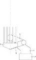
図3は、アーム支持部13と、第1アーム21,31の一部との断面を示す概略図である。図3において、第1のアーム駆動部111であるモータ41の回転がベルト43によって伝達されてベルト車45が回転し、第1関節部24の減速機47を介して第1アーム21が回動される。このように、モータ41が回転することにより、第1アーム21がアーム支持部13に対して回動することになる。
FIG. 3 is a schematic view showing a cross section of the
また、駆動手段113であるモータ42の回転がベルト44によって伝達されてベルト車46が回転し、第1関節部24の回転軸48を介して、ベルト車49が回転される。
Further, the rotation of the
図4において、ベルト車49の回転がベルト50によって伝達されてベルト車61が回転し、そのベルト車61の回転に応じて第2アーム22が第2関節部25の回転支軸62を中心に回動する。一方、回転支軸62は、第1アーム21に固定されており、その回転支軸62にベルト車63が固定されている。したがって、ベルト車61の回転に応じて第2アーム22が第1アーム21に対して回転することによって、ベルト車63は、第2アーム22に対して相対的に回転することになる。
In FIG. 4, the rotation of the
図5において、ベルト車63の相対的な回転がベルト64によって伝達されてベルト車65が回転し、そのベルト車65の回転に応じてハンド部23が第3関節部26の回転軸を中心に回動する。なお、第2アーム22に設けられているベルト車63と、ベルト車65との直径の比は、1:2であるとする。したがって、第2アーム22に対してベルト車63が1単位だけ回転すると、ベルト車65は、1/2単位回転することになる。その結果、図6で示されるように、第2関節部25において第2アーム22が第1アーム21に対して2θだけ回転すると、第3関節部において、ハンド部23は、第2アーム22の回転方向と逆方向にθだけ回転することになる。なお、第1アーム21に対して固定されたベルト車63と、ベルト64と、ハンド部23と連結されたベルト車65とによって、回動伝達手段114が構成されることになる。
In FIG. 5, the relative rotation of the
なお、モータ42の回転によって、第2関節部25で第2アーム22を回動させる際にも、第1関節部24あるいは第2関節部25において減速機を用いて回転速度を減少させ、トルクを向上させるようにしてもよい。
Even when the
また、図3〜図5を用いて、第1の多関節アーム11の構成について説明したが、第2の多関節アーム12も、第1の多関節アーム11と同様の構成を有しており、その説明を省略する。
Moreover, although the structure of the 1st articulated
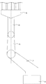
次に、伸縮動作と回転動作とについて説明する。ここでは、第1の多関節アーム11の動作について説明するが、第2の多関節アーム12についても同様である。伸縮動作は、図7で示される伸長状態と、図8で示される縮み状態との間で第1の多関節アーム11を伸縮させる動作のことである。なお、伸縮動作は、図7の伸長状態から図8の縮み状態に至るまでの一部の動作であってもよく、あるいは、図8の縮み状態から図7の伸長状態に至るまでの一部の動作であってもよい。また、伸縮動作の際に、ハンド部23は、180度逆側を向いていてもよい。
Next, the expansion / contraction operation and the rotation operation will be described. Although the operation of the first articulated
ここで、図7の伸長状態から図6の状態にする場合について説明する。この伸縮動作において、モータ41が回転し、第1アーム21をアーム支持部13に対してθだけ時計回りに回動させる。それと同時に、モータ42も回転して、第2アーム22を第1アーム21に対して2θだけ反時計回りに回動させる。すると、前述のように、その第2アーム22の回転に応じてハンド部33がθだけ時計回りに回動し、図6で示されるようになる。したがって、伸縮動作の際には、第1関節部24での第1アーム21の回動角度と、第2関節部25での第2アーム22の回動角度とが1:2の関係となり、逆方向となるように制御することによって、ハンド部23は、回転することなく、図6中の伸縮方向に移動することになる。このように、伸縮動作時には、ハンド部23の櫛の長さ方向は、伸縮方向と同じ方向となる。したがって、伸縮動作時には、第1の制御部101は、第1アーム21の回動角度と、第2アーム22の回動角度とが、1:2の関係となり、逆方向となるように第1のアーム駆動部111(モータ41)、及び駆動手段113(モータ42)を制御するものとする。
Here, a case where the extended state of FIG. 7 is changed to the state of FIG. 6 will be described. In this expansion / contraction operation, the
回転動作の際には、モータ41のみが回転し、第1関節部24において、第1アーム21を回動させる。この回転動作によって、伸縮動作時の伸縮方向が回転することになる。この回転動作時には、第1の制御部101は、伸縮方向を変更したい所望の角度だけ、第1アーム21が回動するように第1のアーム駆動部111(モータ41)を制御するものとする。この回転動作によって、図9で示されるように、ハンド部23の櫛形状の向きを、約270度の範囲において変更することができる。したがって、本実施の形態によるダブルアーム型ロボット1は、第1及び第2の多関節アーム11,12を支える台座を旋回させなくても、基柱14の向き以外の約270度の範囲においては、台座を旋回させた場合と同様の動作を行うことができるようになる。
During the rotation operation, only the
この伸縮動作と、回転動作とを組み合わせることによって、例えば、第1のストッカからガラス基板等の搬送物を取り出し、その搬送物を、第1のストッカの開口部と直行する方向に開口部を有する第2のストッカに収納することができる。その場合には、第1のストッカから搬送物を取り出すための伸縮動作を行い、縮み状態において回転動作を行って伸縮方向を90度回転させ、その後、第2のストッカに搬送物を収納するための伸縮動作を行ってもよい。なお、ダブルアーム型ロボット1は第1及び第2の多関節アーム11,12を備えているため、一方の多関節アームで搬送物をストッカに収納する動作を行い、別の多関節アームで別の搬送物をストッカから取り出す動作を行うようにしてもよい。あるいは、第1及び第2の多関節アーム11,12の両方で、搬送物をストッカに収納する処理、あるいは、搬送物をストッカから取り出す処理を同時に行ってもよい。また、第1及び第2の多関節アーム11,12が同一の伸縮方向で伸縮動作を行う際に、第2関節部25,35が伸縮方向の側方の同じ側に突出するようにしてもよく、あるいは、そうでなくてもよい。
By combining the expansion and contraction operation and the rotation operation, for example, a transported object such as a glass substrate is taken out from the first stocker, and the transported object has an opening in a direction perpendicular to the opening of the first stocker. It can be stored in the second stocker. In that case, an expansion / contraction operation for taking out the conveyed product from the first stocker is performed, a rotation operation is performed in the contracted state to rotate the expansion / contraction direction by 90 degrees, and then the conveyed product is stored in the second stocker. The telescopic operation may be performed. Since the double arm type robot 1 includes the first and second
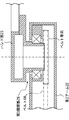
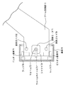
図10は、アーム支持部13の上下移動機構の構成を示す概略図である。図10において、アーム支持部13は、昇降ガイド79,80によって、基柱14と一定の距離を保ったまま、上下に移動可能に構成されている。また、上下駆動部131である昇降モータ71によって、ウォーム72が回転され、そのウォーム72と係合するウォームホイール73が回転されることによって、ウォームホイール73に固定されているシャフト74が回転する。そのシャフト74の回転に応じて、一組のピニオン歯車75,76が回転する。一組のピニオン歯車75,76に係合する一組のラック77,78は、基柱14に固定されているため、アーム支持部13は、ピニオン歯車75,76の回転に応じて上下に移動する。したがって、上下制御部103は、上下駆動部131(昇降モータ71)の回転方向と回転量とを制御することによって、アーム支持部13が任意の量だけ上下に移動するようにできる。
FIG. 10 is a schematic diagram showing the configuration of the vertical movement mechanism of the
以上のように、本実施の形態によるダブルアーム型ロボット1によれば、第1及び第2の多関節アーム11,12を支える基柱14等を旋回させることなく、第1及び第2の多関節アーム11,12を多くの方向で伸縮させることができる。その結果、簡易な構成であり、省スペースであるダブルアーム型ロボット1を実現することができる。また、基柱14が基台15に直接固定されているため、旋回台を介して基台に固定されている場合に比べて安定させることができ、例えば、地震発生時にも、より安定していると考えられる。また、上記特許文献2,3に比べると旋回させる対象となる重量が格段に軽くなるため、疲労の蓄積などもより少なくなると考えられる。また、上記特許文献2,3のような旋回台を旋回させる必要がないため、旋回台を旋回させる機構が不要となり、搬送物2,3を搬送する際の下側の領域を拡大することができうる。また、上記特許文献2,3のロボットに対して、極端に機構が複雑化したり大型化したりすることもない。
As described above, according to the double arm type robot 1 according to the present embodiment, the first and second multi-arms 1 and the second multi-joint robot 1 and the second
また、本実施の形態によるダブルアーム型ロボット1では、第1及び第2の多関節アーム11,12の両方を単一のアーム支持部13で支持する構成としたことにより、上記特許文献2,3のように、アームごとにアーム支持部を設けた場合に比べて、基柱14に掛かる重量を軽くすることができうる。
Further, in the double arm type robot 1 according to the present embodiment, both the first and second
また、第1及び第2の多関節アーム11,12が互いに干渉することがないため、一方の多関節アームを、他方の多関節アームの位置に関係なく自由に動かすことができる。また、第1のアーム駆動部111と第2のアーム駆動部121とが連動せず、第1の関節回動部112と第2の関節回動部122とが連動しないことによって、第1及び第2の多関節アーム11,12を独立して動かすことができる。したがって、第1の多関節アーム11によって、第1のストッカから搬送物を取り出して第2のストッカに収納する処理を行っている際に、第2の多関節アーム12によって、第3のストッカから搬送物を取り出して第4のストッカに収納する処理を行うことも可能であり、処理の自由度が上がることになる。特に、上記特許文献2,3のように基柱が旋回する場合には、一般に伸縮方向が一方向となるため、2個の多関節アームで別方向の伸縮を行うことができないが、本実施の形態によるダブルアーム型ロボット1は、第1及び第2の多関節アーム11,12のそれぞれで別方向の伸縮を行うことができる。
Further, since the first and second articulated
また、第1及び第2の多関節アーム11,12がそれぞれ2個のアームによって構成されることにより、各多関節アームにおいて、必要十分な処理を最低限のアームの構成によって実現することができるようになる。近年、液晶パネル等の搬送物2,3が大型化してきており、それに伴って搬送物2,3が重くなってきている。したがって、多関節アームを構成するアームの数を最小限にすることによって、重たい搬送物2,3を搬送する際の第1及び第2の多関節アーム11,12のたわみを少なくすることができうる。
In addition, since each of the first and second articulated
なお、本実施の形態では、ダブルアーム型ロボット1が基台15を有する場合について説明したが、そうでなくてもよい。基台15は、例えば、ダブルアーム型ロボット1が用いられるクリーンルームの床や工場の床であり、その床に基柱14を固定してもよい。その場合には、ダブルアーム型ロボット1は、基台を有していなくてもよい。
In the present embodiment, the case where the double arm robot 1 has the base 15 has been described, but this need not be the case. The base 15 is, for example, a clean room floor or a factory floor where the double arm robot 1 is used, and the
また、本実施の形態では、第1の関節回動部112が駆動手段113と回動伝達手段114とから構成され、第2の関節回動部122が駆動手段123と回動伝達手段124とから構成される場合について説明したが、そうでなくてもよい。第1の関節回動部112は、例えば、第2アーム22を第1アーム21に対して回動させる第1の駆動手段と、ハンド部23を第2アーム22に対して回動させる第2の駆動手段とを備えてもよい。この第1の多関節アーム11における第1及び第2の駆動手段のそれぞれは、例えば、サーボモータであってもよい。同様に、第2の関節回動部122は、例えば、第2アーム32を第1アーム31に対して回動させる第1の駆動手段と、ハンド部33を第2アーム32に対して回動させる第2の駆動手段とを備えてもよい。この第2の多関節アーム12における第1及び第2の駆動手段のそれぞれは、例えば、サーボモータであってもよい。
Further, in the present embodiment, the first joint rotation unit 112 includes the driving
また、本実施の形態では、第1及び第2の制御部101,102が、第1及び第2の多関節アーム11,12が伸縮動作や回転動作を行うように第1のアーム駆動部111等を制御する場合について説明したが、第1及び第2の制御部101,102は、それ以外の制御を行ってもよい。
Further, in the present embodiment, the first and
また、本実施の形態では、第1及び第2の多関節アーム11,12がそれぞれ2個のアームを備える場合について説明したが、第1及び第2の多関節アーム11,12は、3個以上の連結されたアームを備えてもよい。その場合でも、3個以上の連結されたアームの一端にはハンド部23,33が回動可能に連結され、他端は、アーム支持部13に基端の関節部23,24によって回動可能に連結されることになる。また、3個以上の連結されたアームのそれぞれも、第1アーム21と第2アーム22との第2関節部25での接続のように、回動可能に連結されるものとする。
In the present embodiment, the case where each of the first and second
また、本実施の形態では、第1及び第2の多関節アーム11,12のそれぞれの基端の関節部24,34の回転中心軸が同一直線上に存在する場合について説明したが、そうでなくてもよい。例えば、両者の回転中心軸がずれていてもよい。
In the present embodiment, the case where the rotation center axes of the
また、本実施の形態では、ダブルアーム型ロボット1について説明したが、シングルアーム型ロボットにおいて、伸縮動作と回転動作とを行う多関節アームを用いてもよい。この場合にも、基柱を旋回させる必要がなくなるというメリットがある。
また、本発明は、以上の実施の形態に限定されることなく、種々の変更が可能であり、それらも本発明の範囲内に包含されるものであることは言うまでもない。
In the present embodiment, the double arm type robot 1 has been described. However, in a single arm type robot, an articulated arm that performs an expansion / contraction operation and a rotation operation may be used. Also in this case, there is an advantage that it is not necessary to turn the base pillar.
Further, the present invention is not limited to the above-described embodiment, and various modifications are possible, and it goes without saying that these are also included in the scope of the present invention.
以上より、本発明によるダブルアーム型ロボットは、簡易な構成とすることができ、例えば、半導体基板やガラス基板等の搬送物をストッカから取り出し、別のストッカに入れたりチャンバ等に入れたりするロボットとして有用である。 As described above, the double arm type robot according to the present invention can have a simple configuration. For example, a robot that takes out a transported object such as a semiconductor substrate or a glass substrate from a stocker and places it in another stocker or a chamber or the like. Useful as.
1 ダブルアーム型ロボット
2、3 搬送物
11 第1の多関節アーム
12 第2の多関節アーム
13 アーム支持部
14 基柱
15 基台
21、31 第1アーム
22、32 第2アーム
23、33 ハンド部
24、34 第1関節部
25、35 第2関節部
26、36 第3関節部
41、42、51、52 モータ
43、44、53、54、50、60、64 ベルト
45、46、49、55、56、59、61、63、65 ベルト車
47、57 減速機
48、58 回転軸
62 回転支軸
71 昇降モータ
72 ウォーム
73 ウォームホイール
74 シャフト
75、76 ピニオン歯車
77、78 ラック
79、80 昇降ガイド
101 第1の制御部
102 第2の制御部
103 上下制御部
111 第1のアーム駆動部
112 第1の関節回動部
113、123 駆動手段
114、124 回動伝達手段
121 第2のアーム駆動部
122 第2の関節回動部
131 上下駆動部
DESCRIPTION OF SYMBOLS 1 Double arm type robot 2, 3 Conveyed
Claims (8)
前記第1及び第2の多関節アームの前記ハンド部と反対側の一端が、基端の関節部によってそれぞれ回動可能に連結されるアーム支持部と、
前記アーム支持部の前記第1及び第2の多関節アームと反対側の一端を鉛直方向に移動可能に保持しており、基台に固定される基柱と、
前記第1の多関節アームを前記基端の関節部において回動させる第1のアーム駆動部と、
前記第2の多関節アームを前記基端の関節部において回動させる第2のアーム駆動部と、
前記第1の多関節アームにおける前記基端の関節部でない2以上の関節部において前記アーム及び前記ハンド部を回動させる第1の関節回動部と、
前記第2の多関節アームにおける前記基端の関節部でない2以上の関節部において前記アーム及び前記ハンド部を回動させる第2の関節回動部と、を備えたダブルアーム型ロボット。 It has a hand part on which a conveyed product is placed and two or more arms that are connected to each other so as to be rotatable by a joint part. The hand part can be turned to one end of the two or more arms by a joint part. First and second articulated arms connected to
One end of the first and second multi-joint arms opposite to the hand portion is arm-supported so as to be pivotable by a base joint portion,
One end of the arm support portion opposite to the first and second articulated arms is movably held in the vertical direction, and a base pillar fixed to a base,
A first arm driving section for rotating the first multi-joint arm at the proximal joint section;
A second arm driving part for rotating the second articulated arm at the joint part at the proximal end;
A first joint rotation part that rotates the arm and the hand part at two or more joint parts that are not the joint part of the proximal end in the first multi-joint arm;
A double-arm robot comprising: a second joint rotation unit configured to rotate the arm and the hand unit at two or more joint portions that are not the joint portion at the base end of the second multi-joint arm.
前記第1の関節回動部及び前記第2の関節回動部は、それぞれ独立して前記第1の多関節アームの前記アーム及び前記ハンド部、前記第2の多関節アームの前記アーム及び前記ハンド部を回動させる、請求項1記載のダブルアーム型ロボット。 The first arm driving unit and the second arm driving unit independently rotate the first articulated arm and the second articulated arm, respectively.
The first joint rotation unit and the second joint rotation unit are respectively independently the arm and the hand unit of the first multi-joint arm, the arm of the second multi-joint arm, and the The double arm type robot according to claim 1, wherein the hand portion is rotated.
前記基端の関節部によって前記アーム支持部と連結される第1アームと、
前記第1アームの前記基端の関節部と反対側の一端に関節部によって回動可能に連結される第2アームとを備え、
前記第2アームの前記第1アームと反対側の一端は、前記ハンド部と連結される、請求項1または請求項2記載のダブルアーム型ロボット。 Each of the first and second articulated arms is
A first arm connected to the arm support by the proximal joint;
A second arm that is pivotally connected to one end of the first arm on the opposite side of the proximal end joint portion by a joint portion;
The double arm type robot according to claim 1, wherein one end of the second arm opposite to the first arm is connected to the hand unit.
前記第2の多関節アームの前記第1アーム及び前記第2アームを伸ばしきった伸長状態と、前記第2の多関節アームの前記第1アーム及び前記第2アームを折り畳み、前記ハンド部を引き込んだ縮み状態との間で前記第2の多関節アームを伸縮させる伸縮動作の際に、前記第2の多関節アームが伸縮動作を行うように前記第2のアーム駆動部及び前記第2の関節回動部を制御し、前記第2の多関節アームの伸縮動作の方向を回転させる回転動作の際に、前記第2のアーム駆動部が前記第2の多関節アームを回動させるように制御する第2の制御部と、をさらに備えた、請求項3記載のダブルアーム型ロボット。 The extended state in which the first arm and the second arm of the first articulated arm are fully extended, the first arm and the second arm of the first articulated arm are folded, and the hand portion is retracted. The first arm driving unit and the first joint are so arranged that the first articulated arm performs an extending / contracting operation when the first articulated arm is expanded / contracted between the contracted state and the contracted state. The first arm drive unit is controlled to rotate the first articulated arm during a rotation operation that controls the rotation unit and rotates the direction of the expansion / contraction operation of the first articulated arm. A first control unit,
The extended state in which the first arm and the second arm of the second articulated arm are fully extended, the first arm and the second arm of the second articulated arm are folded, and the hand unit is retracted The second arm drive unit and the second joint are configured so that the second multi-joint arm performs an expansion / contraction operation when the second multi-joint arm expands / contracts between the contracted state and the second contraction state. The second arm drive unit is controlled to rotate the second articulated arm during a rotation operation that controls the rotation unit and rotates the direction of the expansion and contraction operation of the second articulated arm. The double arm type robot according to claim 3, further comprising a second control unit.
前記第2アームを前記第1アームに対して回動させる駆動手段と、
前記第1アームに対する前記第2アームの回動を伝達することにより、当該回動に応じて前記ハンド部を前記第2アームに対して回動させる回動伝達手段と、を備えた、請求項3または請求項4記載のダブルアーム型ロボット。 Each of the first and second joint rotating parts is
Driving means for rotating the second arm with respect to the first arm;
The rotation transmission means which rotates rotation of the 2nd arm to the 1st arm, and rotates the hand part to the 2nd arm according to the rotation. The double arm type robot according to claim 3 or 5.
Priority Applications (1)
| Application Number | Priority Date | Filing Date | Title |
|---|---|---|---|
| JP2008237583A JP5263945B2 (en) | 2008-09-17 | 2008-09-17 | Double arm robot |
Applications Claiming Priority (1)
| Application Number | Priority Date | Filing Date | Title |
|---|---|---|---|
| JP2008237583A JP5263945B2 (en) | 2008-09-17 | 2008-09-17 | Double arm robot |
Publications (2)
| Publication Number | Publication Date |
|---|---|
| JP2010069552A true JP2010069552A (en) | 2010-04-02 |
| JP5263945B2 JP5263945B2 (en) | 2013-08-14 |
Family
ID=42201811
Family Applications (1)
| Application Number | Title | Priority Date | Filing Date |
|---|---|---|---|
| JP2008237583A Expired - Fee Related JP5263945B2 (en) | 2008-09-17 | 2008-09-17 | Double arm robot |
Country Status (1)
| Country | Link |
|---|---|
| JP (1) | JP5263945B2 (en) |
Cited By (7)
| Publication number | Priority date | Publication date | Assignee | Title |
|---|---|---|---|---|
| CN102050330A (en) * | 2010-11-05 | 2011-05-11 | 深圳市华星光电技术有限公司 | Mechanical arm and transport device provided with same |
| JP2012166297A (en) * | 2011-02-14 | 2012-09-06 | Seiko Epson Corp | Robot hand and robot apparatus |
| JP2013157561A (en) * | 2012-01-31 | 2013-08-15 | Yaskawa Electric Corp | Carrier robot |
| WO2015020071A1 (en) * | 2013-08-08 | 2015-02-12 | 日本電産サンキョー株式会社 | Industrial robot |
| JP2017189862A (en) * | 2016-04-15 | 2017-10-19 | 株式会社安川電機 | Work robot and work system |
| KR101928578B1 (en) | 2011-06-17 | 2018-12-12 | 가부시키가이샤 야스카와덴키 | Transport robot |
| WO2022224823A1 (en) * | 2021-04-23 | 2022-10-27 | 川崎重工業株式会社 | Substrate transfer robot and substrate transfer device |
Citations (5)
| Publication number | Priority date | Publication date | Assignee | Title |
|---|---|---|---|---|
| JPH05109866A (en) * | 1991-10-16 | 1993-04-30 | Nec Corp | Wafer transfer robot |
| JPH06126663A (en) * | 1992-10-16 | 1994-05-10 | Toshiba Corp | Double-armed robot |
| JP2001274218A (en) * | 2000-03-23 | 2001-10-05 | Sankyo Seiki Mfg Co Ltd | Double-arm robot |
| JP2006224218A (en) * | 2005-02-16 | 2006-08-31 | Kohnan Electronic Corp | Multi-articulated robot |
| WO2008007517A1 (en) * | 2006-07-11 | 2008-01-17 | Kabushiki Kaisha Yaskawa Denki | Multi-joint robot and wiring method |
-
2008
- 2008-09-17 JP JP2008237583A patent/JP5263945B2/en not_active Expired - Fee Related
Patent Citations (5)
| Publication number | Priority date | Publication date | Assignee | Title |
|---|---|---|---|---|
| JPH05109866A (en) * | 1991-10-16 | 1993-04-30 | Nec Corp | Wafer transfer robot |
| JPH06126663A (en) * | 1992-10-16 | 1994-05-10 | Toshiba Corp | Double-armed robot |
| JP2001274218A (en) * | 2000-03-23 | 2001-10-05 | Sankyo Seiki Mfg Co Ltd | Double-arm robot |
| JP2006224218A (en) * | 2005-02-16 | 2006-08-31 | Kohnan Electronic Corp | Multi-articulated robot |
| WO2008007517A1 (en) * | 2006-07-11 | 2008-01-17 | Kabushiki Kaisha Yaskawa Denki | Multi-joint robot and wiring method |
Cited By (14)
| Publication number | Priority date | Publication date | Assignee | Title |
|---|---|---|---|---|
| CN102050330A (en) * | 2010-11-05 | 2011-05-11 | 深圳市华星光电技术有限公司 | Mechanical arm and transport device provided with same |
| CN102050330B (en) * | 2010-11-05 | 2013-02-06 | 深圳市华星光电技术有限公司 | Mechanical arm and transport device provided with same |
| JP2012166297A (en) * | 2011-02-14 | 2012-09-06 | Seiko Epson Corp | Robot hand and robot apparatus |
| KR101928578B1 (en) | 2011-06-17 | 2018-12-12 | 가부시키가이샤 야스카와덴키 | Transport robot |
| US8992160B2 (en) | 2012-01-31 | 2015-03-31 | Kabushiki Kaisha Yaskawa Denki | Transfer robot |
| JP2013157561A (en) * | 2012-01-31 | 2013-08-15 | Yaskawa Electric Corp | Carrier robot |
| JP2015033737A (en) * | 2013-08-08 | 2015-02-19 | 日本電産サンキョー株式会社 | Industrial robot |
| WO2015020071A1 (en) * | 2013-08-08 | 2015-02-12 | 日本電産サンキョー株式会社 | Industrial robot |
| CN105008096A (en) * | 2013-08-08 | 2015-10-28 | 日本电产三协株式会社 | Industrial robot |
| TWI558522B (en) * | 2013-08-08 | 2016-11-21 | Nidec Sankyo Corp | Industrial robots |
| KR101680993B1 (en) * | 2013-08-08 | 2016-11-29 | 니혼 덴산 산쿄 가부시키가이샤 | Industrial robot |
| US10276416B2 (en) | 2013-08-08 | 2019-04-30 | Nidec Sankyo Corporation | Industrial robot |
| JP2017189862A (en) * | 2016-04-15 | 2017-10-19 | 株式会社安川電機 | Work robot and work system |
| WO2022224823A1 (en) * | 2021-04-23 | 2022-10-27 | 川崎重工業株式会社 | Substrate transfer robot and substrate transfer device |
Also Published As
| Publication number | Publication date |
|---|---|
| JP5263945B2 (en) | 2013-08-14 |
Similar Documents
| Publication | Publication Date | Title |
|---|---|---|
| JP5263945B2 (en) | Double arm robot | |
| JP5990359B2 (en) | Loading / unloading robot | |
| JP5949917B2 (en) | Robot system and method of manufacturing processed product | |
| TWI357375B (en) | ||
| JP4970128B2 (en) | Industrial robot and collective processing device | |
| CN101454125B (en) | Work transfer system | |
| JP2011119556A (en) | Horizontal multi-joint robot and transportation apparatus including the same | |
| JP2008135630A (en) | Substrate conveying device | |
| JP2001274218A (en) | Double-arm robot | |
| JP4595053B2 (en) | Articulated robot | |
| JP4495509B2 (en) | Transfer robot | |
| JPWO2009034795A1 (en) | Substrate transfer robot, vacuum processing equipment | |
| JP4519824B2 (en) | Double arm robot | |
| WO2016189565A1 (en) | Horizontal articulated robot | |
| JP2009269122A (en) | Workpiece conveying robot | |
| JP4911371B2 (en) | Articulated robot and wiring method | |
| JP2013165241A (en) | Transporting apparatus | |
| JP2014159076A (en) | Substrate transport robot | |
| JP2006198768A (en) | Double arm type robot | |
| JP2012024900A (en) | Double armed robot | |
| JP3169460U (en) | Substrate transfer robot | |
| JP2007260862A (en) | Robot | |
| JP2009285795A (en) | Articulated robot | |
| JP5563271B2 (en) | Substrate transfer robot | |
| JPH0912108A (en) | Transferring device |
Legal Events
| Date | Code | Title | Description |
|---|---|---|---|
| A621 | Written request for application examination |
Free format text: JAPANESE INTERMEDIATE CODE: A621 Effective date: 20110408 |
|
| A977 | Report on retrieval |
Free format text: JAPANESE INTERMEDIATE CODE: A971007 Effective date: 20120622 |
|
| A131 | Notification of reasons for refusal |
Free format text: JAPANESE INTERMEDIATE CODE: A131 Effective date: 20120627 |
|
| A521 | Request for written amendment filed |
Free format text: JAPANESE INTERMEDIATE CODE: A523 Effective date: 20120823 |
|
| A131 | Notification of reasons for refusal |
Free format text: JAPANESE INTERMEDIATE CODE: A131 Effective date: 20130208 |
|
| A521 | Request for written amendment filed |
Free format text: JAPANESE INTERMEDIATE CODE: A523 Effective date: 20130312 |
|
| TRDD | Decision of grant or rejection written | ||
| A01 | Written decision to grant a patent or to grant a registration (utility model) |
Free format text: JAPANESE INTERMEDIATE CODE: A01 Effective date: 20130424 |
|
| A61 | First payment of annual fees (during grant procedure) |
Free format text: JAPANESE INTERMEDIATE CODE: A61 Effective date: 20130426 |
|
| R150 | Certificate of patent or registration of utility model |
Free format text: JAPANESE INTERMEDIATE CODE: R150 Ref document number: 5263945 Country of ref document: JP Free format text: JAPANESE INTERMEDIATE CODE: R150 |
|
| R250 | Receipt of annual fees |
Free format text: JAPANESE INTERMEDIATE CODE: R250 |
|
| R250 | Receipt of annual fees |
Free format text: JAPANESE INTERMEDIATE CODE: R250 |
|
| R250 | Receipt of annual fees |
Free format text: JAPANESE INTERMEDIATE CODE: R250 |
|
| R250 | Receipt of annual fees |
Free format text: JAPANESE INTERMEDIATE CODE: R250 |
|
| R250 | Receipt of annual fees |
Free format text: JAPANESE INTERMEDIATE CODE: R250 |
|
| R250 | Receipt of annual fees |
Free format text: JAPANESE INTERMEDIATE CODE: R250 |
|
| LAPS | Cancellation because of no payment of annual fees |