JP2010069543A - Driving machine - Google Patents
Driving machine Download PDFInfo
- Publication number
- JP2010069543A JP2010069543A JP2008236446A JP2008236446A JP2010069543A JP 2010069543 A JP2010069543 A JP 2010069543A JP 2008236446 A JP2008236446 A JP 2008236446A JP 2008236446 A JP2008236446 A JP 2008236446A JP 2010069543 A JP2010069543 A JP 2010069543A
- Authority
- JP
- Japan
- Prior art keywords
- trigger
- arm
- trigger arm
- region
- shaft portion
- Prior art date
- Legal status (The legal status is an assumption and is not a legal conclusion. Google has not performed a legal analysis and makes no representation as to the accuracy of the status listed.)
- Granted
Links
Images


Landscapes
- Portable Nailing Machines And Staplers (AREA)
Abstract
Description
本発明は打込機に関し、特に打ち込み動作の切換機構に関する。 The present invention relates to a driving machine, and more particularly to a driving mechanism switching mechanism.
建築内装の仕上建材を施工するには、仕上建材を接着剤により接着した後に仕上用の釘を仕上建材に設けられた比較的幅の狭い溝内に打ち込んで取り付けるのが一般的である。仕上用の釘は、仕上建材の外観色に合わせて釘の頭部を同色に着色すると共に仕上建材の溝に打込むため小頭径のものが使用され、仕上建材に傷や打痕が残らないように配慮してきれいな仕上りが要求される。 In order to construct a finished building material for a building interior, it is common to attach the finished building material with an adhesive and then drive a finishing nail into a relatively narrow groove provided in the finished building material. For finishing nails, the head of the nail is colored in the same color according to the appearance color of the finished building material, and a small head diameter is used to drive it into the groove of the finished building material, leaving scratches and dents on the finished building material. A clean finish is required with care taken into account.
マガジンに装填された連結釘をビットガイドの先端から一本ずつ打ち出す釘打機においては、釘の誤発射を防止するためにコンタクトアームを設け、コンタクトアームの先端を仕上建材に押し付けコンタクトアームを上方へ後退させることにより始めてトリガ操作を有効とさせ、次にトリガレバーを引き込み操作すれば釘が発射されて仕上建材に打ち込まれるよう構成されている。 In the nailing machine that drives the connecting nails loaded in the magazine one by one from the tip of the bit guide, a contact arm is provided to prevent accidental firing of the nail, the tip of the contact arm is pressed against the finished building material, and the contact arm is The trigger operation is made effective only when the trigger lever is retracted, and then the nail is fired and driven into the finished building material by pulling the trigger lever.
これに対し、出願人は、特許文献1に示されるようにコンタクトアームを常時上死点側に押圧する押圧手段を設けた釘打機を提案している。この釘打機では、コンタクトアーム先端部を仕上建材に強く押し付けなくても良いので仕上り及び作業性が向上している。 On the other hand, the applicant has proposed a nailing machine provided with a pressing means for constantly pressing the contact arm toward the top dead center as shown in Patent Document 1. In this nailing machine, the finish and workability are improved because the tip of the contact arm does not need to be strongly pressed against the finished building material.
また出願人は、特許文献2に示されるように、コンタクトアームの下降途中でトリガアームの自由端部とコンタクトアーム先端部との係合を外し、コンタクトアームを押圧手段により上死点に復帰させ、さらにトリガアームをスライド式にすると共にトリガ内でトリガアームを常時前方に押圧する押圧手段を設け、トリガを開放した時、トリガアームの自由端部とコンタクトアーム上端部が再び係合する釘打機を提案している。この釘打ち機では、コンタクトアームが部材に接触した時の誤発射や部材の傷付けを防止し、また、釘を打込んだ後、釘打機本体を移動させる時、大きく釘打機本体を持ち上げたりする必要がなく、釘打機本体を滑らせるように移動させることを可能とし、打込み効率及び換作性が向上する。
しかし特許文献1及び特許文献2のコンタクトアームを押圧手段により上死点に復帰させるタイプの釘打機では、トリガレバーの引き動作を保持したまま、コンタクトアームを被打込み部材に押し当て、上死点に動かすことによって、連続的に釘を打込む、いわゆる連続打ちができないといった欠点があった。打込み作業においては、正確さや仕上りよりも、迅速で効率的な作業が求められる場合があり、その際、連続打ちで作業を行うことが一般的である。しかし、従来の構造では、引き操作を行ったトリガレバーを初期位置に戻してから、再び一からの釘打込み操作を始めなければならない、いわゆる単発打ち作業しか行えなかった。
However, in the type of nailing machine in which the contact arm of Patent Document 1 and
よって本発明は、上記した従来技術の欠点をなくし、いわゆる連続打ちが出来る状態への切換を可能とした釘打機を提供することを目的とする。 Accordingly, an object of the present invention is to provide a nailing machine that eliminates the above-described drawbacks of the prior art and can be switched to a state in which so-called continuous driving can be performed.
上記課題を解決するために本発明は、ハウジングと、該ハウジングの端部に設けられて止具を射出するノーズ部と、該ハウジング若しくは該ノーズ部に設けられ該止具の射出方向と直交する方向に延びる回動軸部に枢支され、該回動軸部回りに回動するトリガレバーと、起動されて該止具の射出動作を許容する起動部と、該トリガレバーに該回動軸部と平行な軸で枢支され該回動軸部の軸方向と直交する方向に進退すると共に、該トリガレバーの回動動作に応じて該起動部と当接し該起動部を起動させるトリガアームと、該射出方向と平行移動可能に該ノーズ部から該トリガレバー近傍位置まで跨って配置され、該トリガアームに対して係合・非係合の状態を採ると共に、該トリガアームと係合した状態で該起動部を起動可能な位置に該トリガアームを移動させるコンタクトアームと、該コンタクトアームを反射出方向へ付勢する付勢手段と、該トリガアームを該回転軸部側に付勢する付勢部と、該回動軸部及び該回動軸部近傍に設けられ、該付勢部と協働して該トリガアームを該回動軸部に近接した第一進退領域と該回動軸部から離間した第二進退領域とに選択的に進退移動させる切換機構と、を備え、該トリガアームと該コンタクトアームとは、該トリガアームが該第一進退領域に位置する状態において該トリガレバーの回動動作後も該トリガアームと該コンタクトアームとが係合し、該トリガアームが該第二進退領域に位置する状態において該トリガレバーの回動動作後に該トリガアームと該コンタクトアームとの係合が解かれる位置に配置されている打込機を提供する。 In order to solve the above-described problems, the present invention provides a housing, a nose portion that is provided at an end portion of the housing and injects a stopper, and is orthogonal to an injection direction of the stopper that is provided in the housing or the nose portion. A trigger lever that is pivotally supported by a rotation shaft portion extending in a direction and rotates around the rotation shaft portion, an activation portion that is activated to allow an injection operation of the stopper, and the rotation shaft on the trigger lever A trigger arm that is pivotally supported by an axis parallel to the portion and advances and retreats in a direction orthogonal to the axial direction of the rotation shaft portion, and abuts on the activation portion and activates the activation portion according to the rotation operation of the trigger lever And arranged to straddle from the nose part to the vicinity of the trigger lever so as to be movable in parallel with the injection direction, and engaged / disengaged with the trigger arm and engaged with the trigger arm. In the state, the trigger is moved to a position where the trigger can be activated. A contact arm that moves the arm, a biasing means that biases the contact arm in the reflecting direction, a biasing portion that biases the trigger arm toward the rotating shaft, a rotating shaft, and a rotating shaft. Provided in the vicinity of the moving shaft portion, and in cooperation with the urging portion, the trigger arm is selectively used as a first advancing / retreating region near the rotating shaft portion and a second advancing / retreating region separated from the rotating shaft portion. The trigger arm and the contact arm are arranged so that the trigger arm and the contact arm are in contact with each other even after the trigger lever is rotated in a state where the trigger arm is located in the first advance / retreat region. In the state where the arm is engaged and the trigger arm is positioned in the second forward / backward movement area, the strike arm disposed at a position where the trigger arm and the contact arm are disengaged after the trigger lever is rotated. Provide a built-in machine.
この様な構成によると、打込機の使用者が切換機構でトリガアーム位置を第一進退領域と第二進退領域とに切り換えることにより、止具の打ち込み後にトリガアームとコンタクトアームとが係合・非係合の二つの状態を選択することができる。トリガアームとコンタクトアームとが係合している状態ではいわゆる連続打ちが可能であり、トリガアームとコンタクトアームとが非係合の状態ではいわゆる単発打ちのみが可能となるため、切換機構を切り換えることにより、単発打ちと連続打ちとを選択することができる。また切換機構があることにより、切換機構の動作状態を視認することにより、打込機が単発打ちと連続打ちとのいずれの状態にあるかを容易に判断することができる。 According to such a configuration, the trigger arm and the contact arm are engaged after the stopper is driven by switching the trigger arm position between the first advance / retreat area and the second advance / retreat area by the switching mechanism by the driving machine user. • Two disengaged states can be selected. When the trigger arm and contact arm are engaged, so-called continuous hitting is possible, and when the trigger arm and contact arm are not engaged, only so-called single hitting is possible. Thus, single shot and continuous shot can be selected. Further, since there is a switching mechanism, it is possible to easily determine whether the driving machine is in a single shot or a continuous shot by visually checking the operating state of the switching mechanism.
上記構成の打込機において、該起動部は該トリガレバーの回動操作に応じて該トリガアームに押し込まれるプランジャを有し、該プランジャと該トリガアームとには、該トリガアームが該第二進退領域に位置した状態で互いに係合する係合部と被係合部とがそれぞれ設けられていることが好ましい。 In the driving machine having the above-described configuration, the activation unit includes a plunger that is pushed into the trigger arm in response to a turning operation of the trigger lever, and the trigger arm is connected to the second arm and the trigger arm. It is preferable that an engaging portion and an engaged portion that are engaged with each other while being positioned in the advance / retreat region are provided.
この様な構成によると、第二進退領域に位置したトリガアームがプランジャと当接した後は、トリガアームとプランジャとの係合により、トリガアームを第二進退領域に留まらせることができる。 According to such a configuration, after the trigger arm located in the second advance / retreat area comes into contact with the plunger, the trigger arm can remain in the second advance / retreat area by the engagement between the trigger arm and the plunger.
また該切換機構は、回転部と切換アームと押圧部とを備えて構成され、該回転部は該回動軸部と平行な回転軸回りに回転操作されると共に該回転部の周面の一部が切り欠かれた凹部が形成され、該切換アームは該回動軸部を軸として揺動可能に構成され、該凹部内に挿入されると共に該回転部の回転に応じて該凹部内から排出されて該回転部の回転運動を揺動運動に変換する揺動変換部と、概揺動変換部の揺動に応じて該トリガアームに当接し該トリガアームを該第一進退領域から該第二進退領域に向けて移動させる当接部と、を有し、該押圧部は該トリガアームが該押圧部の付勢力に抗って移動するように該切換アームを付勢することが好ましい。 The switching mechanism includes a rotating portion, a switching arm, and a pressing portion, and the rotating portion is rotated about a rotation axis parallel to the rotating shaft portion, and is provided on one of the peripheral surfaces of the rotating portion. A recess is formed by cutting out the portion, and the switching arm is configured to be swingable about the rotating shaft, and is inserted into the recess and from within the recess according to the rotation of the rotating portion. A swing converting portion that is discharged and converts the rotational motion of the rotating portion into a swing motion; and the trigger arm is brought into contact with the trigger arm according to the swing of the general swing converting portion, and the trigger arm is A contact portion that moves toward the second advance / retreat region, and the pressing portion biases the switching arm so that the trigger arm moves against the biasing force of the pressing portion. .
この様な構成によると、切換機構を回転部と切換アームと押圧部との簡単な構成とすることができ、構成部品の増加を抑制することができる。 According to such a structure, a switching mechanism can be made into a simple structure of a rotation part, a switching arm, and a press part, and the increase in a component can be suppressed.
また該トリガレバーと該回転部とは、該トリガレバーの回動軌跡が該回転部の一部と干渉する位置に配置され、該回転部には、該回動軌跡と干渉する位置に該トリガレバーが通過可能な切欠が形成されていることが好ましい。 The trigger lever and the rotating part are arranged at a position where the turning locus of the trigger lever interferes with a part of the rotating part, and the trigger is placed at a position where the turning part interferes with the turning locus. It is preferable that a notch through which the lever can pass is formed.
この様な構成によると、トリガレバーの回動軌跡と回転部とが干渉するため、回転部をトリガレバーの誤動作防止のロックとすることができる。 According to such a configuration, the rotation trajectory of the trigger lever interferes with the rotating portion, so that the rotating portion can be used as a lock for preventing the trigger lever from malfunctioning.
また上記課題を解決するために、ハウジングと、該ハウジングの端部に設けられて止具を射出するノーズ部と、該ハウジング若しくは該ノーズ部に設けられ該止具の射出方向と直交する方向に延びる回動軸部に枢支され、該回動軸部回りに回動するトリガレバーと、第一領域と第二領域との間で移動可能なプランジャを有すると共に該プランジャが押し込まれて該第二領域から該第一領域まで移動して該止具の射出を許容する起動部と、該トリガレバーに該回動軸部と平行な軸部で枢支されて該軸部回りに回動可能に構成され、該トリガレバーの回動動作に応じて該プランジャを押し込むトリガアームと、該射出方向と平行移動可能に該ノーズ部から該トリガレバー近傍位置まで跨って配置され、該トリガアームと係合して該プランジャを押し込める位置に該トリガアームを移動させるコンタクトアームと、該コンタクトアームを反射出方向へ付勢する付勢手段と、を有し、該トリガアームは、自由端が該回動軸部の周面に掛止されると共に該自由端と該軸部との間で該プランジャに当接し、該回転軸部は略円柱状に構成され軸回りに回転可能であると共に該トリガアームが掛止する該周面の一部が切り欠かれた凹部が形成され、該プランジャは、該トリガレバーが回動動作すると共に該自由端が該周面に掛止した状態において該トリガアームにより押し込まれて常に第一領域に位置し、該トリガレバーが回動動作すると共に該自由端が該凹部内に掛止した状態において該トリガアームにより第二領域に位置する打込機を提供する。 In order to solve the above problems, a housing, a nose portion provided at an end portion of the housing to inject a stopper, and a direction provided in the housing or the nose portion and orthogonal to the injection direction of the stopper A trigger lever pivotally supported by the extending pivot shaft and pivoting about the pivot shaft, and a plunger movable between the first region and the second region, and the plunger is pushed into the first lever An activation part that moves from the second area to the first area to allow the stopper to be ejected, and a pivot that is pivotally supported by the trigger lever at a shaft parallel to the pivot shaft. A trigger arm that pushes the plunger in response to the pivoting movement of the trigger lever, and is arranged to straddle from the nose portion to a position near the trigger lever so as to be movable in parallel with the injection direction. And press the plunger. A contact arm that moves the trigger arm to a retractable position, and a biasing means that biases the contact arm in the reflecting direction, and the trigger arm has a free end on the circumferential surface of the rotating shaft portion. The rotating shaft portion is formed in a substantially columnar shape and is rotatable around the axis and the trigger arm is hooked, and is engaged with the plunger between the free end and the shaft portion. A recess is formed in which a part of the surface is cut out, and the plunger is always pushed first by the trigger arm in a state where the trigger lever rotates and the free end is hooked on the peripheral surface. There is provided a driving machine which is located in a region and is located in a second region by the trigger arm in a state where the trigger lever rotates and the free end is hooked in the recess.
この様な構成によると、回動軸部の回転により、トリガレバーが引き動作されて回動動作した状態でのプランジャの位置を第一領域と第二領域とに配置することができる。常に第一領域にあるプランジャは、第二領域から第一領域への移動ができないため、止具の射出が許容されることはない。よってこの状態では、プランジャを第二領域に移動させるためにトリガレバーの引き動作をやめる必要があり、故にいわゆる連続打ちをすることができない。これに対して第二領域にあるプランジャは、第二領域から第一領域へ移動できるため、コンタクトアームを動作させることにより、トリガレバーを引き動作した状態で、続けて止具を射出する連続打ちが可能になる。 According to such a configuration, the position of the plunger in a state where the trigger lever is pulled and rotated by the rotation of the rotation shaft portion can be arranged in the first region and the second region. Since the plunger that is always in the first region cannot move from the second region to the first region, injection of the stopper is not permitted. Therefore, in this state, in order to move the plunger to the second region, it is necessary to stop the pulling operation of the trigger lever, so that so-called continuous hitting cannot be performed. On the other hand, since the plunger in the second region can move from the second region to the first region, the contact arm is operated to pull the stopper continuously while pulling the trigger lever. Is possible.
本発明の打込機によれば、いわゆる連続打ちが出来る状態への切換が可能になる。 According to the driving machine of the present invention, it is possible to switch to a state in which so-called continuous driving can be performed.
以下、本発明の第一の実施の形態に係る打込機について、図1乃至図16に基づき説明する。図1に示される打込機である釘打機1は、止具である釘11(図2)を打ち込む工具であり、その動力として圧縮空気を用いている。 Hereinafter, a driving machine according to a first embodiment of the present invention will be described with reference to FIGS. A nail driver 1 which is a driving machine shown in FIG. 1 is a tool for driving a nail 11 (FIG. 2) which is a stopper, and uses compressed air as its power.
釘打機1は、ハウジング2と、ノーズ部3と、から主に構成され、ハウジング2には、後述の射出方向と交差する方向に延びるハンドル2Aが一体に設けられている。図示しない圧縮機からの圧縮空気を蓄積するために、釘打機1のハンドル2A及びハウジング2内に蓄圧室2aが形成されている。蓄圧室2aは図示しないエアホースを介して図示しない圧縮機に接続される。
The nailing machine 1 is mainly composed of a
ハウジング2内には円筒状のシリンダ21が設けられている。シリンダ21内には上下に摺動可能にピストン4Aが設けられている。ピストン4Aにはドライバブレード4Bが一体に形成されている。このドライバブレード4Bが釘11を打撃するためにピストン4Aと共に移動する方向を射出方向と定義し、ハウジング2に対するノーズ部3側を下側(反対を上側)と定義する。
A
シリンダ21下端外周にはドライバブレード4Bを上死点に復帰させるための圧縮空気を貯める戻り室21aが設けられている。シリンダ21の軸方向中央部には逆止弁21Aが備えられ、逆止弁21Aにはシリンダ21内からシリンダ21外の戻り室21aへの一方向にのみ流通させる空気通路が形成され、またシリンダ21下方には、戻り室21aに常時開放されている図示せぬ空気通路が形成されている。またシリンダ21下端には釘11打ち込み後のピストン4Aの余剰エネルギーを吸収するためのピストンバンパ4Cが設けられている。
A
シリンダ21の上側外周には、メインバルブ41、メインバルブ41を収容するメインバルブ室42、メインバルブ41を下死点側に付勢するメインバルブスプリング43等から構成されている。またメインバルブ41には空気通路44が形成されており、ハウジング2上部に設けた図示せぬ排気穴を経てメインバルブ41がシリンダ21の端部と当接している状態でのみ大気と連通可能に構成されている。メインバルブ41は、シリンダ21の端部に当接してシリンダ21内空間と蓄圧室2aとを遮断しており、後述のトリガバルブ部14から空気通路14aを介してメインバルブ室42に圧縮空気が流入されたときのみ、上方に移動してシリンダ21内空間と蓄圧室2aとを連通させている。シリンダ21内空間と蓄圧室2aとが連通することにより、シリンダ21内におけるピストン4A上方空間の圧力がピストン4A下方空間の圧力より高くなり、この圧力差に基づいてピストン4Aが下方へ急激に移動し、これに応じてドライバブレード4Bが後述の射出通路3a内を下方へ移動する。
The upper outer periphery of the
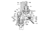
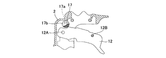
ハンドル2Aの基部には、図2に示されるように、トリガレバー12、トリガアーム13、トリガバルブ部14、及び切換機構が設けられている。
As shown in FIG. 2, a
トリガレバー12は、ハウジング2に設けられて射出方向及びハンドル2Aの延出方向と直交する方向を軸方向とする回動軸部12Aに枢支されており、回動軸部12A回りを回動可能に構成されている。トリガレバー12の自由端部分には、トリガアーム13を枢支する軸部12B及び軸部12Bに枢支されたバネ支持部12Eが設けられている。トリガレバー12の回動軸部12A近傍位置には、トリガレバー12とハウジング2との間に介装されてトリガレバー12に図2の紙面上時計回り(トリガレバー12の自由端が下側に回動)する回転力を付加するバネ12Dが設けられている。またトリガレバー12の回動軸部12A近傍であって、回動軸部12Aに関してトリガレバー12自由端の反対側の位置に後述の切換アーム16と当接可能な当接部12Cが設けられている。
The
トリガアーム13は、基部13Aと、第一腕部13Cと、第二腕部13Dと、突起部13Eとから主に構成されている。基部13Aは長孔が形成され長孔内に軸部12Bが挿入されており、軸部12Bの軸回りに回動可能であるとともに軸部12Bの軸方向と直交する方向に移動可能に構成されている。第一腕部13Cは、基部13Aから回動軸部12Aに向かう方向に向けて延出されている。第二腕部13Dは、第一腕部13Cの途中から枝分かれすると共に第一腕部13Cの下方に位置し、第一腕部13Cと平行に回動軸部12Aに向かう方向へと延出されている。突起部13Eは、第一腕部13Cの第二腕部13Dが分岐する箇所近傍から上方へ向けて突出して設けられている。第一腕部13Cは、その先端が後述の切換アーム16と主に当接する箇所であり、第二腕部13Dは、その下面部分が後述のコンタクトアーム32の後端部32Bと係合・非係合の関係を採る箇所である。
The
基部13Aとバネ支持部12Eとの間には付勢部であるスプリング13Bが介在しており、スプリング13Bはトリガアーム13を回動軸部12Aに向かう方向に付勢している。トリガアーム13は、長孔に軸部12Bが挿入されて枢支されているため、スプリング13Bに付勢されて回動軸部12Aに近接した領域(第一進退領域)に位置し、かつスプリング13Bの付勢力に抗して回動軸部12Aから離間した領域(第二進退領域)に移動可能である。
A
トリガバルブ部14は、ハウジング2のトリガアーム13上方に位置する箇所に設けられており、空気通路14aを介してメインバルブ室42に送気される圧縮空気の制御をしている。またトリガバルブ部14にはプランジャ15が設けられており、プランジャ15が第二領域である下死点若しくは下死点近傍位置から第一領域である上死点若しくは上死点近傍位置まで移動することにより、メインバルブ室42に圧縮空気が送気される。
The
プランジャ15は、バネ14Aにより下方に付勢されると共に、下端部に突起部13Eと係合可能な係合部15Aが設けられ、突起部13Eがトリガアーム13と当接可能な位置に配置されている。
The
切換機構は、切換アーム16と回転部17と押圧部であるバネ18とから主に構成されている。切換アーム16は回動軸部12Aに揺動可能に枢支されており、当接部16Aと揺動変換部16Bとを主に備えている。当接部16Aは回動軸部12Aと直交する方向に延びて構成されており、その先端部分がトリガアーム13の自由端である第一腕部13C端部及び第二腕部13D端部と当接可能に構成されている。
The switching mechanism mainly includes a switching
揺動変換部16Bは、当接部16Aと一体であると共に回動軸部12Aと直交すると共に当接部16Aと交差する方向に延出された腕部より構成されており、回転部17と係合して回転部17の回転運動を回動軸部12A回りの切換アーム16の揺動運動に変換している。揺動変換部16Bと当接部16Aとは一体であるため、当接部16Aも回動軸部12A回りを揺動する。当接部16Aにはトリガアーム13の自由端が当接可能であるため、トリガアーム13の自由端が当接部16Aに当接した状態で当接部16Aがスプリング13Bの付勢方向に抗う方向に揺動することにより、トリガアーム13を第一進退領域から第二進退領域に移動させることができる。また揺動変換部16Bと当接部16Aとは、揺動変換部16Bと当接部16Aとの間であって狭角側となる位置に回転部17を挿入可能な角度で交差している。
The
切換アーム16において、回動軸部12Aの近傍位置には、当接部12Cと当接可能な被当接部16Cが設けられている。当接部12Cが被当接部16Cに当接することにより、切換アーム16の図2紙面上時計回り(当接部16Aがスプリング13Bの付勢方向に抗う方向)への揺動が規制される。また当接部12Cが被当接部16Cに当接した状態でトリガレバー12が引かれることにより、切換アーム16が図2紙面上反時計回り(当接部16Aがスプリング13Bの付勢方向に従う方向)に揺動する。
In the switching
回転部17は円柱状に構成されて円柱の軸方向が回動軸部12Aと平行になるようにハウジング2の回動軸部12A近傍位置に回転可能に支持されており、その一部がトリガレバー12の回動軸部12A回りの回動軌跡と重なっている。また図4に示されるように回転部17は、ハウジング2外に位置して回転操作されるノブ17Aを備えると共に、周面の一部が切り欠かれた凹部17aと、凹部17aの両脇に形成された切欠17b、17bとが形成されている。
The rotating
凹部17aは図2に示されるように、回転部17と直交する断面が略くの字状に成るように穿設されており、凹部17a内に揺動変換部16Bが挿入可能に形成されている。切欠17bは、トリガレバー12の回動軌跡と重なる位置に配置されており、切欠17b内を回動軌跡が通過可能に構成されている。よって回転部17を回転させ、切欠17bがトリガレバー12の回動軌跡上にある状態でのみトリガレバー12は回動可能であり、切欠17bがトリガレバー12の回動軌跡上に無い状態(回転部17の周面がトリガレバー12の回動軌跡上にある状態)ではトリガレバー12は回動不能になる。尚、凹部17aと切欠17bとの位置関係は、図14に示されるように、それぞれの開口部分が周面において反対になるように配置されている。
As shown in FIG. 2, the
バネ18はねじりバネであり切換アーム16とハウジング2との間に介在しており、図2紙面上時計回り(当接部16Aがトリガアーム13を付勢する方向)に揺動するように切換アーム16を付勢している。バネ18の付勢力は当接部16Aがトリガアーム13に当接してトリガアーム13をスプリング13Bの付勢力に抗って第一進退領域から第二進退領域へと移動させる程度である。よって切換機構を回転部17と切換アーム16と押圧部であるバネ18との簡単な構成とすることができ、構成部品の増加を抑制することができる。
The
ノーズ部3はハウジング2の下端に位置してハウジング2に接続されるプレート31と、プレート31の下方に設けられるビットガイド33と、プレート31及びビットガイド33に射出方向と平行な方向に往復摺動可能に支持されているコンタクトアーム32とを含んで構成されている。
The
コンタクトアーム32は、ビットガイド33の下端から下方に延出されると共にトリガレバー12近傍位置まで跨って配置されており、その下端に被打ち込み部材Wと当接する先端部32Aが規定され、トリガレバー12近傍位置にトリガアーム13を担持しトリガアーム13との係合・非係合の関係を採る後端部32Bが規定されている。また図3に示されるようにコンタクトアーム32は付勢手段であるバネ33A,33Aによりプレート31及びビッドガイド33に対し上方向(反射出方向)に移動するように付勢されている。このバネ33A、33Aの付勢力はプランジャ15を付勢しているバネ14Aの付勢力より弱く構成されている。またノーズ部3には、ビットガイド33とプレート31とを貫通し、ドライバブレード4Bが挿通する射出通路3aが形成されている。
The
またノーズ部3においては、射出通路3a内に釘11を供給すると共に釘11が複数本束ねられて連結された束を内蔵しているマガジン装置10がプレート31に接続されている。
In the
マガジン装置10は、図2に示されるように、マガジン10Aとフィーダ10Bとから主に構成されている。マガジン10Aは、ビットガイド33近傍に設けられて、ハンドル2Aの延出方向と略平行に配置されており、内部に釘11の束を内蔵している。フィーダ10Bはマガジン10A内に内蔵され、図示せぬバネを有しており、図示せぬバネの弾性力により釘11を射出通路3a内に向けて付勢している。
As shown in FIG. 2, the
上記構成の釘打機1で釘11をいわゆる単発打ちと連続打ちする動作について説明する。
An operation of continuously driving the
単発打ちをする際には、図2に示されるように、コンタクトアーム32の先端部32Aを被加工部材Wに押しつけるのと前後してノブ17A(図4)を回転させ、図5に示されるように凹部17a内に揺動変換部16Bが挿入される位置(単発位置)に回転部17を配置する。この時に切欠17bは図14に示されるように、トリガレバー12の回動軌跡と重なる位置に配置されるため、トリガレバー12と回転部17とが干渉することはない。
When performing a single shot, as shown in FIG. 2, the
この状態において切換アーム17は、バネ18の付勢力により図5紙面上時計回りに回転して揺動変換部16Bが17a内に挿入され、当接部16Aがトリガアーム13の自由端位置に当接してトリガアーム13を付勢し、第二進退領域へと移動させる。またトリガアーム13は、第二腕部13Dの自由端近傍位置でコンタクトアーム32の後端部32Bの最端部に担持されてコンタクトアーム32と浅く結合しているが、未だプランジャ15とは係合していない。
In this state, the switching
次に使用者がトリガレバー12を引いて回動軸部12A回りにトリガレバー12を回動させる。この状態においては、トリガレバー12の回動に伴い当接部12Cと被当接部16Cとが当接して切換アーム16が図5紙面上反時計回りに傾動する。この時に当接部12Cがトリガアーム13の付勢されている方向に揺動するため、トリガアーム13は、第一進退領域に移動しようとする。しかしプランジャ15とトリガアーム13とが当接し、係合部15Aと突起部13Eとが係合するため、当接部12Cがトリガアーム13から離間しても依然としてトリガアーム13は、第二進退領域に位置している。
Next, the user pulls the
更にトリガレバー12を引き、図7に示されるようにプランジャ15が上死点近傍位置まで移動した状態でトリガバブル部14が作動し、空気通路14aを通してメインバルブ室42に圧縮空気を送気し、ピストン4A及びドライバブレード4Bを作動させ(図1)、釘11を被打ち込み部材Wに打ち込む(図2)。
Further, the
トリガ13を引ききった状態で釘打機1を被打ち込み部材Wから離間させると、コンタクトアーム32を上方に付勢するバネ33Aに対して、プランジャ15を下方に付勢するバネ14Aの方が強いと共にトリガアーム13は軸部12B回りに回動可能であるため、図8に示されるように、コンタクトアーム32はプランジャ15によりトリガアーム13を介して下方に付勢されて下方に移動する。またトリガアーム13は、係合部15Aと突起部13Eとが係合した状態にあるため未だ第二進退領域に位置しており、第二進退領域ではトリガアーム13と後端部32Bとの係合が浅くなっている。よってプランジャ15の付勢力によりコンタクトアーム32がある程度まで下降した時点で、図9に示されるようにコンタクトアーム32とトリガアーム13との係合が解かれ、コンタクトアーム32はバネ33Aの付勢力により、再び上方へと移動する。
When the nail driver 1 is moved away from the driven member W with the
コンタクトアーム32とトリガアーム13との係合とが解かれることにより、プランジャ15が下死点近傍位置まで移動する。トリガ13が引かれた状態である共にコンタクトアーム32とトリガアーム13との係合とが解かれた状態では、プランジャ15を押し込んでプランジャ15を上死点近傍位置まで移動させることができないため、図10に示されるようにトリガレバー12を引くのをやめて打ち込み前の位置まで戻す。この状態において、トリガアーム13は、係合部15Aと突起部13Eとの係合が解かれてコンタクトアーム32の後端部32B側面位置にあるが、スプリング13Bの付勢力により、後端部32B側面上を滑り、図5に示される初期位置に戻り、再び後端部32Bの最端部で第二腕部13Dが担持される形態を採る。
When the
上述の様に、回転部17を単発位置にすることにより、トリガ13を引いて釘11を打ち込んだ後は、一端トリガ13を元に戻さない限り再び釘11を打ち込むことはできず、いわゆる単発打ちのみ可能になる。
As described above, by setting the rotating
次に連続打ちについて説明する。連続打ちをする際には、図11に示されるように、ノブ17A(図4)を回転させ、凹部17a内から揺動変換部16Bが排出されて揺動変換部16Bと当接部16Aとの間の位置(連続位置)に回転部17を配置する。この時に切欠17bは図15に示されるように、トリガレバー12の回動軌跡と重なる位置に配置されるため、トリガレバー12と回転部17とが干渉することはない。
Next, continuous strike will be described. When continuously hitting, as shown in FIG. 11, the
この状態において当接部16Aはトリガアーム13と当接しないため、スプリング13Bの付勢力によりトリガアーム13は第一進退領域に移動し、第二腕部13Dの第一腕部13Cから枝分かれした箇所近傍位置でコンタクトアーム32の後端部32Bの最端部に担持され、コンタクトアーム32と深く結合する。
Since the
この状態でトリガレバー12を引くと、図12に示されるようにトリガアーム13とプランジャ15が当接し、プランジャ15がトリガアーム13により押し込まれて上死点近傍位置に移動し、釘11が打ち込まれる。
When the
釘11が打ち込まれた後に釘打機1を被打ち込み部材Wから離すと、図13に示されるようにバネ14Aの付勢力によりプランジャ15及びトリガアーム13を介してコンタクトアーム32が下方に移動するが、トリガアーム13とコンタクトアーム32とは深く係合しているため、単発打ちのようにトリガアーム13とコンタクトアーム32との係合状態が解かれることはない。よって図13の状態から釘打機1の先端部32Aを再び被打ち込み部材Wに押しつけることにより、図12に示されるように後端部32Bが上方に移動して、プランジャ15を上死点近傍位置に移動させ、再び釘11の打ち込みが可能になる。
When the nail driver 1 is moved away from the driven member W after the
上述の様に、回転部17を連続位置にすることにより、トリガ13を引いて釘11を打ち込んだ後、一端トリガ13を元に戻さずとも再び釘11を打ち込むことができる、いわゆる連続発打ちが可能になる。
As described above, by setting the rotating
また釘打ち動作を禁止する際には、回転部17を回転させ、図16に示されるように回転部17の周面がトリガレバー12の回動軌跡と重なるように配置(固定位置)する。これによりトリガレバー12は回動できないため、釘打ち動作は抑制される。よって回転部17を単発位置と連続位置と固定位置との所定の位置に回転させることにより、単発打ちと連続打ち、及び釘11の打ち込みができない状態とすることを容易に選択することができる。また予めハウジングに、回転部17の回転角度に応じた所定の位置を図示しておくことにより、釘打機1の動作状態を容易に視認することができる。
When the nailing operation is prohibited, the rotating
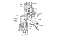
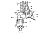
次に本発明の第二の実施の形態にかかる打込機について図17乃至図20に基づき説明する。第二の実施の形態にかかる打込機は、トリガ、トリガアーム、および回転軸部に係る構成以外は、第一の実施の形態と同様であるため、第一の実施の形態に対する変更箇所のみ説明する。 Next, a driving machine according to a second embodiment of the present invention will be described with reference to FIGS. The driving machine according to the second embodiment is the same as that of the first embodiment except for the configuration relating to the trigger, the trigger arm, and the rotating shaft portion, and therefore only the changes to the first embodiment. explain.
第二の実施の形態にかかる釘打機は、図17に示されるように、ハウジング2のトリガバルブ部14近傍位置に、上下方向及び図示せぬハンドルの延出方向と直交する方向を軸方向とする回転軸部112Aが設けられており、回転軸部112Aには、トリガ112が回転軸部112Aの軸回りに回動可能に設けられている。回転軸部112Aはハウジング2外に図示せぬレバーを備えており、この図示せぬレバーを操作することにより軸回りに回転可能に構成されている。また回転軸部112Aの周面の一部には、回転軸部112Aと直交する断面が略くの字状に穿設された凹部112aが形成されており、凹部112a内に後述のトリガアーム113の自由端が挿入可能に形成されている。
As shown in FIG. 17, the nail driver according to the second embodiment has an axial direction in the vertical direction and a direction orthogonal to the extending direction of the handle (not shown) in the vicinity of the
トリガ112の自由端近傍位置には、回転軸部112Aと平行な軸部112Bが設けられており、軸部112Bにはトリガアーム113が軸部112Bの軸回りに回動可能に設けられている。トリガアーム113は、軸部112Bと直交する断面において自由端部分が折り曲げられてクランク状に構成されており、このクランク状の自由端部分が回転軸部112Aの周面及び凹部112a内に係合可能に構成されている。またトリガアーム113において、自由端と基端との略中央部分においてプランジャ15の下端部と当接可能であり、自由端位置においてクランク状部分よりは基端側の位置でコンタクトアーム32の後端部32Bに担持されている。
A
上記構成の釘打機で釘の単発打ちをする際には、図17〜図19に示されるように、図示せぬレバーによって凹部112aの開口が下方に位置するように回転軸部112Aを回転させる。この状態で被打ち込み部材にコンタクトアーム32を当接させトリガ112を引くと、図17及び図18に示されるように、プランジャ15が第二領域である下死点若しくは下死点近傍位置から第一領域である上死点若しくは上死点近傍位置に移動するため、第一の実施の形態で説明したように、釘が打ち込まれる。
When a nail is driven once with the nailing machine having the above-described configuration, as shown in FIGS. 17 to 19, the
トリガ112を引いたまま釘打機を持ち上げると、図19に示されるようにプランジャ15を付勢しているバネ14Aの付勢力によりプランジャ15及びトリガアーム113が下方に移動し、トリガアーム113の下方への移動に応じトリガアーム113を担持しているコンタクトアーム32も下方に移動する。トリガアーム113は、自由端部分が回転軸部112Aの周面に掛止されるため、それ以上下方に移動することができず、この状態においてプランジャ15は未だ上死点近傍の第一領域に位置している。
When the nailing machine is lifted with the
プランジャ15が第二領域から第一領域へと移動することにより釘打ち動作は行われるが、図19に示される状態で釘打機を再び被打ち込み部材に押しつけてコンタクトアーム32を上方に移動させると共にトリガアーム113を上方に移動させたとしても、プランジャ15は第一領域において更に押し込まれるにすぎず、第二領域から第一領域へ移動するという動作を採ることはない。よって連続打ちをすることはできず、一端トリガ112を離して、再度トリガ112を引く単発打ちのみ可能になる。
The nailing operation is performed by moving the
次に連続打ちをする際には、図20に示されるように、凹部112aの開口が上方に位置するように図示せぬレバーによって回転軸部112Aを回転させる。この状態においてトリガアーム113は、自由端位置におけるクランク状部分の最先端部が凹部112a内に位置することが可能になるので、トリガアーム113は単発打ちの状態に比べて下方に位置することが可能になる。
Next, when continuously hitting, as shown in FIG. 20, the
よってトリガ112を引いて釘を打ち込んだ後にトリガ112を引いた状態を維持しつつ釘打機を被打ち込み部材から離間させた際に、バネ14Aの付勢力によりプランジャ15及びトリガアーム113は下方に移動するが、トリガアーム113は、自由端位置が凹部112a内に侵入するため、プランジャ15は、第二領域である下死点近傍位置まで移動することができる。この状態で釘打機を再び被打ち込み部材に押しつけてコンタクトアーム32を上方に移動させると共にトリガアーム113を上方に移動させると、プランジャ15は第二領域から第一領域へ移動するため、再び釘打ち動作をすることができ、いわゆる連続打ちが可能になる。
Therefore, when the nail driver is moved away from the driven member while the
本発明は上述した実施の形態に限定されず、特許請求の範囲で記載された範囲で種々の改良や変形が可能である。例えば、第一、第二の実施の形態のいずれにおいても空気式の釘打機で説明を行ったが、これに限らず電動式や燃焼式の釘打機においてもプランジャをスイッチ等に置き換えるのみで同様に本発明を適用することができる。また釘打機に限らず、被打ち込み部材に当接するコンタクトアームと引き動作されるトリガ及びトリガアームとを備えた構成であるならば、釘打機に限定されず、広く打込機に適用可能であることはいうまでもない。 The present invention is not limited to the above-described embodiments, and various improvements and modifications can be made within the scope described in the claims. For example, in both the first and second embodiments, the pneumatic nailer has been described. However, the plunger is replaced only with a switch or the like not only in this but also in an electric or combustion nailer. Similarly, the present invention can be applied. Further, not only a nail driver, but also a configuration including a contact arm that abuts against a driven member and a trigger and trigger arm that is pulled, the invention is not limited to a nail driver and can be widely applied to a driver. Needless to say.
1・・釘打機 2・・ハウジング 2A・・ハンドル 2a・・蓄圧室 3・・ノーズ部
3a・・射出通路 4A・・ピストン 4B・・ドライバブレード
4C・・ピストンバンパ 10・・マガジン装置 10A・・マガジン
10B・・フィーダ 11・・釘 12・・トリガレバー 12A・・回動軸部
12B・・軸部 12C・・当接部 12D・・バネ 12E・・バネ支持部
13・・トリガアーム 13A・・基部 13B・・スプリング 13C・・第一腕部
13D・・第二腕部 13E・・突起部 14・・トリガバルブ部 14A・・バネ
14a・・空気通路 15・・プランジャ 15A・・係合部 16・・切換アーム
16A・・当接部 16B・・揺動変換部 16C・・被当接部 17・・回転部
17A・・ノブ 17a・・凹部 17b・・切欠 18・・バネ 21・・シリンダ
21A・・逆止弁 21a・・戻り室 31・・プレート 32・・コンタクトアーム
32A・・先端部 32B・・後端部 33・・ビットガイド 33A・・バネ
41・・メインバルブ 42・・メインバルブ室 43・・メインバルブスプリング
44・・空気通路
DESCRIPTION OF SYMBOLS 1 ....
Claims (5)
該ハウジングの端部に設けられて止具を射出するノーズ部と、
該ハウジング若しくは該ノーズ部に設けられ該止具の射出方向と直交する方向に延びる回動軸部に枢支され、該回動軸部回りに回動するトリガレバーと、
起動されて該止具の射出動作を許容する起動部と、
該トリガレバーに該回動軸部と平行な軸で枢支され該回動軸部の軸方向と直交する方向に進退すると共に、該トリガレバーの回動動作に応じて該起動部と当接し該起動部を起動させるトリガアームと、
該射出方向と平行移動可能に該ノーズ部から該トリガレバー近傍位置まで跨って配置され、該トリガアームに対して係合・非係合の状態を採ると共に、該トリガアームと係合した状態で該起動部を起動可能な位置に該トリガアームを移動させるコンタクトアームと、
該コンタクトアームを反射出方向へ付勢する付勢手段と、
該トリガアームを該回動軸部側に付勢する付勢部と、
該回動軸部及び該回動軸部近傍に設けられ、該付勢部と協働して該トリガアームを該回動軸部に近接した第一進退領域と該回動軸部から離間した第二進退領域とに選択的に進退移動させる切換機構と、を備え、
該トリガアームと該コンタクトアームとは、該トリガアームが該第一進退領域に位置する状態において該トリガレバーの回動動作後も該トリガアームと該コンタクトアームとが係合し、該トリガアームが該第二進退領域に位置する状態において該トリガレバーの回動動作後に該トリガアームと該コンタクトアームとの係合が解かれる位置に配置されていることを特徴とする打込機。 A housing;
A nose portion provided at an end of the housing for injecting a stopper;
A trigger lever pivotally supported by a pivot shaft provided in the housing or the nose portion and extending in a direction perpendicular to the injection direction of the stopper, and pivoting around the pivot shaft;
An activation part that is activated to allow an injection operation of the stopper;
The trigger lever is pivotally supported by an axis parallel to the rotation shaft portion, and advances and retreats in a direction perpendicular to the axial direction of the rotation shaft portion, and abuts on the activation portion according to the rotation operation of the trigger lever. A trigger arm that activates the activation unit;
In a state of being able to move parallel to the injection direction and extending from the nose portion to the vicinity of the trigger lever, and being engaged / disengaged with the trigger arm, A contact arm that moves the trigger arm to a position where the activation unit can be activated;
A biasing means for biasing the contact arm in the reflection direction;
An urging portion for urging the trigger arm toward the rotating shaft portion;
The trigger shaft is provided in the vicinity of the rotation shaft portion and in the vicinity of the rotation shaft portion, and the trigger arm is separated from the rotation shaft portion in close proximity to the rotation shaft portion in cooperation with the biasing portion. A switching mechanism that selectively moves forward and backward to the second forward / backward region,
The trigger arm and the contact arm are engaged with the trigger arm and the contact arm even after the trigger lever is rotated in a state where the trigger arm is located in the first advance / retreat region. A driving machine characterized by being disposed at a position where the trigger arm and the contact arm are disengaged after the trigger lever is rotated in the state of being located in the second advance / retreat region.
該プランジャと該トリガアームとには、該トリガアームが該第二進退領域に位置した状態で互いに係合する係合部と被係合部とがそれぞれ設けられていることを特徴とする請求項1に記載の打込機。 The activation unit has a plunger that is pushed into the trigger arm in response to a rotation operation of the trigger lever,
The plunger and the trigger arm are provided with an engaging portion and an engaged portion, respectively, which are engaged with each other when the trigger arm is positioned in the second advance / retreat region. The driving machine according to 1.
該回転部は該回動軸部と平行な回転軸回りに回転操作されると共に該回転部の周面の一部が切り欠かれた凹部が形成され、
該切換アームは該回動軸部を軸として揺動可能に構成され、該凹部内に挿入されると共に該回転部の回転に応じて該凹部内から排出されて該回転部の回転運動を揺動運動に変換する揺動変換部と、概揺動変換部の揺動に応じて該トリガアームに当接し該トリガアームを該第一進退領域から該第二進退領域に向けて移動させる当接部と、を有し、
該押圧部は該トリガアームが該押圧部の付勢力に抗って移動するように該切換アームを付勢することを特徴とする請求項1または請求項2のいずれか一に記載の打込機。 The switching mechanism includes a rotating part, a switching arm, and a pressing part,
The rotating portion is rotated around a rotating shaft parallel to the rotating shaft portion, and a concave portion in which a part of the peripheral surface of the rotating portion is cut out is formed,
The switching arm is configured to be swingable about the rotating shaft portion, and is inserted into the concave portion and is discharged from the concave portion according to the rotation of the rotating portion to swing the rotational motion of the rotating portion. A swing conversion portion that converts to a dynamic motion, and a contact that contacts the trigger arm in accordance with the swing of the general swing conversion portion and moves the trigger arm from the first advance / retreat region toward the second advance / retreat region. And
3. The driving device according to claim 1, wherein the pressing portion biases the switching arm so that the trigger arm moves against a biasing force of the pressing portion. Machine.
該回転部には、該回動軌跡と干渉する位置に該トリガレバーが通過可能な切欠が形成されていることを特徴とする請求項3に記載の打込機。 The trigger lever and the rotating part are arranged at a position where a turning locus of the trigger lever interferes with a part of the rotating part,
4. The driving machine according to claim 3, wherein the rotating portion is formed with a notch through which the trigger lever can pass at a position that interferes with the rotation locus.
該ハウジングの端部に設けられて止具を射出するノーズ部と、
該ハウジング若しくは該ノーズ部に設けられ該止具の射出方向と直交する方向に延びる回動軸部に枢支され、該回動軸部回りに回動するトリガレバーと、
第一領域と第二領域との間で移動可能なプランジャを有すると共に該プランジャが押し込まれて該第二領域から該第一領域まで移動して該止具の射出を許容する起動部と、
該トリガレバーに該回動軸部と平行な軸部で枢支されて該軸部回りに回動可能に構成され、該トリガレバーの回動動作に応じて該プランジャを押し込むトリガアームと、
該射出方向と平行移動可能に該ノーズ部から該トリガレバー近傍位置まで跨って配置され、該トリガアームと係合して該プランジャを押し込める位置に該トリガアームを移動させるコンタクトアームと、
該コンタクトアームを反射出方向へ付勢する付勢手段と、を有し、
該トリガアームは、自由端が該回動軸部の周面に掛止されると共に該自由端と該軸部との間で該プランジャに当接し、
該回転軸部は略円柱状に構成され軸回りに回転可能であると共に該トリガアームが掛止する該周面の一部が切り欠かれた凹部が形成され、
該プランジャは、該トリガレバーが回動動作すると共に該自由端が該周面に掛止した状態において該トリガアームにより押し込まれて常に第一領域に位置し、該トリガレバーが回動動作すると共に該自由端が該凹部内に掛止した状態において該トリガアームにより第二領域に位置することを特徴とする打込機。 A housing;
A nose portion provided at an end of the housing for injecting a stopper;
A trigger lever pivotally supported by a pivot shaft provided in the housing or the nose portion and extending in a direction perpendicular to the injection direction of the stopper, and pivoting around the pivot shaft;
An actuating portion having a plunger movable between the first region and the second region, the plunger being pushed in and moved from the second region to the first region, and allowing the stopper to be ejected;
A trigger arm that is pivotally supported by the trigger lever at a shaft portion parallel to the rotation shaft portion and is rotatable about the shaft portion; and a trigger arm that pushes the plunger in response to the rotation operation of the trigger lever;
A contact arm that is arranged to extend from the nose portion to a position near the trigger lever so as to be movable in parallel with the injection direction, and to move the trigger arm to a position where the plunger can be pushed in by engaging with the trigger arm;
Biasing means for biasing the contact arm in the reflection direction,
The trigger arm has a free end hooked on a peripheral surface of the rotating shaft portion and abuts against the plunger between the free end and the shaft portion,
The rotating shaft portion is formed in a substantially cylindrical shape and is rotatable around an axis, and is formed with a recess in which a part of the peripheral surface on which the trigger arm is hooked is cut out,
The plunger is always positioned in the first region by being pushed by the trigger arm in a state where the trigger lever rotates and the free end is hooked on the peripheral surface, and the trigger lever rotates. A driving machine characterized in that the free end is positioned in the second region by the trigger arm in a state of being hooked in the recess.
Priority Applications (1)
| Application Number | Priority Date | Filing Date | Title |
|---|---|---|---|
| JP2008236446A JP5142084B2 (en) | 2008-09-16 | 2008-09-16 | Driving machine |
Applications Claiming Priority (1)
| Application Number | Priority Date | Filing Date | Title |
|---|---|---|---|
| JP2008236446A JP5142084B2 (en) | 2008-09-16 | 2008-09-16 | Driving machine |
Publications (3)
| Publication Number | Publication Date |
|---|---|
| JP2010069543A true JP2010069543A (en) | 2010-04-02 |
| JP2010069543A5 JP2010069543A5 (en) | 2011-04-14 |
| JP5142084B2 JP5142084B2 (en) | 2013-02-13 |
Family
ID=42201803
Family Applications (1)
| Application Number | Title | Priority Date | Filing Date |
|---|---|---|---|
| JP2008236446A Active JP5142084B2 (en) | 2008-09-16 | 2008-09-16 | Driving machine |
Country Status (1)
| Country | Link |
|---|---|
| JP (1) | JP5142084B2 (en) |
-
2008
- 2008-09-16 JP JP2008236446A patent/JP5142084B2/en active Active
Also Published As
| Publication number | Publication date |
|---|---|
| JP5142084B2 (en) | 2013-02-13 |
Similar Documents
| Publication | Publication Date | Title |
|---|---|---|
| JP6819045B2 (en) | Driving machine | |
| US7677426B2 (en) | Fastener driving device | |
| WO2016002540A1 (en) | Driving machine | |
| JP2001328078A5 (en) | ||
| WO2006126491A1 (en) | Driving tool | |
| JP5585417B2 (en) | Driving machine | |
| JP4752751B2 (en) | Driving machine | |
| WO2013161909A1 (en) | Driving tool | |
| JP2019063924A (en) | Driving tool | |
| JP5348456B2 (en) | Driving machine | |
| JP5076946B2 (en) | Nailer | |
| JP2008068329A (en) | Fastener driver | |
| JP4075462B2 (en) | Contact lever of trigger lever for starting nailer | |
| JP5055817B2 (en) | Contact mechanism in driving tools | |
| JP5142084B2 (en) | Driving machine | |
| JP5286939B2 (en) | Driving machine | |
| JP2008213109A (en) | Driver | |
| JP2014046424A (en) | Driving machine | |
| JP5585418B2 (en) | Driving machine | |
| JP3268136B2 (en) | Operation switching device for air nailing machine | |
| JP2006326733A (en) | Contact mechanism for driving tool | |
| JP4461638B2 (en) | Immersion prevention mechanism in tucker | |
| JP2007075957A (en) | Single driving holding mechanism of nailing machine | |
| JP5310121B2 (en) | Driving machine | |
| JP2019025577A (en) | Driving tool |
Legal Events
| Date | Code | Title | Description |
|---|---|---|---|
| A521 | Written amendment |
Free format text: JAPANESE INTERMEDIATE CODE: A523 Effective date: 20110225 |
|
| A621 | Written request for application examination |
Free format text: JAPANESE INTERMEDIATE CODE: A621 Effective date: 20110225 |
|
| TRDD | Decision of grant or rejection written | ||
| A01 | Written decision to grant a patent or to grant a registration (utility model) |
Free format text: JAPANESE INTERMEDIATE CODE: A01 Effective date: 20121029 |
|
| A01 | Written decision to grant a patent or to grant a registration (utility model) |
Free format text: JAPANESE INTERMEDIATE CODE: A01 |
|
| FPAY | Renewal fee payment (event date is renewal date of database) |
Free format text: PAYMENT UNTIL: 20151130 Year of fee payment: 3 |
|
| R150 | Certificate of patent or registration of utility model |
Ref document number: 5142084 Country of ref document: JP Free format text: JAPANESE INTERMEDIATE CODE: R150 Free format text: JAPANESE INTERMEDIATE CODE: R150 |
|
| A61 | First payment of annual fees (during grant procedure) |
Free format text: JAPANESE INTERMEDIATE CODE: A61 Effective date: 20121111 |
|
| S533 | Written request for registration of change of name |
Free format text: JAPANESE INTERMEDIATE CODE: R313533 |
|
| R350 | Written notification of registration of transfer |
Free format text: JAPANESE INTERMEDIATE CODE: R350 |